OPERATING INSTRUCTIONS 7 SERIES STATIC GENERATORS
|
|
|
- Hannah Sharp
- 5 years ago
- Views:
Transcription


1 OPERATING INSTRUCTIONS 7 SERIES STATIC GENERATORS
2
3 GB Contents Page 1 Introduction 4 2 Safety 5 3 Use 6 4 Checking on Delivered Equipment 6 5 General Specification and Dimensions 7 6 Positioning 10 7 Operating and Control 11 8 Electrical Connection 16 9 Maintenance Health and Safety Certification and EU Declaration of Conformity Troubleshooting Spare Parts and Accessories 26 7 Series Static Generators Iss.1 3
4 1. Introduction This manual applies to the Models 7333, 7360, 7560, and Static Generators. It is essential that you read and understand the complete manual before installing and using this equipment. This is important for safety and for warranty cover. 1.1 Explanation of Symbols Warning! This symbol appearing in the operating instructions refers to operations which, if carried out improperly, may result in serious personal injuries. Caution! This symbol appearing in the operating instructions refers to operations which, if carried out improperly, may result in damage to property. 4
5 2. Safety These Static Generators are intended for use in industrial applications to generate high voltages for static charging applications. A blanking plug is provided fitted to one of the HV output sockets. Remove this plug if both HV sockets are needed. If only one HV output is required, ensure the blanking plug is always fitted to the HV socket not in use. Work on this equipment must be carried out by a competent and qualified electrical engineer. The equipment should be disconnected from the electricity supply before starting any maintenance or installation work. Do not touch any live parts - you will receive an electric shock. The Generator must be earthed for safety and correct performance. Any changes to the equipment without written consent of the manufacturer will nullify the warranty and CE approval. 7 Series Static Generators Iss.1 5
6 3. Use The 7 Series power Fraser static charging heads which are used in industrial applications for temporary adhesion. The system consists of the Static Generator and one or more charging or pinning heads. The Static Generator is a high voltage switching power supply. It is available in either positive polarity or negative polarity. The 7 Series Generators are for indoor use in industrial applications. Static Generators: Installation should be made by a qualified electrical engineer. 4. Checking on Delivered Equipment The equipment leaves our factory in suitable protective packaging. Please check that it is undamaged when it arrives. If there is visible damage contact the Factory or one of our Distributors immediately, before carrying out any installation. Check that the parts that which have been delivered are the same as you have ordered. Loose Parts: Earth Lead. RM and CI Cable as per order. 6
7 5. General Specification and Dimension Construction: 1.5mm steel with mounting brackets. Size: See sketches on pages 8 to 9. Electrical: See page 16 Load: Two HV output connections. External connector boxes can be used to increase the number of HV outputs. Installation: Dry, oil-free location required with ambient temperature of 40 or less. The enclosure is sealed, but the atmosphere should not be polluted, wet or condensing for high voltage applications. 7 Series Static Generators Iss.1 7
8 5. General Specification and Dimension Model Input Power HV Max Output Current Output Power Local Operation Remote Operation Remote Monitoring HV & I Limiting HV Connections 7333 DC 24V DC 30kV 1mA 30W No Yes Yes Yes AC V 30kV 1mA 30W No Yes Yes Yes 2 50/60Hz 7360 DC 24V DC 30kV 2mA 60W Yes Yes Yes Yes AC V 30kV 2mA 60W Yes Yes Yes Yes 2 50/60Hz 7560 DC 24V DC 50kV 1.2mA 60W Yes Yes Yes Yes AC V 50kV 1.2mA 60W Yes Yes Yes Yes 2 50/60Hz DC* 24V DC 30kV 5mA 150W Yes Yes Yes Yes AC* V 30kV 5mA 150W Yes Yes Yes Yes 2 50/60Hz DC* 24V DC 50kV 3mA 150W Yes Yes Yes Yes AC* V 50/60Hz 50kV 3mA 150W Yes Yes Yes Yes 2 Connector Boxes are available where more than 2 electrodes need to be served. * Launch Summer
9 5. General Specification and Dimensions GB 7360/7560/73150 & /73150 & Series Static Generators Iss.1 9
10 6. Positioning The 7 Series Generators should be installed in a clean and dry position. Maximum humidity 70%, non-condensing. Higher levels of humidity affect the process and can cause tracking in the equipment. It may be mounted horizontally or vertically. Operating Temperature: 0 to 40 C. It should be mounted in a vibration-free position. 10
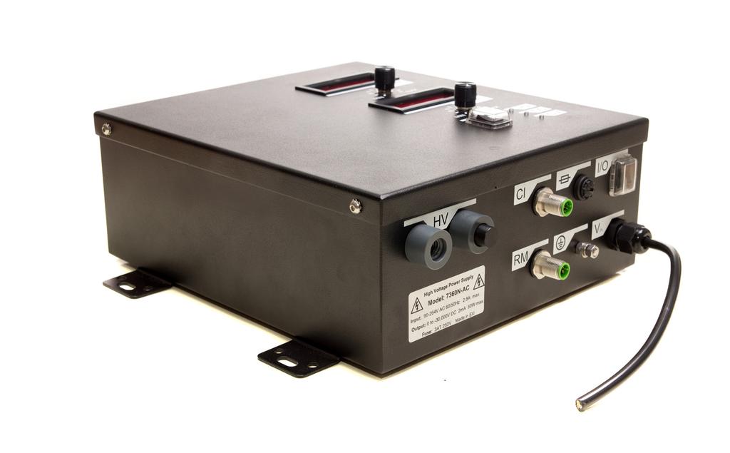
11 7. Operation & Control GB See pages for typical connection examples The 7333 Static Generator has been designed for full integration with a machine or production process. Control Interface M12 8 Pin Power In M12 4 Pin or 115/230V AC ON OFF Ground Remote M12 Monitor 5 Pin M12 5 Pin Fuse Generator Case Controls and Connections ON-OFF switch on front panel. 4 Pin M12 chassis plug : 24VDC: 20VDC to 28VDC. 8 Pin M12 chassis plug: Control Interface. 5 Pin M12 chassis plug: Isolated Remote Monitoring. Two HV output sockets. Ground connection point. 7 Series Static Generators Iss.1 11
12 7. Operation & Control 7360/7560/73150/75150 The operation is based on the familiar conventions on standard low voltage power supplies used in laboratories, test houses and general industry. Limits can be set to the current and voltage levels before the High Voltage (HV) is turned ON. If limits are not required, then turn both voltage and current potentiometers to maximum before switching HV ON. Top Panel Voltage Display HV Potentiometer Current Display Current Potentiometer HV Switch On/Off LED Indicators HV Outputs Front Panel Control Interface CI 8 Pin Fuse On/Off ON OFF Remote RM Monitor 5 Pin RM 5 Pin Ground Poer Fixed 215V/230V Cable AC or M12 x 4 Pin DC 12
13 7. Operation & Control GB Generator Face Power: ON-OFF switch on front panel. DC version: Fixed cable gland and 5m 2 core cable 24V DC: (20-28V DC). HV ON/OFF: The switch on the generator top panel selects High Voltage ON or OFF. High Voltage Potentiometer: HV output voltage set by potentiometer on Generator top panel or through external 0-10V analog signal. A 10V reference is supplied by Generator. Current Potentiometer: HV output current set by potentiometer on Generator top panel or through external 0-10V analog signal. A 10V reference is supplied by Generator. LED Indicators: HV CC CV will illuminate when Generator HV output is ON. will illuminate when Generator is in constant current mode. will illuminate when Generator is in constant voltage mode. Current Display: Voltage Display: Current limit can be set when HV is OFF. Dots appear on current display to show set current limits when voltage is OFF. When voltage is ON these dots disappear and the display shows actual measured current. Output voltage may be set when the HV is OFF. When HV is ON the actual output voltage is displayed. Dots on the voltage display will begin flashing when it goes into constant current mode to show that the set current limit is controlling the voltage. HV Outputs: A blanking plug is provided fitted to one of the HV output sockets. Remove this plug if both HV sockets are needed. If only one HV output is required, ensure the blanking plug is always fitted to the HV socket not in use. Dirt can penetrate into the H.V Output sockets and cause internal tracking if the blanking plugs are not used. 7 Series Static Generators Iss.1 13
14 7. Operation & Control Control Interface (CI) All Models A control interface allows for complete remote control and output monitoring of the Generator. A 10V reference supply is provided for complete remote control and ease of use. Connection: 8 Pin M12 Connector. ON-OFF: Remote ON/OFF switching of HV. Output Indicator: HV ON indicator, sinks 15mA, suitable for remote LED or small relay coils. Voltage Set: 0-10V analog input to set the voltage output demand and it overrides the potentiometer on the top of the Generator case. Current Set: 0-10V analog input to set the current output demand and it overrides the potentiometer on the top of the Generator case. Voltage Sense: Output voltage sense/readout, 0-10V = 0-100%. 1kΩ Output impedance. Current Sense: Output current sense/readout, 0-10V = 0-100%. 1kΩ Output impedance. 10Vdc reference: Supplied from the Generator for remote programming, display and control. Important: Remote voltage/current setting overrides local voltage/current settings. If remote is disconnected, the settings of the local switch and potentiometers on the Generator top panel will determine the output of the Generator. 14
15 7. Operation & Control GB Remote Monitor (RM) All Models A remote monitoring system checks the High Voltage output status of the Generator. Voltage free relay contacts are provided to switch an alarm or feedback to a PLC. Connection: 5 Pin M12 Connector. 63V 4A DC maximum rating. Remote Monitor Relay Operation. HIGH VOLTAGE OFF: PIN 4 connected to PIN 3 Generator NOT producing High Voltage. Generator Power Switch OFF or High Voltage Switch OFF. Otherwise: output arcing, malfunction, or problem with electrical supply. HIGH VOLTAGE ON: PIN 4 connected to PIN 1 Generator producing High Voltage. 7 Series Static Generators Iss.1 15
16 8. Electrical Connections Control Interface - CI: Pin 1 White HV On/Off control. OFF: Pin 1 = <0.7V. ON: Pin 1 = 10-28V DC. Pin 2 Brown Voltage program, 0-10V = 0-100%, Approx. 100kΩ input impedance. Pin 3 Green Current limit/program, 0-10V = 0-100%. Approx. 100kΩ input impedance. Pin 4 Yellow Voltage sense/readout, 0-10V = 0-100%. 1kΩ Output impedance. Pin 5 Grey Current sense/readout, 0-10V = 0-100%, 1kΩ Output impedance. Pin 6 Pink HV output indicator, sinks 15mA DC. Can operate LED indicator by connecting between pins 7 (anode) and 6 (cathode). This wire can also be used to activate small external relay coils. Check this with the Manufacturer. Pin 7 Blue +10Vdc reference output. Can supply up to 100mA DC. Used as reference rail for potentiometers for programming output voltage and/or current and can supply external digital panel meters. Can also be connected to Pin 1 to switch HV. Pin 8 Red / Cable Shield Potentiometers for programming output voltage and/or current and can supply external digital panel meters. Can also be connected to Pin 1 to switch HV. 16
17 8. Electrical Connections GB Remote Monitor Interface - RM: Pin 1 Brown Pin 2 White Pin 3 Blue Pin 4 Black Pin 5 Green/Yellow Normally open relay contact. Not used. No connection. Normally closed relay contact. Relay common pole. Not used. No connection. Ground / Earth: HV Output: M5 threaded connector. This must be connected to an earth / ground. Arc fault protected. Ripple at full load: < 0.5% at full load. Voltage rise time: internally limited to 1kV/ms. Voltage fall time: Depends on load. 7 Series Static Generators Iss.1 17

18 8. Electrical Connections CI Interface Example of Uses The following examples can be used independently or together as required. HV ON/OFF control: Generator Front Panel HV ON/OFF Switch C.I. Remote HV On/Off Input HV OFF Not used / Open / 0V OFF OFF 10-28V DC ON ON Not used / Open ON ON 10-28V DC ON Note: For full remote control of HV, the top panel HV switch must be turned off. Example use of a footswitch or external switch to remote control HV: 18


19 8. Electrical Connections GB Using a remote 10k Ohm, minimum 100mW, potentiometer to control output voltage setting. 0-10V = 0-100%: Using a remote 10k Ohm, minimum 100mW, potentiometer to control output current limit setting, 0-10V = 0-100%: 7 Series Static Generators Iss.1 19
20 8. Electrical Connections Using an external 0-10V FSD ( Full Scale Deflection ) moving coil Voltmeter to monitor actual HV output voltage. 0-10V = 0-100% output: Using an external 0-10V FSD ( Full Scale Deflection ) moving coil Voltmeter to monitor actual HV output voltage. 0-10V = 0-100% output: 20


21 8. Electrical Connections GB Using an external 0-10V FSD ( Full Scale Deflection ) moving coil Voltmeter to monitor actual HV output current. 0-10V = 0-100% output: Digital meters can also be used. The +10V reference voltage output can be used to power digital meters to a maximum current draw of 100mA. Using a remote external LED indicator to show HV output status: Using an opto-isolator device in place of the LED will allow larger external indicators or loads to be activated by the HV output status indicator. 7 Series Static Generators Iss.1 21
22 9. Maintenance IMPORTANT: turn power off before starting any maintenance. There is a leakage resistor to drain the charge in the system when it is turned off. This takes 5 seconds after switching off. The Electrode should not be touched during this period as there will be risk of a small shock. Please note: Fraser Generators have no user serviceable parts. The warranty will be void if the customer attempts to make repairs. 22
23 10. Health and Safety GB It is very important that the user understands the nature of this equipment. Very high voltages and currents are available at the output socket that are more than adequate to kill a healthy adult. High voltages may persist for several minutes after the unit is isolated. Only suitably qualified and trained personnel should service this equipment. Important: Use only Fraser Static Generator Electrodes - these are current limited with a resistance between the high voltage and emitters for safety. The ON OFF switch on the Generator Case must be switched OFF before disconnection of the Bars or undertaking any maintenance. Wait at least 5 seconds after switching OFF to disconnect the Bars. Never disconnect Bars when the high voltage is ON. When working close to high voltage DC equipment the human body can become charged. This can result in a shock when a metal object or part of the machine is touched. 11. Certification and CE Declaration of Conformity We declare that this equipment conforms to the following EC Directives: Low Voltage Directive: 2006/95/EC. EMC Directive: 2004/108/EC. For queries, please contact your Distributor or the Manufacturer. 7 Series Static Generators Iss.1 23
24 12. Troubleshooting Fault No output, LED s off and nothing on the output voltage and current display. Isolate generator from electrical supply. Check fuse fitted to generator. Check electrical supply is within specification. Check supply cable to generator is not damaged. Fault HV output voltage is not reaching set value. If dots are flashing on the voltage display and the CC LED is illuminated, then the load has exceeded the maximum set output current of the generator. Increase the output current setting. Check the load is not arcing to ground and any HV cables are in good condition. Fault HV output keeps resetting. CC LED is on and dots are flashing in the displays. Turn generator off. Disconnect any connections to the HV output of the generator. Turn the HV voltage and current set potentiometer to maximum. Turn the generator on and turn on the HV. If the fault has cleared, then the problem is with the load or HV cables connected to the generator. Check the load is not arcing to ground and check the HV cables are not damaged. Fault Remote On/Off control or HV output setting not working as expected. Turn generator off. Check the remote grounding is bonded to the same potential as the generator ground. 24
25 12. Troubleshooting GB Fault Sparking - Electrode too close to an earthed surface. Increase distance. Cover emitters so that they do not see metal parts. Check that energy is not tracking through dirt - clean the electrode. Fault No Energy. Check HV Supply from Generator. Fault Performance not satisfactory. Check optimal distance between electrode and product - adjust as necessary. Dirty electrode - clean. Check conductivity of material - if paper it must be >1010 Ohm per Square. Check using a Model 730 SRM. Material already charged - Neutralise it with a Static Eliminator. 7 Series Static Generators Iss.1 25
26 13. Spare Parts and Accessories Description Part Number Control Interface M12 x 8 Pin Cable - 5m Control Interface M12 x 8 Pin Cable - 10m Remote Monitor M12 x 5 Pin Cable - 5m Remote Monitor M12 x 5 Pin Cable - 10m M12 x 4 Pin 24V Power Cable - 5m M12 x 4 Pin 24V Power Cable - 5m Extra M of Mains Cable for AC Version
27
28 For more information about static and to view the full range of our products, please visit Scotts Business Park, Bampton, Devon, GB, EX16 9DN T + 44 (0) F + 44 (0) E sales@fraser-antistatic.co.uk W 7 Series Static Generators_OI_Iss1
Operating instructions. Switching amplifier DN0210 DN / / 2015
 Operating instructions Switching amplifier DN0210 DN0220 UK 80011079 / 00 01 / 2015 Contents 1 Preliminary note...4 1.1 Symbols used...4 1.2 Warning signs used...4 2 Safety instructions...5 2.1 General...5
OPERATING INSTRUCTIONS
 OPERATING INSTRUCTIONS 4103 COMPACT 24V DC IONIZING STATIC BAR GB Static Clean static control equipment has been designed to give you many years of productive service. However, the science of static control
Operating instructions. Speed monitor D / / 2014
 Operating instructions Speed monitor D200 80005257 / 00 05 / 2014 Contents 1 Preliminary note...4 1.1 Symbols used...4 1.2 Warning signs used...4 2 Safety instructions...5 2.1 General...5 2.2 Target group...5
Operating instructions Evaluation system for flow sensors VS / / 2013
 Operating instructions Evaluation system for flow sensors VS3000 7097 / 0 07 / 203 Contents Preliminary note...2 2 Safety instructions...3 3 Function and features... Mounting.... Mounting of the sensors...
ADC7520 SERIES. 1600W Battery Chargers and Power Supplies
 ADC7520 SERIES 1600W Battery Chargers and Power Supplies Wide output adjustment range 0 72VDC Analog control by external 0-5VDC voltage Temp.comp charging, sense as on option Power fail relay alarm Master-Slave
D6030S - D6030D INSTRUCTION MANUAL. D SIL 3 Switch/Proximity Detector Repeater Relay Output. Models D6030S, D6030D
 D600S - D600D INSTRUCTI MANUAL SIL Switch/Proximity Detector Repeater Relay, DIN Rail, Models D600S, D600D D600 - SIL Switch/Proximity Detector Repeater Relay G.M. International ISM0- Characteristics General
Operating instructions AS-i SmartLine module AC3200 AC /00 06/2016
 Operating instructions AS-i SmartLine module AC3200 AC3201 80237876/00 06/2016 Contents 1 Preliminary note...3 1.1 Symbols used...3 1.2 Warnings used...3 2 Safety instructions...3 2.1 General...3 2.2 Target
HCS-3600 / 3602 / 3604 Laboratory Grade & High RFI Immunity Switching Mode Power Supply with Rotary Encoder Control
 HCS-3600 / 3602 / 3604 Laboratory Grade & High RFI Immunity Switching Mode Power Supply with Rotary Encoder Control 1. INTRODUCTION User Manual This family of efficient, upgraded SMPS with small form factor,
NTP-5521/5531/5561 SWITCHING MODE POWER SUPPLY
 NTP-5521/5531/5561 SWITCHING MODE POWER SUPPLY USER MANUAL Keep this manual in a safe place for quick reference at all times. This manual contains important safety and operation instructions for correct
Operating instructions. Standstill monitor A / / 2011
 Operating instructions Standstill monitor A300 UK 1 2 3 4 5 6 7 8 7390337 / 01 02 / 2011 1 2 3 4 5 6 7 8 switchpoint min max pulse/min power Made in Germany ifm electronic gmbh D 45127 Essen func. I II
INSTRUCTION MANUAL. Universal AC Input Switching Power Supply 24 Vdc Output DIN-Rail Models PSD1000, PSD1000F PSD PSD1000F
 PSD1000 - PSD1000F INSTRUCTION MANUAL Universal AC Input Switching Power Supply 24 Vdc Output DIN-Rail Models PSD1000, PSD1000F PSD1000 - Universal AC Input Switching Power Supply 24 Vdc Output ISM0089-4
INSTRUCTION MANUAL. SIL 3 Switch/Proximity Detector Repeater Relay Output, Termination Board Models D6032S, D6032D
 D603S D603D INSTRUCTI MANUAL SIL 3 Switch/Proximity Detector Repeater Relay, Termination Board Models D603S, D603D D603 SIL 3 Switch/Proximity Detector Repeater Relay G.M. International ISM0400 General
Switched Mode Power Supply Operating manual PAP800
 Features: Switched mode power supply Wide output 0 144Vdc Analog control by an external 0 5Vdc Power failure alarm output Master-slave connection Powerfinn PAP series is a high power, lightweight, advanced
LED PANEL. User Manual Please read the instructions carefully before use LED-7TC. Innovation, Quality, Performance 15-
 LED PANEL LED-7TC Innovation, Quality, Performance User Manual Please read the instructions carefully before use 15- 9. Fixture Cleaning TABLE OF CONTENTS 1. Safety Instructions 2. Technical Specifications
Installation, Operation and Maintenance Manual
 Document 481200 VGD-100 Vari-Green Drive Installation, Operation and Maintenance Manual Please read and save these instructions for future reference. Read carefully before attempting to assemble, install,
INSTRUCTION MANUAL. SIL 3 Relay Output Module DIN-Rail Models D1092S-069, D1092D-069 D1092S D1092D-069
 D09S09 D09D09 INSTRUCTION MANUAL SIL Relay Output Module DINRail Models D09S09, D09D09 D0909 SIL Relay Output Module ISM00 SIL Applications For Safety Related System and SIL, SIL Applications according
LED W RGBA User Manual
 LED- 245-1W RGBA User Manual Please read the instructions carefully before use CONTENTS 1. Safety Instructions...2 2. Technical Specifications...3 3. How To Set The Unit...4 3.1 Control Panel...4 3.2 Main
H Series PLC. ! : Indicates Compulsion. EH-150 Analog input module EH-AXH8M Instruction manual. Safety precautions DANGER CAUTION COMPULSION
 H Series PLC EH-150 Analog input module EH-AXH8M Instruction manual Thank you for purchasing a Hitachi Programmable Logic Controller. To operate it safely, please read this instruction manual and all the
Zener Barriers Bulletin 937Z
 Technical Data Zener Barriers Bulletin 937Z Topic Page Introduction 2 Mounting 2 Housing 3 Operating Principle 3 Specifications 6 Introduction Allen-Bradley Zener barriers are a cost-effective solution
Signal processor MS96 for flow sensors MS96-11EX0-R/230VAC
 MS96-11EX0-R/230VAC ATEX category II (1) G, Ex Zone 0 ATEX category II (1) D, Ex Zone 20 single-channel signal processor MS96 for connection of an intrinsically safe flow control sensor in zone 0 adjustment
Manual Simatek Control Unit GFC 32
 Manual Simatek Control Unit GFC 32 Original instructions 1400004_GB Ver. 2014.01.09 Index 1. Main features 3 2. Technical features 3 3. Installation guidelines 4 4. Preliminary checks 5 5. Electrical connections
LCI Load Cell Junction Box with Fault Monitor
 LCI Load Cell Junction Box with Fault Monitor User Manual www.mantracourt.co.uk The LCI Load Cell Failure Alarm Manual Chapter 1 Introduction to the LCI...2 Chapter 2 Installing the LCI...3 Figure 2.1
Manual Control Unit GFC 32
 Manual Control Unit 1400004_EN/05.2017 Index 1. Main features 3 2. Technical features 3 3. Installation guidelines 4 4. Preliminary checks 5 5. Electrical connections 5 6. Settings 6 7. Remote control
Part No. Z , IA Nov OPERATION MANUAL. High Voltage Digitalmeter A
 Part No. Z1-109-920, IA001723 Nov. 2005 OPERATION MANUAL High Voltage Digitalmeter 149-30A Use of Operation Manual Please read through and understand this Operation Manual before operating the product.
SoundwebTM. Installation Guide
 105 SoundwebTM Soundweb TM 9000 Installation Guide Soundweb TM Regulatory Information An example of this equipment has been tested and found to comply with the following European and international Standards
D1093S INSTRUCTION MANUAL. D SIL 3 Relay Output Module with Line and Load diagnostics. DIN-Rail Model D1093S
 D109S INSTRUCTION MANUAL SIL Relay Output Module with Line and diagnostics DINRail Model D109S D109 SIL Relay Output Module with Line and diagnostics ISM0096 SIL Applications For Safety Related System
PROCESS AUTOMATION. MANUAL Z-System. Zener Barriers ISO9001
 PROCESS AUTOMATION MANUAL Z-System Zener Barriers ISO9001 With regard to the supply of products, the current issue of the following document is applicable: The General Terms of Delivery for Products and
LED PANEL. User Manual Please read the instructions carefully before use LED-212RGB TABLE OF CONTENTS. 1. Safety Instructions
 TABLE OF CONTENTS LED PANEL 1. Safety Instructions 2. Technical Specifications 3. Installation 4. How to set the unit 5. How to control the fixture 6. DMX512 Configuration 7. DMX512 Connections 8. Troubleshooting
Part No. Z , IA Jul OPERATION MANUAL. High Voltage Digitalmeter A
 Part No. Z1-109-820, IA001705 Jul. 2016 OPERATION MANUAL High Voltage Digitalmeter 149-10A Use of Operation Manual Please read through and understand this Operation Manual before operating the product.
LCI User Manual mantracourt.com
 LCI User Manual mantracourt.com LCI Load Cell Junction Box with Fault Monitor Contents Chapter 1 Introduction to the LCI... 2 Chapter 2 Installing the LCI... 3 Chapter 3 Setting up the LCI... 4 Sequence
BS 287 DUAL CHANNEL POWER SUPPLY. User Manual. January 2017 V1.0
 BS 287 DUAL CHANNEL POWER SUPPLY User Manual January 2017 V1.0 Table of contents 1.0 SAFETY INSTRUCTIONS... 3 2.0 GENERAL DESCRIPTION PS 289... 4 3.0 MECHANICAL INSTALLATION... 5 4.0 MAINS POWER & SAFETY
BS 181 SINGLE CHANNEL POWER SUPPLY USER MANUAL
 BS 181 SINGLE CHANNEL POWER SUPPLY USER MANUAL August 2016 This product is designed and manufactured by: ASL Intercom B.V. Zonnebaan 42 3542 EG Utrecht The Netherlands Phone: +31 (0)30 2411901 Fax: +31
EPS Power Supply
 EPS - 600 Power Supply Installation and Operation Manual Version 1.0 *This instrument is intended for laboratory use only Index A. Important Notice ----------------------------------------------------------------
Operating Instructions
 PRIMETEST 100 PRIMETEST 100 Bracken Hill South West Industrial Estate Peterlee Co Durham SR8 2SW ENGLAND Tel: +44(0)191 5863511 www.seaward.co.uk sales@seaward.co.uk service@seaward.co.uk Part Number
BS 181 SINGLE CHANNEL POWER SUPPLY USER MANUAL
 BS 181 SINGLE CHANNEL POWER SUPPLY USER MANUAL Issue 2011 ASL Intercom BV DESIGNED & MANUFACTURED BY: ASL Intercom B.V. Zonnebaan 42 3542 EG Utrecht The Netherlands Tel: +31 (0)30 2411901 Fax: +31 (0)30
PRO1 V21.xxx series MID DIN rail single phase two wire energy meter
 PRO1 V21.xxx series MID DIN rail single phase two wire energy meter PRO1D V21.212 Version 1.1 Note: the picture on the frontpage is a meter from the series of this meter, it might not be exactly the same
USER MANUAL VIBRATION CONTROL RMA-POWER-BOX 107/230
 USER MANUAL VIBRATION CONTROL Version 2.2 1 IMPORTANT NOTES Electrical danger within the meaning of this documentation or the warning labels on the product itself respectively means that death, serious
MODEL 805 USER MANUAL
 MODEL 805 USER MANUAL All Rights Reserved Page 1 of 12 UNPACKING & INSPECTION Save all packing materials they are required for returns and warranty service. Inspect the 805 and packing materials for any
Laboratory Switch Mode Power Supply Series. Instruction Manual
 Laboratory Switch Mode Power Supply Series Instruction Manual Model 72-8340 1.0 ~ 60VDC 0 ~ 1.6A 72-8345 1.0 ~ 36VDC 0 ~ 3A 72-8350 1.0 ~ 20VDC 0 ~ 5A Copyright 2008, all rights reserved Tenma Test Equipment
OPERATING MANUAL FOR THE 30KV A.C. TEST SET P123. Bicotest High Voltage Products Ltd
 OPERATING MANUAL FOR THE 30KV A.C. TEST SET P123 Product: High Voltage AC Test Set Type: P123 Bicotest High Voltage Products Ltd Hellesdon Park Road, Drayton High Road, Norwich NR6 5DR United Kingdom Phone
Part No. Z , IA Mar OPERATION MANUAL. High Voltage Digitalmeter A
 Part No. Z1-109-820, IA001704 Mar. 2011 OPERATION MANUAL High Voltage Digitalmeter 149-10A Use of Operation Manual Please read through and understand this Operation Manual before operating the product.
SIM-9106/9303 High Current Switching Mode Power Supply with C.C., C.V., Remote Control & Sensing User Manual
 SIM-9106/9303 High Current Switching Mode Power Supply with C.C., C.V., Remote Control & Sensing User Manual 1. INTRODUCTION This family of high power remote sensing, remote control, switching mode CC\CV
Digital I/O Module. Impro (DIO) Digital I/O Module INSTALLATION MANUAL
 Digital I/O Module INSTALLATION MANUAL") COMPONENT CODES: HMI700-1-0-NN-XX HMI701-1-0-NN-XX Digital I/O Module Impro (DIO) Digital I/O Module Specifications INSTALLATION MANUAL The DIO is a Cluster Expansion Module that works in conjunction with
COMPONENT CODES: HMI700-1-0-NN-XX HMI701-1-0-NN-XX Digital I/O Module Impro (DIO) Digital I/O Module Specifications INSTALLATION MANUAL The DIO is a Cluster Expansion Module that works in conjunction with
D5090S INSTRUCTION MANUAL. D A SIL 3 Relay Output Module for NE Load. DIN-Rail and Termination Board, Model D5090S
 D5090S INSTRUCTI MANUAL 4 A Relay Output Module for NE, DIN-Rail and Termination Board, Model D5090S D5090-4 A Relay Output Module for NE G.M. International ISM09-3 Characteristics General Description:
Slim Relay G2RV. Model Number Structure. Ordering Information. Model Number Legend. List of Models. Relay and Socket Combinations
 Slim Relay G2RV The World's First Industrial Slim Relay Large plug-in terminals for reliable connection. LED indicator and mechanical flag to check operation. Transparent housing enables checking relay
SRQ24A. Technical data. Safety notes. Rotary actuator for ball valves Torque 16Nm Nominal voltage AC/DC 24V Control: Open-close Running time 9s
 SRQ24A Rotary actuator for ball valves orque 16Nm Nominal voltage AC/DC 24V Control: Open-close Running time 9s echnical data Electrical data Nominal voltage AC 24V, 50/60Hz / DC 24V Nominal voltage range
PRO-1250D CT MID DIN rail three phase four wire energy meter.
 PRO-1250D CT MID DIN rail three phase four wire energy meter. 1.1 Safety instructions 1.2 Foreword 1.3 MID certificate 1.4 Performance criteria 1.5 Specifications 1.6 Basic errors 1.7 Description 1.8 Dimensions
Professional Entertainment Technology. imove 50SR. Innovation, Quality, Performance 21-
 Innovation, Quality, Performance 21- imove 50SR User Guide Professional Entertainment Technology EC Declaration of Conformity We declare that our products (lighting equipments) comply with the following
Replacement and Calibration of Electronic Spare (PCB) Cassettes - Rosemount 2120 Vibrating Fork Liquid Level Switch
 Cassettes - Rosemount 2120 Vibrating Fork Liquid Level Switch") Manual Supplement 00809-0200-400, Rev AA July 2005 Rosemount 220 Replacement and Calibration of Electronic Spare (PCB) Cassettes - Rosemount 220 Vibrating Fork Liquid Level Switch Refer to the Rosemount
Manual Supplement 00809-0200-400, Rev AA July 2005 Rosemount 220 Replacement and Calibration of Electronic Spare (PCB) Cassettes - Rosemount 220 Vibrating Fork Liquid Level Switch Refer to the Rosemount
PRO1250D CT MID DIN rail three phase four wire energy meter. User manual Version 1.5
 PRO1250D CT MID DIN rail three phase four wire energy meter. User manual Version 1.5 1 Safety instructions...3 2 Foreword...4 3 CE certificates...5 4 MID certificate...7 5 Performance criteria...8 6 Specifications...8
IST ULTRASTAB Power Supply for high precision transducers
 IST ULTRASTAB Power Supply for high precision transducers High performance 6-channel power supply for multi-channel laboratory measurement applications. Features Current output or ±0 V voltage output (see
INSTALLATION DKM-409 NETWORK ANALYSER WITH HARMONIC MEASUREMENT AND SCOPEMETER. Before installation:
 DKM-409 NETWORK ANALYSER WITH HARMONIC MEASUREMENT AND SCOPEMETER The DKM-409 is a precision instrument designed for displaying various AC parameters in 3-phase distribution panels. Thanks to its isolated
Operating Instructions
 Bracken Hill South West Industrial Estate Peterlee Co Durham SR8 2SW ENGLAND Tel: +44(0)191 5863511 www.seaward.co.uk sales@seaward.co.uk service@seaward.co.uk Part Number 344A550 Revision 1 2006 Seaward
See instructions to download and install the latest version of LinkBoxEIB and the user's manual at
 Safety Instructions WARNING Follow carefully this safety and installation instructions. Improper work may lead to serious harmful for your health and also may damage seriously the IntesisBox and/or any
Operation Manual. Concorde 600 Power Supply. *This instrument is intended for laboratory use only.
 Concorde 600 Power Supply Operation Manual Cat.no. R10-1001011 *This instrument is intended for laboratory use only http://www.recenttec.com E-mail : support@recenttec.com Version 1.1 Packing List x 1
TM5C12D6T6L compact I/O expansion block TM5-24 I/0-12 DI - 6 DO transistor - 4 AI - 2 AO
 Characteristics compact I/O expansion block TM5-24 I/0-12 DI - 6 DO transistor - 4 AI - 2 AO Main Range of product Product or component type Complementary Enclosure material Colour Input/Output number
QUICK SETUP GUIDE PMC-1000, PMC-1001, PMM-1000, PMB PM Series Power Meter. Safety Information. Equipment Maintenance and Service.
 PM Series Power Meter QUICK SETUP GUIDE PMC-1000, PMC-1001, PMM-1000, PMB-1960 Safety Information DANGER! HAZARD OF ELECTRIC SHOCK, EXPLOSION, OR ARC FLASH Follow safe electrical work practices. See NFPA
SDM120 SERIES. SDM120 series User Manual. Single phase two wire DIN rail energy meter (One module)
") SDM120 SERIES Single phase two wire DIN rail energy meter (One module) User manual ------------ 1.1 Safety instruction 1.2 Foreword 1.3 Performance criteria 1.4 Specifications 1.5 Basic errors 1.6 Dimension
SDM120 SERIES Single phase two wire DIN rail energy meter (One module) User manual ------------ 1.1 Safety instruction 1.2 Foreword 1.3 Performance criteria 1.4 Specifications 1.5 Basic errors 1.6 Dimension
Model HM-535 Power Supply Installation and Service Instructions
 Model HM-535 Power Supply Installation and Service Instructions 430-535 0104 2004 Heritage MedCall, Inc SENTRY INSTALLATION & SERVICE INSTRUCTIONS POWER SUPPLY UNIT Model HM-535 IMPORTANT SAFETY INSTRUCTIONS
User safety and equipment protection guidelines
 Snap-in I/O Module The V200-18-E1 plugs directly into the back of compatible Unitronics OPLCs, creating a selfcontained PLC unit with a local I/O configuration. The module offers: 3 analog inputs 16 digital
G3PC. Model Number Structure. Solid State Relays with Failure Detection Function. Model Number Legend
 Solid State Relays with Failure Detection Function G3PC Refer to Warranty and Application Considerations (page 1), Safety Precautions (page 4), and Technical and Safety Information (page 6). Detects failures
MINI MCR-SL-UI-2I. Configurable signal duplicator. Data sheet. 1 Description
 Configurable signal duplicator Data sheet 102382_en_03 PHOENIX CONTACT 2012-05-02 1 Description The MINI MCR-SL-UI-2I(-SP)(-NC) configurable signal duplicator is used to electrically isolate, condition,
NTP-6621 / 6631 / 6661 SWITCHING MODE POWER SUPPLY with USB REMOTE CONTROL
 NTP-6621 / 6631 / 6661 SWITCHING MODE POWER SUPPLY with USB REMOTE CONTROL USER MANUAL Keep this manual in a safe place for quick reference at all times. This manual contains important safety and operation
See instructions to download and install the latest version of LinkBoxLON and the user's manual at
 Safety Instructions WARNING Follow carefully this safety and installation instructions. Improper work may lead to serious harmful for your health and also may damage seriously the IntesisBox and/or any
MDM 011-Z1 Regen Resistor
 MDM 011-Z1 Regen Resistor Date of creation: 10.04.2017 Version date: 10.04.2017 Article number: 09-402-011-Z1-E Publisher: SIGMATEK GmbH & Co KG A-5112 Lamprechtshausen Tel.: 06274/4321 Fax: 06274/4321-18
Classification Enclosure rating Input voltage Type of
 Slim Relay G2RV The World's First Industrial Slim Relay Large plug-in terminals for reliable connection. LED indicator and mechanical flag to check operation. Special input type with gold plated contacts.
MATRIX LED LED User Manual Please read the instructions carefully before use
 MATRIX LED LED-7871 User Manual Please read the instructions carefully before use 1- 1. Safety Introductions TABLE OF CONTENTS WARNING Please read the instructions carefully which includes important information
Instruction Manual. M Pump Motor Controller. For file reference, please record the following data:
 Instruction Manual M Pump Motor Controller For file reference, please record the following data: Model No: Serial No: Installation Date: Installation Location: When ordering replacement parts for your
DEEP SEA ELECTRONICS PLC DSE103 MK II Speed Switch Operators Manual
 DEEP SEA ELECTRONICS PLC DSE103 MK II Speed Switch Operators Manual Document number 057-135 Author : Paul Gibbons DSE103 MKII Operator Manual Issue 1 Deep Sea Electronics Plc Highfield House Hunmanby North
LXEM145 SERIES Lanx Australis single Phase KWh Meter 45Amp. User manual
 LXEM145 SERIES Lanx Australis single Phase KWh Meter 45Amp Single phase two wire DIN rail energy meter (One module) 1.1 Safety instruction 1.2 Foreword 1.3 Performance criteria 1.4 Specifications 1.5 Basic
7032 Digital-Analog Multimeter
 7032 Digital-Analog Multimeter OPERATOR S MANUAL CONTENTS: 1. Safety precautions and procedures 1 1.1. Preliminary 1 1.2. During Use 2 1.3. After Use.. 2 2. General Description. 3 3. Preparation for Use..
PM Series Power Meter
 PM Series Power Meter Quick Setup Guide - PMC-1000, PMC- 1001, PMM-1000, PMB-1960 Safety Information DANGER! HAZARD OF ELECTRIC SHOCK, EXPLOSION, OR ARC FLASH Follow safe electrical work practices. See
SAMURAI SCAN 50 LED-SC50D. User Guide. Innovation, Quality, Performance. Professional Entertainment Technology 19-
 SAMURAI SCAN 50 LED-SC50D Innovation, Quality, Performance User Guide Professional Entertainment Technology 19- EC Declaration of Conformity We declare that our products (lighting equipments) comply with
INSTRUCTION MANUAL TRIP CIRCUIT SUPERVISION RELAY GKAD1
 INSTRUCTION MANUAL TRIP CIRCUIT SUPERVISION RELAY GKAD1 TOSHIBA Corporation 2004 All Rights Reserved. ( Ver. 1.6 ) Safety Precautions Before using this product, please read this chapter carefully. This
TraceTek Leak Detection Master Module Installation Instructions TOOLS REQUIRED STORAGE
 TTDM-128 TraceTek Leak Detection Master Module Installation Instructions TRACETEK APPROVALS AND CERTIFICATIONS TYPE NM General Signaling Equipment 76LJ GENERAL INFORMATION Please read these instructions
Rhino Buffer Module PSM24-BFM600S. Operating Instructions
 Rhino Buffer Module PSM24-BFM600S Operating Instructions RHINO BUFFER MODULE PSM24-BFM600S Description The PSM24-BFM600S Buffer Module will hold the output voltage of a 24 VDC power supply after brownouts
IO-DI8-TO8 I/O Expansion Module 8 Inputs, 8 Outputs
 IO-DI8-TO8 I/O Expansion Module 8 Inputs, 8 Outputs The IO-DI8-TO8 is an I/O expansion module that can be used in conjunction with specific Unitronics OPLC controllers. The module offers 8 digital inputs,
HITACHI. EH-150 series PLC EH-RTD8 Resistance Temperature Detective input module Instruction manual. Safety precautions
 HITACHI EH-150 series PLC Resistance Temperature Detective input module Instruction manual Thank you for purchasing a Hitachi Programmable Logic Controller. To operate it safely, please read this instruction
Smart Wireless THUM Adapter
 Quick Installation Guide Smart Wireless THUM Adapter Smart Wireless THUM Adapter Start Wireless Considerations Step 1: Physical Installation Step 2: Verify Operation Reference Information Product Certifications
HV-CS kv Edge Mount Triaxial Jack
 Keithley Instruments 28775 Aurora Road Cleveland, Ohio 44139 1-800-935-5595 http://www.tek.com/keithley HV-CS-1589 3 kv Edge Mount Triaxial Jack Installation Information Description The Keithley Instruments
1-36V, 0-3A DC Power Supply
 1550 1-36V, 0-3A DC Power Supply User Manual Safety Summary The following safety precautions apply to both operating and maintenance personnel and must be followed during all phases of operation, service,
R-LB R-LX Series Installation, Operation & Maintenance Manual
 Installation, Operation & Maintenance Manual WARNINGS Safety First Hazardous Voltage & Shock Hazard Only qualified licensed electricians should install or service SPDs Hazardous voltages exist within SPDs
PRO2DM DIN rail single phase two wire energy meter
 PRO2DM DIN rail single phase two wire energy meter User manual Version 1.04 1 Safety instructions...3 2 Foreword...4 3 CE Certificate...5 4 Performance criteria...6 5 Specifications...6 6 Basic errors...6
PanelView Plus/VersaView CE Terminals and Display Modules
 Installation Instructions PanelView Plus/VersaView CE Terminals and Display Modules (Catalog Numbers 2711P-xxxxxx, 6182H-xxxxxx) English Inside: Overview...2 For More Information...2 Modular Components...3
BW-108. Building Wash BW-108. User Guide. Advanced LED Technology
 Building Wash User Guide Advanced LED Technology TABLE OF CONTENTS 1. Safety Instruction 2. Technical Specification 3. Change Beam Angle 4. Main Function 5. How To Control The Unit 6. Troubleshooting 7.
Manual Control Unit GFC 16
 Manual Control Unit 1400003_EN/04.2017 Index 1. Main features 3 2. Tekniske data 3 3. Installation guidelines 4 4. Preliminary checks 5 5. Electrical connections 5 6. Settings 5 7. Remote 7 8. Shut down
Model Number Structure
 Solid State Relays with Failure Detection Function G3PC CSM_G3PC_DS_E_1_1 Refer to Safety Precautions for All Solid State Relays. Detects failures in SSR used for heater temperature control and simultaneously
See instructions to download and install the latest version of LinkBoxEIB and the user's manual at
 Safety Instructions WARNING Follow carefully this safety and installation instructions. Improper work may lead to serious harmful for your health and also may damage seriously the IntesisBox and/or any
See instructions to download and install the latest version of LinkBoxMB and the user's manual at
 Safety Instructions WARNING Follow carefully this safety and installation instructions. Improper work may lead to serious harmful for your health and also may damage seriously the IntesisBox and/or any
User Manual Digital Input Module
 EH-RIO2 Series RIO2-XDP4, -XDP8, -XDP16, -XAH4 Version 1.04 Copyright Hitachi Europe GmbH 2015. All rights reserved. DOCUMENT CHANGE SUMMARY REV PAGE REMARKS DATE EDITOR 1.4 All Created 18.06.2015 Winter
Model Number Structure
 Solid State Relays with Failure Detection Function G3PC Detects failures in SSR used for heater temperature control and simultaneously outputs alarm signal. This SSR supports the safe design of heater
Original operating instructions Fail-safe inductive sensor GI711S / / 2010
 Original operating instructions Fail-safe inductive sensor GI7S 704583 / 0 06 / 200 Contents Preliminary note 3. Explanation of symbols 3 2 Safety instructions 4 2. Safety-related requirements regarding
E3S-A. Built-in Amplifier Photoelectric Sensor (Medium Size) Ordering Information. Built-in Amplifier Photoelectric Sensors. Horizontal. 7 m.
 Ordering Information. Built-in Amplifier Photoelectric Sensors. Horizontal. 7 m.") Built-in Amplifier (Medium Size) ES-A CSM_ES-A_DS_E Be sure to read Safety Precautions on page 0. Ordering Information Built-in Amplifier s Red light Infrared light Sensing method Appearance Connection
Built-in Amplifier (Medium Size) ES-A CSM_ES-A_DS_E Be sure to read Safety Precautions on page 0. Ordering Information Built-in Amplifier s Red light Infrared light Sensing method Appearance Connection
CP 64 BD15 CP 64 PD15
 COLOR PAR 64 CP 64 BD15 CP 64 PD15 User Manual Please read the instruction carefully before use Contents 1. Safety Instruction...2 2. Technical Specification...3 3. Installation...4 4. DMX Address Setting...4
Analog Output Module. ST-4xxx. User Manual CREVIS Co.,Ltd. Version FnIO S-Series
 1 FnIO S-Series Analog Output Module ST-4xxx User Manual Version 1.01 2012 CREVIS Co.,Ltd 2 FnIO S-Series DOCUMENT CHANGE SUMMARY REV PAGE REMARKS DATE EDITOR 1.0 New Document 2011/10/07 JE KANG 1.01 5
PRO1250D CT M-bus MID DIN rail three phase four wire energy meter. User manual Version 1.11
 PRO1250D CT M-bus MID DIN rail three phase four wire energy meter. User manual Version 1.11 1 Safety instructions...3 2 Foreword...4 3 MID certificate...5 4 CE certificates...6 6 Performance criteria...8
Overview of types. Technical data
 echnical data sheet SH2A-MF.. Multifunctional linear actuators for adjusting air dampers and slide valves in ventilation and air-conditioning systems for building services installations For air control
DIGITAL INPUT/OUTPUT RELAY INTERFACE BMS-IFDD01E
 INSTALLATION MANUAL DIGITAL INPUT/OUTPUT RELAY INTERFACE BMS-IFDD01E Thank you very much for purchasing this TOSHIBA Digital Input/Output Relay Interface. Please read this manual carefully beforehand for
Instruction Manual. EXDC Turbomolecular Pump Drive Modules. Item Number
 Instruction Manual D396-40-880 Issue J Original EXDC Turbomolecular Pump Drive Modules Description Item Number Description Item Number EXDC80 Turbomolecular Pump Drive Module D396-40-000 EXDC160 Turbomolecular
L-GAGE Q50 Series with Analog Output
 L-GAGE Q50 Series with Analog Output LED-Based Linear Displacement Sensor with Analog Output and TEACH-Mode Programming L-GAGE Q50 Analog Output Sensor Features Fast, easy-to-use TEACH-Mode programming;