Breakoutboard für UC400ETH
|
|
|
- Opal Bradley
- 5 years ago
- Views:
Transcription


1 Breakoutboard für UC400ETH Operation Manual All rights to these operating instructions remain with cnc-technics. Texts, information and illustrations of these operating instructions may not be reproduced, distributed or used for purposes of competition without authorization or communicated to others.
2 Table of Contents Introduction... 3 Delivery Parts... 3 Description... 4 Commissioning... 5 Inputs... 6 Outputs... 8 Adjust the Axes... 0 Adjust the Spindle... 2 Spindle direction... 3 Relay outputs... 6 Status Display... 7 Charge Pump

3 Introduction This manual contains instructions for mounting, using the breakout board. It is imperative to connect 230V connections by a knowledgeable electrician. These operating instructions have been prepared with care. If you still find errors, we would be grateful for an indication. Delifery Current version of the manual Breakoutboard 3
 is used. The board has various inputs and outputs that can be individually set as many different configurations are possible.")

4 Description of the breakout board The breakout board enables the operation of up to 4 stepper motor or servo output stages on the UC400Eth. For this the control Software Mach3 / UCCNC (not included) is used. The board has various inputs and outputs that can be individually set as many different configurations are possible. Depending on the selected configuration, additional functions are available, such as control of a frequency converter via an analog signal of 0-0V or 0-5V, reference switch, spindle direction relay, up to 3 relay outputs and one Charge Pump. All signals are protected by Optocouplers. All machine-side signals are rated from 5V to 30V, ensuring robustness and compatibility even with industrial sensors (PNP SENSORS). 4

5 Commissioning Installation of the UC400ETH The UC400ETH is screwed onto the 4 spacer bolts with M3 screws The operating voltage is supplied via the Breakoutboard 5
6 Inputs Each input port is provided with its Pin number in Mach3/UCCNC at Ports & Pins has to put a hook in Active Low. When the limit switch is actuated, it internally switches to ground and Mach3 detects a response at the input. PNP sensors switch with the switching voltage so they are also direct connected. 6
7 7
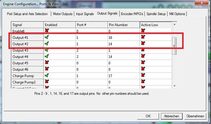
8 Outputs Like the input port, each output port is also provided with a pin number and an associated * (output). example X32- is Number 6 = Port2/Pin6 and X32-2 is Number 6* = Port2/Pin6 For 5V sensors, relays or similar loads you can put a bridge of 5V on the respective pin number, so you can use a power supply. For switching max 50mA per output are available. If you need higher currents for switching you can connect inexpensive relay modules. You can connect to any pin without * a direct voltage, max to 30V. 8


9 Integrate Outputs in Mach3 The Port Number and the Pin Number are used, the hook at enabled to enable output 9


10 Set Axes in Mach3/UCCNC These are fixed values that should not be changed. 0
11 Driver Connection

12 Set spindle Port / Pin is the analog output for the spindle speed A VFD frequency inverter for the analogue signal can be connected to the spindle output. Via jumper -2 = 5V or bridge 2-3 = 0V output signal at bridge The Potentiometer R3 should not be adjusted he is set so that at 5V PWM output from the PC comes a 0V analog signal 2

13 Spindle direction 3


14 CW (clockwise) or CCW (counterclockwise) are switchable relay outputs. 4

15 Spindle in UCCNC 5

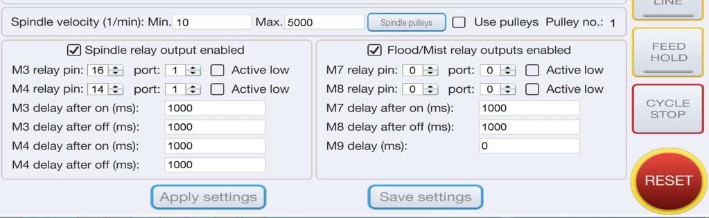
16 Relaisoutput There are 4 Relay Outputs up to 230V / max 0A (2,2KW at 230V) available PORT 2 Pin,4,6 oder 7 Attention: do not connect switching power supplies because they have a very high inrush current, the relay contacts may be defective 6
17 Statusdisplay 7


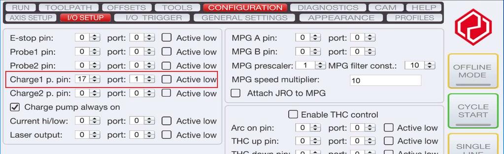
18 This setting can be enabled or disabled Charge Pump If the jumper is set to /2 the board will be activated without protection and all will remain Tensions and controls are maintained even if Mach3 makes a reset. If the jumper is set to 2/3, the breakout board will be controlled by Mach3 via the 2.5Khz signal. That is, only after the reset of Mach3 is deactivated, the board is active. All components are supplied with 5V or 2V. For this you have to make the following settings in Mach3: 8
19 9
Breakoutboard for ESS Smoothstepper
 Breakoutboard for ESS Smoothstepper Operation Manual All rights to these operating instructions remain with cnc-technics. Texts, information and illustrations of these operating instructions may not be
Breakoutboard Rev.2 for Estlcam
 Breakoutboard Rev.2 for Estlcam 1 Stefan Gemeinert,Frühlingstrasse 8 85253 Erdweg Operation Manual All rights to these operating instructions remain with cnc-technics. Texts, information and illustrations
USER S MANUAL VER.2. C76- MULTIFUNCTION CNC BOARD Rev. 1.4
 USER S MANUAL VER.2 C76- MULTIFUNCTION CNC BOARD Rev. 1.4 MARCH 2018 User s Manual Page i USER'S MANUAL TABLE OF CONTENTS Contents Page # 1.0 FEATURES... 1 2.0 I/O SPECIFICATIONS... 2 3.0 BOARD DESCRIPTION...
USER S MANUAL. M16 POKEYS MOTION MOTHERBOARD Rev. 1.1 JUNE 2016.
 USER S MANUAL M16 POKEYS MOTION MOTHERBOARD Rev. 1.1 JUNE 2016. USER'S MANUAL TABLE OF CONTENTS Page # Contents 1.0 OVERVIEW... 1 2.0 FEATURES... 1 3.0 BOARD DESCRIPTION... 2 4.0 SPECIFICATIONS... 2 4.1
USER S MANUAL. C32- DUAL PORT MULTIFUNCTION CNC BOARD Rev. 4
 USER S MANUAL C32- DUAL PORT MULTIFUNCTION CNC BOARD Rev. 4 August, 2012 USER'S MANUAL TABLE OF CONTENTS Page # 1.0 FEATURES... 1-1 2.0 SPECIFICATIONS... 2-3 3.0 BOARD DESCRIPTION... 3-4 4.0 FUNCTIONAL
USER S MANUAL. C11S- MULTIFUNTCION CNC BOARD Rev. 1.2
 USER S MANUAL C11S- MULTIFUNTCION CNC BOARD Rev. 1.2 SEPTEMBER 2014 User s Manual Page i TABLE OF CONTENTS Page # 1. Overview... 1 2. Features... 1 3. Specifications... 3 4. BOARD DESCRIPTION... 4 5. Special
PP-BOB2-V2.0 PARALLEL PORT BREAKOUT BOARD
 PP-BOB2-V2 PARALLEL PORT BREAKOUT BOARD Document: Operation Manual Document #: T18 Document Rev: 1.0 Product: PP-BOB2-V2.0 Product Rev: 1.0 Created: October, 2015 THIS MANUAL CONTAINS INFORMATION FOR INSTALLING
HDBB Breakout board user s manual
 HDBB Breakout board user s manual The HDBB breakout board was designed to use with our Whale2(-T)*, Whale3, Mammut* and Dugong servo drives or with any other third party stepper or servo drives which using
USER S MANUAL VER.1. C11G- MULTIFUNTCION CNC BOARD Rev. 9
 USER S MANUAL VER.1 C11G- MULTIFUNTCION CNC BOARD Rev. 9 MARCH, 2017 User s Manual Page i USER'S MANUAL TABLE OF CONTENTS Contents Page # 1.0 OVERVIEW... 1 2.0 FEATURES... 1 3.0 SPECIFICATIONS... 2 4.0
USER S MANUAL. C11- MULTIFUNTCION CNC BOARD Rev. 9.9
 USER S MANUAL C11- MULTIFUNTCION CNC BOARD Rev. 9.9 FEBRUARY, 2015 User s Manual Page i TABLE OF CONTENTS Page # 1. Overview... 1 2. Features... 1 3. Specifications... 3 4. BOARD DESCRIPTION... 4 5. Special
PLCM-B1 Breakout board for PLCM-E3/E3p controller
 www.purelogic.ru User manual CONTENTS: 1. General information... 2 2. Delivery set... 2 3. Technical specifications... 3 4. Key features... 4 5. Sockets purpose and indication... 6 6. Connection... 11
PP-BOB2-V1.0 PARALLEL PORT BREAKOUT BOARD
 PP-BOB2-v1 PARALLEL PORT BREAKOUT BOARD Document: Operation Manual Document #: T17 Document Rev: 2.0 Product: PP-BOB2-v1.0 Product Rev: 1.0 Created: March, 2013 Updated: Dec, 2014 THIS MANUAL CONTAINS
USER S MANUAL. C35S- QUICK SETUP BREAKOUT BOARD Rev. 1.3
 USER S MANUAL C35S- QUICK SETUP BREAKOUT BOARD Rev. 1.3 FEBRUARY, 2015 USER'S MANUAL TABLE OF CONTENTS Page # Contents 1.0 OVERVIEW... 1 2.0 FEATURES... 1 3.0 SPECIFICATIONS.... 2 4.0 BOARD DESCRIPTION...
IO3-R2 BREAKOUT BOARD
 IO3-R2 BREAKOUT BOARD DESCRIPTION Breakout board IO3-R2 (Revision R2) has digital buffer for STEP/DIR/ENA command signals and as such it is particularly suitable for the connection up to 4 microstep drives
Apollo I Breakout Board User s Manual
 MACHMOTION Apollo I Breakout Board User s Manual 1/14/2012 Everything you need to know to set up and use your Apollo I Breakout Board. MachMotion Version 1.0.1 2 P a g e M a c h M o t i o n Copyright 2012,
AXBB-E ethernet motion controller and breakout board user's guide
 AXBB-E ethernet motion controller and breakout board user's guide Version of this document: 1.0002 1/29 Contents 1.Description of the AXBB-E device. 2.Safety notes. 3.Physical installation of the device.
Manual 5 Axis CNC Interface Breakout Board Model#-DB25-1R5AM
 Manual 5 Axis CNC Interface Breakout Board Read this manual carefully before making connections to the board. Store this manual away for further reference. Safety Notes: The electronics of the control
C23- DUAL PORT MULTIFUNCTION CNC BOARD Rev. 3.1
 C23- DUAL PORT MULTIFUNCTION CNC BOARD Rev. 3.1 User manual Rev. 2 1. Overview This card has been designed to provide a flexible interface and functions to computer CNC projects, by using the parallel
UB1. Owner s manual. Doc E1.5Rev0 (8/23/2017) for PCB ver Page 1
 for PCB ver Page 1") UB1 Owner s manual Doc E1.5Rev0 (8/23/2017) for PCB ver 1.5 www.cncroom.com Page 1 Introduction It is perhaps well understood that in an industrial environment, personal computers, motion control boards
UB1 Owner s manual Doc E1.5Rev0 (8/23/2017) for PCB ver 1.5 www.cncroom.com Page 1 Introduction It is perhaps well understood that in an industrial environment, personal computers, motion control boards
USER S MANUAL. C33 - MULTIFUNCTION ROUTER BOARD BOARD Rev. 4
 USER S MANUAL C33 - MULTIFUNCTION ROUTER BOARD BOARD Rev. 4 June 2013 USER'S MANUAL TABLE OF CONTENTS Page # Contents 1.0 OVERVIEW... 3 2.0 FEATURES... 3 3.0 SPECIFICATIONS... 4 4.0 FUNCTIONAL BLOCK DIAGRAMS...
C33- MULTIFUNCTION ROUTER BOARD Rev. 2
 C33- MULTIFUNCTION ROUTER BOARD Rev. 2 User manual Rev. 1 1. Overview This card provides an easy way of interfacing your router based spindle with your steeper motor driver board. This board includes a
C11G- MULTIFUNTCION CNC BOARD Rev. 8.2
 C11G- MULTIFUNTCION CNC BOARD Rev. 8.2 User manual Rev. 2 1. Overview This card has been designed to provide a flexible interface and functions to your computer projects, by using the parallel port control
3-Axis Stepper Drive Datasheet MX3660
 3-Axis Stepper Drive Datasheet MX3660 3-Axis Stepper Drive + Breakout Board, 20-60VDC, 6A Peak Version 0.0.2 http://www.leadshine.com Features Three individual stepper drive boards Suitable for NEMA17
GUIDE TO SP STARTER SHIELD (V3.0)
") OVERVIEW: The SP Starter shield provides a complete learning platform for beginners and newbies. The board is equipped with loads of sensors and components like relays, user button, LED, IR Remote and
OVERVIEW: The SP Starter shield provides a complete learning platform for beginners and newbies. The board is equipped with loads of sensors and components like relays, user button, LED, IR Remote and
C35- QUICK SETUP BREAKOUT BOARD Rev. 1.1
 C35- QUICK SETUP BREAKOUT BOARD Rev. 1.1 User manual Rev. 1 1. Overview This card provides an easy way of interfacing your inputs and outputs from the parallel port. It provides terminals and RJ45 for
X CNC Control with Mitsubishi Drives and Servo Motors Setup Guide
 X15-350-04 CNC Control with Mitsubishi Drives and Servo Motors Setup Guide 2007 Mach Motion MachMotion X15-350-04 CNC Control with: Mitsubisi Drives Mitsubisi Motors 24V Power Supply IO6 Breakout Board
EN006 - DigiSpeed Selection Chart
 - Selection Chart The range is designed to allow you to control the speed of your spindle motor from your CNC software. They do this by accepting a control signal from the CNC software and converting to
BBC Series. 6 Axis Breakout Board. User Manual Doc BBCM Rev All Rights Reserved
 BBC Series 6 Axis Breakout Board with VFD Support User Manual www.machdrives.com Doc BBCM Rev 1.0 2017 All Rights Reserved Notice This guide is delivered subject to the following conditions and restrictions:
UNIPORT V2. Uniport V2
 UNIPORT V2 Uniport V2 USB powered Parallel port interconnection board with optical isolated inputs, buffered outputs, charge pump interlock and power relays Specification Full optical isolation of all
DigiSpeed-SD DC-06. Isolated Control Voltage Generator User s Guide. DigiSpeed-SD PCB Ver:3.0 Mach3 Ver: 2.+ DigiSpeed-SD - Users Guide Page 1
 DigiSpeed-SD - Users Guide Page 1 Updated: 4 th May 2011 DigiSpeed-SD DC-06 Isolated Control Voltage Generator User s Guide DigiSpeed-SD PCB Ver:3.0 Mach3 Ver: 2.+ DigiSpeed-SD - Users Guide Page 2 Homann
C10- PARALLEL PORT INTERFACE CARD Rev. 8
 C10- PARALLEL PORT INTERFACE CARD Rev. 8 User manual Rev. 1 1. Overview This card provides an easy way of interfacing your inputs and outputs from you parallel port. It provides terminals for the connections
CNC4PC. MULTIFUNCTION CNC BOARD Rev2
 CNC4PC Manual MULTIFUNCTION CNC BOARD Rev2 Overview This card has been designed to provide a flexible interface and functions to your computer projects, by using the parallel port control software. This
User Manual of 5Axis Breakout Board
 WWW.VALLDER.COM User Manual of 5Axis Breakout Board Safety Statement Vallder Ltd is not liable or responsible for any accidents, injuries, equipment damage, property damage, loss of money or loss of time
CNC4PC. C11G - MULTIFUNCTION CNC BOARD Rev. 5.4
 CNC4PC Manual C11G - MULTIFUNCTION CNC BOARD Rev. 5.4 Overview This card has been designed to provide a flexible interface and functions to your computer projects, by using the parallel port control software.
Manual. Model#-DB25M-3R6A. 6 Axis CNC Interface Breakout Board. Lastest update : Feb Store this manual away for further reference.
 Manual 6 Axis CNC Interface Breakout Board Model#-DB25M-3R6A Lastest update : Feb 2016 Read this manual carefully before making connections to the board. Store this manual away for further reference. Safety
UNIPORT V3. C R H Electronics Design
 UNIPORT V3 V C R H Electronics Design Uniport V3 USB powered Parallel port interconnection board with optical isolated inputs, buffered outputs, charge pump interlock and power relays By C R Harding Specification
ACORN User Guide For Revision (Aka Acorn_rev3) Updated 1/23/17
 Updated 1/23/17") ACORN User Guide For Revision 171025 (Aka Acorn_rev3) Updated 1/23/17 Overview ACORN is technically a breakout board for the BeagleBone Green or BeagleBone Black embedded computer. The remainder of this
ACORN User Guide For Revision 171025 (Aka Acorn_rev3) Updated 1/23/17 Overview ACORN is technically a breakout board for the BeagleBone Green or BeagleBone Black embedded computer. The remainder of this
USER S MANUAL. CNC Servo Stepper Motor Control Box CH4EV12-1 Rev. 1
 USER S MANUAL CNC Servo Stepper Motor Control Box CH4EV12-1 Rev. 1 January, 2013 i USER'S MANUAL TABLE OF CONTENTS Page # Contents 1.0 FEATURES... 1 2.0 SPECIFICATIONS... 2 3.0 SYSTEM REQUIREMENTS... 2
UIM2901-5A. Page 2. UI Robot Technology Co. LTD M EN. Please pay attention to the following before using the UIROBOT products:
 User Manual MACH3 Breakout Board Please pay attention to the following before using the UIROBOT products: UIROBOT products meet the specification contained in their particular Data Sheet. UIROBOT will
PLCIO2 Programmable Logic Controller Updated 3/26/10
 Overview: PLCIO2 Programmable Logic Controller Updated 3/26/10 PLCIO2 is a programmable logic controller which provides: 35 Inputs (bipolar, with a choice of 5 or 24) 39 Outputs (20SPST, 2 SPDT, 17 open
Apollo III INSTALLATION MANUAL
 Apollo III INSTALLATION MANUAL 2 P a g e 5/1/14 N0112 This manual covers the setup and configuration of the Apollo III motion controller connected to the control using Mach3. Formatting Overview: Menus,
Centroid ACORN CNC controller Specification and Use Guide Updated 8/3/17. Overview
 Centroid ACORN CNC controller Specification and Use Guide Updated 8//7 Overview ACORN is technically a CNC control breakout board for the BeagleBone Green or BeagleBone Black embedded computer the Beagle
USER S MANUAL. CNC Stepper Motor Control Box CS3EA4-1 Rev. 1
 USER S MANUAL CNC Stepper Motor Control Box CS3EA4-1 Rev. 1 April, 2012 USER'S MANUAL TABLE OF CONTENTS Page # Contents 1.0 FEATURES... 2 2.0 SPECIFICATIONS... 3 3.0 SYSTEM REQUIREMENTS... 3 4.0 WARNING...
Hardware Manual CNC760
 Hardware Manual CNC760 Revision 3 6 December, 2017 Released Copyright 2017 by Eding CNC History: Revision Date Author 1 22-5-2017 AB 2 23-6-2017 AB 3 6-12-2017 AB Revision overview: Revision Remarks 1
UCBB dual port breakout board user's manual
 UCBB dual port breakout board user's manual 1/14 Contents 1 Features 2 Dimensions 3 Connectors 3.1 Screw terminals 3.2 IDC ports 3.3 Powering 3.4 Outputs 3.5 Inputs 4 LED indicators 5 Example connections
C4 SAFETY CHARGE PUMP BOARD Rev. 6.2
 C4 SAFETY CHARGE PUMP BOARD Rev. 6.2 User manual Rev. 1 1. Overview. This board takes advantage of Mach ability to send a specific frequency through one of the pins of the parallel port when the program
Comprehensive support USB hot-swappable, USB connection at any time to monitor the state, Mach3 work
 USB motion control card installation manual The card features: Supports all versions of Mach3, including the latest version of Mach3 R3.042.040. Supports all versions of Windows, including the latest version
Pulsafeeder Technical Bulletin
 Topic VFD Vector Programming and Connections Pulsafeeders VFD Vector provides control capability with a 3 phase motor. This control can be either local at the VFD or externally from a control source. This
TurboTaig Instruction Manual
 TurboTaig Instruction Manual Version: 2.2 Peter Homann 20 View St Highett 3190 homann@smartchat.net.au http://people.smartchat.net.au/~homann 1 Table of Contents Table of Contents... 2 Introduction...
MaxStepper Serial Step and Direction Pulse Generator. User Manual
 MaxStepper Serial Step and Direction Pulse Generator User Manual 2007 Kellyware 9/20/2007 WWW.KELLYWARE.COM Table of Contents Table of Contents... 2 Parts List... 3 Key Features... 3 Introduction... 4
Operating instructions CNC Motion Controller: AC-CNC2017-2S (REV03)
") Operating instructions CNC Motion Controller: AC-CNC2017-2S (REV03) www.arduinoclub.de Dear customer, thank you for choosing our product. All our products are checked and subject to the controls of our
Operating instructions CNC Motion Controller: AC-CNC2017-2S (REV03) www.arduinoclub.de Dear customer, thank you for choosing our product. All our products are checked and subject to the controls of our
CPU5A Economy Series USBCNC software included. Features
 CPU5A Economy Series 125 KHz step frequency, 4 axes. Card size 100x100mm. USB 2.0 connection. 100 Mbit Ethernet connection (*). 5 Status LED's. Full 4 axes interpolation (*). 7 Standard CNC outputs. 0-10V
Datasheet MX Axis Stepper Drive with Breakout Board & I/O s. Version1.0
 Datasheet MX3660 3-Axis Stepper Drive with Breakout Board & I/O s Version1.0 1. Features Power up to 3 stepper motors of NEMA 17, 23, 24, or 34 Sophisticated stepper motor control based on latest DSP technology
Preliminary Datasheet MX Axis Stepper Drive with Breakout Board & I/O s. Preliminary V1.0
 Preliminary Datasheet MX4660 4-Axis Stepper Drive with Breakout Board & I/O s Preliminary V1.0 Features Power up to 4 stepper motors of NEMA 17, 23, 24, or 34 Sophisticated stepper motor control based
Ether-Mach Mach3 Plugin Guide
 Ether-Mach Mach3 Plugin Guide Ethernet Motion Controller for Artsoft's Mach3 CNC. Features Connects over a dedicated 100 Mbps Ethernet connection. Smooth motion on 6 coordinated axes plus a spindle motor.
E101 - Strain Gauge Transducer Display Module. Contents
 E101 - Strain Gauge Transducer Display Module Contents Torque Transducer Display Interface: TSE3249R Strain Gauge Transducer Display Interface [E101] Operating Guide: TSE2097V (Includes Introduction, Description
DigiSpeed-XL DC-02. Isolated Control Voltage Generator User s Guide. DigiSpeed-XL PCB Ver:6.0 Firmware Ver: 6.x Mach3 Ver: 1.84
 DigiSpeed-XL - Users Guide Page 1 Updated: 14. September 2007 DigiSpeed-XL DC-02 Isolated Control Voltage Generator User s Guide DigiSpeed-XL PCB Ver:6.0 Firmware Ver: 6.x Mach3 Ver: 1.84 DigiSpeed-XL
EC X17 - CNC Ethernet Stepper Controller
 EC X17 - CNC Ethernet Stepper Controller Features This 4 Axis CNC Stand-Alone stepper Controller ensures smooth and accurate fast motion Command and program loading is made from the EC Watch software via
Hardware Installation Manual MX Axis Stepper Drive with Breakout Board & I/O s
 Hardware Installation Manual MX3660 3-Axis Stepper Drive with Breakout Board & I/O s Version 1.0 11 / 2013 Hardware Manual for MX3660 3-Axis Stepper Drive with Breakout Board & I/O s ii Notice Read this
User Manual. For 3rd Generation. 5 Axis Standard & Professional Breakout Board Set
 The 3 rd Generation 5 Axis Breakout Board Set User Manual For 3rd Generation 5 Axis Standard & Professional Breakout Board Set Attention: Please read the manual carefully before using the products! Email:
Current plugin version: V1.028
 UC300-5LPT USB CNC motion controller to use with MACH3 software Current plugin version: V1.028 Contents: 1. Product description and background of working. 2. Pinouts a. Connectors placement and types.
C10S- PARALLEL PORT INTERFACE CARD Rev. 1.4
 USER S MANUAL VER.1 C10S- PARALLEL PORT INTERFACE CARD Rev. 1.4 SEPTEMBER, 2016 User s Manual Ver.1 Page i USER'S MANUAL TABLE OF CONTENTS Page # 1. OVERVIEW... 1 2. FEATURES... 1 3. SPECIFICATIONS...
AN004 Using the PMDX-126 s Error Input and Restart Output with Geckodrive Servo Drivers and Mach3 CNC Software
 1.0 Overview This application note describes how to connect the to the Geckodrive G320//G340 step servo driver s ERR/RST terminal to allow the to detect a Geckodrive error (fault) state and to reset the
UCCNC software installation and user's guide
 UCCNC software installation and user's guide Version of this software manual: 1.0042 Software version: 1.2047 Supported motion controllers: UC100 UC300ETH 5LPT UC300 5LPT UC300ETH M44 UC300 M44 UC300ETH
Datasheet MX Axis Stepper Drive with Breakout Board & I/O s. Version
 Datasheet MX4660 4-Axis Stepper Drive with Breakout Board & I/O s Version 1.0 http://www.leadshine.com http://www.leadshineusa.com 2014 Leadshine Technology Co., Ltd. Notice This document is not for use
Profi4 Main Board Manual
 Profi4 Main Board Manual A. Scope of application It is used to run the signal processing of the host computer ( LPT port ), with MACH 3 CNC system software, and the peripheral machine dynamic electrical.
C-Series C142 Machine Controller Eurocard DIN Packaged Systems
 C-Series C142 Machine Controller Eurocard DIN Packaged Systems FEATURES: Available as 2- or 3-axes CNC Controller Remote START/STOP/RESET Bidirectional serial communication at up to 192 baud 32K of on-board
DC3IOB Revision User Guide Updated 3/29/10. Overview
 Revision 080910 User Guide Updated 3/29/10 Overview The is a three axis DC brush motor drive with an integrated PLC. A range of motor drive currents are selectable with jumper blocks. The integrated PLC
G540 User Manual. Date Modified: March 5, 2012 Page 1 of 10
 G540 User Manual Date Modified: March 5, 2012 Page 1 of 10 DIMENSIONS PHYSICAL AND ELECTRICAL RATINGS Minimum Maximum Units Supply Voltage 18 50 VDC Motor Current 0 3.5 A Power Dissipation 1 13 W Short
RTK4 Logic Controller User Manual For RTK4L Revision Revised
 RTK4 Logic Controller User Manual For RTK4L Revision 120326 Revised 6-20-12 RTK4 Features Application: PLC and Third Party Drive Interface Number of Axis Drive Interfaces: 5 Axis DAC Resolution: 16 bits
C50- PARALLEL PORT INTERFACE CARD Rev. 1
 C50- PARALLEL PORT INTERFACE CARD Rev. 1 User manual 1. Overview This card provides an easy way of interfacing your inputs and outputs from you parallel port. It provides terminals for the connections
uservo box instruction manual
 Safety notes uservo box instruction manual Every machine controlled by computer (PC) can be really dangerous for human life and health. Comply with bolow rules and use Your common sense while working with
G540 4-AXIS DRIVE REV 4: MAY 28, 2010
 Thank you for choosing to purchase the G540 4-Axis Drive System. If you are dissatisfied with it for any reason at all within two weeks of its purchase date, you may return it for a full refund provided
RoboClaw 2x30A Dual Channel Motor Controller
 RoboClaw 2x30A, 34VDC Dual Channel Brushed DC Motor Controller Version 2.2 (c) 2016 Ion Motion Control. All Rights Reserved. Feature Overview: 60 Amps Peak Per Channel Channel Bridging Supported Dual Quadrature
USER S MANUAL VER.1. C10D- PARALLEL PORT INTERFACE CARD BOARD Rev. 1
 USER S MANUAL VER.1 C10D- PARALLEL PORT INTERFACE CARD BOARD Rev. 1 MARCH 2018 User s Manual Page i USER'S MANUAL TABLE OF CONTENTS Contents Page # 1.0 OVERVIEW... iii 2.0 FEATURES... iii 3.0 SPECIFICATIONS...
MachBob2 (MB2) Owner Instruction manual. Doc E1.2 (22/03/59) Page 1
 Owner Instruction manual. Doc E1.2 (22/03/59) Page 1") MachBob2 (MB2) Owner Instruction manual Doc E1.2 (22/03/59) www.cncroom.com Page 1 Introduction It is known that the environment in the industry often have interference from electrical power such as motors,
MachBob2 (MB2) Owner Instruction manual Doc E1.2 (22/03/59) www.cncroom.com Page 1 Introduction It is known that the environment in the industry often have interference from electrical power such as motors,
SHIELD-MD10 Cytron 10A Motor Driver Shield
 SHIELD-MD10 Cytron 10A Motor Driver Shield User's Manual V1.0 October 2012 Created by Cytron Technologies Sdn. Bhd. All Right Reserved 1 Index 1. Introduction 3 2. Packing List 4 3. Product Specification
Programmable Logic Controllers
 Programmable Logic Controllers PLC Evaluation Board used in ECE 461 What is a PLC? Programmable Logic Controllers (PLC's) are microprocessor devices much like the PIC microcontroller. Their function is
VSDEPI VSD-E Parallel Interface breakout board Manual Ver. 0.9
 Introduction VSD-E Parallel interface is a breakout board designed to ease connection of up to four VSD-E drives in single D-Sub 25 connector. Connector pin-out has been designed for step/dir operation
Explorer V1.20. Features
 V1.20 Multi-function USB I/O Expander and Controller Features Dual h-bridge 1.3A motor drive with PWM speed control 4.6V to 10.8V input range USB communication 4x digital inputs 2x analogue inputs 7x 100mA
G540 MANUAL MULTIAXIS STEP MOTOR DRIVE
 G540 MANUAL MULTIAXIS STEP MOTOR DRIVE PRODUCT DIMENSIONS PHYSICAL AND ELECTRICAL RATINGS Minimum Maximum Units Supply Voltage 18 50 VDC Motor Current 0 3.5 A Power Dissipation 1 13 W Short Circuit Trip
- Electronic Limit Switches - Very Accurate - Easy to use - Robust - Dependable - High Resolution - Non Contact Measurement - Wide Temp.
 1-30-2018 EPS 02 Operating Instructions RACO Electronic Position Sensor - Electronic Limit Switches - Very Accurate - Easy to use - Robust - Dependable - High Resolution - Non Contact Measurement - Wide
USER S MANUAL. C4 SAFETY CHARGE PUMP BOARD Rev. 6.2
 USER S MANUAL C4 SAFETY CHARGE PUMP BOARD Rev. 6.2 March 2013 USER'S MANUAL TABLE OF CONTENTS Page # Contents 1.0 OVERVIEW... 1 2.0 FEATURES... 1 3.0 SPECIFICATIONS... 2 4.0 SIMPLIFIED SCHEMAT... 2 5.0
USER S MANUAL C10- PARALLEL PORT INTERFACE CARD
 USER S MANUAL C10- PARALLEL PORT INTERFACE CARD Rev. 10 June, 2012 USER'S MANUAL TABLE OF CONTENTS Page # 1. OVERVIEW... 1 2. FEATURES... 1 3. SPECIFICATIONS... 2 4. BOARD DESCRIPTION... 3 Using configuration
Datasheet MX Axis Stepper Drive with Breakout Board & I/O s. Version
 Datasheet MX3660 3-Axis Stepper Drive with Breakout Board & I/O s Version 1.1 http://www.leadshine.com http://www.leadshineusa.com 2013 Leadshine Technology Co., Ltd. Notice This manual is not for use
UNIVERSAL MOTION INTERFACE (UMI) ACCESSORY
 ACCESSORY") USER GUIDE UNIVERSAL MOTION INTERFACE (UMI) ACCESSORY Introduction This user guide describes how to use the UMI-A, UMI-Flex, and UMI-Flex accessories. The UMI products are connectivity accessories you
USER GUIDE UNIVERSAL MOTION INTERFACE (UMI) ACCESSORY Introduction This user guide describes how to use the UMI-A, UMI-Flex, and UMI-Flex accessories. The UMI products are connectivity accessories you
VSDEPI VSD-E/XE Parallel Interface breakout board Manual Ver. 1.1
 Introduction VSD-E/XE Parallel interface is a breakout board designed to ease connection of up to four VSD-E/XE drives in single D-Sub 25 connector. Connector pin-out has been designed for step/dir operation
RTK3 Logic Controller User Manual Revised
 RTK3 Logic Controller User Manual Revised 6-24-08 1 of 16 svn://software/hardware/rtk3/docs/rtk3_man.doc MRR 6/24/08 9:03 AM Overview The RTK3 is intended to simplify and expedite control wiring. Centroid
请在这里输入您的公司名称
 请在这里输入您的公司名称 WWW.DDCNC.COM M DDMDTV1 MACH3 CARD Contents Chapter 1 Overview... 1 1.1 Simply Introduction... 1 1.2 Requirements of Computer... 1 1.3 Product feature... 2 1.4 Outview & Size... 3 1.5 Notes
Series LC6D/LC6C. LJ1 LG1 LC1 LX LC6D/LC6C Switches LC6C LC6D. Series LX Dedicated Stepper Motor Driver and Positioning Driver
 Series LCD To power supply Stepper Motor Driver LCD Electric Actuator Series LCC Series LX Dedicated Stepper Motor Driver and Positioning Driver Series LCD/LCC PLC Positioning unit (Not incl. To be provided
DC3IOB Revision User Guide Updated 7/12/12. Overview
 DC3IOB Revision 080910 User Guide Updated 7/12/12 Overview The DC3IOB is a three axis DC brush motor drive with an integrated PLC. A range of motor drive currents are selectable with jumper blocks. The
MAC3-USBCARD-MK-Instructions 济南优本机械设备有限公司 Jinan Acctek Machinery Co.,Ltd MACH3 Suitable systems:mach3
 Suitable systems:mach3-1 - MAC3-USBCARD-MK-Instructions Model: XHC-MK4:With USB interface, 4-axis motion control card XHC-MK6:With USB interface, 6-axis motion control card MACH3 - 2 - Features: Fully
PLCM-E1b CNC Ethernet controller
 PLCM-E1b CNC Ethernet controller INSTRUCTION MANUAL 01. General information 02. Delivery set 03. Technical features 04. Main connectors and indicators 05. Software installation 06. Terms of Warranty 2
Installation & Operation Guide
 Installation & Operation Guide Direct Digital VAV Controllers KMD-7001/7051 - VAV Terminal Units KMD-7002/7052 - Dual Duct VAV Units KMD-7003/7053 - Fan Induction Units 907-019-01C 1 Introduction This
DDUM CARD V1.0 Simple Description (English)
") DDUM CARD V1.0 Simple Description (English) Chapter 1 Overview 1.1 Simply Introduction 1.2 Requirements of Computer 1.3 Appearance and size of poduct 1.4 Notes and Cautions Chapter 2 Detailed Features
DDUM CARD V1.0 Simple Description (English) Chapter 1 Overview 1.1 Simply Introduction 1.2 Requirements of Computer 1.3 Appearance and size of poduct 1.4 Notes and Cautions Chapter 2 Detailed Features
PMDX-108-Output. 8-Channel Isolated Output Board for PC parallel port pins 2-9. User s Manual
 PMDX-108-Output 8-Channel Isolated Output Board for PC parallel port pins 2-9 User s Manual Date: 25 February 2010 PMDX Web: http://www.pmdx.com 9704-D Gunston Cove Rd Phone: +1 (703) 372-2975 Lorton,
Digital Servo Drive. For Brushless Motor or Brushed Motor MDSC4805 / MDSC4810 / MDSC4830 / MDSC4850. Datasheet V1.1. Jun 2, 2017
 Digital Servo Drive For Brushless Motor or Brushed Motor MDSC4805 / MDSC4810 / MDSC4830 / MDSC4850 Datasheet V1.1 Jun 2, 2017 Copyright @ Mach Motion Products, INC. 2017 All rights reserved. No part of
Section 09: Attached Optional Devices
 Section 09: Attached Optional Devices M-Function Board Use and Setup Miscellaneous Functions (M-Codes) Miscellaneous functions, or M-codes, are used to control actions other than the normal machine movement.
Novusun Controller Wiring and MACH3 Software Setup
 Novusun Controller Wiring and MACH3 Software Setup V1.0 01 2019 Open Source Mechatronics LTD 2019 Safety Statement The author of this document is not liable or responsible for any accidents, injuries,
Apollo III User Manual - Mach3
 Apollo III User Manual - Mach3 WARNING! Improper installation of this motion controller can cause DEATH, INJURY or serious PROPERTY DAMAGE. Do not attempt to install this controller until thoroughly reading