indus technologies IDEX 300 Hard Drive Switch Installation & Operation For SATA Drives
|
|
|
- Leslie Barton
- 5 years ago
- Views:
Transcription
1 indus technologies IDEX 300 Hard Drive Switch Installation & Operation For SATA Drives
2 TABLE OF CONTENTS Kit Contents... 3 Operation General... 4 Front Panel Indicators... 4 System Planning Compatibility... 5 Physical Layout... 5 Drive Functions... 5 Installation Instructions 1. Set IDEX 300 Jumpers Disconnect all Power to Computer Disconnect Existing Hard Drive(s) Mark Cables Install Second Hard Drive Optional Install Master Selector Cable Connect SATA Data Cables to Hard Drives Connect Power Cables to Hard Drives Connect Power Cables to Drive Selector Install Drive Selector Verify the Operation... 9 Terminology...10 Warranty...11 Copyright...11 page 2


3 KIT CONTENTS Qty. - Part 1 - IDEX 300 Hard Drive Selector 1 - IDEX 300 Power Cable 4 - Hard Drive Power Cables 4 - SATA Power Adaptor Cables 4 - Mounting Screws IDEX 300 IDEX Power Cable Hard Drive Power Cable SATA Power Adaptor Cable Mounting Screws page 3

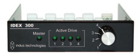
4 OPERATION General The IDEX 300 drive selector activates the selected drive at the moment when the PC power is turned on. Once the power is on any selection changes have no effect. There are two modes of operation that determine how the active drive is selected: Local: Master: The local selector switch, on the front of the drive selector, selects the drive to activate A remote Master Selector switch sends a signal to one or more IDEX units and tells the electronics which drive to select. Front Panel Indicators There are five LED lights on the face of the IDEX 300. One group of LED indicators on the front panel is labeled Active Drive, and a separate LED indicator is called Master. Only one drive can be active at a time, so only one of the four Active Drive indicators should be on. The Master light will only be on when the IDEX unit is connected to a Master Selector. Master Mode Indicator Selected / Active Drive page 4
5 SYSTEM PLANNING Compatibility The IDEX 300 hard drive switch is compatible with any computer with an open 3.5 drive bay, two or more internal SATA ports, and room to run addition cables. One SATA port is required per drive being switched. A free card slot or a 9-pin port can be used in conjunction with the Master Selector. Physical Layout Prior to installing the IDEX 300 and additional hard drives, you will need to decide which drive will physically be connected as Drive 1, 2, 3, and 4. There is no difference between switch settings, so any drive can be Drive 1, 2, 3, or 4. A simple approach is to designate the existing drive as Drive 1 and the additional drives as Drive 2, 3, and 4. Drive Functions Each drive should have a clearly defined function. Once you have decided on each drive s function you will be able to determine which drive, if any, should be set as a default ( see page 10 ). There are many different ways in which multiple drives can be used, the intent here is only to give some possibilities. Examples: Designate Drive 1 as a general purpose drive that anyone can use. Set this as the default drive. Assign different drives for different operating systems E.g. ( Drive 1 = Windows XP, Drive 2 = Windows NT, Drive 3 = Unix, Drive 4 = Linux ) Assign different drives to different users or classes Designate Drive 4 for testing. This drive could be used by all classes at different times.. Testing could include diagnosing and repairing defective software and installing new software Assign different drives to different instructors page 5
6 INSTALLATION INSTRUCTIONS These instructions assume the computer is setup for SATA only ( no IDE drives ). Static Caution: Before removing any parts from protective static bags ensure that you have taken proper precautions to prevent damage from static. A static strap should be worn at all times. 1. Set IDEX 300 Jumpers If you are using the IDEX 300 as a stand alone unit ( in Local Mode, no Master Selector ) remove all jumpers. Master Mode This mode is used when the drive selector is being controlled by a remote Master Selector. In this mode the IDEX 300 will activate the drive set by the Master Selector. If the signal from the Master Selector is not valid the logic will activate the Default Drive. Master Mode is set by placing one jumper on the Master Mode position as shown. The Local and Drive 1 default jumper settings determine what the drive selector will do if it detects an invalid pattern on the Master Selector signal. This could occur if the Master Selector is faulty or if the cable from the Master Selector is disconnected. If no jumper is placed on the Local or Drive 1 position no drive will be selected. Local Drive 1 When the jumper is place on this position, the drive is selected by the IDEX 300 and will be activated if there is a problem with the signal from the Master Selector. When the jumper is place on this position, Drive 1 will be activated if there is a problem with the signal from the Master Selector. Jumper Pins Master Mode Drive 1 Default Local Local Mode Master Mode Drive 1 Local Default Master Mode: Drive 1 Master Mode Drive 1 Local Default Master Mode: Local Select page 6


 drive into the tower securely.")
7 2. Disconnect All Power To Computer Disconnect the power cable from your computer. 3. Disconnect Existing Hard Drive Disconnect the power and data cable from the existing hard drive. 4. Mark Cables Note: All four positions on the IDEX 300 are identical and any position can be used. To simplify these instructions, position 1 & 2 are assumed. Designate one set of power and data cables as drive position one by marking the connectors on both ends of both cables with a 1. Mark the second set with a 2. This is done for simplicity in setup and to aid in any trouble-shooting later. Hard Drive Power Cable SATA Data Cable ( Not In Kit ) 5. Install Second Hard Drive Mount the your second ( third and fourth ) drive into the tower securely. A poorly mounted drive can cause excessive noise, may result in loose cables, and might reduce the life span of a hard drive due to vibration. 6. OPTIONAL Install Master Selector Jumper Cable ( Not Included In Kit ) See web site for additional installation instructions regarding installation of Master Selector. page 7

8 7. Connect SATA Data Cables To Hard Drives Connect SATA data cable #1 to hard drive #1, then connect SATA Data Cable #1 to motherboard. Repeat as required for each additional drive. 8. Connect Power Cables To Hard Drives Connect Hard Drive Power Cable #1 to hard drive #1. Repeat as required for each additional drive. 9. Connect Power Cables To Drive Selector Position the drive selector at the front of the PC so that it is ready to slide in to the drive bay. Connect the IDEX Power Cable and Hard Drive Power Cables to their respective connectors on the switch. Connect the internal PC power cable to the IDEX 300 Power In Connector Connect hard drive power cable #1 to the Drive Power Out Connector #1. Connect hard drive power cable #2 to the Drive Power Out Connector #2. Continue for Drive 3 and Drive 4. (If present) Connect the jumper cable to the Master Selector Connector ( note Pin 1 orientation ) Master Selector Connector Bus Switch Control Connector ( Not Used With SATA ) IDEX Power In Connector Drive Power Out Connector page 8
9 10. Install Drive Selector Mount IDEX 300 in drive bay using the four screws supplied. 11. Verify the Operation If the Master light is on, and you are not using a Master Selector, confirm that the Master Mode Jumper has been removed. If it has been removed, and the Master light remains on, please contact technical support for assistance. Local Set the IDEX 300 Switch to Drive 1 and turn the PC on. One indicator should be on, Drive 1.. All other indicators should be off and the PC should boot normally from Drive 1. Shutdown the PC. Set the IDEX 300 switch to Drive 2. Turn the power on. One indicator should be on, Drive 2.. All other indicators should be off and the PC should boot normally from Drive 2. Master Set the Master Selector switch to Local. Set the IDEX 300 switch to Drive 1 and turn the PC on. Two indicators should be on, Master and Drive 1.. All other indicators should be off and the PC should boot normally from Drive 1. Shutdown the PC. Set the Master Selector switch to Local. Set the IDEX 300 switch to Drive 2 and turn the PC on. Two indicators should be on, Master and Drive 2.. All other indicators should be off and the PC should boot normally from Drive 2. Shutdown the PC. Set the Master Selector switch to Drive 1. Leave the IDEX 300 switch on Drive 2. Turn the PC on. Two indicators should be on, Master and Drive 1.. All other indicators should be off and the PC should boot normally from Drive 1. If there is a problem with either drive, the most likely cause is incorrect cable connections. Check that all cables are connected correctly. If the Master light on the IDEX unit is flashing, check the master cable connections between computers and to the IDEX unit. page 9
10 TERMINOLOGY Below are definitions of terms used in this manual. Active Drive : Default Drive 1 : Default Local : Refers to the lights on the face of the IDEX 300 and the physical drive in operation A jumper pin setting that tells the IDEX 300 to select Drive 1 as the boot drive in case of a communications error from the Master Selector A jumper pin setting that tells the IDEX 300 to use the drive selected by the Local Selector as the boot drive in case of a communications error from the Master Selector Drive # : When discussing a selected drive, it will be referenced by the position on the IDEX 300. If you are on position 2 of the IDEX 300, then the drive active is Drive 2 Drive Selector : IDE : IDEX 300 : Jumpers : Local Mode : The IDEX 300 unit Acronym that stands for Integrated Drive Electronics, a type of connection for data transfer A device capable of selecting a SATA, IDE, or SCSI data device to activate at power up These are a set of pin pairs on the IDEX 300. They select a pre-programed operation A setting on the Master Selector that allows the IDEX 300 to select the drive Local Selector (Switch) : The physical rotary knob on the IDEX 300 Master Mode : Master Selector : PC : SATA : Is when the Master Selector is on a setting other than Local Mode. Selection made on the IDEX 300 has no effect A remote device that controls the drive selected by the IDEX unit Refers to a Personal Computer, or Computer Tower Acronym that stands for Serial Advanced Technology Attachment, or Serial ATA CONVENTIONS USED To clarify these instructions, the following conventions are in use throughout this manual. Parenthesis : A word in parenthesis ( ) is referring to a component, setting, or label = Active Drive Italicized : Any word in italics is referring to a proper name of a product = IDEX 300 page 10
11 LIMITED FIVE YEAR WARRANTY Indus Technologies Inc. warrants that these goods are free from defects in workmanship and materials on purchase. If the goods are defective, they will be replaced or repaired, at Indus Technologies option, without charge on return to Indus Technologies within five years from date of purchase with satisfactory proof of purchase. This warranty is only given to the original purchaser of the goods and is void if the goods have been: Damaged by negligence or accident after purchase. Used other than for the purpose for which they are intended to be used or not used in accordance with any operating instructions supplied with the goods. Adapted or repaired other than by Indus Technologies. Added to or used with other goods which may effect the integrity, performance safety or reliability of these goods. To request warranty service, you must call Indus Technologies within the warranty period. If warranty service is required, Indus Technologies will authorize return and provide return instructions. You must ship the products back to Indus Technologies in their original or equivalent packaging, prepay shipping charges, and insure the shipment or accept the risk of loss or damage during shipment. Indus Technologies will ship the repaired or replacement products to you. ( freight prepaid ). Indus Technologies owns all parts removed from repaired products. If Indus Technologies repairs or replaces a product, its warranty term is not extended. This warranty is given in place of all other warranties and assurances, whether express or implied, including but not limited to matters of quality, fitness for purpose, or merchantability and the vendor accepts no liability, under any circumstances whatsoever, for any consequential damage or loss suffered by anyone as a result of using or being unable to use this product. Certain jurisdictions have consumer protection laws which may give you additional rights. COPYRIGHT 2010, INDUS TECHNOLOGIES INC. All rights reserved worldwide. No part of this work may be reproduced or copied in any form or by any means, electronic, mechanical, photocopying, recording, scanning, digitizing, or otherwise, without the prior written consent of Indus Technologies Inc. Published January page 11
indus technologies IDEX 410 Hard Drive Switch Installation & Operation For SATA Drives
 indus technologies IDEX 410 Hard Drive Switch Installation & Operation For SATA Drives Table of Contents Kit Contents... 3 Operation General... 4 Front Panel Indicators... 4 System Planning Compatibility...
Owner s s Manual. SATA A II Aluminum Hot-Swap Systems. Macintosh, Windows, Linux 2 BAY 4 BAY 4 BAY. Rack 8 BAY. Rack
 Owner s s Manual SATA A II Aluminum Hot-Swap Systems 2 BAY 4 BAY 4 BAY Rack 8 BAY Rack Macintosh, Windows, Linux SATA (Serial ATA) Hot-Swap Drive System / Case Kit Table of Contents User Guide Page How
LPT-to-I2C SE. Hardware Reference Guide.
 LPT-to-I2C SE Hardware Reference Guide http://www.i2ctools.com/ November 1, 2008 Information provided in this document is solely for use with the LPT-to-I2C SE product from SB Solutions, Inc. SB Solutions,
Wall. No opening (Example: LA-030-W)
") Thank you very much for choosing an EIZO product. Please read this User s Manual carefully to familiarize yourself with safe and effective usage procedures. Please retain this manual for future reference.
Thank you very much for choosing an EIZO product. Please read this User s Manual carefully to familiarize yourself with safe and effective usage procedures. Please retain this manual for future reference.
Owner s s Manual. G5 SATA Double Drive Internal Mounting Kit. Apple Macintosh G5. Add 2 SATA drives to the G5
 Owner s s Manual Add 2 SATA drives to the G5 G5 SATA Double Drive Internal Mounting Kit Apple Macintosh G5 SATA (Serial ATA) 2 Internal Drive System Table of Contents User Guide Page How SATA (Serial ATA)
SATA II HDD Canister KISS DA 435 Quick Reference Guide
 SATA II HDD Canister KISS DA 435 Quick Reference Guide If it s embedded, it s Kontron 1. Table of Contents SATA II HDD Canister KISS DA 435 1. Table of Contents 1. Table of Contents... 1 2. Important Information...
Owner s s Manual. SATA A II LCD Hot-Swap Systems. Macintosh, Windows, Linux EXTERNAL SYSTEM INTERNAL 5.25 SYSTEM DUAL EXTERNAL SYSTEM
 Owner s s Manual SATA A II LCD Hot-Swap Systems EXTERNAL SYSTEM INTERNAL 5.25 SYSTEM DUAL EXTERNAL SYSTEM Macintosh, Windows, Linux SATA (Serial ATA) Hot-Swap Drive System / Case Kit Table of Contents
3-4 SAS/SATA II HDD Canister Entry version USER S MANUAL XC-34D1-SA10-0-R. Document number: MAN A
 3-4 SAS/SATA II HDD Canister Entry version XC-34D1-SA10-0-R USER S MANUAL Document number: MAN-00077-A ii Preface Important Information Warranty Our product is warranted against defects in materials and
SATA34106 SATA Drive Carrier
 SATA34106 SATA Drive Carrier User s Manual BDM-610020085 Revision A www.rtd.com ISO9001 and AS9100 Certified Accessing the Analog World SATA Drive Carrier User s Manual RTD Document Number: BDM-610020085
OCEANIC SYSTEMS MULTIPLE ENGINE DISPLAY Part Numbers: 4161 USER MANUAL
 OCEANIC SYSTEMS MULTIPLE ENGINE DISPLAY Part Numbers: 4161 USER MANUAL Document revision 1.0.0 2 of 10 1 Introduction... 2 1.1 Product features... 2 2 Unit dimentions... 4 3 Installation... 4 3.1 Unpacking
Kramer Electronics, Ltd. USER MANUAL. Model: VP-200XLN. XGA Line Amplifier / DA
 Kramer Electronics, Ltd. USER MANUAL Model: VP-200XLN XGA Line Amplifier / DA Contents Contents 1 Introduction 1 2 Getting Started 1 2.1 Quick Start 1 3 Overview 3 4 Your VP-200XLN XGA Line Amplifier /
CM17215HR 100Mb/s Fiber CM17212HR 10/100Mb/s UTP PC/104-Plus Dual Ethernet utilitymodule. User s Manual. BDM Rev. C
 CM17215HR 100Mb/s Fiber CM17212HR 10/100Mb/s UTP PC/104-Plus Dual Ethernet utilitymodule User s Manual BDM-610020066 Rev. C ISO9001 and AS9100 Certified CM17215HR 100Mb/s Fiber CM17212HR 10/100Mb/s Twisted
IDAN-RSATA-SYS104 SATA Drive Carrier
 IDAN-RSATA-SYS104 SATA Drive Carrier User s Manual BDM-610020081 Revision B www.rtd.com ISO9001 and AS9100 Certified Accessing the Analog World SATA Drive Carrier User s Manual RTD Document Number: BDM-610020081
Sun StorageTek. 1U Rackmount Media Tray Reference Guide. Sun Doc Part Number: Second edition: December 2007
 Sun StorageTek nl 1U Rackmount Media Tray Reference Guide Sun Doc Part Number: 875 4297 10 Second edition: December 2007 Legal and notice information Copyright 2007 Hewlett Packard Development Company,
Sonic Ruptor 400. User Manual
 Sonic Ruptor 400 User Manual Data herein has been verified and validated. It is believed adequate for the intended use of the instrument. If the instrument or procedures are used for purposes over and
User Guide. Control Box. RoscoLED TM.
 RoscoLED TM Control Box User Guide This guide applies to the following RoscoLED Control Box models: RoscoLED Control Box 300W/Static White (293 22250 0000) RoscoLED Control Box 400W/VariWhite (293 22260
Network Computing. RC-PCIEM201A User Manual. Version: 1.0 Date of Release:
 Network Computing RC-PCIEM201A User Manual Version: 1.0 Date of Release: 2018-01-25 RC-PCIE201A User Manual The icons are used in the manual to serve as an indication of interest topics or important messages.
MEC-SAT-M002. User s Manual
 MEC-SAT-M002 Mini PCI-e 2-port Serial ATA III board User s Manual Third Edition, February 2014 2014 Cervoz Co., Ltd. All rights reserved. Reproduction without permission is prohibited Mini PCI-e SATA Card
TB-100 ControLynx Terminal Block
 TB-100 ControLynx Terminal Block TECHNICAL MANUAL Version 1.3 September 2006 Copyright This technical manual and the equipment, firmware and software described herein are copyrighted by INTENT DIGITAL
CTI 2551-A 8-CHANNEL ISOLATED THERMOCOUPLE INPUT MODULE INSTALLATION AND OPERATION GUIDE. Version 1.3 CTI Part # * *
 CTI 2551-A 8-CHANNEL ISOLATED THERMOCOUPLE INPUT MODULE INSTALLATION AND OPERATION GUIDE Version 1.3 CTI Part #062-00305-013 *062-00305-011* 2551-AIOG 110106 $25 Copyright 2006 Control Technology Inc.
OPERATION MANUAL BO BLASTER S OHMMETER
 OPERATION MANUAL for the BO1999-10 BLASTER S OHMMETER SEE PAGE 6 FOR USER INFORMATION AND LIMITED WARRANTY RESEARCH ENERGY OF OHIO, INC. 200 East Bluegrass Drive Norwalk, OH 44857 Phone: 419-660-8832 Fax:
Card Nest Universal 12 position card nest for all K-AB cards above and all other K-AB cards.
 Installation And Operation BASIC A/B SWITCHES K-AB-D25 K-AB-M34 SCOPE OF THIS DOCUMENT This document covers the following models: K-AB-D25 K-AB-D25-R K-AB-M34 K-AB-M34-R For the purposes of clarity, all
Kramer Electronics, Ltd. USER MANUAL. Model: RC-52N. Room Controller
 Kramer Electronics, Ltd. USER MANUAL Model: RC-52N Room Controller Contents Contents 1 Introduction 1 2 Getting Started 1 3 Overview 2 4 Your RC-52N 3 4.1 The RC-52N Front Panel 3 4.2 The RC-52N Rear Panel
MCS-Spectrum. Tactile Colorist Control Surface. Users Manual
 MCS-Spectrum Tactile Colorist Control Surface Users Manual MCS-Spectrum, MCS-3800, MCS-3400 and MCS-3000 are trademarks of JLCooper Electronics. All other brand names are the property of their respective
USB C-to-SATA DriveLock User s Guide
 USB C-to-SATA DriveLock User s Guide JMR-Intelligent Computer Solutions 8960 Fullbright Avenue Chatsworth, CA 91311 DOC-0118-000A Rev. 1.6 Printed in the USA Sales/Technical Support Phone: 1-818-998-5805
Kramer Electronics, Ltd. USER MANUAL. Model: VS-4x4FW. 4x4 FireWire Switcher
 Kramer Electronics, Ltd. USER MANUAL Model: VS-4x4FW 4x4 FireWire Switcher Contents Contents 1 Introduction 1 2 Getting Started 1 2.1 Quick Start 1 3 Overview 3 4 Your FireWire Switcher 4 5 Using the FireWire
Model 7035 Clamp-On Half Rails OPERATOR S MANUAL
 Model 7035 Clamp-On Half Rails OPERATOR S MANUAL NOTE: Check ALL parts for shipping damage. If shipping damage is noted, DO NOT use. Contact medical equipment provider for further instruction. Index 1.
Kramer Electronics, Ltd. USER MANUAL. Model: VA-1DVIN. Virtual EDID
 Kramer Electronics, Ltd. USER MANUAL Model: VA-1DVIN Virtual EDID Contents Contents 1 Introduction 1 2 Getting Started 1 3 Overview 2 3.1 Defining EDID 3 4 Your VA-1DVIN Virtual EDID 3 5 Connecting the
Emulator Setup Instructions for MB91360
 Emulator Setup Instructions for MB91360 Page 1 Application Note Emulator Setup Instructions for MB91360 Fujitsu Microelectronics Europe GmbH, Microcontroller Application Group History 13 th Oct. 99 MM
Atech Flash Technology, Inc. PROExpress-7. User's Guide. Guide de l'utilisateur
 Atech Flash Technology, Inc. PROExpress-7 User's Guide Guide de l'utilisateur Congratulations 1 Congratulations on the purchase of your new PROExpress-7 media card reader/writer. PROExpress-7 is able to
DCM Digital Control Modules
 DCM Digital Control Modules TECHNICAL MANUAL Version 1.2 November 2011 Safety Precautions Caution Read Instructions: Read and understand all safety and operating instructions before using the equipment.
FlashDrive/104 User's Manual
 FlashDrive/104 User's Manual Connect Tech, Inc. 42 Arrow Road Guelph, Ontario Canada, N1K 1S6 Tel: 519-836-1291 800-426-8979 Fax: 519-836-4878 Email: sales@connecttech.com support@connecttech.com URL:
Kramer Electronics, Ltd.
 Kramer Electronics, Ltd. Preliminary USER MANUAL Model: VM-12HDCP 1:12 DVI Distributor Contents Contents 1 Introduction 1 2 Getting Started 1 2.1 Quick Start 2 3 Overview 3 3.1 About HDCP 4 3.2 Defining
TDM-170 TIMER DISPLAY
 TDM-170 TIMER DISPLAY TECHNICAL MANUAL Version 1.1 August 2016 TDM-170 Timer Display Technical Manual Safety Precautions Caution Read Instructions: Read and understand all safety and operating instructions
Instruction and Operation Manual. CRMS Contact Resistance Measurement System. Model Number Caution!
 Instruction and Operation Manual CRMS Contact Resistance Measurement System Model Number 16574-00 Caution! Be sure to read and become thoroughly familiar with the entire contents of this manual before
CM17215HR 100Mb/s Fiber CM17212HR 10/100Mb/s UTP PC/104-Plus Dual Ethernet utilitymodule. User s Manual
 CM17215HR 100Mb/s Fiber CM17212HR 10/100Mb/s UTP PC/104-Plus Dual Ethernet utilitymodule User s Manual ISO9001 and AS9100 Certified BDM-610020066 Rev. E CM17215HR 100Mb/s Fiber CM17212HR 10/100Mb/s Twisted
CM17320HR User's Manual Octal RS-232/422/485 PC/104-Plus Module
 CM17320HR User's Manual Octal RS-232/422/485 PC/104-Plus Module BDM-610020049 Rev A CM17320HR User's Manual RTD EMBEDDED TECHNOLOGIES, INC. 103 Innovation Blvd State College, PA 16803-0906 Phone: +1-814-234-8087
PMDX-105. I/O Option Riser Board User s Manual. Document Revision: 1.1 Date: 7 September 2004 PCB Revision: PCB-443A
 PMDX-105 I/O Option Riser Board User s Manual Date: 7 September 2004 PMDX Web: http://www.pmdx.com 7432 Alban Station Blvd., A105 Phone: +1 (703) 912-4991 Springfield, VA 22150-2321 USA FAX: +1 (703) 912-5849
MIC-3001/8. 3U/4U CompactPCI Enclosure for Rack Mounting. User Manual
 MIC-3001/8 3U/4U CompactPCI Enclosure for Rack Mounting User Manual Copyright The documentation and the software included with this product are copyrighted 2004 by Advantech Co., Ltd. All rights are reserved.
User s Manual. PCI Bus Expansion Adapter for PCI Bus PC-Slot EAD(PCI)BE PCI Bus Expansion Adapter for Low Profile PCI PC-Slot EAD(LPCI)BE
BE PCI Bus Expansion Adapter for Low Profile PCI PC-Slot EAD(LPCI)BE") PC-HELPER PCI Bus Expansion Adapter for PCI Bus PC-Slot EAD(PCI)BE PCI Bus Expansion Adapter for Low Profile PCI PC-Slot EAD(LPCI)BE User s Manual CONTEC CO.,LTD. Check Your Package Thank you for purchasing
PC-HELPER PCI Bus Expansion Adapter for PCI Bus PC-Slot EAD(PCI)BE PCI Bus Expansion Adapter for Low Profile PCI PC-Slot EAD(LPCI)BE User s Manual CONTEC CO.,LTD. Check Your Package Thank you for purchasing
BRG17088HR User's Manual PCI to ISA Bridge PC/104-Plus Module
 BRG17088HR User's Manual PCI to ISA Bridge PC/104-Plus Module ISO9001 and AS9100 Certified BDM-610020053 Rev D BRG17088HR User's Manual RTD EMBEDDED TECHNOLOGIES, INC. 103 Innovation Blvd State College,
RoscoLED Tape VariWhite Gaffer Kit
 User Guide PLEASE READ & SAVE THESE ORIGINAL INSTRUCTIONS RoscoLED Tape VariWhite Gaffer Kit Specifications Part No.: 2932200BICLR RoscoLED VariWhite Gaffer Kit External Dimensions: 14 L x 12 W x 5.4 H
CF15118 CompactFlash Carrier utilitymodules User s Manual
 CompactFlash Carrier utilitymodules User s Manual BDM-610020105 Rev. A CompactFlash Carrier utilitymodules User s Manual RTD Embedded Technologies, Inc. 103 Innovation Blvd. State College, PA 16803-0906
Sonorous v2.0. Installation & User Manual
 Sonorous v2.0 Installation & User Manual Audio Messaging Solutions, LLC 720 Brooker Creek Blvd., Ste. 215 Oldsmar, FL 34677 800.584.HOLD (4653) Fax: 727.785.7659 http://onholdbusiness.com info@onholdbusiness.com
PCLD-8751 PCLD User Manual
 PCLD-8751 48-Channel Opto-isolated D/I Board PCLD-8761 24-Channel Opto-isolated D/I and 24-Channel Relay Board User Manual Copyright The documentation and the software included with this product are copyrighted
CA-A480-A Elevator Controller. Reference & Installation Manual
 CA-A480-A Elevator Controller Reference & Installation Manual TABLE OF CONTENTS INTRODUCTION.................................................................. 4 Introduction.............................................................................................
Woolich Racing. USB ECU Interface User Guide
 Woolich Racing USB ECU Interface User Guide 1) Introduction This user guide covers how to use the Woolich Racing USB ECU Interface. This includes: Connecting the USB ECU Interface into the Bike Harness
Kramer Electronics, Ltd. USER MANUAL. Rack Adapter Model: RK-1
 Kramer Electronics, Ltd. USER MANUAL Rack Adapter Model: RK-1 Contents Contents 1 Introduction 1 2 Getting Started 1 3 Overview 1 3.1 RK-1 Installation combinations 2 3.1.1 Using Blank Panels 3 3.2 Recommendations
3.5 inch Hard Drive Enclosure. Model #: HDE350U. User s Manual
 3.5 inch Hard Drive Enclosure Model #: HDE350U User s Manual 2 Rev. 060811 User s Record: To provide quality customer service and technical support, it is suggested that you keep the following information
3.5 inch Hard Drive Enclosure. User s Manual
 3.5 inch Hard Drive Enclosure Model #: HDE355U User s Manual Rev. 060811 User s Record: To provide quality customer service and technical support, it is suggested that you keep the following information
ADSP-218x Family EZ-ICE Hardware Installation Guide
 ADSP-218x Family EZ-ICE Hardware Installation Guide 2000 Analog Devices, Inc. ADSP-218x Family EZ-ICE Hardware Installation Guide a Notice Analog Devices, Inc. reserves the right to make changes to or
Speaker Selectors Models SSW-L4 EX and SSW-L6 EX. User Manual. SSW-L4 EX (bottom) and SSW-L6 EX (top)
 and SSW-L6 EX (top)") Speaker Selectors Models SSW-L4 EX and SSW-L6 EX User Manual SSW-L4 EX (bottom) and SSW-L6 EX (top) Table of Contents Important Safety Precautions...2 What s Included...2 Introduction... 3 Front Panel...
Speaker Selectors Models SSW-L4 EX and SSW-L6 EX User Manual SSW-L4 EX (bottom) and SSW-L6 EX (top) Table of Contents Important Safety Precautions...2 What s Included...2 Introduction... 3 Front Panel...
CTI 2550 EIGHT CHANNEL ISOLATED ANALOG INPUT MODULE INSTALLATION AND OPERATION GUIDE. Version 2.0 CTI Part # IOG $25
 CTI 2550 EIGHT CHANNEL ISOLATED ANALOG INPUT MODULE INSTALLATION AND OPERATION GUIDE Version 2.0 CTI Part #062-00102 2452IOG 092205 $25 ii CTI 2550 Installation and Operation Guide Copyright 2005 Control
DPN-4 Duo. User Manual. 4-Port Dual-Head Displayport KVM switch with USB 2.0 and Audio Sharing
 DPN-4 Duo User Manual 4-Port Dual-Head Displayport KVM switch with USB 2.0 and Audio Sharing Access & Control up to 4 Computers from a single Workstation Made in U.S.A. www.smartavi.com 1 1-800-AVI-2131
System 9760 Matrix Bay (CM9760-MXB) Firmware Upgrade
 Firmware Upgrade") I N S T A L L A T I O N System 9760 Matrix Bay (CM9760-MXB) Firmware Upgrade CM9760-BAY-E80 C1544M (7/03) INTRODUCTION For compatibility between the System 9760 matrix bay (CM9760-MXB) and version 8.03.006
I N S T A L L A T I O N System 9760 Matrix Bay (CM9760-MXB) Firmware Upgrade CM9760-BAY-E80 C1544M (7/03) INTRODUCTION For compatibility between the System 9760 matrix bay (CM9760-MXB) and version 8.03.006
Kramer Electronics, Ltd. USER MANUAL
 Kramer Electronics, Ltd. USER MANUAL Models: VP-200NK, 1:2 High Resolution XGA DA VP-300NK, 1:3 High Resolution XGA DA VP-400NK, 1:4 High Resolution XGA DA Contents Contents 1 Introduction 1 2 Getting
MIC-3001/8. 3U/4U CompactPCI. Enclosure for Rackmounting
 MIC-3001/8 3U/4U CompactPCI Enclosure for Rackmounting Copyright Notice This document is copyrighted, 1999. All rights are reserved. The original manufacturer reserves the right to make improvements to
TOUPCAM QUICK GUIDE INSTALLATION MANUAL
 TOUPCAM QUICK GUIDE INSTALLATION MANUAL January 2013 1 WARNING! TO AVOID THE RISK OF FIREOR ELECTRICAL SHOCK. NEVER EXPOSE THIS PRODUCTTOWATEROR OPERATEIN AHIGH HUMIDITYENVIRONMENT. Keep camera away from
TSD-DA28 2x8 Balanced Line Distribution Amplifier
 2x8 Balanced Line Distribution Amplifier 1 Description The Atlas Sound 2x8 distribution amplifier is designed to provide clean, isolated signal distribution locally or to remote locations. The unit allows
Seven Channel Remote Control
 Seven Channel Remote Control Page 1 Versa7 Kit Contents The Versa7 is designed to remotely control up to seven devices, or functions. All seven functions can be controlled with the supplied four button
OPERATING AND SERVICE MANUAL. Universal Interface Device 47
 OPERATING AND SERVICE MANUAL Universal Interface Device 47 MAGNA-POWER ELECTRONICS, INC. 39 ROYAL ROAD, FLEMINGTON, NJ 08822 May 24, 2012 SAFETY NOTICE Universal Interface Device 47 (UID46) connects
TDM-150 TIMER DISPLAY
 TDM-150 TIMER DISPLAY TECHNICAL MANUAL Covers TDM-150D, TDM-150F Version 1.1 August 2016 Safety Precautions Caution Read Instructions: Read and understand all safety and operating instructions before using
IDE/SATA HDD Enclosure UNI3510U2
 IDE/SATA HDD Enclosure UNI3510U2 FCC Compliance Statement This equipment has been tested and found to comply with the limits for a Class B digital device, pursuant to part 15 of the FCC Rules. These limits
R & D SPECIALTIES SERIES 100 RO CONTROLLER USERS MANUAL. 2004, by R & D Specialties, Inc. All Rights Reserved.
 R & D SPECIALTIES 2004, by R & D Specialties, Inc. All Rights Reserved. No part of this document may be copied or reproduced in any form or by any means without the prior written permission of R & D Specialties.
Model EZ3400 EasyTouch Owner s Manual
 Model EZ3400 EasyTouch Owner s Manual 4-Function Hand-Held Wireless Remote Control IMPORTANT SAFETY INSTRUCTIONS READ AND FOLLOW ALL INSTRUCTIONS SAVE THESE INSTRUCTIONS Table of Contents SECTION I. APPLICATION...
Atlas. GPI Smart Matrix. User Manual
 Atlas GPI Smart Matrix User Manual November 22, 2017 JLCooper Atlas is a trademark of JLCooper Electronics. All other brand names are the property of their respective owners. Atlas User Manual, November
HDMI Extender over Cat5e/6
 Statement Thanks for purchasing this product, please read this user manual carefully before using this product.in the constant effort to improve our product, we reserve the right to make functions or parameters
Kramer Electronics, Ltd. USER MANUAL. Model: VM-50AN. 1:5 Audio Distributor
 Kramer Electronics, Ltd. USER MANUAL Model: VM-50AN 1:5 Audio Distributor Contents Contents 1 Introduction 1 2 Getting Started 1 2.1 Quick Start 1 3 Overview 3 4 Your Audio VM-50AN 1:5 Distributor 4 5
U-232 USB based Serial Port replacement Version 2.0 Revision
 U-232 USB based Serial Port replacement Version 2.0 Revision 5.4.24 Copyright 2005-2010, Timewave Technology Inc., All Rights Reserved WARRANTY WHO IS COVERED WHAT WE WILL DO WHAT YOU MUST DO WHAT IS NOT
AC4G-D User s Manual
 AC4G-D User s Manual Entire contents of this manual 2004 Active Cool Ltd. Ashkelon, Israel. Reproduction in whole or in part without permission is prohibited. Active Cool and AC4G-D are registered of Active
USER MANUAL. Kramer Electronics, Ltd. Models:
 Kramer Electronics, Ltd. USER MANUAL Models: VM-10FW, 1:10 FireWire Distributor/Hub VM-15FW, 1:15 FireWire Distributor/Hub VM-20FW, 1:20 FireWire Distributor/Hub Contents Contents 1 Introduction 1 2 Getting
Vibra LITE 7 Mini QUICK START GUIDE:
 Vibra LITE 7 Mini QUICK START GUIDE: Note: to SET any function, the Digit(s) that you want to set MUST BE FLASHING. TIME & CALENDAR: Set hour, minutes, seconds & date. Press the MODE button to rotate to
Kramer Electronics, Ltd. USER MANUAL. Model: RC-BT1 / BT-1. Bluetooth controller
 Kramer Electronics, Ltd. USER MANUAL Model: RC-BT1 / BT-1 Bluetooth controller Contents Contents 1 Introduction 1 2 Getting Started 1 3 Overview 1 3.1 Your BT-1 Bluetooth controller 2 4 Using the Bluetooth
Rackmount Keyboard Installation Instructions. Revision A A-0000
 Rackmount Keyboard Installation Instructions Revision A 22000200A-0000 WARRANTY The following is an abbreviated version of warranty policy for keyboard products. For a complete warranty statement, contact
DataPort 350 & 525 USB 2.0 and FireWire Enclosure User s Guide (800)
") DataPort 350 & 525 USB 2.0 and FireWire Enclosure User s Guide WWW.CRUINC.COM (800) 260-9800 TABLE OF CONTENTS PAGE Package Contents 1 Features and Requirements 2 Installation 6 Trouble Shooting 16 Technical
DataPort 350 & 525 USB 2.0 and FireWire Enclosure User s Guide WWW.CRUINC.COM (800) 260-9800 TABLE OF CONTENTS PAGE Package Contents 1 Features and Requirements 2 Installation 6 Trouble Shooting 16 Technical
XC4100 INSTALLATION/OWNER'S MANUAL AM/FM/Cassette Receiver
 XC4100 INSTALLATION/OWNER'S MANUAL AM/FM/Cassette Receiver Preparation XC4100 INSTALLATION Please read entire manual before installation. Before You Start Disconnect negative battery terminal. Consult
Contents. HP E1586A Rack Mount Terminal Panel User s Manual
 Contents HP E1586A Rack Mount Terminal Panel User s Manual Description... 5 Connecting to VXIbus Instruments... 5 Interconnect Cables... 5 Terminal Block Connections... 6 Using the Terminal Panel for Reference
Kramer Electronics, Ltd. USER MANUAL. Model: VM-2HDCP. 1:2 DVI Distributor
 Kramer Electronics, Ltd. USER MANUAL Model: VM-2HDCP 1:2 DVI Distributor Contents Contents 1 Introduction 1 2 Getting Started 1 2.1 Quick Start 2 3 Overview 3 3.1 About HDCP 3 3.2 Defining EDID 4 3.3 Recommendations
DPN 4 Duo. User Manual. 4-Port Dual-Head DisplayPort 1.2 KVM Switch with USB 2.0 and Audio Sharing
 DPN 4 Duo User Manual 4-Port Dual-Head DisplayPort 1.2 KVM Switch with USB 2.0 and Audio Sharing Access and Control Four Computers with 2 DisplayPort Monitors each Using One KVM Workstation with Two DisplayPort
OP8/16 Optoisolated Digital Input Board User's Manual
 OP8/16 Optoisolated Digital Input Board User's Manual Real Time Devices USA, Inc. Accessing the Analog World Publication No. OP16-9742 OP8/16 User's Manual REAL TIME DEVICES USA 820 North University Drive
2.5 inch Solid State Drive (SATA Type) PC-SSD2000S, PC-SSD4000S, PC-SSD8000S User s Guide CONTEC CO.,LTD.
 PC-SSD2000S, PC-SSD4000S, PC-SSD8000S User s Guide CONTEC CO.,LTD.") 2.5 inch Solid State Drive (SATA Type) PC-SSD2000S, PC-SSD4000S, PC-SSD8000S User s Guide CONTEC CO.,LTD. Thank you for purchasing the CONTEC PC-SSD-S Series. accordance with 2.5-inch SATA standard. described
2.5 inch Solid State Drive (SATA Type) PC-SSD2000S, PC-SSD4000S, PC-SSD8000S User s Guide CONTEC CO.,LTD. Thank you for purchasing the CONTEC PC-SSD-S Series. accordance with 2.5-inch SATA standard. described
Data Capture Module OnBoard Weighing Data Capture Operator s Manual
 Data Capture Module OnBoard Weighing Data Capture Operator s Manual Canada NORAC Systems International Inc. TOLL FREE: 1-800-667-3921 (306) 664-6711 SHIPPING ADDRESS: 3702 Kinnear Place Saskatoon, SK S7P
FWA-6280A User Manual 1. FWA-6280A User Manual
 1 Copyright Notice This document is copyrighted, 2005. All rights are reserved. The original Manufacturer reserves the right to make improvements to the products described in this manual at any time without
SmartBoom PRO PHS-SB100-4F, PHS-SB100-5M, PHS-SB100-U, PHS-SB200-4F, PHS-SB200-5M, PHS-SB200-U. Operating Manual
 SmartBoom Operating Manual PRO PHS-SB100-4F, PHS-SB100-5M, PHS-SB100-U, PHS-SB200-4F, PHS-SB200-5M, PHS-SB200-U Thank You We at Pliant Technologies, LLC want to thank you for purchasing the SmartBoom PRO
FlashDrive/104 User's Manual
 FlashDrive/104 User's Manual Connect Tech, Inc. 42 Arrow Road Guelph, Ontario Canada, N1K 1S6 Tel: 519-836-1291 800-426-8979 Fax: 519-836-4878 Email: sales@connecttech.com support@connecttech.com URL:
Bluetooth USB Adapter TALUS. User Guide
 Bluetooth USB Adapter TALUS User Guide Revision 0.1 1 User Guide for the TALUS Revision 1.0.1 Firmware version 1.0.X Printed in Korea Copyright Copyright 2008, SystemBase Co., Ltd. All rights reserved.
Kramer Electronics, Ltd.
 Kramer Electronics, Ltd. Preliminary USER MANUAL Model: VM-2HDCPxl 1:2 DVI Distributor Contents Contents 1 Introduction 1 2 Getting Started 1 2.1 Quick Start 2 3 Overview 3 3.1 About HDCP 3 3.2 Defining
MODEL USB-DA12-8E Eight Channel Digital to Analog Converter USER MANUAL
 10623 Roselle Street, San Diego, CA 92121 (858) 550-9559 FAX (858) 550-7322 contactus@accesio.com www.accesio.com MODEL USB-DA12-8E Eight Channel Digital to Analog Converter USER MANUAL FILE: MUSB-DA12-8E.B1h
PR301 FM/AM Pocket Radio USER MANUAL IMPORTANT! WARRANTY INFORMATION INSIDE. PLEASE READ. Trademark of TEAC Corporation JAPAN
 PR301 FM/AM Pocket Radio USER MANUAL IMPORTANT! WARRANTY INFORMATION INSIDE. PLEASE READ Trademark of TEAC Corporation JAPAN www.teac.com.au WARRANTY REGISTRATION Please keep this information for your
OPERATION MANUAL. for the BO BLASTER S OHMMETER
 OPERATION MANUAL for the BO1999-1 BLASTER S OHMMETER SEE PAGE 5 FOR USER INFORMATION AND LIMITED WARRANTY RESEARCH ENERGY OF OHIO, INC. 200 East Bluegrass Drive Norwalk, Ohio 44857 Phone: 419-660-8832
Kramer Electronics, Ltd.
 Kramer Electronics, Ltd. Preliminary USER MANUAL Model: 903 Personal Stereo Amplifier Contents Contents 1 Introduction 1 2 Getting Started 1 2.1 Quick Start 2 3 Overview 3 4 Your 903 Personal Stereo Amplifier
EASON TECHNOLOGY. IO8 & IO24 Break-Out Module
 EASON TECHNOLOGY IO8 & IO24 Break-Out Module p/n 50-00180-01 Revision1.2 Eason Technology, Inc. 7975 Cameron Dr. Bldg 300 Windsor, CA 95492 Phone (707) 837-0120 FAX (707) 837-2742 http://www.eason.com
AHA PCI-to-Fast SCSI Host Adapter. Fast SCSI Connection for High-Performance SCSI Peripherals for Pentium PCs
 R AHA-2920 PCI-to-Fast SCSI Host Adapter Fast SCSI Connection for High-Performance SCSI Peripherals for Pentium PCs Introduction This installation guide provides the instructions needed to install and
P O W E R S U P P L Y M A N U A L
 POWER SUPPLY MANUAL Congratulations on the purchase of your new Corsair power supply. This User Agreement (the Agreement ) is a legal agreement between you ( You ), and Corsair Memory, Inc. ( Corsair ).
HD-1X4-4K User Manual
 HD-1X4-4K User Manual Factor Electronics. Contact: info@factorelectronics.com 1 Thank you for purchasing this product. For optimum performance and safety, please read these instructions carefully before
VIP-812A DUAL NETWORKED STATION PORT
 ISSUE 1 VIP-812A DUAL NETWORKED STATION PORT INTRODUCTION The VIP-812A Dual Networked Station Port allows most loop start terminal devices to be connected to a managed IP-based LAN/WAN. SPECIFICATIONS
User Manual EBPC Embedded Industrial Computer Chassis for 3.5 Biscuit SBCs
 User Manual EBPC-3500 Embedded Industrial Computer Chassis for 3.5 Biscuit SBCs Copyright The documentation and the software included with this product are copyrighted 2008 by Advantech Co., Ltd. All rights
What s in the box. SUP paddle sensor. Paddle sensor mounting track. Charger. USB cable. In your Motionize SUP kit you will find:
 User's Manual 1 What s in the box In your Motionize SUP kit you will find: SUP paddle sensor Paddle sensor mounting track Charger USB cable 2 Android & ios Requirements Android 5 or newer. iphone 5 or
Kramer Electronics, Ltd. USER MANUAL. Model: VM-80HP. 1:8 Stereo Headphone Distributor
 Kramer Electronics, Ltd. USER MANUAL Model: VM-80HP 1:8 Stereo Headphone Distributor Contents Contents 1 Introduction 1 2 Getting Started 1 3 Overview 2 4 Your VM-80HP 1:8 Stereo Headphone Distributor
DOCKING STATION FOR THE APPLE 13 MacBook
 DOCKING STATION FOR THE APPLE 13 MacBook 2009 THANK YOU Thank you for purchasing the BookEndz Dock for your MacBook Computer. The purpose of the BookEndz Dock is to eliminate the hassles, headaches, wear