PIC Dev 14 Through hole PCB Assembly and Test Lab 1
|
|
|
- Darlene Margaret Powell
- 5 years ago
- Views:
Transcription

1 Name Lab Day Lab Time PIC Dev 14 Through hole PCB Assembly and Test Lab 1 Introduction: The Pic Dev 14 is a simple 8-bit Microchip Pic microcontroller breakout board for learning and experimenting with small embedded systems. Using a board like this is easier and more reliable than building the entire circuit on a breadboard. The small Microchip Pic microcontrollers use a common pinout for power and programming interfaces so this board is compatible with many different chips. Lab Requirements: 1. Demonstration of a working PIC Dev 14 board by showing blinking LED. 2. Complete the section on setting the LED current. 3. Complete the section on black box testing. About the PIC Dev 14: To get started with this lab you will need to assemble a small development board for a 14-pin PIC microcontroller. This board was designed to simplify the task of getting started with a bare microcontroller by including some minimal support circuitry. The board will be used for a number of the labs that will be performed throughout the semester. The PIC Dev 14 board provides an interface for programming 14-pin (and smaller) PIC microcontrollers in addition to an LED and trim pot for performing simple experiments. Access to all the microcontroller pins is available on two headers spaced to fit on a standard breadboard. PIC Dev 14 Assembly


2 PIC Dev 14 Schematic: PIC Dev 14 PCB files: Silkscreen and Pads Top Copper Bottom Copper
3 Setting the LED Current: While developing firmware, it is often useful to have an LED blinking at a periodic rate to show that your system is powered up and running (heartbeat indicator). The schematic shows a 560Ω Resistor in series with the LED to set the maximum current through the LED. This value was chosen to set the brightness for a specific type of LED (color, size and efficiency). The LED that you select for your board will most likely be different and require a different resistor value to get a desirable intensity. Current through the LED: I LED = V DD V f R for example I LED = = 5.9mA Most digital multimeter s (DMM) have a DIODE mode that is useful for measuring the forward voltage of a semiconductor junction at a given current. The test current is typically between 100µA and 1mA which is low enough to prevent damage to the device but high enough to get an estimate of the forward voltage. This estimate will be good enough for today s calculations. Select an LED and measure the forward voltage using the DMM: Describe your LED (shape, color, size) Measured Vf How can you tell the anode from the cathode? Calculate the resistor needed for the following LED currents assuming VDD = 5V ILED 1mA R1 = ILED5mA R1 = ILED10mA R1 = Test your LED with the approximate values above and select a resistor that gives a luminous intensity that you are happy with. Value selected for R1 Construction: Review the schematic and printed circuit board layout then collect all the parts needed to assemble the PCB. Be careful to insert the LED and 14-pin IC socket in the correct orientation. The Anode on the LED is (usually) indicated by the longer length lead and as a square shaped pad on the PCB. Pin 1 of the PIC microcontroller is also indicated with a square shaped pad. Start with the lowest laying components then work your way up to the taller parts. A video showing how to build the board is available on the class webpage.

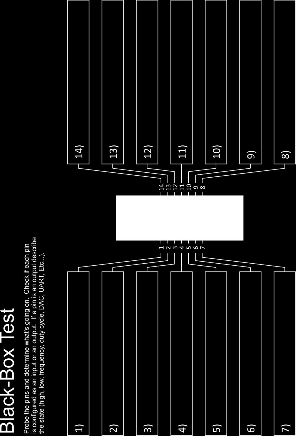
4 Connecting the power and Programming: Once your board is fully assembled inspect the solder joints and touchup any problem locations. If everything looks good, you are ready apply power to your board. Set the power supply to a voltage of 5V and a current limit of around 20mA. Double check the polarity of your circuit and apply power. If the power supply starts to current limit CC immediately disconnect the power and look for problems. If the voltage is stable CV then you are ready to program your chip. The firmware for today s lab is stored in the PICkit 3 configured in the Programmer to Go mode. In this mode, the PICkit 3 will program your microcontroller with the stored image when you plug it into the ICSP header and press the black button. For this to work you will need to power the PICkit 3 by connecting the USB cable to a computer or power source however no software needs to installed or configured. If you board successfully programs the ACTIVE LED with blink blue and the POWER and STATUS LED will be green. If it fails to program the STATUS LED will flash red. PICkit 3 Programmer: Testing with the Oscilloscope: Now that your board is programmed turn on the oscilloscope and probe each of the pins to determine the status. Use a 1k resistor connected to either Gnd or Vdd to test if a pin is configured as an input or an output and to check if internal pull-ups have been enabled.
5
PIC Dev 14 Surface Mount PCB Assembly and Test Lab 1
 Name Lab Day Lab Time PIC Dev 14 Surface Mount PCB Assembly and Test Lab 1 Introduction: The Pic Dev 14 SMD is a simple 8-bit Microchip Pic microcontroller breakout board for learning and experimenting
LED Knight Rider. Yanbu College of Applied Technology. Project Description
 LED Knight Rider Yanbu College of Applied Technology Project Description This simple circuit functions as a 12 LED chaser. A single illuminated LED 'walks' left and right in a repeating sequence, similar
Assembly Instructions (8/14/2014) Your kit should contain the following items. If you find a part missing, please contact NeoLoch for a replacement.
 Your kit should contain the following items. If you find a part missing, please contact NeoLoch for a replacement.") NeoLoch NLT-28P-LCD-5S Assembly Instructions (8/14/2014) Your kit should contain the following items. If you find a part missing, please contact NeoLoch for a replacement. Kit contents: 1 Printed circuit
NeoLoch NLT-28P-LCD-5S Assembly Instructions (8/14/2014) Your kit should contain the following items. If you find a part missing, please contact NeoLoch for a replacement. Kit contents: 1 Printed circuit
solutions for teaching and learning
 RKOneAnalogue Component List and Instructions PCB layout Constructed PCB Schematic Diagram RKOneAnalogue Software Development PCB Page 1 Description The RKOneAnalogue software development PCB has been
PIC 28 Pin Board Documentation. Update Version 5.0
 PIC 28 Pin Board Documentation Update 2009.10 Version 5.0 Table of Contents PIC 28 Pin Board Documentation... 1 Table of Contents... 2 Introduction... 3 Circuit Schematic... 4 The following is the Circuit
UF-3701 Power Board Construction Guide
 Page 1/5 Soldering and Part Placement See the Chapter 3 of the MIT 6270 Manual for information on electronic assembly, including soldering techniques and component mounting. Construction Information All
Rapid40i PIC Prototyping PCB User Manual
 Description This is a PCB designed to facilitate the rapid prototyping of a device based on a 40 pin Microchip PIC microcontroller. To allow users to focus on their application, we take care of key housekeeping
Advanced Strobe 1.0 Kit
 Kit Instruction Manual Eastern Voltage Research, LLC December 2013, Rev 1 1 http://www.easternvoltageresearch.com Kit Introduction to the Kit Thank you for purchasing the Kit. If you are looking for a
BUILDING YOUR KIT. For the Toadstool Mega328.
 BUILDING YOUR KIT For the Toadstool Mega328 www.crash-bang.com @crashbang_proto This work is licensed under a Creative Commons Attribution-ShareAlike 4.0 International License. Congratulations! You re
K191 3 Channel RGB LED Controller
 K191 3 Channel RGB LED Controller 1 Introduction. This kit has been designed to function as a versatile LED control module. The LED controller provides 3 high current channels to create light effects for
AT42QT101X Capacitive Touch Breakout Hookup Guide
 Page 1 of 10 AT42QT101X Capacitive Touch Breakout Hookup Guide Introduction If you need to add user input without using a button, then a capacitive touch interface might be the answer. The AT42QT1010 and
Good Idea to Working Electronic Model
 Good Idea to Working Electronic Model by Jan H. Lichtenbelt, March 2011 Abstract Seeing an idea manifest itself into a fully working creation is always satisfying, however so many good ideas go to waste
Advanced Lantern 1.0 Kit. Introduction to the Advanced Lantern 1.0 Kit
 Advanced LED Lantern 1.0 Instruction Manual Eastern Voltage Research, LLC Introduction to the Advanced Lantern 1.0 Kit Thank you for purchasing the Advanced Lantern 1.0 Kit. This kit is an advanced microprocessor
PIC KIT 2 BASIC-USERS GUIDE FEMTO ELECTRONICS
 PIC KIT 2 BASIC-USERS GUIDE FEMTO ELECTRONICS SPECIFICATIONS: ICSP (In Circuit Serial Programmer). Compatible with PIC Microcontrollers (5V chips only). Compatible with MPLAB, MPLAB X and PIC KIT 2 software.
Adafruit USB Power Gauge Mini-Kit
 Adafruit USB Power Gauge Mini-Kit Created by Bill Earl Last updated on 2017-07-14 11:55:04 PM UTC Guide Contents Guide Contents Overview Assembly Basic Assembly Solder the female connector. Solder the
Schematic Diagram: R2,R3,R4,R7 are ¼ Watt; R5,R6 are 220 Ohm ½ Watt (or two 470 Ohm ¼ Watt in parallel)
") Nano DDS VFO Rev_2 Assembly Manual Farrukh Zia, K2ZIA, 2016_0130 Featured in ARRL QST March 2016 Issue Nano DDS VFO is a modification of the original VFO design in Arduino Projects for Amateur Radio by
Nano DDS VFO Rev_2 Assembly Manual Farrukh Zia, K2ZIA, 2016_0130 Featured in ARRL QST March 2016 Issue Nano DDS VFO is a modification of the original VFO design in Arduino Projects for Amateur Radio by
Electronics Construction Manual
 Electronics Construction Manual MitchElectronics 2018 Version 1 07/05/2018 www.mitchelectronics.co.uk CONTENTS Introduction 3 How To Solder 4 Resistors 5 Capacitors 6 Diodes and LEDs 7 Switches 8 Transistors
PCB-AVR1284-3U. AVR Microcontroller Development PCB for Atmel 40-pin DIP AVRs.
 PCB-AVR1284-3U AVR Microcontroller Development PCB for Atmel 40-pin DIP AVRs. Part Number: PCB-AVR1284-3U (unpopulated PCB, no parts) Features A development board for Atmel 40 pin AVR microcontrollers.
Infrared Add-On Module for Line Following Robot
 1 Infrared Add-On Module for Line Following Robot January 3, 2015 Jeffrey La Favre The infrared add-on module allows multiple line following robots to operate on the same track by preventing collisions
Part 2: Building the Controller Board
 v3.01, June 2018 1 Part 2: Building the Controller Board Congratulations for making it this far! The controller board uses smaller components than the wing boards, which believe it or not, means that everything
Rapid40iXL PIC Prototyping PCB User Manual
 Description This is a PCB designed to facilitate the rapid prototyping of a device based on a 40 pin Microchip PIC microcontroller. To allow users to focus on their application, we take care of key housekeeping
Contents. The USB Logic Tool... 2 Programming... 2 Using the USB Logic Tool... 6 USB Logic Tool Features... 7 Device Hardware...
 USB Logic Tool Contents The USB Logic Tool... 2 Programming... 2 Using the USB Logic Tool... 6 USB Logic Tool Features... 7 Device Hardware... 11 The USB Logic Tool The device is meant to be a prototyping
A4988 Stepper Motor Driver Carrier, Black Edition
 A4988 Stepper Motor Driver Carrier, Black Edition A4988 stepper motor driver carrier, Black Edition, bottom view with dimensions. Overview This product is a carrier board or breakout board for Allegro
VG-305A AC Traffic Light Controller Kit
 Galak Electronics Electronic kits and components Website: GalakElectronics.com Email: sales@galakelectronics.com Phone: (302) 832-1978 VG-305A AC Traffic Light Controller Kit Thank you for your purchase
Thursday, September 15, electronic components
 electronic components a desktop computer relatively complex inside: screen (CRT) disk drive backup battery power supply connectors for: keyboard printer n more! Thursday, September 15, 2011 integrated
AXE Stack 18. BASIC-Programmable Microcontroller Kit. An inexpensive introduction to microcontroller technology for all ability levels
 Ltd AXE Stack 18 BASIC-Programmable Microcontroller Kit a division of An inexpensive introduction to microcontroller technology for all ability levels Free Windows interface software Programmable in BASIC
Adafruit Metro Mini. Created by lady ada. Last updated on :12:28 PM UTC
 Adafruit Metro Mini Created by lady ada Last updated on 2018-01-24 08:12:28 PM UTC Guide Contents Guide Contents Overview Pinouts USB & Serial converter Microcontroller & Crystal LEDs Power Pins & Regulators
PCB-STM32-F3U. Development baseboard for the STMicro Discovery-F3 module (STMicro part# STM32F3DISCOVERY)
") PCB-STM32-F3U Development baseboard for the STMicro Discovery-F3 module (STMicro part# STM32F3DISCOVERY) Part Number: PCB-STM32-F3U (unpopulated PCB with Discovery module sockets, no other parts) STM32-F3U
PCB-STM32-F3U Development baseboard for the STMicro Discovery-F3 module (STMicro part# STM32F3DISCOVERY) Part Number: PCB-STM32-F3U (unpopulated PCB with Discovery module sockets, no other parts) STM32-F3U
QUASAR KIT No DIGITAL DOWN TIMER 99 MIN WITH PIC
 QUASAR KIT No 1173 - DIGITAL DOWN TIMER 99 MIN WITH PIC KIT 1173 is a digital countdown timer based on a micro controller, thus securing reliability and excellent operation under any circumstances. It
solutions for teaching and learning
 RKP18Motor Component List and Instructions PCB layout Constructed PCB Schematic Diagram RKP18Motor Project PCB Page 1 Description The RKP18Motor project PCB has been designed to use PIC microcontrollers
Rapid28iXL PIC Prototyping PCB User Manual
 Description Features This is a PCB designed to facilitate the rapid prototyping of a device based on a 28 pin Microchip PIC microcontroller. To allow users to focus on their application, we take care of
ECIO Base Board datasheet EB061-00
 ECIO Base Board datasheet EB061-00 00-2 Contents 1. About this document... 2 2. General information... 3 3. Board layout... 4 4. Circuit description... 5 Appendix 1 Circuit diagram Copyright Matrix Multimedia
KPIC-0818P (V050919) Devices Included in this Data sheet: KPIC-0818P
 Devices Included in this Data sheet: KPIC-0818P") Devices Included in this Data sheet: KPIC-0818P Features: Carefully designed prototyping area Accepts 8 pin PIC12 series micro-controllers Accepts 14 and 18 Pin PIC16 series Accepts some 8,14 and 18 pin
Devices Included in this Data sheet: KPIC-0818P Features: Carefully designed prototyping area Accepts 8 pin PIC12 series micro-controllers Accepts 14 and 18 Pin PIC16 series Accepts some 8,14 and 18 pin
Button Code Kit. Assembly Instructions and User Guide. Single Button Code Entry System
 Button Code Kit Single Button Code Entry System Assembly Instructions and User Guide Rev 1.0 December 2009 www.alan-parekh.com Copyright 2009 Alan Electronic Projects Inc. 1. Introduction... 4 1.1 Concept
Microprocessors B Lab 3 Spring PIC24/24LC515 EEPROM Interface Using I 2 C
 PIC24/24LC515 EEPROM Interface Using I 2 C Lab Report Objectives Materials See separate report form located on the course webpage. This form should be completed during the performance of this lab. 1) To
SharpSky Focuser Construction. SharpSky Focuser. Construction Document V st December 2012 Dave Trewren 1
 SharpSky Focuser Construction Document V0.12 1st December 2012 Dave Trewren 1 Contents 1 General... 3 1.1 Change Record... 3 1.2 References... 3 2 Introduction... 5 3 SharpSky driver installation... 5
PICado Alpha Development Board V1.0
 V1.0 Bluetooth Transceiver Module HC-05 Four onboard FET power output stage 34 freely assignable I/O pins ICSP interface 2015 Jan Ritschard, All rights reserved. V1.0 Table of Contents 1. Introduction...
Building the FlipChip Tester
 Building the FlipChip Tester 1. Assembly of the Core Board You will need a fine low-wattage soldering iron and a Voltmeter. Take your time to solder the components on the Core Board. Better to spend a
High Power (15W + 15W) Stereo Amplifier
 Stereo Amplifier") High Power (15W + 15W) Stereo Amplifier Build Instructions Issue 1.0 Build Instructions Before you put any components in the board or pick up the soldering iron, just take a look at the Printed Circuit
High Power (15W + 15W) Stereo Amplifier Build Instructions Issue 1.0 Build Instructions Before you put any components in the board or pick up the soldering iron, just take a look at the Printed Circuit
SBC44EC. Single board computer for 44 pin PLCC PICs
 Single board computer for 44 pin PLCC PICs Table of Contents 1 Introduction...2 2 Features...3 3 Expansion Connectors...4 3.1 Frontend Connectors...4 3.1.1 Connecting IDC connectors to the Frontend Connector...5
Building and using JasperMIDI
 Building and using JasperMIDI Table of Contents Introduction... Bill Of Materials... 2 Building Choices... 3 Construction... 4 Installing in a Jasper enclosure... 5 Standalone use... 6 Using JasperMIDI...
TDSDB Features. Description
 TDSDB14550 Features Inexpensive development or project board providing quick start up solution. 5v Pic alternative to the 3.3v TDSDB146J50 Mini B USB socket to provide power and USB functionality. 40 pin
This Presentation Will
 Investigating Basic Circuits Pre-Activity Discussion Digital Electronics 2014 Project Lead The Way, Inc. This Presentation Will Introduce you to basic circuits and their symbols. Introduce you to components
NEDSP1068-PCBA NEDSP1068-PCBA-MIC DSP
 bhi Ltd PO Box 318, Burgess Hill, RH15 9NR England. Tel: +44 (0)1444 870333 Fax: +44 (0)845 217 9936 info@bhi-ltd.com, www.bhi-ltd.com NEDSP1068-PCBA NEDSP1068-PCBA-MIC DSP Noise Cancelling Modules With
RKP08 Component List and Instructions
 RKP08 Component List and Instructions PCB layout Constructed PCB RKP08 Scematic RKP08 Project PCB Page 1 Description The RKP08 project PCB has been designed to use PIC microcontrollers such as the Genie
Electronics Construction Manual
 Electronics Construction Manual MitchElectronics 2019 Version 3 04/02/2019 www.mitchelectronics.co.uk CONTENTS Introduction 3 How To Solder 4 Resistors 5 Capacitors 6 Diodes and LEDs 7 Switches 8 Transistors
How to Restore a chipkit Bootloader
 This guide will show you how to restore your chipkit bootloader, in the event that it has been erased from a chipkit-compatible board. This operation is required if you have used MPLAB X to program the
Lab 4: Digital Electronics BMEn 2151 Introductory Medical Device Prototyping Prof. Steven S. Saliterman
 Lab 4: Digital Electronics BMEn 2151 Introductory Medical Device Prototyping Prof. Steven S. Saliterman Exercise 4-1: Familiarization with Lab Box Contents & Reference Books 4-1-1 CMOS Cookbook (In the
Build Your Own Home Security System
 Build Your Own Home Security System Student Lab Guide Engineering Teaching Laboratory Name Date Lab Partner(s) NEW TERMS Electric Circuit: Electric circuits are paths for transmitting electric current,
Goal: We want to build an autonomous vehicle (robot)
") Goal: We want to build an autonomous vehicle (robot) This means it will have to think for itself, its going to need a brain Our robot s brain will be a tiny computer called a microcontroller Specifically
Goal: We want to build an autonomous vehicle (robot) This means it will have to think for itself, its going to need a brain Our robot s brain will be a tiny computer called a microcontroller Specifically
Dwarf Boards. DB057 : 40-pin controller board
 Dwarf Boards DB057 : 40-pin controller board PICmicro, In-Circuit Serial Programming and ICSP are registered trademarks of Microchip Technology Inc. DB057 for USB PIC DB057 for non-usb PIC Introduction
Assembling the ECE 4760 Dev Board (Estimated Assembly time mins) Bill of Materials. 1N4007 (SMT diode) ICSP header-plug.
 Bill of Materials. 1N4007 (SMT diode) ICSP header-plug.") Assembling the ECE 4760 Dev Board (Estimated Assembly time 45-75 mins) Bill of Materials C1 C2 C3 C4 C5 D1 D2 J1 J2 J3 100nF 100nF 10uF 1uF 1uF LED 1N4007 (SMT diode) ICSP header-plug Input Supply Power/DAC
Assembling the ECE 4760 Dev Board (Estimated Assembly time 45-75 mins) Bill of Materials C1 C2 C3 C4 C5 D1 D2 J1 J2 J3 100nF 100nF 10uF 1uF 1uF LED 1N4007 (SMT diode) ICSP header-plug Input Supply Power/DAC
Uzebox Kit Assembly Guide
 Uzebox Kit Assembly Guide V1.3 Page 1 of 18 Revision History Version Date Author Description 1.0 01-Nov-2012 A.Bourque Initial release 1.1 6-Nov-2012 A.Bourque Minor corrections 1.2 28-Jan-2014 A.Bourque
CP5176 Assembly guide. Soldering. CP5176 Assembly guide Main PCB PCB split. Document revision 2.1 Last modification : 12/11/17
 CP5176 Assembly guide Safety warning The kits are main powered and use potentially lethal voltages. Under no circumstance should someone undertake the realisation of a kit unless he has full knowledge
PIC Serial Peripheral Interface (SPI) to Digital Pot
 to Digital Pot") Name Lab Section PIC Serial Peripheral Interface (SPI) to Digital Pot Lab 7 Introduction: SPI is a popular synchronous serial communication protocol that allows ICs to communicate over short distances
Name Lab Section PIC Serial Peripheral Interface (SPI) to Digital Pot Lab 7 Introduction: SPI is a popular synchronous serial communication protocol that allows ICs to communicate over short distances
REQUIRED MATERIALS Epiphany-DAQ board Wire Jumpers Switch LED Resistors Breadboard Multimeter (if needed)
") Page 1/6 Lab 1: Intro to Microcontroller Development, 06-Jan-16 OBJECTIVES This lab will introduce you to the concept of developing with a microcontroller while focusing on the use of General Purpose Input/Output
Page 1/6 Lab 1: Intro to Microcontroller Development, 06-Jan-16 OBJECTIVES This lab will introduce you to the concept of developing with a microcontroller while focusing on the use of General Purpose Input/Output
Week 9: Design a Night Light. The experimental procedure Is not in the lab manual
 Week 9: Design a Night Light The experimental procedure Is not in the lab manual Goal Design a circuit that cause a green LED to turn on when the intensity of light on a CdS photocell is below a certain
Bill of Materials: 8x8 LED Matrix Driver Game PART NO
 8x8 LED Matrix Driver Game PART NO. 2171031 This Game Maker II kit is a game design platform using a single color 8x8 matrix LED without the need for a shift register or expensive Arduino. The kit includes
MX Educational Target User Manual
 MX Educational Target User Manual Revision History Date Description Initial release. Table of Contents 1. Introduction... 4 1.1. Module Models... 4 1.2. Package Contents... 4 1.3. Key Hardware Features...
Educato. Assembly Instructions
 Product Description The Educato is an Arduino compatible board that has about the functionality of the Arduino Uno. It also has the ability, however, to plug into a solderless breadboard and to have all
Digital Candle 1.0 Kit
 Kit Instruction Manual Eastern Voltage Research, LLC June 2012, Rev 1 1 http://www.easternvoltageresearch.com Introduction to the Kit Thank you for purchasing the Kit. This kit is definitely a favorite
4.0 Blue LED DCF77 Clock documentation
 4.0 Blue LED DCF77 Clock documentation 1. LED Clock Main Board PCB mounting: Mount and solder the eight wire bridges. Mount and solder resistors R16, R18, R20, R22. Mount and solder capacitors C1 C3 (pitch
S USB-PC Connection (Cable Not Included) S USB Powered (No External Power Supply Required) S Real-Time Data Acquisition Through the USB
 S USB Powered (No External Power Supply Required) S Real-Time Data Acquisition Through the USB") 19-5610; Rev 1; 8/11 MAXADClite Evaluation Kit General Description The MAXADClite evaluation kit (EV kit) evaluates the MAX11645, Maxim's smallest, very-low-power, 12-bit, 2-channel analog-to-digital converter
19-5610; Rev 1; 8/11 MAXADClite Evaluation Kit General Description The MAXADClite evaluation kit (EV kit) evaluates the MAX11645, Maxim's smallest, very-low-power, 12-bit, 2-channel analog-to-digital converter
Lab 4: Digital Electronics Innovation Fellows Program Boot Camp Prof. Steven S. Saliterman
 Lab 4: Digital Electronics Innovation Fellows Program Boot Camp Prof. Steven S. Saliterman Exercise 4-1: Familiarization with Lab Box Contents & Reference Books 4-1-1 CMOS Cookbook (In the bookcase in
PVK40. User's manual. Feature Rich Development and Educational Kit for 40-pin Microchip PIC microcontrollers
 PVK40 User's manual Feature Rich Development and Educational Kit for 40-pin Microchip PIC microcontrollers CONTENTS PVK40 3 On-board peripherals: 3 Power supply 4 Microcontroller 4 Reset circuitry 4 Oscilator
Doc: page 1 of 9
 chipkit DP32 Reference Manual Revision: July 10, 2013 Note: This document applies to REV B of the board. 1300 NE Henley Court, Suite 3 Pullman, WA 99163 (509) 334 6306 Voice (509) 334 6300 Fax Overview
Obsolete. LX1800 SMBus TO ANALOG INTERFACE
 LX1800 SMBus TO ANALOG INTERFACE TM Page 1 INTRODUCING TO PRODUCT The LX1800 Evaluation Board is available from for evaluating the functionality and performance of the LX1800 SMBus to Analog Interface
The BASIC Stamp and other 5 V controllers need an adapter that:
 The XBee module is a 20 pin DIP package with a pitch of 2 mm (0.079 in) between pins. With typical breadboard and solder board hole spacing of 2.54 mm (0.1 in) the XBee requires an adapter for use with
DEV-1 HamStack Development Board
 Sierra Radio Systems DEV-1 HamStack Development Board Reference Manual Version 1.0 Contents Introduction Hardware Compiler overview Program structure Code examples Sample projects For more information,
Getting Started with SKPIC32
 Getting Started with SKPIC32 Content: 1.Introduction 2.The Board 3.Software 4.Hands On 4.1.Loading program with bootloader 4.2.Loading program without bootloader 1. Introduction 32-bit PIC MCU have more
AT42QT1010 Capacitive Touch Breakout Hookup Guide
 Page 1 of 7 AT42QT1010 Capacitive Touch Breakout Hookup Guide Introduction If you need to add user input without using a button, then a capacitive touch interface might be the answer. The AT42QT1010 Capacitive
OpenSprinkler v2.2u Build Instructions
 OpenSprinkler v2.2u Build Instructions (Note: all images below are 'clickable', in order for you to see the full-resolution details. ) Part 0: Parts Check Part 1: Soldering Part 2: Testing Part 3: Enclosure
ARDUINO MINI 05 Code: A000087
 ARDUINO MINI 05 Code: A000087 The Arduino Mini is a very compact version of the Arduino Nano without an on board USB to Serial connection The Arduino Mini 05 is a small microcontroller board originally
ECIO base board. EB061
 ECIO base board www.matrixmultimedia.com EB061 Contents About this document 3 Board layout 3 General information 4 Circuit description 4 Circuit diagram 5 2 Copyright Matrix Multimedia Ltd. About this
DEV16T. LCD Daughter board
 LCD Daughter board Table of Contents 1 Introduction...2 2 Features...3 3 Expansion Connectors...4 3.1 Daughter Board Connectors...4 4 LCD Display...5 5 Input Buttons S1 to S4...5 6 Buzzer...5 7 Connector
EL Wire sequencer / power supply PART NO
 EL Wire sequencer / power supply PART NO. 2206213 The EL Wire sequencer is a EL wire power supply capable of powering 50 plus feet of 2.6mm El Wire and 8 ports controlled by a BS2sx. A menu driven command
Arduino 05: Digital I/O. Jeffrey A. Meunier University of Connecticut
 Arduino 05: Digital I/O Jeffrey A. Meunier jeffm@engr.uconn.edu University of Connecticut About: How to use this document I designed this tutorial to be tall and narrow so that you can read it on one side
MP6500 Stepper Motor Driver, Digital Current Control
 This breakout board for the MPS MP6500 micro stepping bipolar stepper motor driver is Pololu s latest stepper motor driver. The module has a pinout and interface that are very similar to that of our popular
Features ================================= Auto Detects Programming Hardware and Inserted Devices
 13056 PIC Programmer - USB, ISP Programmer for Microchip PIC Microcontroller supports almost all 12F, 16F & 18F devices Features ================================= Auto Detects Programming Hardware and
QRPGuys Digital Dial/Frequency Counter
 QRPGuys Digital Dial/Frequency Counter First, familiarize yourself with the parts and check for all the components. If a part is missing, please contact us and we will send one. You must use qrpguys.parts@gmail.com
Prototyping Module Datasheet
 Prototyping Module Datasheet Part Numbers: MPROTO100 rev 002 Zenseio LLC Updated: September 2016 Table of Contents Table of Contents Functional description PROTOTYPING MODULE OVERVIEW FEATURES BLOCK DIAGRAM
LED Sequencer 1.0 / 1.5
 LED Sequencer 1.0 / 1.5 Instruction Manual Eastern Voltage Research, LLC May 2012, Rev 2 1 http://www.easternvoltageresearch.com Introduction to the LED Sequencer 1.0 Thank you for purchasing the LED Sequencer
Pacific Antenna Two Tone Generator
 Pacific Antenna Two Tone Generator Description Our Two Tone Generator kit provides two non-harmonic, sine wave signals for testing audio circuits Outputs of approximately 700Hz and 1900Hz and the combination
Lab Overview. Lab Details. ECEN 4613/5613 Embedded System Design Week #1 Fall 2008 Lab #1 8/27/2008
 ECEN 4613/5613 Embedded System Design Week #1 Fall 2008 Lab #1 8/27/2008 Lab Overview In this lab assignment, you will do the following: Learn how to use the ASM51 (or AS31) assembler and Emily52 simulator.
LCMM024: DRV8825 Stepper Motor Driver Carrier,
 LCMM024: DRV8825 Stepper Motor Driver Carrier, High Current The DRV8825 stepper motor driver carrier is a breakout board for TI s DRV8825 microstepping bipolar stepper motor driver. The module has a pinout
[Note: Power adapter is not included in the kits. Users need to prepare a 9 12 V ( >300mA capacity ) DC power supply]
![[Note: Power adapter is not included in the kits. Users need to prepare a 9 12 V ( >300mA capacity ) DC power supply]](/thumbs/76/74094055.jpg "[Note: Power adapter is not included in the kits. Users need to prepare a 9 12 V ( >300mA capacity ) DC power supply]") 062 LCD Oscilloscope Assembly Notes Applicable Models: 06203KP, 06204KP DN062-18v02 Important Notes 1. Some components shown in the schematic and PCB layout are for options or adjustments. They do not
062 LCD Oscilloscope Assembly Notes Applicable Models: 06203KP, 06204KP DN062-18v02 Important Notes 1. Some components shown in the schematic and PCB layout are for options or adjustments. They do not
Getting acquainted with the development tools June 27, 2006 ELE492 Embedded System Design Exercise 1
 Getting acquainted with the development tools June 27, 2006 ELE492 Embedded System Design Exercise 1 Overview In this first exercise, a few tasks are given to get acquainted with the PIC microcontroller
32 bit Micro Experimenter Board Description and Assembly manual
 32 bit Micro Experimenter Board Description and Assembly manual Thank you for purchasing the KibaCorp 32 bit Micro Experimenter. KibaCorp is dedicated to Microcontroller education for the student, hobbyist
RS-232 to Logic Level Adapter with DB9M Connector and Power LED
 PCB-CB-232M RS-232 to Logic Level Adapter with DB9M Connector and Power LED Part Number: PCB-CB-232M (unpopulated PCB, no parts) Features RS-232 to logic level adapter with DB9M connector (DTE style) and
You need the following components to assemble the Black n Wood Nixie Clock circuit board:
 You need the following components to assemble the Black n Wood Nixie Clock circuit board: Quantity Designator Description 1 Battery Battery, CR1220 1 Battery Battery holder 3 Button 1, Button 2, Button
Evaluates: EV Kits Requiring SPI/ Parallel to USB Interface. INTF3000 Interface Board. General Description. Quick Start. Benefits and Features
 INTF3000 Interface Board Evaluates: EV Kits Requiring SPI/ Parallel to USB Interface General Description The INTF3000 interface board is designed to facilitate the interfacing of Maxim s evaluation kit
Music Technologies Group. MTG Pro One TurboCPU CV (DAC) Installation Guide
 Installation Guide") Music Technologies Group MTG Pro One TurboCPU CV (DAC) Installation Guide Version 1.41 (Beta) November 2015 CONTENTS 1: Introduction... 3 Precautions!... 3 2: Installation... 4 Tools and Parts Required
Music Technologies Group MTG Pro One TurboCPU CV (DAC) Installation Guide Version 1.41 (Beta) November 2015 CONTENTS 1: Introduction... 3 Precautions!... 3 2: Installation... 4 Tools and Parts Required
Shack Clock kit PCB Revision: QCU Rev 1 or QCU Rev 3
 1. Introduction Shack Clock kit PCB Revision: QCU Rev 1 or QCU Rev 3 Thank you for purchasing this QRP Labs Shack Clock kit. The kit uses the same PCB and bag of components as some other QRP Labs kits.
Lab 0: Wire Wrapping Project: Counter Board
 Lab 0: Wire Wrapping Project: Counter Board September 3, 2008 In this experiment, you will build a simple counter circuit that can be plugged into your breadboard. It will provide a set of TTL output signals
Adafruit 1-Wire GPIO Breakout - DS2413
 Adafruit 1-Wire GPIO Breakout - DS2413 Created by Bill Earl Last updated on 2018-08-22 03:40:00 PM UTC Guide Contents Guide Contents Overview Assembly & Wiring Headers Position the Header And Solder! Wiring
None. MICROCONTROLLERS III
 MICROCONTROLLERS III PREREQUISITES: MODULE 10: MICROCONTROLLERS II. OUTLINE OF MODULE 11: What you will learn about in this Module: Use of a much more powerful microcontroller: the PIC16F877 In-circuit
Modtronix Engineering Modular Electronic Solutions SBC28DC. Single board computer for 28 pin DIP PICs
 Modtronix Engineering Modular Electronic Solutions Single board computer for 28 pin DIP PICs Table of Contents 1 Introduction...2 2 Features...4 3 Expansion Connectors...5 3.1 Daughter Board Connectors...5
Shack Clock kit. U3S Rev 2 PCB 1. Introduction
 Shack Clock kit U3S Rev 2 PCB 1. Introduction Thank you for purchasing the QRP Labs Shack Clock kit. This clock uses the Ultimate3S QRSS/WSPR kit hardware, but a different firmware version. It can be used
Dwarf Boards. DN001 : introduction, overview and reference
 Dwarf Boards DN001 : introduction, overview and reference (c) Van Ooijen Technische Informatica version 1.6 PICmicro, In-Circuit Serial Prograing and ICSP are registerd trademarks of Microchip Technology
EE 354 August 1, 2017 Assembly of the AT89C51CC03 board
 EE 354 August 1, 2017 Assembly of the AT89C51CC03 board The AT89C51CC03 board comes as a kit which you must put together. The kit has the following parts: No. ID Description 1 1.5" x 3.25" printed circuit