EL7060 Series SERVICE MANUAL
|
|
|
- Kathryn Fletcher
- 5 years ago
- Views:
Transcription

1 EL7060 Series SERVICE MANUAL 1
2 TABLE OF CONTENTS 1 General description Exploded view ACCESSIBILITY Dust Bag Cover Display Cover PCB Display/Switch Top Cover Housing Cord Winder Handle Power Module and Supply Unit Motor Levels of Electronic Control 3.1 Display Layout for models without remote controlled HBTN: Basic software functionality Motor power regulation and LED-functionality Display Layout for models with RF controlled HBTN: Basic software functionality Motor power regulation and LED-functionality Display Layout for models with active system: Basic Software functionality Motor power regulation and LED-functionality Brush motor functionality Nozzle power supply interface Brush nozzle PCB 230V/110V active remote Standby indication (for both RF and active versions) Auto function, pressure sensor PCB (position 014D) Functional description Power Module (position 014A) 4.1 Introduction Connection for control unit
3 4.3 Low Current Power Module Power supply design low current power module Electrical specification High Current Power Module Electrical specification switched power supply RF Transmitter 5.1 Introduction Design Mechanical design, PCB shape LED indication Changing the battery PCB 230V/110V motor 6.1 Introduction PCB variants Electrical overview Functional description Description Remote control signal and handling Motor output INDICATION & DIAGNOSTICS 7.1 Filter and S-bag indicators Activation Deactivation Error handling General startup error Auto board error... 8 Trouble Shooting 3
 15 Telescopic tube 16 Parking clip 17 Display for models with manual control* 18 Display")
4 1. General Description 1 Display (see the specified versions later) 2 Exhaust filter lid 3 Exhaust filter 4 Parking slot 5 Power cord 6 Motor filter 7 Motor filter holder 8 S-bag 9 S-bag Holder 10 Dust compartment cover 11 Accessory clip 12 3in1 nozzle 13 Hose 14 Handle (see the specified versions later) 15 Telescopic tube 16 Parking clip 17 Display for models with manual control* 18 Display for models with + - control* 19 Display for models with remote control* 20 Classic handle* 21 Ergo handle* 22 Remote control handle* 23 Remote control handle for motorized nozzle* 24 Nozzle 25 Power brush motorized nozzle* 26 Turbo nozzle* 27 Parketto nozzle* * Accessories may vary from model to model. 4
5 1.1 Exploded view 5
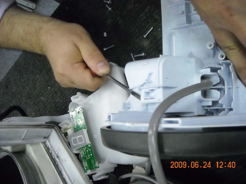
6 BOM List 1 Hepa filter frame 23 No bag safety device 2 Cord winder 24 Cover left 3 S-bag 25 Cover right 4 Suspension ring 26 Side frame right 5 Motor 27 Side frame left 6 Bellow 28 Lever CW arm 7 Suspension block 29 Connection 8 Motor cover 30 Rear cover 9 Front lid 31 Base 10 Rear wheel 32 Dust bag holder 12 Front wheel 33 Spring buttons 13 Front wheel support 34 Shaft button hinge 14 Air channel 35 Fixation cord winder 15 Shield 36 Filter lid cover 16 PCB control 37 Filter lid Front cover Sealing dust compartment Absorber motor cover Absorber motor cover towards HEPA filter Disaster filter Motor absorber Absorber filter lid 2 Absorber filter lid 1 Catch PCB pressure switches Lever ON/OFF Spring ON/OFF lever arm Handle Button filter lid right PIN for handle 2 ACCESSIBILITY The following chapter follows a disassembling process that step by step will allow the Technician to completely dismount the vacuum cleaner. Tags have been added to help finding quickly the needed item to be removed quickly. The following sections are outlined: - Dust bag cover and compartment - Display cover - PCB Display/Switch - Top cover - Housing - Cord winder - Handle - Wheels - Power module and power supply unit - Motor - HBTN ATTENTION: Boards and electronic devices could be damaged by electrostatic discharges. Don t touch any components without any ESD protection. 6

7 2.1 Dust bag cover Dust bag cover is easily removable. Open the cover, and press the locks on both sides with a screw driver. After that, pull the cover upwards. 7

8 2.2 Display cover You can remove the display cover with a normal screw driver. Pry the cover at the middle of the front side, and you can take it out easily. 8

9 2.3 PCB Display/Switch The display/switch PCB is fixed by clips on both sides. 9


10 2.4 Top cover Take out the screws, which you can see on the pictures below! Remove the sealing of dust compartment too! Remove the exhaust filter lid, and the filter! Open the lid, and bend it, while it s fall down! After that, you can remove the top cover with a simple movement. Press the appliance down, take the top cover by the handle, and pull it down! 10


11 2.5 Housing Take out the four screws from the dust compartment. Remove the side frames from both sides, and take out the screws, you can find below the frames On the left side, you can find two screws on the top, behind the parking slot. 11


12 After you take out the screws, you can remove the side panels. Remove the two screws, which takes place below the exhaust grill, and the other, you can find on the left side of the motor house. Turn over the cleaner, and lift the lower part up. 12

13 2.6 Cord winder After you removed the side panel from the right side, you can take out the cord winder easily. You have to disconnect the wires and the cooling hose, before you lift the cord winder out! After you lift up the cord winder you have to remove the cover from the back side, in order to the wall-plug can be removable. 13
14 14

15 2.7 Handle To take out the handle, you have to remove the two screws from the lower side of the top cover! 15


16 2.8 Power module and power supply unit You can find the power supply PCB below the left side panel. This PCB is fixed by clips, it is easily removable. The power module PCB takes place on the top of the cleaner, below the top cover. You can also find a pressure switch on the back side of the cleaner, left side of the exhaust filter. 16

17 2.9 Motor Take out the four screws, you can find between the motor house and the body of the appliance! After that, pull out the motor house from the body of the appliance! 17

18 3. Levels of Electronic Control 3.1 Display Layout for level 1 model, slider control: Basic software functionality - ON/OFF switch - Soft-start, function according to chapter Softstart and motor power change. - Automatic 50/60Hz detection. - Motor power regulated by slider Motor power regulation and LED-functionality 1. Main plug connected: -Motor shall be off Software calibration process of the slider potentiometer Calibration process of the potentiometer, to calibrate min power position: Erase the micro controllers actual calibrated value:. Disconnect the potentiometer from the control PCB.. Connect the main plug while keeping the On/Off button pressed.. Erase completed is indicated by oscillating the motor power. 18

19 . Disconnect the main plug. Calibrate potentiometer to microcontroller:. Make sure that the slider is adjusted to minimum power position.. Connect the main plug.. Calibrated value is now stored in the micro controllers memory and the cleaner can be operated as normal. 3.2 Display Layout for level 2 model, with LED display and step control: Basic software functionality -ON/OFF switch -Soft-start -Automatic 50/60Hz detection. -When started from unplugged, cleaner starts in power level 3, otherwise in last used mode. -5 manual power steps. -(+) increases power level up to power level 5. -(-) decreases power level down to power level 1. -Power indication by segment LED, S-bag and Filter status are indicated by two LED:s. -Failure indication Motor power regulation and LED-functionality 1. Main plug connected: - Motor is off. - Segment LED:s indicates standby indicating 0 2. First start by the On/Off switch (after main plug is connected): - Motor power starts, power level 3. - Segment LED indicates actual power. 3. (+) button is pressed: - Power steps up. - Segment LED indicates actual power. 4. (+) button is pressed, and kept pressed: - Power steps up automatically until power level 5 is reached. - Segment LED indicates actual power. 19
20 5. (-) button is pressed: - Power steps down. - Segment LED indicates actual power. 6. (-) button is pressed, and kept pressed: - Power steps down automatically until power level 1 is reached. - Segment LED indicates actual power. 7. Cleaner is turned off: - Actual power setting is remembered by that microcontroller. - Motor turns off. - Segment LED shows standby by indicating 0 8. Cleaner is turned on after being in standby mode: - Cleaner turns on and goes into last power setting used. 3.3 Display Layout for models with passive remote system: Basic Software functionality -Double ON/OFF switches, remote and body -Soft-start -Automatic 50/60Hz detection. -When started from unplugged, cleaner starts in power level 3, otherwise in last used mode. -5 manual power steps. -(+) increases power level up to power level 5. -(-) decreases power level down to power level 1. -Power indication by segment LED, S-bag and Filter status are indicated by two LED s. -Failure indication Motor power regulation and LED-functionality 1. Main plug connected: - Motor is off. - Segment LED s indicates standby indicating 0 2. First start by either of the two On/Off switches (after main plug is connected): - Motor power starts, power level 3. 20

21 - Segment LED indicates actual power. 3. (+) button is pressed: - Power steps up. - Segment LED indicates actual power. 4. (-) button is pressed: - Power steps down. - Segment LED indicates actual power. 5. Cleaner is turned off: - Actual power setting is remembered by that microcontroller. - Motor turns off. - Segment LED shows standby by indicating 0 6. Cleaner is turned on after being in standby mode: - Cleaner turns on and goes into last power setting used. 3.4 Display Layout for models with active remote system: Basic Software functionality -Double ON/OFF switches, remote and body -Soft-start -Automatic 50/60Hz detection. -When started from unplugged, cleaner starts in power level 3, otherwise in last used mode. -5 manual power steps. -(+) increases power level up to power level 5. -(-) decreases power level down to power level 1. -Power indication by segment LED, S-bag and Filter status are indicated by two LED's. -Failure indication. 21
22 3.4.2 Motor power regulation and LED-functionality 1. Main plug connected: - Motor is off. - Segment LED's indicates standby indicating 0 2. First start by either of the two On/Off switches (after main plug is connected): - Motor power starts, power level 3. - Segment LED indicates actual power. 3. (+) button is pressed: - Power steps up. - Segment LED indicates actual power. 4. (+) button is pressed, and kept pressed: - Power steps up automatically until power level 5 is reached. - Segment LED indicates actual power. 5. (-) button is pressed: - Power steps down. - Segment LED indicates actual power. 6. (-) button is pressed, and kept pressed: - Power steps down automatically until power level 1 is reached. - Segment LED indicates actual power. 7. Cleaner is turned off: - Actual power setting is remembered by that microcontroller. - Motor turns off. - Segment LED shows standby by indicating 0 8. Cleaner is turned on after being in standby mode: - Cleaner turns on and goes into last power setting used Brush motor functionality It is not possible to start the brush motor when the vacuum cleaner motor is turned off. If the cleaner is turned off by one of the On/Off switches, the brush motor also turns off. If the cleaner are turned off by one of the On/Off switches, the brush motor status is saved by the microcontroller, and when started again it reloads the status of the brush motor (on or off). 22
 turns on the cleaner into AUTO mode turns on the cleaner into manual mode and toggles the manual 5 power steps For vacuum cleaners without AUTO mode function: 1 turns on or off the cleaner 2")
23 3.5 Nozzle power supply interface For vacuum cleaners with AUTO mode function: button 1 button 2 button 3 button 4 turns on or off the cleaner turns on or off the nozzle motor (handled by the Aeropro PCB) turns on the cleaner into AUTO mode turns on the cleaner into manual mode and toggles the manual 5 power steps For vacuum cleaners without AUTO mode function: 1 turns on or off the cleaner 2 turns on or off the nozzle motor (handled by the PCB) 3 increases the cleaner power in up to 5 power steps 4 decreases the cleaner power in up to 5 power steps 23

24 3.6 Brush nozzle PCB 230V/110V active remote The remote control for the 230V/110V active system are a two wire connected PCB assembled in the cleaners bent end. From the remote control it is possible to control the cleaner functions. Note: PCB working with live voltage 230/110V. 3.7 Standby indication (for both RF and active versions) When the main is connected, and the cleaner is in standby mode. This is indicated by 0 on the LED display. 3.8 Reprogramming RF remote controller - Press ON/OFF button on cleaner and keep it pressed while inserting the main plug. - Keep the ON/OFF button pressed until the segment display LED indicates C, the cleaner is now in RF learning mode. Release the ON/OFF button. - On the remote control press the ON/OFF button. - If the cleaner have received the new RF remote address the segment LED will first indicate L, learning, and after that F, programming its memory. After successful learning process the display will show 0 - Start the cleaner either with the remote control or on the cleaner. 3.9 PCB's View of Level 1 control PCB ATTENTION: Boards and electronic devices could be damaged by electrostatic discharges. Don t touch any components without any ESD protection. 24

25 3.10Display PCB (level 2 4, segment LED display) 1 (-) button, level 2 2 (+) button, level 2 3 Segment LED 4 Connector pressure switch PCB 5 Connector On/Off PCB 6 Connector Active PCB, Level 4 7 Connector Power Module 8 Filter LED 9 S-bag LED ATTENTION: Boards and electronic devices could be damaged by electrostatic discharges. Don t touch any components without any ESD protection. 25

26 3.11Pressure switch PCB The pressure switch PCB contains the 2 pressure switches detecting clogged filter or S-bag. For level 3, RF version, also the RF receiver PCB and the RF antenna is assembled on this PCB. ATTENTION: Boards and electronic devices could be damaged by electrostatic discharges. Don t touch any components without any ESD protection. 26
27 4. PCB Power Module used for level 2-4 (position 014A) 4.1 Introduction Power module is intended as a module PCB for mainly vacuum cleaners from Electrolux Floor Care & Small Appliances AB. The module is intended to consist of a Triac, triggering a motor, and a power supply for additional connected electronic. 1 Power Module PCB. 2 Connector main voltage 3 Alternative main power connector / main power out 4 Motor connector 5 Connector to control PCB All different kinds of Power modules have the same configuration of connector configuration, simplifying design, service and cross over. 4.2 Connection for control unit To be able to control the power module a control unit is connected to the 5-pol connector, which also power supplies the control unit with 5VDC. The configuration for the connector is following: 1 Ground. 2 5VDC, maximum current according to level of power module. 3 Zero cross signal, square wave that follows the main frequency (5V amplitude). 4 Reserved for TCO signal (temperature control signal). Not implemented on the PCB, only reserved for the function. 5 Triac ignition signal from the control unit to the power module. 4.3 Low Current Power Module The low current power module contains a capacitive power supply. The low current power module can always be replaced by a high current power module, or International power module (see parts lists) Power supply design low current power module The 5V power supply is of the type capacitive supply. 27
28 4.3.2 Electrical specification Input voltage: 230V / 50Hz. Output voltage: 5V Max output current: 35mA@4,8V. NOTE: Output voltage is not insulated from main voltage 4.4 High Current Power Module The high current power module consists of a switched power supply for providing the logical voltage with higher current output Electrical specification switched power supply Input voltage: V / 50-60Hz. Output voltage: 5V ±5% Max output current: 220mA. 28

29 5. RF transmitter 5.1 Introduction The RF transmitter is used as remote control for a vacuum cleaner powered by a 3V changeable lithium cell. The transmitter uses the 433MHz band for transmitting data inside EU. With the transmitter it is possible to turn the appliance on and off, and regulate the motor power. Estimated lifetime for the battery in normal use is approximately 8-12 months. 5.2 Design Mechanical design, PCB shape SW1 ON/OFF SW2 (-) SW3 (+) 5.3 LED indication The assembled LED is intended to communicate the battery status to the user. When there is no LED indication it is time for the user to change the battery. In normal condition (standby) the LED are inactivated. If a button is pressed the LED activates for approximately 250 milliseconds. 6. PCB 230V/110V motor 6.1 Introduction PCB 230V is a new PCB to support the drive of a 230VAC motor mounted in the nozzle. The motors continuously current consumption is maximum 1A. The PCB can also be used without nozzle motor, and then only support a wired remote control between the cleaners bent end and the cleaners control unit. 6.2 PCB variants The 230V variant use single sided PCB. Low voltage variant (100V for USA, Japan) use double sided PCB together with UL approved coating. 6.3 Electrical overview 29

30 Sketch: Functional description The PCB is supplied with main voltage, dimensioned to be used with both 230V and 100V main power. A capacitive power supply is used to supply the electronics with 5VDC. The motor speed and motor status in the nozzle are controlled by a triac. The triac are controlled by the cleaners control unit. 6.4 Description Remote control signal and handling The remote control is connected to connector on the PCB. The remote control uses a two wire connection to the PCB, and is connected as following: - KEY +5V analog signal. - M2 GND. Note: live voltage potential. The controller on the PCB reads the analog signal level, and converts the signal to a frequency output signal, which is communicated to the control PCB. 30
31 6.5 Motor output The on/off of the motor nozzle is controlled by a Triac. The motor is also connected as follows - M1 motor phase - M2 motor neutral (shared with the GND for the remote control) Nozzle motor status is following: Plug in: OFF Switch cleaner on: OFF or last status. Switch cleaner off: OFF (+) or (-): No change Nozzle on/off: If nozzle motor is off and cleaner motor running turn it on Nozzle on/off: If nozzle motor is on and cleaner motor running turn it off Cleaner motor is off: Always off. 7. INDICATION & DIAGNOSTICS 7.1 Filter and S-bag indicators Activation The indicators are operated by the controller. If the pressure switches activates, this is indicated by the indicator LED s. After 2 seconds activation the corresponding LED will light up for 1 second, and after additional 57 seconds the corresponding LED will start to indicate continuously. During this time delay the pressure switch must not be deactivated. If it is deactivated, there will be a new 60 second delay when activated next time. The LED's will continue to indicate after the cleaner is turned off and in standby mode. At first start, after the main plug is connected, the S-BAG and FILTER indicator will turn on for one second, indicating that the LED is working. 31
32 7.1.2 Deactivation To deactivate the LED indicator after activation this can be made in three ways. First is to disconnect and reconnect the main connector. Also this can be made by turning off the cleaner, turn it on again and keep the on/off button pressed for 5 seconds. At last when turned on after being activated, and running without the actual pressure switch is activated for 30 seconds. 7.2 Error indication Level 1, potentiometer is not connected If the potentiometer is not connected, the controller starts oscillating the motor power when the main plug is connected to the mains Level 2-4, error indication and function Error (high prio) The highest levels will shutdown the motor and error codes that will be displayed are; E + 1 = motor error (disconnected/thermal) (Not in use) E + 2 = active failure E + 3 = active failure E + 4 = Flash error RF self learning (problem with erase or programming & enter self program. Mode) Error (low prio) Lowest error levels will indicate on display the error and the power could be reduced depending on type of application. Error codes that will be displayed are: E + 5 = P1 (pressure switch shorted during standby mode), power range 0-100%, no update of power level on display. E + 6 = P2 (pressure switch shorted during standby mode), power range 0-100%, no update of power level on display. E + 7 = RF-receiver (not working/not on board: no white noise), power range 0-75%, no update of power level on display Error Summary Peripheral status Display Main motor LED Filter LED Bag P1 Deactivated Start Up 0 0% Not Lit Not Lit (Filter) Standby 0 0% Not Lit Not Lit Running %-100% Not Lit Not Lit P1 Activated Start Up E + 5 0% Lit Not Lit (Filter) Standby 0 0% Lit Not Lit Running %-100% Lit(3s/60s) Not Lit P2 Deactivated Start Up 0 0% Not Lit Not Lit (Bag) Standby 0 Not Lit Not Lit Running %-100% Not Lit Not Lit P2 Activated Start Up E + 6 0% Not Lit Lit (Bag) Standby 0 0% Not Lit Lit Running %-100% Not Lit Lit(3s/60s) Active Start Up 0 0% disconnected Standby 0 0% 32
33 Running E + 2 0% after<1sec Active Start Up 0 0% No frequency Standby 0 0% Running E + 3 0% after 3sec 33
34 8 TROUBLE SHOOTING Problem Checks Cleaner without remote: -Investigate if the plastic knob reaches the ON/OFF switch on the PCB. -Replace the control unit (display PCB) -Check connection to the ON/OFF switch board Cleaner with radio remote: -Investigate if both ON/OFF (cleaner and remote) is not working. If remote ON/OFF working, but not cleaner ON/OFF: -Investigate if the plastic knob reaches the ON/OFF switch on the PCB. -Replace the control unit (display PCB). If cleaner ON/OFF working, but not remote ON/OFF: - Investigate if the LED on the remote indicates transmission. If not, change battery and try again. -If still no LED indication on remote, change remote control and reprogram the cleaner according to above instruction. -If LED indicates transmission, try replacing the remote according to above instruction. If cleaner starts, replace the RF remote control. -If still no function, replace the control unit in the cleaner. Be aware of the position of the radio antenna. If replacing the control unit this has to learn the RF-remote address according to above description. If no reaction on any ON/OFF buttons: replace the control unit (display PCB). Cleaner doesn t start; if standby is indicated on display Cleaner with active motor nozzle: -Investigate if both ON/OFF (cleaner and remote) are not working. If remote ON/OFF working, but not cleaner ON/OFF: - Investigate if the plastic knob reaches the ON/OFF switch on the PCB. -Replace the control unit (display PCB). If cleaner ON/OFF working, but not remote ON/OFF: -Check the bent end, test with another HBTN. If the cleaner starts, change. -Check wiring from hose connection to 2G active PCB. -Change 2G active PCB, test. -Check wiring between 2G active PCB and control unit for failure or bad connection. -Change the control unit. If no reaction on any ON/OFF buttons: replace the control unit (display PCB). Cleaner doesn t start; no indication on display -Check if the Power module PCB gets main voltage. -Check communication wire between Power module and control unit for failure or bad connection. -Change the control unit. -Change the Power module. -Check wire connection from CW. Cleaner doesn t start; display shows normal running mode -Check motor voltage, if no voltage, check the electronics as below, else check motor TCO and motor. -Check communication wire between Power module and control unit for failure or bad connection. -Change the control unit. -Change the Power module. Not possible to change power level Cleaner without remote: Investigate if the plastic knob reaches the +/- switches on the PCB. Replace the control unit (display PCB). 34
35 Cleaner with radio remote: -Investigate if the LED on the remote indicates transmission. If not, change battery and try again. -If still no LED indication on remote, change remote control and reprogram the cleaner according to above instruction. -If LED indicates transmission, try replacing the remote according to above instruction. If cleaner starts, replace the RF remote control. -If still no function, replace the control unit in the cleaner. Be aware of the position of the radio antenna. If replacing the control unit this has to learn the RF-remote address according to above description. Cleaner with active motor nozzle: -Check the bent end, test with another HBTN. If possible to change power setting, change. -Check wiring from hose connection to 2G active PCB. -Change 2G active PCB, test. -Check wiring between 2G active PCB and control unit for failure or bad connection. -Change the control unit. If the power regulation works for the first minutes after start, and then stops working. Motor seems to run only in maximum speed. -Check the cooling system to the Power module (tube, cooling house, tube connection to dust compartment). -Change the Power module PCB. Filter or S-bag indicator always or never indicates Nozzle motor doesn t start or stop on active system -Check the bag or filter if replacement is needed. -Check the tubes and communication wire to the pressure switches on the control unit PCB (display). - Change the control unit PCB (display). -Check the bent end, test with another HBTN. If possible to start nozzle motor, change. -Check wiring from hose connection to 2G active PCB. -Change 2G active PCB, test. -Check wiring between 2G active PCB and control unit for failure or bad connection. -Change the control unit. LED:s on nozzle doesn t light, but nozzle motor is running -Change nozzle electronic 35
SERVICE MANUAL VACUUM CLEANER ULTRA ACTIVE. Number of publication. E.H.P. Floor Care. Factory: XX - XXXXXX (YY) Edition: Date
 Edition: Date") SERVICE MANUAL VACUUM CLEANER E.H.P. Floor Care Number of publication Nr EN ULTRA ACTIVE Factory: XX - XXXXXX (YY) Edition: Date EN Publication number Nr Rev. xx Month/year PR - 1/37 1 TABLE OF CONTENTS
SERVICE MANUAL VACUUM CLEANER E.H.P. Floor Care Number of publication Nr EN ULTRA ACTIVE Factory: XX - XXXXXX (YY) Edition: Date EN Publication number Nr Rev. xx Month/year PR - 1/37 1 TABLE OF CONTENTS
TABLE OF CONTENTS. DESCRIPTION Motors, on/off switches, wires and PCBs A Cable sets A Body and body parts A
 05-12 TABLE OF CONTENTS A 5.6.3 1 DESCRIPTION PLAN Motors, on/off switches, wires and PCBs A - 5.6.3-2 Cable sets A - 5.6.3-4 Body and body parts A - 5.6.3-6 Dust bags and filters A - 5.6.3-8 Hoses, connections
Removal and Installation8
 8 Screw Types 8-4 Top Cover Assembly 8-5 Left Hand Cover 8-6 Right Hand Cover 8-10 Front Panel Assembly 8-14 Left Rear Cover 8-15 Right Rear Cover 8-16 Extension Cover (60" Model only) 8-17 Media Lever
GD 5, GD 10, GD 5 Battery
 Model: GD 10 BACK GD 5 BACK Part List US-English Table of Contents Motor and motor parts 3 Electrical parts 5 Container parts 7 Straps parts 9 Filters 11 Nozzles 32 mm 13 Tubes, hose 32 mm 15 Overview
Installation Instructions
 Installation Instructions This document provides information on: important pre-installation considerations power supply requirements initial handling procedures installing the module using the indicators
Installing System Board Options
 CHAPTER 8 Installing System Board Options This section describes how to install the following options: Expansion cards Memory modules Microprocessor This section also includes instructions for replacing
Ref. No. Part Name & Description Part No. Quantity Remarks
 - R _ Ref. No. Part Name & Description Part No. Quantity Remarks A -1 Nozzle Housing AC01ABCCZGU4 1 Includes A-26 Packing A - 2 Window AC21HAFV200 1 A - 3 Shaft (Plastic) AMC25S-V00 1 A - 4 Furniture Guard
DRC200Z 18V x 2 (36V) ROBTIC CLEANER
 ROBTIC CLEANER") 06-2016 DRC200Z 18V x 2 (36V) ROBTIC CLEANER 9 5 11 6 4 10 12 A07 A08 7 A03 A04 13 40 66 15 41 44 16 51 63 14 75 29 89 31 67 70 71 54 88 73 45 35 74 92 33 68 69 72 53 43 42 39 26 25 32 27 90 91 17 52 61
06-2016 DRC200Z 18V x 2 (36V) ROBTIC CLEANER 9 5 11 6 4 10 12 A07 A08 7 A03 A04 13 40 66 15 41 44 16 51 63 14 75 29 89 31 67 70 71 54 88 73 45 35 74 92 33 68 69 72 53 43 42 39 26 25 32 27 90 91 17 52 61
LCC1653/01, LRI1653/01 ActiLume DALI System
 1/8 Product description The Philips ActiLume lighting control system consists of a small, lightweight sensor and controller, designed for easy integration into luminaires. ActiLume is a true Plug and Play
FT-20 Fire Training Fog Machine User Manual English
 FT-20 Fire Training Fog Machine User Manual English 2017 Antari Lighting and Effects Ltd. 1 User Manual - English Safety Information Please read the following safety information carefully before operating
Instruction Manual. M Pump Motor Controller. For file reference, please record the following data:
 Instruction Manual M Pump Motor Controller For file reference, please record the following data: Model No: Serial No: Installation Date: Installation Location: When ordering replacement parts for your
Installation Instructions
 Installation Instructions This document provides information on: important pre-installation considerations power supply requirements initial handling procedures installing the module using the indicators
Installation Instructions
 Installation Instructions This document provides information on: important pre-installation considerations power supply requirements initial handling installing the module using the indicators for troubleshooting
To connect the AC adapter:
 Replacing the AC Adapter Replacing the AC Adapter 3 Plug the power cord into a wall outlet. The power indicator turns on. To connect the AC adapter: Connect the power cord to the AC adapter. Power indicator
Thermometer / Barometer System
 TBX USER S MANUAL Thermometer / Barometer System 616TA Pg.2of12 TABLE OF CONTENTS QUICK START GUIDE... 3 INTRODUCTION... 6 SPECIFICATIONS... 6 TERMINAL COMPARTMENT LAYOUT... 7 FEATURES... 8 OPERATION...
Electronic Service Manuals
 Electronic Service Manuals This electronic document is provided as a service to our customers. We do not create the contents of the information contained in this document. Should you have detailed questions
Trouble Shooting Leveling Control Box Electric Jacks. Touch Pad LED Probable Cause Solution
 Trouble Shooting Leveling Control Box 140-1224 Electric Jacks Copyright Power Gear Issued: January 2013 #82-L0524, Rev. OA Touch Pad LED Probable Cause Solution 1. On/Off LED will not light 2. Wait LED
Instructions for SVC-KIT-0020
 Kaleidescape, Inc. July 22, 2010 Instructions for SVC-KIT-0020 Title Time to complete 1U Server Power Supply Replacement 1 hour Procedure to complete Locate Parts and Tools Service Kit Parts Power supply
Motorized Flat Panel TV Lift
 Mounting Instructions Item No.: 421.68.443 & 421.68.444 Motorized Flat Panel TV Lift Content 1. Important safety instructions. 2. Specifications and main dimensions. 3. Parts included. 4. Installation.
W205-N RVC NTV-KIT703
 3950 NW 120 th Ave, Coral Springs, FL 33065 TEL 561-955-9770 FAX 561-955-9760 www.nav-tv.com info@nav-tv.com W205-N RVC NTV-KIT703 Overview The W205-N RVC Kit interfaces a backup camera input (with active
INSTALLATION INSTRUCTIONS
 TS1000C TS700C INSTALLATION INSTRUCTIONS CONTENT: 1. Important safety instructions. 2. Specifications and main dimensions. 3. Parts included. 4. Installation. 5. RF remote system. 6. Feature functions
asense m III in industrial wall mounted housing / CO sensor with built-in general purpose controller
 Manual for Installation CO 2 asense m III in industrial wall mounted housing / CO sensor with built-in general purpose controller 9 10 2 1 6 10 8 3 4 5 7 Fig. 1 1 Wall plate 2 PCB (Factory supplied mounted
FT-20 Fire Training Fog Machine User Manual English
 FT-20 Fire Training Fog Machine User Manual English 2018 Antari Lighting and Effects Ltd. 1 User Manual - English Safety Information Please read the following safety information carefully before operating
DLA. DMX512 Analyzer. DLA Users Manual SV2_00 B.lwp copyright ELM Video Technology, Inc.
 DLA DMX512 Analyzer DLA DLA-HH 1 Table Of Contents IMPORTANT SAFEGUARDS... 2 DLA OVERVIEW... 3 CONNECTION... 3 OPERATION... 3 HARDWARE SETUP... 4 DLA-HH (PORTABLE) LAYOUT... 4 CHASSIS LAYOUT... 4 DLA MENU
Instruction book IQAN-LSL. Publ no HY /UK Edition 0301
 Instruction book IQAN-LSL Publ no HY17-8367/UK Edition 0301 Contents 1 Introduction......................................................2 2 Precautions.......................................................3
Installation manual CF8-W-Disp-AL
 Installation manual CF8-W-Disp-AL CO 2 transmitter with two relays mounted in industrial housing prepared for Modbus communication protocol 4 7 8 8 6 3 2 5 Wall plate 5 Snap-in lid 2 PCB (Factory supplied
CDD Carbon Dioxide Transmitter
 Introduction The OSA CO2 transmitter uses Infrared Technology to monitor CO2 levels within a range of 0 2000 ppm and outputs a linear 4-20 ma or 0-5/0-10 Vdc signal. The enclosure is designed to operate
Service & Maintenance
 Service & Maintenance Internal Amplifier External (Peavey) Amplifier Core & HDD Monitor UPS Dollar Bill Acceptor Coin Mechanism Cleaning Fans & Filter G1-1 Internal Amplifier Amplifier Removal 1. Disconnect
Installation Manual. 65 Interactive LED/LCD. Model: HILF65101 (64.56 )
") Installation Manual 65 (64.56 ) Model: HILF65101 65 Interactive LED/LCD QUICK SETUP GUIDE For further information, see the user manual. Please contact directly if you have questions on the use of the touch
Installation Manual 65 (64.56 ) Model: HILF65101 65 Interactive LED/LCD QUICK SETUP GUIDE For further information, see the user manual. Please contact directly if you have questions on the use of the touch
DRC200Z 18V x 2 (36V) ROBTIC CLEANER
 ROBTIC CLEANER") 06-2016 DRC200Z 18V x 2 (36V) ROBTIC CLEANER 9 5 11 6 4 10 12 A07 A08 7 A03 A04 13 40 66 15 41 44 16 51 63 14 75 29 89 31 67 70 71 54 88 73 45 35 74 92 33 68 69 72 53 43 42 39 26 25 32 27 90 91 17 52 61
06-2016 DRC200Z 18V x 2 (36V) ROBTIC CLEANER 9 5 11 6 4 10 12 A07 A08 7 A03 A04 13 40 66 15 41 44 16 51 63 14 75 29 89 31 67 70 71 54 88 73 45 35 74 92 33 68 69 72 53 43 42 39 26 25 32 27 90 91 17 52 61
CDD4 Series Room CO2 Transmitter Installation Instructions
 CDD4 Series Room CO2 Transmitter Installation Instructions Introduction The CO2 transmitter uses Infrared Technology to monitor CO2 levels and outputs a linear 4-20 ma or 0-5/0-10 Vdc signal. Options include
Instruction book IQAN-LST. Publ no HY /UK Edition 0301
 Instruction book IQAN-LST Publ no HY17-8364/UK Edition 0301 Contents 1 Introduction......................................................2 2 Precautions.......................................................3
Replacing the Power Supply
 APPENDIX B This appendix includes information on how to replace the power supply for the Cisco AS550XM universal gateway and contains the following sections: Safety Recommendations, page B-1 Required Tools
Please Read Instruction Carefully Before Installation! Figure 1: A/CO2-DUCT
 Installation and Operation Instructions A/CO2-DUCT Series Please Read Instruction Carefully Before Installation! Figure 1: A/CO2-DUCT PRECAUTIONS REMOVE POWER BEFORE WIRING. NEVER CONNECT OR DISCONNECT
Pro Series LED Controllers Part numbers: pro-4-in-1-receiver, dim-pro-knob-us-w dim-pro-knob-wa, dim-pro-knob-rgb, rgbw-pro-touch, rgb-pro-remote
 11235 West Bernardo Court, Suite 102 San Diego, CA 92127 888-880-1880 Fax: 707-281-0567 EnvironmentalLights.com Pro Series LED Controllers Part numbers: pro-4-in-1-receiver, dim-pro-knob-us-w dim-pro-knob-wa,
LH 700. Spare parts list. Forward and reversible plate. Valid from serial number. LH 700 Hatz Electric start 810 mm Bio
 LH 00 Spare parts list Forward and reversible plate LH 00 Hatz Electric start 0 mm LH 00 Hatz Electric start 0 mm Bio LH 00 Hatz Electric start 0 mm LH 00 Hatz Electric start 0 mm Bio Valid from serial
Magnum Club Smoke System
 AND INSTALLATION VERSION.0 Martin Professional A/S,Olof Palmes Allé 8, DK-800,Aarhus N Phone: +45 87 40 00 00 Internet: www.martin.dk Magnum Club Smoke System Fluids Suitable for this system: CONNECTIONS
TOSHIBA Potable Printer B-EP4DL SERIES. Maintenance Manual. Document No. EO Original Sep., 2008 (Revised ) PRINTED IN JAPAN
 PRINTED IN JAPAN") TOSHIBA Potable Printer B-EP4DL SERIES Maintenance Manual Original Sep., 2008 (Revised ) Document No. EO18-33023 PRINTED IN JAPAN WARNING! Follow all manual instructions. Failure to do so could create
TOSHIBA Potable Printer B-EP4DL SERIES Maintenance Manual Original Sep., 2008 (Revised ) Document No. EO18-33023 PRINTED IN JAPAN WARNING! Follow all manual instructions. Failure to do so could create
Allworx 24x Service and Troubleshooting Guide
 Allworx 24x Service and Troubleshooting Guide -PAGE INTENTIALLY LEFT BLANK- Table of Contents 1 Safety Instructions...1 1.1 Electrical...1 1.2 Electrostatic Discharge...1 2 Chassis Views...2 3 Exterior
Section. Service & Maintenance. - Core & Hard Disk Drive (HDD) - Amplifier - Monitor - UPS - Dollar Bill Acceptor - Fan Filter G - 1
 - Amplifier - Monitor - UPS - Dollar Bill Acceptor - Fan Filter G - 1") Section G Service & Maintenance - Core & Hard Disk Drive (HDD) - Amplifier - Monitor - UPS - Dollar Bill Acceptor - Fan Filter G - 1 Core Removal Core & HDD 1. Open the door. 2. Perform shutdown procedure.
Section G Service & Maintenance - Core & Hard Disk Drive (HDD) - Amplifier - Monitor - UPS - Dollar Bill Acceptor - Fan Filter G - 1 Core Removal Core & HDD 1. Open the door. 2. Perform shutdown procedure.
USER S MANUAL. DAS-G01 The Power of Tomorrow
 USER S MANUAL DAS-G01 The Power of Tomorrow Richmond Heights 2018 0 USER S MANUAL DAS-G01 The Power of Tomorrow Richmond Heights 2018 Page 1 USER'S MANUAL TABLE OF CONTENTS Page # 1.0 GENERAL INFORMATION...
Sierra Dual 24 Volt Brushless DC Motor Controller Product Specification. Assembly 025F0348
 Sierra Dual 24 Volt Brushless DC Motor Controller Product Specification Assembly Revision History ECN # Date Rev Description By EC77363 03/15/17 A Initial Release K. Jones EC81620 11/15/17 B Added Agency
LH 700. Spare parts list. Forward and reversible plate. Valid from serial number. LH 700 Hatz Electric start 810 mm Bio
 Forward and reversible plate Hatz Electric start 0 mm Hatz Electric start 0 mm Bio Hatz Electric start mm Bio Valid from serial number 0000 0000 0000 Contents Contents General information.....................................................................................................................................
Parts Manual Kleen Sweep 32R Rider Sweeper
 Parts Manual Kleen Sweep 32R Page 2 Table of Contents Side broom R.H., part 1... Side broom R.H., part 2... Front wheel drive... Accelerator... Steering... Seat group... Group of main sweeper roller, part
Installation Instructions
 Installation Instructions This document provides information on: important pre-installation considerations power supply requirements initial handling installing the module using the indicators for troubleshooting
The Eye Com 7000 Dual Page Reader Operating and Maintenance Instructions
 A MEDIA INDEPENDENT DOCUMENT MANAGEMENT COMPANY EYE COMMUNICATION SYSTEMS, INC. 455 E. Industrial Drive P.O. Box 620 Hartland, WI 53029 USA (262) 367-1360 or (800) 558-2153 Fax: (262) 367-1362 www.eyecom.com
How to assemble and disassemble Anafi
 How to assemble and disassemble Anafi Prerequisites The best way to repair ANAFI is to use Parrot official drones repair kit. You will need the cruciform as well as the Torx 5 (T5) in order to carry out
CODE 50108, 50110, 50164, 50165
 CODE 50108, 50110, 50164, 50165 ASSEMBLY PAGE NAME Machine Assembly Machine Assembly Machine Assembly (Wire feed chamber) Machine Assembly (Wire feed chamber) Feeding Unit Assembly CODE NO.: K NO.: FIGURE
AME 658 SU/ SD with safety function Motorized actuators for AB-QM valves
 AME 658 SU/ SD with safety function Motorized actuators for AB-QM valves Description Main data: 24V AC/DC powered actuators Control input signal: modulating or 3-point Selectable actuator speed Max. medium
Manual# Installation Manual. 200E Series. DCU 210E/208E Engine Panel RP 210E/220E Remote Panel
 Manual# 1006495 Installation Manual 200E Series DCU 210E/208E Engine Panel RP 210E/220E Remote Panel Installation Manual for the Marine Pro 200E Series ~~~ DCU 210E/208E Diesel Engine Control Unit RP 210E/220E
Megatouch FORCE Monitor Chassis Board Replacement
 Megatouch FORCE Monitor Chassis Board Replacement Visit the Merit Industries, Inc. Web site http://www.meritind.com merit industries, inc. PM0337-01 Rev C Table of Contents FORCE Classic Monitor Chassis
MINI MCR-SL-MUX-V8-FLK 16
 Multiplexer Data sheet 445_en_4 PHOENIX CONTACT 22-5-2 Description The MINI Analog multiplexer can be used to generate one analog output from up to eight input signals. During cyclical execution, 8, 6,
T7560A1036 Digital Wall Module
 T7560A1036 Digital Wall Module HONEYWELL EXCEL 5000 OPEN SYSTEM BEFORE INSTALLATION All wiring must comply with local electrical codes and ordinances or as specified on installation wiring diagrams. T7560A1036
Shack Clock kit. U3S Rev 2 PCB 1. Introduction
 Shack Clock kit U3S Rev 2 PCB 1. Introduction Thank you for purchasing the QRP Labs Shack Clock kit. This clock uses the Ultimate3S QRSS/WSPR kit hardware, but a different firmware version. It can be used
Navigation interface for Jeep GC 5 RA2 NTV-KIT581
 3950 NW 120 th Ave, Coral Springs, FL 33065 TEL 561-955-9770 FAX 561-955-9760 NNG-Jeep GC Navigation interface for Jeep GC 5 RA2 NTV-KIT581 NNG-JEEP GC Kit Content 5 1 6 4 7 2 3 1. 2. 3. 4. 5. 6. 7. 8.
Manual. LC-16 system. LC-16 Inkjet Printer 1
 Manual LC-16 system LC-16 Inkjet Printer 1 Index ENVIRONMENT. 3 OPERATOR S SAFETY 3 OPERATION SAFETY 3 PART 1 INSTALLATION AND PARAMETER SETTING 4 1) Preparing 4 2) Installation 4 3) Priming 4 4) Parameter
970 Serials Lights. Multi-Function Lights System FEATURES SPECIFICATION
 970 Serials Lights Multi-Function Lights System FEATURES Suitable for Marine & Vehicle Easy to install & Easily relearning Remote Unit Wide Range Rotation movement. Dual Function Control with Wire Control
Rhino Buffer Module PSM24-BFM600S. Operating Instructions
 Rhino Buffer Module PSM24-BFM600S Operating Instructions RHINO BUFFER MODULE PSM24-BFM600S Description The PSM24-BFM600S Buffer Module will hold the output voltage of a 24 VDC power supply after brownouts
Haze 800 DMX. User Guide. English
 Haze 800 DMX User Guide English Introduction Box Contents Haze 800 DMX Remote Control (wired) User Guide Safety & Warranty Manual Support For the latest information about this product (documentation, technical
SW-250 Wireless Control High Output Snow Machine User Manual
 SW-250 Wireless Control High Output Snow Machine User Manual English Français Deutsch 中文 2014 Antari Lighting and Effects Ltd. 1 2 ANTARI SW-250 SNOW MACHINE INTRODUCTION Thank you for choosing Antari
RPX Series USER S MANUAL
 RPX Series USER S MANUAL INDEX 1.1 Introduction page 1 1.2 Packing page 1 1.3 Drawing page 2~16 1.4 Features page 17 1.5 Specification page 18~21 1.6 Installation & Testing page 22~23 1.7 Hot-Swap Procedures
S-100X / S-200X Snow Machine User Manual
 S-100X / S-200X Snow Machine User Manual English Français Deutsch 中文 2014 Antari Lighting and Effects Ltd. 1 2 User Manual Antari S-100X & S-200X Snow Machine Introduction Thank you for choosing an ANTARI
Table of Contents. 1 Welcome. 2 Install your Access Point-I. 3 Using the Access Point-I
 Table of Contents 1 Welcome Introducing the Avaya Wireless LAN 1-1 About the Access Point-I 1-2 Finding Information 1-3 2 Install your Access Point-I Overview 2-1 Verify Kit Contents 2-2 Write Down Product
E401. User Manual. The New Vision of Touch
 E401 User Manual The New Vision of Touch E401 User Manual OVERVIEW This kit is designed for evaluation and development of QT401-based QSlide slider controls. It includes a fully assembled slider PCB, demo
2. BASE UNIT ASS'Y B06 B02 B01 B03 B04 B05
 2. BASE UNIT ASS'Y B06 B02 B01 B03 B04 B05 ASKO, WL6532XXL - Front loader #1076532PP (WL6532) Pos Spare part No. Description Qty Comment Base B01 52G043A110 Voltage Regulator 1 Pc's B02 3610392700 Base
Installation Instructions
 Installation Instructions Cat. No. 1771-OND Series B This document provides information on: important pre-installation considerations power supply requirements installing the module setting the fault mode
PARTS LIST
 2017.09.2 PARTS LIST TABLE OF CONTENTS Cabinet Push Clean & Basic & XC 1 Container ATTIX 30 4 Accessories 6 Filtersystem XC Filtersystem Push Clean & Basic 10 Motor Basic and Push Clean 12 Motor XC 14
Operational Manual Spectrophotometer Model: SP-830 PLUS Metertech Inc.
 Operational Manual Spectrophotometer Model: SP-830 PLUS Metertech Inc. Version 1.06 Metertech Inc. provides this publication as is without warranty of any kind, either express or implied, including, but
LFWLP350 SERIES 350 Watt Open Frame Power Supply Measures: 5.00 x 3.00 x 1.00
 Features 5 x 3 x 1 Inches Form factor 350 Watts with Forced Air Cooling & 200 Watts Convection Cooling Efficiencies upto 94% -40 to 70 degree operating temperature* 12V / 0.5A Fan Output, Thermal Shut-Down
SPK User Manual. 900MHz Wireless Stereo Headphones INTRODUCTION FEATURES IMPORTANT SAFETY INFORMATION
 INTRODUCTION Thank you for purchasing our 900Mhz compact cordless stereo headphone system that takes advantage of the very latest advances in wireless transmission technology so you SPK-9100 900MHz Wireless
2-Way Wireless I/O Expander Installation Guide
 2-Way Wireless I/O Expander Installation Guide For more detailed information please refer to the iconnect Installer Manual provided on our website: www.electronics-line.com Table of Contents 1. Introduction...
PC170 Control Box USER MANUAL 24V DC GEAR MOTOR FOR RESIDENTIAL
 PC170 Control Box 24V DC GEAR MOTOR FOR RESIDENTIAL USER MANUAL INDEX 1. CONTROL BOX 2. SETTING 2.1 SW1 DIP SWITCH SETTING 2.1.1 SLOWDOWN ADJUSTMENT (DIP 1. SLOW) 2.1.2 OVER-CURRENT ADJUSTMENT (DIP 2.OVER
Page Housing Plastic Metal Mounting DIN Rail or surface mount Panel or bracket mount Wattage Range 10W to 240W 7.5W to 240W 10W to 300W
 Selection Guide Selection Guide PS5R Slim Line PS5R PS3L Operator Interfaces Communication & Networking PLCs NEW Models Appearance Automation Software Page 107 113 118 Housing Plastic Metal Mounting DIN
INSTRUCTION MANUAL VOLTAGE REGULATOR MAXBEC2D PLUS EX
 VOLTAGE REGULATOR MAXBEC2D PLUS EX Released by JETI model s.r.o. 29. 10. 2014 CONTENT 1. INTRODUCTION... 3 2. DESCRIPTION... 4 2.1 MAXBEC2D PLUS... 4 2.2 MAGNETIC SWITCH... 4 2.3 RC SWITCH... 5 3. CIRCUITS...
Free Energy Band RCC30U Room Temperature Controller for Four-pipe Fan Coil Unit
 Document No. 155-324 Free Energy Band RCC30U Room Temperature Controller for Four-pipe Fan Coil Unit Description Features Application Product Number Room temperature controller for four-pipe fan coil units.
MFJ-484 GRANDMASTER MEMORY KEYER CONTROL FUNCTIONS
 MFJ-484 GRANDMASTER MEMORY KEYER The MFJ-484 is a highly sophisticated memory keyer using 15 state-of-the-art Integrated Circuits and 4 Random Access Memories which are standards of the industry. It provides
MC 11 EB-2 Power supply cabinet with external bus, AC version
 MC 11 EB-2 Power supply cabinet with external bus, AC version USER/MAINTENANCE MANUAL 1 SLOT 0 SLOT 1 SLOT 2 SLOT 3 SLOT 4 SLOT 5 SLOT 6 SLOT 7 SLOT 8 SLOT 9 SLOT 10 SLOT 11 EB-2 (a) MC11 (b) (c) Figures
Written By: Andrea Giannone
 How to Fix iphone 4S Wi-Fi Grayed Out Use this guide to permanently fix an "unclickable" grayed out Wi-Fi button in the iphone 4s. Written By: Andrea Giannone ifixit CC BY-NC-SA www.ifixit.com Page 1 of
What can the DD700 Do
 What can the DD700 Do RF signal detector for 100HZ to 3.5 GHz - Wireless CCTV (hidden camera) - Wireless Phone line tap detection - Laser taps detection and Laser tapping prevention using white noise generator.
impact INSTRUCTIONS LiteTrek 4.0 Monolight lighting equipment and accessories
 impact lighting equipment and accessories LiteTrek 4.0 Monolight INSTRUCTIONS Congratulations on your purchase of the Impact LiteTrek 4.0 Portable Monolight. Enjoy the many benefits of a portable strobe
Wireless Key fob, Key pad & Receiver Range
 Wireless Key fob, Key pad & Receiver Range 4Ch Wireless Receiver 4x Voltage Free relay outputs (NO + NC) 100m Transmission range Multiple user codes 2 Channel wireless control Clear hinge up lid 12V DC
INTRODUCTION CT87E FEATURES AND CONTROLS
 INTRODUCTION The CT87E is a precision instrument used to monitor and record the presence or absence of voltage, light, or sound level such as what would be produced by an operating electric motor or compressor.
Installation Instructions
 Installation Instructions This document provides information on: important pre-installation considerations power supply requirements initial handling installing the module short circuit protection using
XPS 15 2-in-1. Service Manual. Computer Model: XPS Regulatory Model: P73F Regulatory Type: P73F001
 XPS 15 2-in-1 Service Manual Computer Model: XPS 15-9575 Regulatory Model: P73F Regulatory Type: P73F001 Notes, cautions, and warnings NOTE: A NOTE indicates important information that helps you make better
MiR Bluetooth Box. Technical Documentation
 MiR Bluetooth Box Technical Documentation Version 1.2 Software release 1.5 Release date: 11.04.2016 Table of contents 1 Introduktion...3 1.1 Feedback signal...3 1.2 Indication of relays states...3 2 Dimensions...3
LED55WPG Programmable LED Driver
 Dimmable Constant Current Rev 8-9-7 Electrical Specifications Input Voltage Range: Frequency: Power Factor: Inrush Current: Input Current (Max): -77 Vac Nom. (8-35 V Min/Max) 5/6 Hz Nom. (47-63 Hz Min/Max)
Model HM-535 Power Supply Installation and Service Instructions
 Model HM-535 Power Supply Installation and Service Instructions 430-535 0104 2004 Heritage MedCall, Inc SENTRY INSTALLATION & SERVICE INSTRUCTIONS POWER SUPPLY UNIT Model HM-535 IMPORTANT SAFETY INSTRUCTIONS
Line Interactive 1000VA/1400VA/2000VA Uninterruptible Power System
 USER MANUAL Line Interactive 1000VA/1400VA/2000VA Uninterruptible Power System 614-06762-00 IMPORTANT SAFETY INSTRUCTIONS SAVE THESE INSTRUCTIONS This manual contains important instructions for Line Interactive
REMOVE COVERS. 1. Remove three screws from the Side Panel (L). 2. Slide the Side Panel (L) backward, and raise it to remove from the printer.
. 2. Slide the Side Panel (L) backward, and raise it to remove from the printer.") REMOVE COVERS 1. Remove three screws from the Side Panel (L). 2. Slide the Side Panel (L) backward, and raise it to remove from the printer. 3. Fully open the Top Cover. 4. Release the tab on the right
REMOVE COVERS 1. Remove three screws from the Side Panel (L). 2. Slide the Side Panel (L) backward, and raise it to remove from the printer. 3. Fully open the Top Cover. 4. Release the tab on the right
Ag Leader Technology Insight. Direct Command Installation Spra-Coupe 7000 Series
 Note: Indented items indicate parts included in an assembly listed above. Part Name / Description Part Number Quantity Direct Command Spra-Coupe 7000 Kit 4100531 1 Liquid Product Control Module 4000394
TR2 1000W. User's Manual >> ATX12V 2.2 & EPS 12V 2.91 Version. ATX 12V 2.2 & EPS 12V 2.91 Version. Thermaltake TR2 Power Supply
 TR2 000W ATX V 2.2 & EPS V 2.9 Version User's Manual >> Thermaltake TR2 000W Power Supply www.thermaltake.com Thermaltake TR2 thermaltake@thermaltake.com Power Supply www.tr2tt.com sales.tr@tr2tt.com Table
S-500 Snow Machine User Manual English
 S-500 Snow Machine User Manual English 2016 Antari Lighting and Effects Ltd. 2 User Manual Safety Information Please read the following safety information carefully before operating the machine. Information
jcmtechnologies GSM-CARD/VGSM-CARD user s manual communications card
 jcmtechnologies user s manual GSM-CARD/VGSM-CARD communications card EN Contents Safety instructions 3 Introduction 4 General description 4 Introduction 6 Assembly 6 Configuration 7 Verification 8 LED
Dell Inspiron N5110 Service Manual
 Dell Inspiron N5110 Service Manual Regulatory model: P17F Regulatory type: P17F001 Notes, Cautions, and Warnings NOTE: A NOTE indicates important information that helps you make better use of your computer.
the TS-520 Noise Blanker board to and making wiring changes to your SB-303 receiver!!!!
 The Kenwood TS-520 s Noise Blanker board, ID# X54-1080-10, can be installed in a Heathkit SB-303 receiver quite easily. The Noise Blanker board operates directly off of the SB-303 s 15VDC supply. Therefore,
Manual 04 - Logic Board
 Manual 04 - Logic Board Written By: Josh Patterson 2017 guides.cellphonesandbox.com Page 1 of 16 TOOLS: Technician Starter Package (1) 2017 guides.cellphonesandbox.com Page 2 of 16 Step 1 Removal 1 - Battery
Operating Instructions KEYPAD. Compatible WIRELESS ACCESS CONTROL
 Operating Instructions KEYPAD Compatible WIRELESS ACCESS CONTROL Contents Technical specifications page 1 Approvals page 1 Changing the Master code page 2 Adding a User code page 3 Deleting a User code
Electrical Specifications VAC/390 VDC, Universal (Derate from 100% at 100V AC to 90% at 90V AC)
") WLP350 Industrial Features 5 x 3 x 1 Inches Form factor 350 Watts with Forced Air Cooling & 200 Watts Convection Cooling Efficiencies upto 94% -40 to 70 degree operating temperature* 12V / 0.5A Fan Output,
WLP350 Industrial Features 5 x 3 x 1 Inches Form factor 350 Watts with Forced Air Cooling & 200 Watts Convection Cooling Efficiencies upto 94% -40 to 70 degree operating temperature* 12V / 0.5A Fan Output,
Purepower 500W. Table of contents. Note : 1. Introduction Installation
 >> >> >> Note : Table of contents. Introduction --------------------------------------- 0. Installation. Usage Illustration ---------------------------. Installation Steps --------------------------- 0
HCS-3600 / 3602 / 3604 Laboratory Grade & High RFI Immunity Switching Mode Power Supply with Rotary Encoder Control
 HCS-3600 / 3602 / 3604 Laboratory Grade & High RFI Immunity Switching Mode Power Supply with Rotary Encoder Control 1. INTRODUCTION User Manual This family of efficient, upgraded SMPS with small form factor,