nonlinearcircuits giant B0N0 build & BOM VERS2
|
|
|
- Shonda Flowers
- 5 years ago
- Views:
Transcription
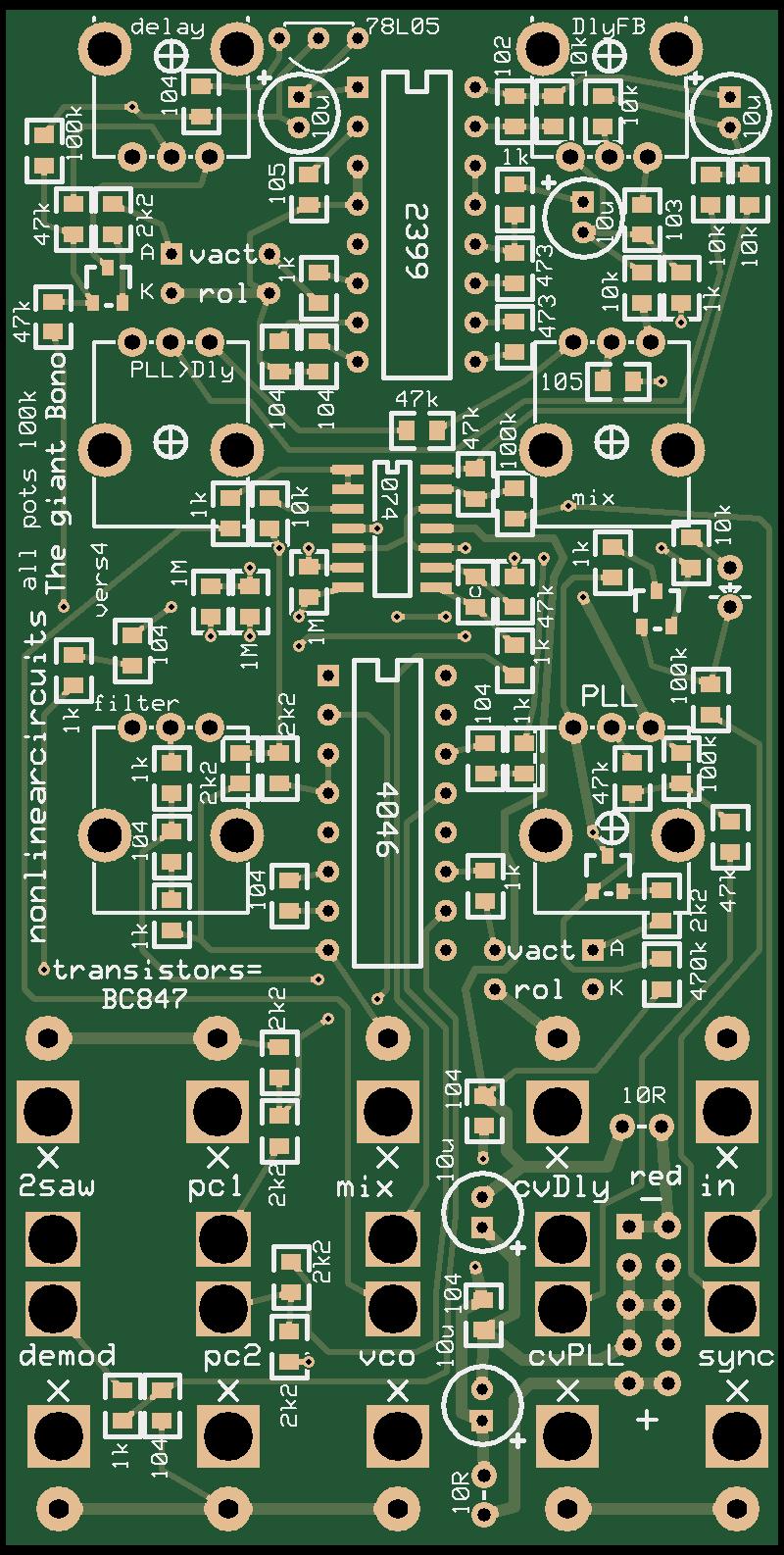
1 nonlinearcircuits giant B0N0 build & BOM VERS2 This module has its roots in the NLC DelayNoMore and Vactrol PiLL. It was partly inspired from reading several research articles on chaos in PLL circuits. It seems many PLLs can be chaotic but usually only in narrow windows, so they are usually designed to avoid operating in these regions. Of course the giant B0N0 does the exact opposite and makes matters worse by having a severely overdriven delay chip in its feedback path. The mix output is comprised of the PLL VCO signal and the delay chip s main output. VCO output is the raw PLL VCO. PC1 (phase comparator) is a 0-6V square wave, usually at audio rates. PC2 is a lot more sporadic and is best used as a burst generator. Saw out taps the signal on the PLL s timing capacitor and it runs at approx. double the frequency of the PLL VCO, a pretty dirty filthy sawtooth tho. CV output is. a CV; again it is pretty hairy but somewhat representative of whatever the circuit is doing. Mostly, as the name implies, this module will make a lot of crappy noise and is only controllable in the sense of how crappy it sounds: nutty chunks or liquid baby green. It is fun to ram anything into the input: gates/triggers/cv/audio and see what happens. Sync expects a gate or trigger, but anything is okay. The CV inputs will affect the delay and PLL sub-circuits; the PLL circuit is tuned to 1V per Couric. UPDATE 26 May 2016 found an error on the PCB, fixing this will give better range on the Courics pot. See section after the BOM. UPDATE 2 Jan 2017 found a very good mod to do.see section after Fix. BOM (Check or Mouser to see what kind of pots & jacks you need, part # given in notes, of course you can buy these anywhere, but the pictures show what type will suit) The ( ) after the component indicate how the component is labelled on the PCB. For example (c) means 100k resistors are marked on the PCB with just a c. Get extras, it is easy to drop surface mount parts or some other mishap! component quantity notes component quantity notes 100kB pot 6 Tayda: A nF (102) mm kobiconn 10 Tayda: A nF (103) style socket 47nF (473) nF (104) pin eurorack 1 1uF (105) power connector TL074 1 SOIC pitch PT DIP 1k DIP (4000 series CMOS) 2k BC847 3 SOT-23 Tayda: A k L05 1 thru hole 47k N4148 diode 1 thru hole 100k (c) R resistor 2 thru hole 220k M µF 25V (or more) electro 5 thru hole, 2 mm pin spacing single vactrol 2 any will work 10k 1 thru-hole (see MOD)
. So don t worry about it.")

2 The 78L05 does get hot because it is dropping the voltage down from 12V to 5V, so the excess is washed off as heat. I have had these running for several hours with no shutdown (78L05 will turn off if too hot). So don t worry about it. Do not install the 470k resistor, leave the pads empty. Instead install a 220k resistor between the via and the 47k as shown in the photos. If you solder blobs of solder on via and the pad of the 47k closest to the via, it is easy to place the 220k resistor between them and stretch the solder across to connect to it. See pics: FIX


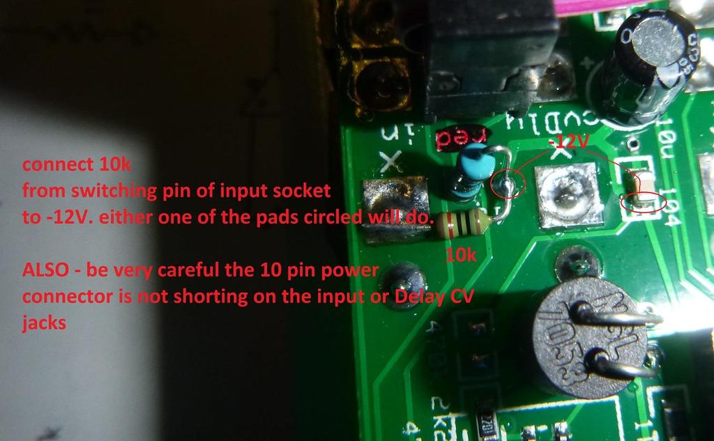
3 MOD I have found the power pins sit too close to the input and delay CV sockets. It is important to clip the two -12V pins on the bottom of the PCB so they are quite flat and install the sockets so they sit a little bit off the PCB. This pic shows enough gap so there is no short When this happened the B0n0 went quite crazy, so the mod is to connect the switching pin of the input socket to -12V via a 10k resistor. This is easily done as shown below; there are 2 nearby places to solder the 10k resistor. This mod makes the B0n0 run by itself without the need for an input signal, the Courics pot acts as a frequency control. Try it, you will like it.
4
5
6
CV Arpeggiator Rev 2 Build Documentation.
 CV Arpeggiator Rev Build Documentation. Last updated 8-0-03 The CV Arpeggiator is a modular synth project used for creating arpeggios of control voltage. It utilizes a custom programmed PIC 6F685 micro
MP3 audio amplifier. Build Instructions. Issue 2.0
 MP3 audio amplifier Build Instructions Issue 2.0 Build Instructions Before you put any components in the board or pick up the soldering iron, just take a look at the Printed Circuit Board (PCB). The components
EchoBlue Delay. PT2399 Delayayayayayay v3.0
 EchoBlue Delay PT2399 Delayayayayayay v3.0 Contents of this document are 2015 Pedal Parts Ltd. No reproduction permitted without the express written permission of Pedal Parts Ltd. All rights reserved.
SERGE Dual Extended ADSR 2017
 SERGE Dual Extended ADSR 2017 The Serge Dual Extended ADSR module contains 2 identical Extended ADSR sections, each consisting of a main pcb and a panel pcb: Please note: Orientation of the main pcb: power
Dual LPG + Timbre RANDOM*SOURCE. Dual LPG / Timbre RANDOMSOURCE.NET
 Dual LPG + Timbre The Dual LPG + Timbre section is part of the Donks module and comprises a dual low pass gate based on the famous 292C as well as the equally famous Timbre circuit adjusted to +12V and
Filthy Fack! Famous germanium 5-knobbed fuzz clone
 Filthy Fack! Famous germanium 5-knobbed fuzz clone Contents of this document are 2014 Pedal Parts Ltd. No reproduction permitted without the express written permission of Pedal Parts Ltd. All rights reserved.
Cherub Chorus. Wobbly fun based on Rick Holt s Little Angel
 Cherub Chorus Wobbly fun based on Rick Holt s Little Angel Contents of this document are 2015 Pedal Parts Ltd. No reproduction permitted without the express written permission of Pedal Parts Ltd. All rights
High Power (15W + 15W) Stereo Amplifier
 Stereo Amplifier") High Power (15W + 15W) Stereo Amplifier Build Instructions Issue 1.0 Build Instructions Before you put any components in the board or pick up the soldering iron, just take a look at the Printed Circuit
High Power (15W + 15W) Stereo Amplifier Build Instructions Issue 1.0 Build Instructions Before you put any components in the board or pick up the soldering iron, just take a look at the Printed Circuit
BMC24. MIDI TO GATE CONVERTER DOCUMENTATION. This documentation is for use with the "Euro Style" bottom board.
 BMC24. MIDI TO GATE CONVERTER DOCUMENTATION. This documentation is for use with the "Euro Style" bottom board. A. USING THE MIDI TO GATE CONVERTER B. PARTS LIST C. BUILDING INSTRUCTIONS D. SCHEMATICS Revision.
DELUXE STEREO AMPLIFIER KIT
 ESSENTIAL INFORMATION BUILD INSTRUCTIONS CHECKING YOUR PCB & FAULT-FINDING MECHANICAL DETAILS HOW THE KIT WORKS CREATE YOUR OWN SPEAKER DOCK WITH THIS DELUXE STEREO AMPLIFIER KIT Version 2.0 Build Instructions
Raspberry-Pi Shield: Binary-Coded-Decimal Clock
 Raspberry-Pi Shield: Binary-Coded-Decimal Clock ASSEMBLY INSTRUCTIONS What is it? This kit builds a binary-coded-decimal clock, driven by a Raspberry-Pi (which should be mounted on the back). This is a
Fuzz Rite V2.0. Mosrite FuzzRite / Gus Rite Fuzz
 Fuzz Rite V2.0 Mosrite FuzzRite / Gus Rite Fuzz Contents of this document are 2016 Pedal Parts Ltd. No reproduction permitted without the express written permission of Pedal Parts Ltd. All rights reserved.
Transcendent Frequency Counter
 Transcendent Frequency Counter with blue 2 x 16 LCD display This manual will guide you how to assemble, test and operate this frequency counter KIT. Features: The transcendent counter has two input channels
The Sudden Storm Kit. by QRPme. Builder s Guide. version4.2. for. Sudden Storm ][ Ver4 (red pcb) Updated 01/10/2012
![The Sudden Storm Kit. by QRPme. Builder s Guide. version4.2. for. Sudden Storm ][ Ver4 (red pcb) Updated 01/10/2012](/thumbs/75/72448638.jpg "The Sudden Storm Kit. by QRPme. Builder s Guide. version4.2. for. Sudden Storm ][ Ver4 (red pcb) Updated 01/10/2012") The Sudden Storm Kit by QRPme Builder s Guide version4.2 for Sudden Storm ][ Ver4 (red pcb) Updated 01/10/2012 Open the can and the adventure begins 1 Organize the parts and take an inventory Bill of Materials
The Sudden Storm Kit by QRPme Builder s Guide version4.2 for Sudden Storm ][ Ver4 (red pcb) Updated 01/10/2012 Open the can and the adventure begins 1 Organize the parts and take an inventory Bill of Materials
Tone Bender Mk III. Grandaddy of super-cool vintage fuzz tone
 Tone Bender Mk III Grandaddy of super-cool vintage fuzz tone Contents of this document are 2014 Pedal Parts Ltd. No reproduction permitted without the express written permission of Pedal Parts Ltd. All
Advanced Lantern 1.0 Kit. Introduction to the Advanced Lantern 1.0 Kit
 Advanced LED Lantern 1.0 Instruction Manual Eastern Voltage Research, LLC Introduction to the Advanced Lantern 1.0 Kit Thank you for purchasing the Advanced Lantern 1.0 Kit. This kit is an advanced microprocessor
TuBbika SMR-4-PLUS voicecard
 TuBbika SMR-4-PLUS voicecard Assembly instructions We assume you know soldering. If you don t, look first at this tutorial. Be patient! And if you have any doubt, head to the forum never be afraid to ask!
Exclusive 2.5 GHz Frequency Counter
 Exclusive 2.5 GHz Frequency Counter with blue 2 x 16 LCD display This manual will guide you how to assemble, test and tune this frequency counter KIT. Features: Frequency range from 5 MHz to 2.5GHz Factory
LED Sequencer 1.0 / 1.5
 LED Sequencer 1.0 / 1.5 Instruction Manual Eastern Voltage Research, LLC May 2012, Rev 2 1 http://www.easternvoltageresearch.com Introduction to the LED Sequencer 1.0 Thank you for purchasing the LED Sequencer
Little Screamerv2.0. Stripped-back, bufferless Tube Screamer
 Little Screamerv2.0 Stripped-back, bufferless Tube Screamer Contents of this document are 2016 Pedal Parts Ltd. No reproduction permitted without the express written permission of Pedal Parts Ltd. All
dual bipolar voltage controlled step sequencer DIY ASSEMBLY MANUAL v1.03
 dual bipolar voltage controlled step sequencer DIY ASSEMBLY MANUAL v1.03 Contents Contents... 2 Introduction... 3 Part Sourcing Notes for Non Kit Builders... 3 Eurorack Kit Assembly... 4 Resistors and
Deep Vibes. Wobbly Optical Vibe action
 Deep Vibes Wobbly Optical Vibe action Contents of this document are 2018 Pedal Parts Ltd. No reproduction permitted without the express written permission of Pedal Parts Ltd. All rights reserved. Important
QUANTOM DEFRAKULATOR Build Document last updated june 2018 for PCB version 1.0
 QUANTOM DEFRAKULATOR Build Document last updated june 2018 for PCB version 1.0 The Quantom Defrakulator is a drone synthesizer with 3 square wave oscillators and one LFO (low frequency oscillator). Each
Electronics Construction Manual
 Electronics Construction Manual MitchElectronics 2018 Version 1 07/05/2018 www.mitchelectronics.co.uk CONTENTS Introduction 3 How To Solder 4 Resistors 5 Capacitors 6 Diodes and LEDs 7 Switches 8 Transistors
Creep Cluster Build Document. V5 - November 2018
 Creep Cluster Build Document. V5 - November 2018 Dual triangle oscillators are hard-switched by a fast squarewave. Then the signal goes into a resonant lowpass filter. Sounds vary from deep rumbling drones
BMC056. Utility Buttons Last updated
 BMC056. Utility Buttons Last updated -0-209 If you have any questions, or need help trouble shooting, please e-mail Michael@Bartonmusicalcircuits.com I Controls/Inputs/Outputs II Schematic III Construction
RKP08 Component List and Instructions
 RKP08 Component List and Instructions PCB layout Constructed PCB RKP08 Scematic RKP08 Project PCB Page 1 Description The RKP08 project PCB has been designed to use PIC microcontrollers such as the Genie
DIY Assembly Manual for the LPZW.modules PO-Series Adapter Version 1.0
 DIY Assembly Manual for the LPZW.modules PO-Series Adapter Version 1.0 Introduction The LPZW.module PO-Series Adapter has five functions: hold the PO in your Eurorack supply power to the PO from bus-power
Patch Bay. Model 9746 Assembly and Using Manual PAiA Corporation
 Patch Bay Model 9746 Assembly and Using Manual This second-generation 9700-series processing element for modular sound synthesizers is designed to provide great sound and excellent value. A two-section
Advanced Strobe 1.0 Kit
 Kit Instruction Manual Eastern Voltage Research, LLC December 2013, Rev 1 1 http://www.easternvoltageresearch.com Kit Introduction to the Kit Thank you for purchasing the Kit. If you are looking for a
Uzebox Kit Assembly Guide
 Uzebox Kit Assembly Guide V1.3 Page 1 of 18 Revision History Version Date Author Description 1.0 01-Nov-2012 A.Bourque Initial release 1.1 6-Nov-2012 A.Bourque Minor corrections 1.2 28-Jan-2014 A.Bourque
Construction Construction Instructions
 Semi-Virtual Diskette SVD Construction Construction Instructions PCB version 2.0 September 2004 Eric J. Rothfus Table of Contents Table of Contents... i Parts List...1 Construction Overview...5 PCB Construction...
SM010, Assembly Manual PCB Version 1.0
 180 SM010, Assembly Manual MATRIXARCHATE 16 8 IO SEQUENTIAL MATRIX SIGNAL ROUTER SM010 1 2 1 2 3 4 5 3 4 5 6 7 8 9 10 11 12 6 7 8 9 10 11 12 13 14 15 16 PROGRAM A B C D E F G H f1 f2 20.000 180 SSSR Labs
Fuzz Face. Vintage fuzz with optional voltage inverter
 Fuzz Face Vintage fuzz with optional voltage inverter Contents of this document are 2014 Pedal Parts Ltd. No reproduction permitted without the express written permission of Pedal Parts Ltd. All rights
Installation/assembly manual for DCC/Power shield
 Installation/assembly manual for DCC/Power shield The DCC circuit consists of the following components: R1/R6 R2/R3 R4/R5 D1 C2 2 kω resistor ½ Watt (colour code Red/Black/Black/Brown/Brown) 10 kω resistor
The Basic Counter. Hobby Electronics Soldering Kit. Instruction Guide
 The Basic Counter Hobby Electronics Soldering Kit Instruction Guide TM For the best outcome, follow each step in order. We recommend reading this guide entirely before you get started. Tools required:
STAGE INTERCOM KIT 1.1 SPECIFICATION. General: The lower section is a small power amplifier designed to drive headphones or a small 8ohm speaker.
 STAGE INTERCOM KIT Version 2.1.1 - March 2018 - EduTek Ltd 1.0 DESCRIPTION This intercom module comprises of two separate circuits sharing the same supply. The upper section is a pre-amplifier designed
Super Skwisher. Ross Compressor +++
 Super Skwisher Ross Compressor +++ Contents of this document are 2015 Pedal Parts Ltd. No reproduction permitted without the express written permission of Pedal Parts Ltd. All rights reserved. Important
USER S GUIDE for the. Polyglot. by the staff of Buchla USA V1.3 4/5/ Buchla USA
 USER S GUIDE for the Polyglot by the staff of Buchla USA V1.3 4/5/18 2018 Buchla USA Polyglot 40HP Eurorack active adaptor: The Polyglot is for adapting cables, converting voltage ranges, and powering
Pacific Antenna Two Tone Generator
 Pacific Antenna Two Tone Generator Description Our Two Tone Generator kit provides two non-harmonic, sine wave signals for testing audio circuits Outputs of approximately 700Hz and 1900Hz and the combination
You need the following components to assemble the Black n Wood Nixie Clock circuit board:
 You need the following components to assemble the Black n Wood Nixie Clock circuit board: Quantity Designator Description 1 Battery Battery, CR1220 1 Battery Battery holder 3 Button 1, Button 2, Button
Post Tenebras Lab. Written By: Post Tenebras Lab
 Post Tenebras Lab PTL-ino is an Arduino comptaible board, made entirely out of through-hole components. It is a perfect project to learn how to solder and start getting into the world of micro controllers.
IC Big Muff 78. Chip-based Big Muff Pi. Smooooooth!
 IC Big Muff 78 Chip-based Big Muff Pi. Smooooooth! Contents of this document are 2015 Pedal Parts Ltd. No reproduction permitted without the express written permission of Pedal Parts Ltd. All rights reserved.
Electronics Construction Manual
 Electronics Construction Manual MitchElectronics 2019 Version 3 04/02/2019 www.mitchelectronics.co.uk CONTENTS Introduction 3 How To Solder 4 Resistors 5 Capacitors 6 Diodes and LEDs 7 Switches 8 Transistors
Uzebox Kit Assembly Guide
 Uzebox Kit Assembly Guide V1.7 Page 1 of 21 Revision History Version Date Author Description 1.0 01-Nov-2012 A.Bourque Initial release 1.1 6-Nov-2012 A.Bourque Minor corrections 1.2 28-Jan-2014 A.Bourque
UF-3701 Power Board Construction Guide
 Page 1/5 Soldering and Part Placement See the Chapter 3 of the MIT 6270 Manual for information on electronic assembly, including soldering techniques and component mounting. Construction Information All
Morse Code Practice Oscillator
 Features Description Keyer speed range: Limited only by keying source True Sine wave tone output Tone Volume Control Tone Frequency Control Internal Speaker 1/8 External Speaker/Headphone Jack RCA Key
IR TRANSMITTER BLOK PCB ASSEMBLY INSTRUCTIONS. Copyright EduTek Ltd Rev. 2
 IR TRANSMITTER BLOK PCB ASSEMBLY INSTRUCTIONS Copyright EduTek Ltd Rev. 2 Circuit Details The circuit is shown below with a parts list of components. Check through this list and identify each component.
Mini Fuzz Face. Vintage fuzz in a neat little package
 Mini Fuzz Face Vintage fuzz in a neat little package Contents of this document are 2016 Pedal Parts Ltd. No reproduction permitted without the express written permission of Pedal Parts Ltd. All rights
Digital Flame 1.0 Kit
 Digital Flame 1.0 Kit Instruction Manual Eastern Voltage Research, LLC June 2012, Rev 1 1 http://www.easternvoltageresearch.com Introduction to the Digital Flame 1.0 Kit Thank you for purchasing the Digital
UK-electronic Manual Miniverb V2 with the Belton BTDR-2-X Modul
 UK-electronic 2015 Manual Miniverb V2 with the Belton BTDR-2-X Modul Page 1 2...Introduction, Short circuit description Page 3 4...Basics Page 5 6...Bill of material Page 5...7...Soldering the pcb Page
Digital Candle 1.0 Kit
 Kit Instruction Manual Eastern Voltage Research, LLC June 2012, Rev 1 1 http://www.easternvoltageresearch.com Introduction to the Kit Thank you for purchasing the Kit. This kit is definitely a favorite
TKEY-1. CW touch key. (no electromechanical contacts) Assembly manual. Last update: June 20,
 Assembly manual. Last update: June 20,") TKEY-1 CW touch key (no electromechanical contacts) Assembly manual Last update: June 20, 2017 ea3gcy@gmail.com Updates and news at: www.ea3gcy.com Thanks for constructing the TKEY-1A CW touch key Have
TKEY-1 CW touch key (no electromechanical contacts) Assembly manual Last update: June 20, 2017 ea3gcy@gmail.com Updates and news at: www.ea3gcy.com Thanks for constructing the TKEY-1A CW touch key Have
MAIN PCB (The small one)
") THANKS FOR CHOOSING ONE OF OUR KITS! This manual has been written taking into account the common issues that we often find people experience in our workshops. The order in which the components are placed
THANKS FOR CHOOSING ONE OF OUR KITS! This manual has been written taking into account the common issues that we often find people experience in our workshops. The order in which the components are placed
Make Kits and Casemods
 Make Kits and Casemods This weekend, you ll learn how to make a Minty Boost usb charger and a Daisy mp3 player. After you put these together you can put them into customized cases. I made my charger fit
W0EB/W2CTX DSP Audio Filter Construction Manual V3.02.1
 W0EB/W2CTX DSP Audio Filter Construction Manual V3.02.1 Manual and photographscopyright W0EB/W2CTX, January 01, 2019. This document may be freely copied and distributed so long as no changes are made and
Colecovision 5v Memory Mod Installation
 Colecovision 5v Memory Mod Installation The Colecovision suffers from common failure points: the power supply, power switch, and 4116 DRAM. The power supply suffers from poor soldering, the power switch
RC Tractor Guy Controller V2.1 Assembly Guide
 RC Tractor Guy Controller V. Assembly Guide Features 0 Push button inputs Dual axis thumb sticks with built-in push button Rotary encoders with built-in push button MCU Socket to suit Meduino Mega 560
HUB-ee BMD-S Arduino Proto Shield V1.0
 HUB-ee BMD-S Arduino Proto Shield V1.0 User guide and assembly instructions Document Version 1.0 Introduction 2 Schematic 3 Quick user guide 4 Assembly 5 1) DIP Switches 5 2) Micro-MaTch Connector Headers
LED Knight Rider. Yanbu College of Applied Technology. Project Description
 LED Knight Rider Yanbu College of Applied Technology Project Description This simple circuit functions as a 12 LED chaser. A single illuminated LED 'walks' left and right in a repeating sequence, similar
This presentation will..
 Component Identification: Digital Introduction to Logic Gates and Integrated Circuits Digital Electronics 2014 This presentation will.. Introduce transistors, logic gates, integrated circuits (ICs), and
HALO. Easy. Distortion / Sustainer, Fuzz ( )
") PROJECT NAME HALO BASED ON Electro-Harmonix Big Muff Pi BUILD DIFFICULTY Easy EFFECT TYPE DOCUMENT VERSION Distortion / Sustainer, Fuzz 1.0.0 (2018-07-04) PROJECT SUMMARY One of the most classic guitar
PROJECT NAME HALO BASED ON Electro-Harmonix Big Muff Pi BUILD DIFFICULTY Easy EFFECT TYPE DOCUMENT VERSION Distortion / Sustainer, Fuzz 1.0.0 (2018-07-04) PROJECT SUMMARY One of the most classic guitar
DIGWDF Ren-W Universal Assembly Guide
 DIGWDF Ren-W Universal Assembly Guide Overview Before starting, be sure to read through the entire guide to familiarize yourself with the parts and parts locations. In many cases, you may not need to install
solutions for teaching and learning
 RKP18Motor Component List and Instructions PCB layout Constructed PCB Schematic Diagram RKP18Motor Project PCB Page 1 Description The RKP18Motor project PCB has been designed to use PIC microcontrollers
EE 354 August 1, 2017 Assembly of the AT89C51CC03 board
 EE 354 August 1, 2017 Assembly of the AT89C51CC03 board The AT89C51CC03 board comes as a kit which you must put together. The kit has the following parts: No. ID Description 1 1.5" x 3.25" printed circuit
QRPGuys Single Lever Keyer/Paddle
 QRPGuys Single Lever Keyer/Paddle First, familiarize yourself with the parts and check for all the components. If a part is missing, please contact us and we will send one. You must use qrpguys.parts@gmail.com
LushOne Inca Synth Module Build Instructions
 LushOne Inca Synth Module Build Instructions Getting started If you can build the LushOne base module then then building the Inca should be easy Remember: Accuracy and neatness is more important than speed
Sprinkler Controller Assembly Manual
 Sprinkler Controller Assembly Manual V1.0 Doug Jackson VK1ZDJ September 2010 Licence The Sprinkler Controller Design, PCB layout, Manual, and Firmware is Copyright 2010, by Douglas Jackson, VK1ZDJ. This
A Homebrew AUX-7 Board for the Drake TR7 and R7
 Overview A Homebrew AUX-7 Board for the Drake TR7 and R7 OK, so you don't really need an AUX-7 board to be able to transmit and receive on all frequencies with the TR7. But, there are some advantages to
GLiPIC Ver C Assembly manual Ver 1.0
 GLiPIC Ver C Assembly manual Ver 1.0 Last Rev 1.1 Oct 30, 2001 Author: Ranjit Diol Disclaimer and Terms of Agreement As with any kit, only the individual parts supplied are guaranteed against defects and
Device: PLT This document Version: 1. For hardware Version: 1. For firmware Version: Date: 9 May 2014
 Device: PLT-2001 This document Version: 1 For hardware Version: 1 For firmware Version: 5.00 Date: 9 May 2014 Description: LED Matrix Display Driver board PLT-2001v1 datasheet Page 2 Contents Introduction...
MuP-Security. Ver Aug-14
 MuP-Security Ver. 1.0 18-Aug-14 bigmick58@bigpond.com Preamble: The MuP-Security project came about due to a request from David Hall, a member of `The Back Shed Forum, for a board that could plug into
Images Scientific OWI Robotic Arm Interface Kit (PC serial) Article
 Article") Images Scientific OWI Robotic Arm Interface Kit (PC serial) Article Images Company Robotic Arm PC Interface allows real time computer control and an interactive script writer/player for programming and
Images Scientific OWI Robotic Arm Interface Kit (PC serial) Article Images Company Robotic Arm PC Interface allows real time computer control and an interactive script writer/player for programming and
ZX81 ULA Replacement. Installing the ULA
 ZX81 ULA Replacement The ZX81 ULA replacement is a plug in pin compatible clone of the original ZX81 ULA with a bit of an extra boost. Installing the ULA The replacement ula includes circuitry to directly
Olfaction Satisfaction Week #10 April 5, 2006 Senior Design Team 8
 Olfaction Satisfaction Week #10 April 5, 2006 Senior Design Team 8 Work Completed The first task for Emily this week was to finish debugging the circuit. The sound chip problem was finally figured out.
Button Code Kit. Assembly Instructions and User Guide. Single Button Code Entry System
 Button Code Kit Single Button Code Entry System Assembly Instructions and User Guide Rev 1.0 December 2009 www.alan-parekh.com Copyright 2009 Alan Electronic Projects Inc. 1. Introduction... 4 1.1 Concept
KK1L 2x6 Antenna Switch Relay Controller / Dual Band Decoder Basic Assembly Version 4.8 (new 24-Aug-2009) Parts List updated 19-AUG-2016
 Parts List updated 19-AUG-2016") KK1L 2x6 Antenna Switch Relay Controller / Dual Band Decoder Basic Assembly Version 4.8 (new 24-Aug-2009) Parts List updated 19-AUG-2016 Ronald Rossi, KK1L http://home.comcast.net/~kk1l Design Features:
KK1L 2x6 Antenna Switch Relay Controller / Dual Band Decoder Basic Assembly Version 4.8 (new 24-Aug-2009) Parts List updated 19-AUG-2016 Ronald Rossi, KK1L http://home.comcast.net/~kk1l Design Features:
Hauptwerk Hardware 2016
 Hauptwerk Hardware Interface Board for the Universal Midi Encoder User Manual Page 1 Release 1.2 February 2016 Table of Contents Introduction...3 Board Overview...4 IMPORTANT PLEASE READ...5 Mounting...6
Step 1 - Modifying the power-supply from 12 to 16 Volts Increasing the power-supply voltage to 16V increases the headroom and reduces distortion. Also
 Dada Electronics - Quad 33 Revision - Illustrated Guidelines V 2.4 First of all, thanks for your purchase of our upgrade kit! Hereunder, you will find the step-by-step guidelines for upgrading the Quad
Storage Card Interface Kit
 Storage Card Interface Kit for MultiMediaCards(MMC) and Secure Digital Cards (SD) MMSD3K The MMSD3K is complete development kit interfaced to a SD or MMC card. This board ideal for projects that involve
Datacorder Kit MitchElectronics 2019
 Datacorder Kit MitchElectronics 2019 www.mitchelectronics.co.uk CONTENTS Schematic 3 How It Works 4 How To Use 5 Materials 6 Construction 7 Important Information 8 Page 2 SCHEMATIC Page 3 HOW IT WORKS
3PRR. FX TYPE: Utility 2015 madbeanpedals W x 1.11 H change-log: Removed 10R current limiting resistor.
 3PRR FX TYPE: Utility 2015 madbeanpedals 1.815 W x 1.11 H 2015 change-log: Removed 10R current limiting resistor. This PCB is designed for the typical BLUE 3PDT footswitch. Other footswitches may or may
SRI-02 Speech Recognition Interface
 SRI-02 Speech Recognition Interface Data & Construction Booklet The Speech Recognition Interface SRI-02 allows one to use the SR-07 Speech Recognition Circuit to create speech controlled electrical devices.
Propeller Project Board USB (#32810)
") Web Site: www.parallax.com Forums: forums.parallax.com Sales: sales@parallax.com Technical: support@parallax.com Office: (916) 624-8333 Fax: (916) 624-8003 Sales: (888) 512-1024 Tech Support: (888) 997-8267
Web Site: www.parallax.com Forums: forums.parallax.com Sales: sales@parallax.com Technical: support@parallax.com Office: (916) 624-8333 Fax: (916) 624-8003 Sales: (888) 512-1024 Tech Support: (888) 997-8267
TEMPEST PROJECT NAME. BASED ON Friedman BE-OD / Dirty Shirley. BUILD DIFFICULTY Intermediate. DOCUMENT VERSION Amp-Like Distortion 1.0.
 PROJECT NAME TEMPEST BASED ON Friedman BE-OD / Dirty Shirley BUILD DIFFICULTY Intermediate EFFECT TYPE DOCUMENT VERSION Amp-Like Distortion.0. (09-0-08) PROJECT SUMMARY A pedal recreation of the Friedman
QUASAR PROJECT KIT # ATMEL AVR PROGRAMMER
 This kit is a simple but powerful programmer for the Atmel AT90Sxxxx ( AVR ) family of microcontrollers. The Atmel AVR devices are a low-power CMOS 8-bit microcontroller using a RISC architecture. By executing
FuzzD s 3PDT Direct Connect DaughterBoard
 FuzzD s 3PDT Direct Connect DaughterBoard Minimising your wiring woes Contents of this document are 2015 Pedal Parts Ltd. No reproduction permitted without the express written permission of Pedal Parts
SDS_VCO DIY INSTRUCTIONS
 SDS_VCO DIY INSTRUCTIONS Thankyou for your purchase of the fantastic SDS_VCO DIY kit! First, make sure all of the parts are in the kit: SEMICONDUCTORS: 1 * PIC18F46K22I/P PREPROGRAMMED PROCESSOR 1 * MCP4921
Assembly Instructions (8/14/2014) Your kit should contain the following items. If you find a part missing, please contact NeoLoch for a replacement.
 Your kit should contain the following items. If you find a part missing, please contact NeoLoch for a replacement.") NeoLoch NLT-28P-LCD-5S Assembly Instructions (8/14/2014) Your kit should contain the following items. If you find a part missing, please contact NeoLoch for a replacement. Kit contents: 1 Printed circuit
NeoLoch NLT-28P-LCD-5S Assembly Instructions (8/14/2014) Your kit should contain the following items. If you find a part missing, please contact NeoLoch for a replacement. Kit contents: 1 Printed circuit
MICRO-TRAK 300 MANUAL VER 1.4
 MICRO-TRAK 300 MANUAL VER 1.4 The Micro-Trak 300 Version 1.4 is a miniature APRS (Automatic Position Reporting System) transmitter operating on the North American APRS frequency standard of 144.390 MHz.
University of Florida EEL 4744 Drs. Eric M. Schwartz, Karl Gugel & Tao Li Department of Electrical and Computer Engineering
 Page 1/9 Revision 1 OBJECTIVES In this document you will learn how to solder and to debug a board as you are building it. REQUIRED MATERIALS Website documents o UF 68HC12 Development Board Manual (board
TIME WIZARD MULTI CLOCK DIVIDER BUILDING GUIDE
 TIME WIZARD MULTI CLOCK DIVIDER BUILDING GUIDE Table of Contents 0. Components List + Tools 0. PCB Sides 03. PCB Assembly 04_. Diode N448 04_. Laying Resistors 04_3. Capacitors 04_4. Quartz 04_5. 78L05
MAIN PCB (The small one with the square cut out from one side)
") THANKS FOR CHOOSING ONE OF OUR KITS! This manual has been written taking into account the common issues that we often find people experience in our workshops. The order in which the components are placed
THANKS FOR CHOOSING ONE OF OUR KITS! This manual has been written taking into account the common issues that we often find people experience in our workshops. The order in which the components are placed
Lunar Shot Trem. CultureJam s Shoot The Moon - a stripped back Tremulus Lune
 unar Shot Trem CultureJam s Shoot The Moon - a stripped back Tremulus une Contents of this document are 2017 Pedal Parts td. No reproduction permitted without the express written permission of Pedal Parts
Copyright 2008, 2009 Grandad s Electronics Seattle, Washington, USA. INSTRUCTION MANUAL Model XTAL1. XTAL1 (assembled)
") Copyright 2008, 2009 Grandad s Electronics Seattle, Washington, USA INSTRUCTION MANUAL Model XTAL1 XTAL1 (assembled) 1 XTAL1 Manual, 12/23/2008 Assembly Instructions This kit assumes that the purchaser
Copyright 2008, 2009 Grandad s Electronics Seattle, Washington, USA INSTRUCTION MANUAL Model XTAL1 XTAL1 (assembled) 1 XTAL1 Manual, 12/23/2008 Assembly Instructions This kit assumes that the purchaser
DIY Line Tracking Smart Car with AT89C2051
 DIY Line Tracking Smart Car with AT89C2051 1. Introduction: A DIY Smart Car design involves mechanical structure, electronic based sensor principle, automatic control, and even knowledge of microcontroller
5U Oakley Modular Series. Multimix issue 5 Four channel mixer with reversible attenuators
 Oakley Sound Systems 5U Oakley Modular Series Multimix issue 5 Four channel mixer with reversible attenuators Builder's Guide V5.1 Tony Allgood Oakley Sound Systems CARLISLE United Kingdom Introduction
QRPGuys Digital Dial/Frequency Counter
 QRPGuys Digital Dial/Frequency Counter First, familiarize yourself with the parts and check for all the components. If a part is missing, please contact us and we will send one. You must use qrpguys.parts@gmail.com
B.Y.O.C. MK2 Kit Instructions
 B.Y.O.C. MK2 Kit Instructions Parts Checklist.....page 2 Populating the Circuit Board......page 3-5 Assembly......page 6 Wiring......page 7 Installing the LED and Mounting the PCB...page 8-9 Finish up...page
DIY Build Instructions PLITKA REPLICANT (BUFFERED MULTIPLE)
") DIY Build Instructions PLITKA REPLICANT (BUFFERED MULTIPLE) First of, thank you for your purchase of the PLITKA REPLICANT DIY Kit (2 x PCB, Front Panel). If you are a DIY Synth novice, you have selected
DIY Build Instructions PLITKA REPLICANT (BUFFERED MULTIPLE) First of, thank you for your purchase of the PLITKA REPLICANT DIY Kit (2 x PCB, Front Panel). If you are a DIY Synth novice, you have selected