MaXiO System Manual INDEX 1. Introduction Hardware Installation... 15
|
|
|
- Laurence Lawrence
- 5 years ago
- Views:
Transcription
1 INDEX 1. Introduction About this manual What s in the Box? Key Features PCI host card EX8000 2U Rack breakout box PCI host card E.D.I connector M.D.I connector EX Front Panel Input Channel Section Front Panel Power Section Back Panel Power Section Front Panel Clock & Control Section Back Panel Clock Section Analog Outputs & Inserts Digital I/O (Back Panel) M.D.I breakout cable ( for XD only) Word Clock I/O MIDI I/O S/PDIF Digital I/O breakout box Front Panel Input Channel Section MIDI signal LEDs & Phantom power Analog Outputs Digital I/O MIDI I/O and M.D.I connector Hardware Installation Minimum System Requirements Installation of PCI host card EX8000 connection connection
2 4. Driver Installation Control Panel Pull Down Menu Input Section Input signal path block diagram Output Section Master Section Master & Output signal path block diagram display section State System Clock I/O Config The EX8000 control panel Applications Setup Windows Multimedia setup Cubase and Nuendo Cakewalk SONAR Wavelab Tracktion DirectWIRE What is DirectWIRE? DirectWIRE Panel DirectWIRE examples Technical Specifications END USER WARRANTY V2 JULY
3 1. Introduction Thank you for choosing the ESI. The covers the PCI host card and all extensions such as the EX8000 rack unit and the 032 breakout box. XD is a complete 24-bit / 192 khz recording system designed to handle up to 32 input channels and 32 output channels simultaneously. The basic XD system consists of the PCI host card and one EX8000, a 2U-rack space unit with 8 analog input channels, 8 analog output channels, ADAT, and digital I/O. The PCI card is equipped with four FireWire-like E.D.I (ESI Digital Interface) ports, each capable of individually supporting one breakout box with E.D.I connection like the EX8000. There is also a single M.D.I (Multiple Digital Interface) multichannel connector on the PCI host card for future expansion. This gives the XD system 32 input and 32 output channel capability on one single interface card. By default, the M.D.I connection of the PCI host card provides coaxial S/PDIF I/O, Word Clock I/O and a 1 in / 1 out MIDI interface. Another member of the series, the 032 s 4 ADAT inputs and 4 ADAT outputs provide 32 input and 32 output channels, via a single PCI card and its breakout box. Now you can connect your computer to up to 4 ADAT compatible devices and use them simultaneously for multi track recording. There is more: next to S/PDIF I/O and a full 16 channel MIDI interface 032 provides a high quality stereo analog input with microphone preamps (48V phantom power support), a high end 123dB[A] ADC, and 120dB[A] DAC. This turns 032 into a reference audio hardware providing audio quality at a level that has not been achieved before in this price range. The 032 can be expanded via its E.D.I (ESI Digital Interface) connectors into a full XD system by adding one or several EX8000 units. On PC systems, systems are equipped with ESI's unique and powerful EWDM driver for perfect compatibility with Windows XP and 2000, offering ultra low-latency performance with all popular digital audio software applications including Nuendo, Cubase, Gigastudio, Cakewalk, Sonar, Logic, Samplitude and Sequoia. 1.1 About this manual The XD system and 032 are very flexible and provides a huge number of features and options. In order to use it to its full capabilities, you need to understand the usage and concepts. We know that most users do not like to read long manuals such as this (we don t like it either...) because of that, we have tried to keep this manual as short as possible. Please take your time to read it completely. 3
4 1.2 What s in the Box? Your XD package contains the following: PCI host card Driver CD with UAT bundle software Tracktion Software CD (this document) M.D.I breakout cable standard IEEE1394 connection cable EX8000 2U rack power cable for EX8000 EX8000 User's Guide Your 032 package contains the following: PCI host card Driver CD with UAT bundle software Tracktion Software CD (this document) The M.D.I connection cable (between PCI host card and 032 breakout box) 1.3 Key Features PCI host card 4 32bit PCI Interface with PCI Bus-Mastering support PCI slot compatibility designed to suit +3.3V and/or +5V PCI slots 24bit /192 khz audio interface maximum 32 input and 32 output channels Full Duplex simultaneous record / playback 4 E.D.I & 1 M.D.I connectors Coaxial digital I/O support up to 24-bit / 192 khz (built on M.D.I breakout cable for XD only) Word Clock I/O: Fs / 256*Fs, BNC connector (built on M.D.I breakout cable for XD only) 1 in / 1 out, 16 channel MIDI (built on M.D.I breakout cable for XD only) Supports EWDM driver: MME/WDM, DirectSound, ASIO 2.0, GSIF Windows XP/2000 compatible EX8000 2U Rack E.D.I Connector High-end quality 24-bit / 192 khz ADC with 123dB(a) dynamic range
5 High-end quality 24-bit / 192 khz DAC with 120dB(a) dynamic range 8 balanced analog inputs with combo (XLR / TRS) connectors featuring ESI s newly developed 'XD-PRE' high precision & ultra low noise (-135.5dBu) microphone preamplifier on each analog input channel with support for +48V phantom power Mic/Line selection switch and gain control for each analog input channel 8 inserts (one for each analog input channel) with 1/4" connectors 8 balanced analog outputs with XLR connectors (+4dBu) 8 balanced/unbalanced analog outputs with TRS connectors (-10dBV) Headphone amplifier with volume control 8 channel digital I/O in AES/EBU (XLR connectors) and coaxial S/PDIF (RCA connectors) format, supporting up to 24-bit / 192 khz 8 channel ADAT optical digital I/O with S/MUX support 10 step LED level meters on front panel for all channels (input and output) Supported sample rates: 44.1, 48, 88.2, 96, and 192 khz Word Clock input: Fs / 256*Fs (via BNC connector) breakout box M.D.I connector High-end quality 24-bit / 192 khz ADC with 123dB(a) dynamic range High-end quality 24-bit / 192 khz DAC with 120dB(a) dynamic range 2 balanced analog inputs with combo (XLR / TRS) connectors featuring ESI s newlydeveloped 'XD-PRE' high precision & ultra low noise (-135.5dBu) microphone preamplifier on each analog input channel with support for +48V phantom power Mic/Line/Hi-Z selection switch and gain control for each analog input channel 2 balanced analog outputs with XLR connectors (+4dBu) 2 balanced/unbalanced analog outputs with TRS connectors (-10dBV) Headphone amplifier with volume control 2 channel digital I/O in coaxial S/PDIF (RCA connectors) format, supports up to 24-bit / 192 khz resolution/sample rate 32 channel ADAT optical digital I/O Supported sample rates: 44.1, 48, 88.2, 96, and 192 khz Word Clock input and output: Fs / 256*Fs (via BNC connector) 1 in / 1 out, 16 channel MIDI 5
6 2.1 PCI host card E.D.I connector E.D.I is ESI s exclusive digital audio transfer protocol that delivers an 8 channel audio stream (with up to 24-bit / 192 khz). E.D.I uses an IEEE1394/FireWire cable for the connection of E.D.I compatible devices like EX8000 to the PCI host card. The PCI host card has 4 E.D.I connectors that allow you to connect 4 devices such as EX8000 simultaneously, providing 32 input and 32 output channels M.D.I connector The M.D.I connection can handle 32 digital input and 32 digital output streams for the extension of 032 breakout box. * In the basic XD system, the PCI card connects to the special M.D.I breakout cable (described below). 6
7 2.2 EX Front Panel Input Channel Section 1 2 Analog Balanced XLR / TRS (Combo) Input Connector EX8000 provides 8 combo connectors (XLR and 1/4" TRS) on the front panel that are used as balanced analog inputs for line level signals and microphone connection (via XLR). Microphone Input Selection Switch Every input channel can be used for line level or microphone signals. When this switch is enabled, a microphone can be connected via XLR. In this case phantom power is supplied (when enabled, check 7 ). When the switch is not enabled, the XLR and TRS inputs are used for balanced line level signals Input Gain Control Controls the amount gain applied to the input signal from the XLR or TRS connector of specific channel. Microphone signals can be amplified with 48dB maximum, line level signals with up to 30dB Analog Input / Output Level Meter The two level meters indicate the signal level for the analog inputs and outputs. The level meter on the left shows the input signal; the level meter on the right shows the output signal of the corresponding channel. A range from 0dB to 60dB in 10 db-steps is displayed. 7
8 2.2.2 Front Panel Power Section Power Indicator LED Power Switch Phantom Power Switch +48V DC phantom power (for balanced condenser microphones) will be supplied via every XLR input connector when this button is enabled. Note that this affects only those input channels that are set to receive microphone signals (check 2 ) ! CAUTION Before you turn on the phantom power switch, you must make sure to connect your microphones to the XLR inputs (with balanced cables). After you have turned on the phantom power switch, you should not connect or disconnect a microphone to any of the input connectors Back Panel Power Section 22 AC IN EX8000 needs external AC power. It supports 100~240V AC (free voltage). There is a spare fuse (5X20mm Glass Fuse) below the connector Front Panel Clock & Control Section Clock Source Indicator Displays the current clock source of EX8000: - Internal: EX8000 uses its internal clock. - External: EX8000 works with the clock from the Word Clock input. - Digital In: EX8000 works with the clock supplied from the AES/EBU, S/PDIF or ADAT input. - E.D.I: EX8000 works with the clock from the PCI host card. Clock Frequency Indicator Displays the current sample rate of EX8000. Clock Select Button 1 When EX8000 is working in stand alone mode, you can choose the clock source with this button (Internal, External, Digital In). This function is not available when EX8000 is connected to the PCI host card Clock Select Button 2 When EX8000 is working in stand alone mode, you can choose the sample rate with this button (44.1 ~ 192 khz). This function is not available when EX8000 is connected to the PCI host card. 8
9 2.2.5 Back Panel Clock Section 21 Word Clock Input The Word Clock input allows you to synchronize EX8000 with other devices. When EX8000 is connected to a Word Clock source, EX8000 will synchronize to it Analog Outputs & Inserts 8 14 Headphone You can monitor the playback signal from output 1, 2 through the headphone output. The output level can be adjusted with the volume pot. Inserts The inserts allow you to use the microphone preamps of EX8000 for incoming signals, and then run the signal through external hardware processors or effects before the AD-converter digitizes the signal. In order to use the inserts, you typically need an "insertcable" with a 1/4" TRS connector on one and two 1/4" mono connectors on the two other ends. Here is a description of the insert connector: - Tip: return signal (input from effect processor) - Ring: send (output to effect processor) - Sleeve: common ground 15 Analog Balanced TRS Output Connectors EX8000 has 8 balanced/unbalanced analog outputs (-10dBV) with TRS connectors. 16 Analog Balanced XLR Output Connectors EX8000 has 8 balanced analog outputs (+4dBu) with XLR connectors. 9
10 2.2.7 Digital I/O (Back Panel) E.D.I Connector E.D.I Connector IN: connection to PCI (with a standard IEEE1394 cable). E.D.I Connector THRU: this connector is reserved for future expansion. ADAT Optical Input / Output EX8000 has 8 channel ADAT optical I/O connectors. You can connect EX8000 to devices such as digital mixers or ADAT multichannel recorders equipped with optical ADAT connectors. One ADAT cable transfers 8 channels with max. 48 khz. EX8000 also supports different S/MUX modes to transfer signals with 96 khz and above (S/MUX 2: 96 khz, 4 channels / S/MUX 4: 192 khz, 2 channels). Digital S/PDIF (RCA) Input / Output EX8000 has 4 S/PDIF inputs and 4 S/PDIF outputs (RCA) for coaxial digital connection. AES/EBU (XLR) Input / Output EX8000 has 4 AES/EBU inputs and 4 AES/EBU outputs (XLR) for balanced digital connection. 10
 and you can also synchronise the PCI host card to other")
 via the M.D.I breakout cable. 2.3.")

11 2.3 M.D.I breakout cable ( for XD only) Word Clock I/O This connector allows you to synchronise the PCI host card via Word Clock (BNC) with other audio devices. You can synchronise other devices via the Word Clock output (FS / 256xFS) and you can also synchronise the PCI host card to other devices via the Word Clock input. This is controlled via the XD Control Panel software MIDI I/O The XD system also provides a MIDI interface with 1 input and 1 output (16 channels) via the M.D.I breakout cable S/PDIF Digital I/O The PCI host card also provides coaxial digital S/PDIF I/O connection via the M.D.I breakout cable. The supported sample rates are: 32 khz, 44.1 khz, 48 khz, 64 khz, 88.2 khz, 96 khz. The supported resolution is 24-bit (internal 32-bit). 11
 Input Connector 032 breakout box provides 2 combo connectors (XLR and 1/4\" TRS) on the front panel that are used as balanced")
12 breakout box Front Channel Section 6-7 MIDI indicator & Phontom power 8 Headphone 9 MIDI I/O 11 8 x ADAT Digital I/O S/PDIF & Word Clock 10 M.D.I connector Analog outputs (XLR & 1/4 ) Front Panel Input Channel Section 1 Analog Balanced XLR / TRS (Combo) Input Connector 032 breakout box provides 2 combo connectors (XLR and 1/4" TRS) on the front panel that are used as balanced analog inputs for line level signals and microphone connection (via XLR) Hi-Z and MIC/ LINE Selection Switch These input channels can be used for line level, microphone signals and Hi-Z. When the MIC/LINE switch is pushed, a microphone can be connected via XLR. When the Hi-Z button is pressed, you can use analog input as electric guitar or bass input. Only unbalanced TRS phone jack connection is available for this setting. 12


. 6 7 2.4.")
13 4 Input Gain Control Controls the amount gain applied to the input signal from the XLR or TRS connector of specific channel. Microphone signals can be amplified with 48dB maximum, line level signals with up to 30dB. 5 Analog Input Level Meter LEDs The meters indicate the signal level for the analog inputs MIDI signal LEDs & Phantom power 6 7 MIDI signal LEDs. Phantom Power Switch +48V DC phantom power (for balanced condenser microphones) will be supplied via every XLR input connector when this button is enabled. Note that this affects only those input channels that are set to receive microphone signals (check 2 ) Analog Outputs 8 Headphone output with gain control You can monitor the playback signal from output 1, 2 through the headphone output. The output level can be adjusted with the volume pot Analog 2 XLR and 2 1/4 TRS outputs 13
 Input / Output 032 has stereo S/PDIF inputs and outputs (RCA) for coaxial digital connection.")
 and you can also synchronise the PCI host card to other devices via the Word Clock input.")
14 2.4.4 Digital I/O has 32 channel ADAT optical I/O connectors. You can connect 032 to devices such as 4 ADAT compatible devices. One ADAT cable transfers 8 channels with max. 48 khz Digital S/PDIF (RCA) Input / Output 032 has stereo S/PDIF inputs and outputs (RCA) for coaxial digital connection. 13 Word Clock Input / Output This connector allows you to synchronise the PCI host card via Word Clock (BNC) with other audio devices. You can synchronise other devices via the Word Clock output (FS / 256xFS) and you can also synchronise the PCI host card to other devices via the Word Clock input. This is controlled via the XD Control Panel software MIDI I/O and M.D.I connector 9 MIDI I/O 032 breakout box provides a MIDI interface with 1 input and 1 output (16 channels M.D.I connector It s where you can connect PCI host card via M.D.I connection cable. The M.D.I connection can handle 32 digital input and 32 digital output streams for the extension of 032 breakout box. 14
15 3. Hardware Installation 3.1 Minimum System Requirements Intel Pentium 4 or equivalent and compatible CPU Motherboard with chipset supporting the Intel Pentium 4 (e.g.: Intel 845, 865 and newer or equivalent VIA Chipset) at least 512MB of RAM one available PCI slot Microsoft Windows 2000/XP operating system hard disk supporting UDMA 66/100 and 7200rpm active monitor speakers or monitor speakers with powered amplifier Please check section I/O Config CH. Limit in this manual to find the best setup of your system that perfectly matches your specific system configuration. 3.2 Installation of PCI host card The PCI host card and other components in your computer can easily be damaged by electrical shocks. You need to use an anti-static device that can discharge the static electricity of your body to avoid potential static damage to the cards. The PCI card is packaged in an anti static plastic pouch. Do not open the pouch until you re ready to install the card. 1. Turn off the computer power and remove the power cable from your computer s power supply. disconnecting the power cord 2. Remove the cover. Make sure that you have an available PCI slot in your motherboard to install the PCI host card. Please refer to your computer s user manual on how to remove the cover. removing the computer cover 15

16 To avoid possible static shock to the computer parts, discharge it by touching the computer case or something grounded. We recommend you to use an anti-static device such as an antistatic wrist band. When you need to hold the PCI host card, please hold it on the edge of the card. Do not grab the card by touching the board. 3. Find an empty PCI slot on the motherboard. typical PC motherboard slot configuration If there is a faceplate blocking the empty slot, please remove it using the proper screwdriver. removing the PCI slot faceplate Put the PCI host card into the slot and make sure it is placed in correctly. Insert the card into the slot and then tighten the screw. Then you can close the computer case. 16 PCI host card installed in a PCI slot


17 4. You can finish the installation of the PCI host card by connecting the M.D.I breakout cable to the M.D.I port (if you use no other M.D.I compatible device like the 032 breakout box). 3.3 EX8000 connection After the PCI host card is installed in the PCI slot, you should connect EX8000 to the card using the supplied standard IEEE1394/FireWire cable. Start by connecting the EX8000 with the E.D.I In connector on EX8000 with the first E.D.I port on the PCI host card as shown on the picture below. If you have several EX8000 units, connect the second unit to the second E.D.I port and so on. 17
18 connection After the PCI host card is installed in the PCI slot, you should connect 032 to the card using the supplied M.D.I cable. Start by connecting the breakout box with the M.D.I In connector on breakout box with the M.D.I port on the PCI host card as shown on the picture below. If you have EX8000 units too, connect it to the E.D.I port and so on. 18
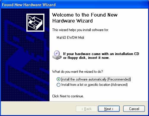
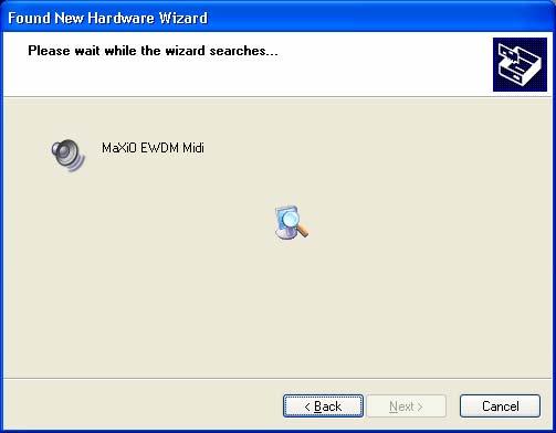
19 4. Driver Installation After completing the hardware installation of your, you need to install its driver. The installation steps in Windows 2000 and Windows XP vary, but they are similar between the different versions of Windows. The installation steps shown below are based on Windows XP installation.! CAUTION Depending on your system, you may need your Windows installation CD. Because of the driver characteristic, the driver installs several devices. In some cases Windows continuously tries to reboot your system. Unless the driver installation is completely finished, e.g. the system does not detect any new devices, DO NOT reboot the system. Restart your computer only after the drivers for all devices are installed. Follow the following steps for the installation: 1. Turn on the main power of your computer. Windows will automatically detect that a new device has been installed and prompt you with the Found New Hardware Wizard screen. Choose Install from a list or specific location and click Next >. 2. Choose Search for the best driver in these locations and specify the location of the driver. Insert the provided driver CD into the CD-ROM drive and select Include this location in the search and click Browse to find the accurate location of the driver. Then confirm your selection with Next >. 19


20 3. During installation, you will be prompted with a message warning that the driver software has not passed Windows Logo testing. Select Continue Anyway and proceed with the installation. The driver is completely tested and verified by ESI, and safe to use. 4. The EWDM Controller driver will be installed. 20
 are installed now after each other.")
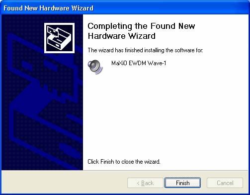
21 5. Keep going to install follow the instructions on screen. Other devices (such as EWDM Wave-1) are installed now after each other. Check the screen shots for reference. 21
22 22
23 23
24 When the system asks you to restart the computer (which happens on some computers), just ignore the requests and continue to install. When all the necessary device drivers are installed and the system is not asking you to install any further drivers, restart the computer manually. 6. Now you can check if the installation was successful. 24

25 After you restart Windows, please confirm if the task bar. icon is visible in the system tray of the Then go to My computer -> Control panel -> System -> Device Manager. Check the devices under Sound, video and game controllers, if they are installed correctly. 25

26 5. Control Panel After you completed the hardware and driver installation for your XD system, you need to learn about the Control Panel. This control panel allows you to control your setup for XD. After successfully installing the XD hardware and driver, you can see the system tray of the task bar. Clicking on this icon will launch the Control Panel. icon on the 5.1 Pull Down Menu The Control Panel includes a pull down menu section that contains the configuration menus for the XD system. File - Exit This will close the Control Panel window but it will not shut down the control panel. You can always relaunch the control panel by clicking ESI icon on the system tray. Config Mouse Wheel Controls the increment at which the volume is adjusted when using a mouse wheel. The adjustment step is from 1 to 8. 26
 to 2048 samples (48 milliseconds with 44.1 khz). Secondly there are the ultra latency settings: buffer sizes from 96 Samples (2,5 milliseconds) to 32 Samples (0.75 milliseconds).")
27 Config Latency Here you can choose between different buffer sizes. There are 2 different sections: First buffer sizes from 128 samples (3 milliseconds with 44.1 khz) to 2048 samples (48 milliseconds with 44.1 khz). Secondly there are the ultra latency settings: buffer sizes from 96 Samples (2,5 milliseconds) to 32 Samples (0.75 milliseconds). A lower latency is achieved by selecting a smaller buffer size. Typically a lower latency is good when working with software synthesizers or when you process audio signals from the audio inputs in realtime with your audio software. A smaller latency value will however also cause more system load. For most recording applications on a typical PC, select buffer sizes between 64 and 512. For a typical faster Pentium 4 system, 128 or 256 are good values. Buffer sizes of 32, 48, 1024 and 2048 are normally used only in special circumstances, e.g. 32 is reserved for very fast and reliable ASIO driver working environments only. The factory default is 512 to provide a basic level of compatibility to different systems. Config Factory Default Returns all Control Panel configuration settings to the factory default. Config - Always On Top Enables to display the Control Panel always over other windows. If this is not selected, the active windows of other applications will be shown over the Control Panel. 5.2 Input Section Port Selection E.D.I Device Detection Input Level Meter MME Channel Mapper M.D.I Analog Input M.D.I S/PDIF Input Input Monitor Buttons The left section of the control panel windows shows the status and the control features for the input channels. The main part of the display is the Input Level Meter for each channel. Above that the Control Panel displays automatically if an external device such as the EX8000 is connected to one of the E.D.I ports. Below the level meter, controls for each specific channel are provided (MME device selection for recording, M.D.I input channel selection). A detailed explanation for each section starting from top follows. Note that the input monitoring section is explained under Master Section. 27
28 Port Selection The 32 input channels of the XD system are grouped into 4 sections (ports) with 8 input channels each. For each group of 8 channels (each port), you can select either the corresponding E.D.I input (1 to 4) or the signals from the M.D.I connector by clicking on the IN PORTx label. When you change the selection of a port, the same change will be made for the output channels. When a port is set to M.D.I, the corresponding input channels from a device connected to the M.D.I port like the 032 breakout box are use. The specific E.D.I port cannot be used at the same time. For example, if you select M.D.I for port 2 (channels 9-16), you can use input channels 9-16 from device like the 032 connected to the M.D.I port of the PCI host card but you cannot use the E.D.I port 2 (e.g. if an EX8000 is connected to it). E.D.I Device Detection The Control Panel will automatically detect any device connected to a E.D.I port. For example, if EX8000 is connected to E.D.I port 1, you can control its features by double clicking on the blue EX8000 text. A separate window will be opened. MME Channel Mapper The XD system driver provides the MME device Stereo Wave (SPDIF/PCM) that can be used for recording and playback of stereo signals. The MME Channel Mapper section in the Control Panel allows you to assign the I/O channels that will be used by this MME device. You have two options to select the I/O channel for the MME device. You can click on the arrow button ( ) and then select the channel in the menu that will appear or you can click on the individual icon ( ) under each channel. The MME Channel Mapper has no influence on the multichannel MME device Multi Wave or on the ASIO driver ASIO M.D.I Analog and S/PDIF Input The PCI host card provides support for two analog input channels and a digital S/PDIF input made available via a device connected to the M.D.I port of the card. For example, the 032 breakout box provides both analog input channels and a digital S/PDIF input. The M.D.I breakout cable that is supplied with the basic XD system provides a digital S/PDIF input but no analog input channels. The two analog input channels and the two input channels from the digital S/PDIF input can be assigned to any channel pair of the 32 input channels provided by the PCI host card. The button assigns the two analog input channels to the specific channel pair, the button assigns the two S/PDIF input channels instead. Alternatively you can assign the channels via the arrow buttons ( ) on the left side and the menu that will appear when you click on it. 28
29 Please note that when you select the analog or S/PDIF input channels, the input signals from that specific channel pair from the E.D.I or M.D.I multichannel ports are no longer used. Please keep in mind that the M.D.I analog and S/PDIF input selection buttons should not be used if you do not want to use the S/PDIF or analog input signals from the device or cable connected to the M.D.I port use them only when you are using the M.D.I breakout cable (S/PDIF inputs, no analog inputs) or a M.D.I extension like the 032 breakout box (both S/PDIF and analog inputs) Input signal path block diagram E.D.I Connector #1 E.D.I Connector #2 E.D.I 1 E.D.I 2 M.D.I Connector M.D.I [1/4] 1/2 3/4 5/6 7/8 IN PORT1 8 ch. audio stream IN PORT2 M.D.I [2/4] M.D.I [3/4] M.D.I [4/4] S/PDIF IN ANALOG IN S X X A X X S A S S A A Onboard S/PDIF Input Ch. selection (CH3/4) Onboard Analog Input Ch. selection (CH1/2) same structure as port 1 Mono MIX X X REC DMA 1/2/3/4/5/6/7/8 ch. REC DMA 9/10/11/12/13/14/15/16 ch. Total 32ch DMA at (max.) 192kHz Monitor ON To PC X X Monitor OFF 1/2 3/4 5/6 7/8 9/10 11/12 13/14 15/16 Internal 64ch 32bit Digital Mixer MASTER OUT To Selected output Channel, analog out and S/PDIF out IN PORT3 IN PORT4 OUT PORT 1 OUT PORT 2 OUT PORT 3 OUT PORT 4 29

30 5.3 Output Section Port Selection E.D.I Device Detection Master Output Select Master Fader Output Level Meter MME Channel Mapper M.D.I Analog Output M.D.I S/PDIF Output Output Monitor Buttons Master to Analog & S/PDIF Button The right section of the control panel windows shows the status and the control features for the output channels. The layout is very similar to the input section (described in the previous section). The main part of the display is the Output Level Meter for each channel. Above that the Control Panel displays automatically if an external device such as the EX8000 is connected to one of the E.D.I ports. Below the level meter, controls for each specific channel are provided (MME device selection for playback, M.D.I output channel selection). A detailed explanation for each section starting from top follows. Port Selection The 32 output channels of the XD system are grouped into 4 sections (ports) with 8 output channels each. For each group of 8 channels (each port), you can select either the corresponding E.D.I output (1 to 4) or the channels of the M.D.I port by clicking on the OUT PORTx label. When you change the selection of a port, the same change will be made for the input channels. E.D.I Device Detection The Control Panel will automatically detect any device connected to a E.D.I port. For example, if EX8000 is connected to E.D.I port 1, you can control its features by double clicking on the blue EX8000 text. A separate window will be opened. MME Channel Mapper The XD system driver provides the MME device Stereo Wave (SPDIF/PCM) that can be used for recording and playback of stereo signals. The MME Channel Mapper section in the Control Panel allows you to assign the I/O channels that will be used by this MME device. You have two options to select the I/O channel for the MME device. You can click on the arrow button ( ) and then select the channel in the menu that will appear or you can click on the individual icon ( ) under each channel. The MME Channel Mapper has no influence on the multichannel MME device Multi Wave or on the ASIO driver ASIO M.D.I Analog and S/PDIF Output The PCI host card provides support for two analog output channels and a digital S/PDIF output made available via a device connected to the M.D.I port of the card. For example, the 30
31 032 breakout box provides two analog output channels and a digital S/PDIF output. The M.D.I breakout cable that is supplied with the basic XD system provides a digital S/PDIF output but no analog output channels. One channel pair each can be assigned to these analog outputs and to that S/PDIF output. The button assigns the specific channel pair to the analog output channels, the button assigns the the channel pair to the S/PDIF output. Alternatively you can assign the channels via the arrow buttons ( ) on the left side and the menu that will appear when you click on it. Please keep in mind that you can use these outputs only when you are using the M.D.I breakout cable (S/PDIF output, no analog outputs) or a M.D.I extension like the 032 breakout box (both S/PDIF and analog outputs) Master Section The Master Fader allows you to change the level of one final stereo mixed output signal. The level can be set using the mouse, mouse wheel, or cursor keys. You can select the output channel for the master signal by clicking on the red arrow left of the MASTER label. Under it, the current selection will be displayed. The picture below shows channel 1/2 of Port 3 as selection. This output receives a mix of the 8 input channels from Port 1 and the 8 playback channels from Port 2 (check the description of the monitoring buttons in the next section for reference). On this picture, the Control Panel is also configured to send out the master signal to the S/PDIF and Analog outputs of the device / cable connected to the M.D.I port. In many typical setups you would use output 1/2 of the first port (e.g. the first EX8000) as master output. Via the monitoring buttons (see below) you can then mix all signals to this stereo output. Monitoring Buttons With the monitoring buttons under each channel (input and playback), you can enable monitoring of the specific channel pair via the master output channel. : Monitoring disabled : Monitoring enabled 31
32 : Monitoring enabled, signal will be mixed to mono With the circle on the right, you can disable/enable monitoring for all input (or playback) channels simultaneously Master & Output signal path block diagram E.D.I Connector #1 E.D.I 1 E.D.I Connector #2 E.D.I 2 OUT PORT1 OUT PORT2 M.D.I Connector 1/2 ` 3/4 5/6 7/8 8 ch. audio stream same structure as port 1 M.D.I [1/4] M.D.I [2/4] M.D.I [3/4] X X Master Output Ch. selection (CH1/2) M.D.I [4/4] S/PDIF OUT S S S S S Onboard S/PDIF Output Ch. selection (CH5/6) ANALOG OUT A A A A A Onboard Analog Output Ch. selection (CH7/8) Mono MIX PLAY DMA 1/2/3/4/5/6/7/8 ch. PLAY DMA 9/10/11/12/13/14/15/16 ch. Total 32ch DMA at (max.) 192kHz Monitor ON From PC X X Monitor OFF 1/2 3/4 5/6 7/8 9/10 11/12 13/14 15/16 Internal 64ch 32bit Digital Mixer MASTER OUT 5.4 display section The display section on the right of the Control Panel window is the location where you can check and control the current status of the PCI host card. It is divided into different sections that you can call by clicking on the specific button. 32

33 5.4.1 State This panel shows you the -currently active- most important settings of the PCI host card System Clock Internal: selects the internal clock generator on the PCI host card to provide the system clock for the complete XD system. You need to use this setting when is used alone or if all other digital devices connected to the XD system are configured as clock slave. Select AUTO if you want the sample rate selected automatically (e.g. it will be controlled by the audio applications using the driver to playback or record audio). The red color shows that AUTO is on. If the automatic mode is not selected (no red color), you can select the sample rate manually. Please always set your PCI host card to internal clock before you start to change the clock settings of other digital devices. E.D.I-x: Selects the clock provided by the unit connected to the specific E.D.I port (e.g. an EX8000). This mode can only be selected when the external device (e.g. EX8000) has been configured to internal clock first (before you change this setting). S/PDIF: Selects the S/PDIF input of the PCI host card (via the M.D.I connection, e.g. the M.D.I breakout cable) as master clock. This mode can only be selected when the device connected to the S/PDIF input is configured as clock master. EXT CLK: Selects the Word Clock input of the PCI host card (via the M.D.I connection, e.g. the M.D.I breakout cable) as master clock. This mode can only be selected when the device connected to the Word Clock input is configured as clock master. You can choose between FS (Word Clock) or 256FS (Super Clock) settings. 33
34 5.4.3 I/O Config Analog: This where you adjust the analog output level of the analog output channel of the PCI host card. This analog output is only available when you have connected a device to the M.D.I port with analog outputs (such as the 032 breakout box). S/PDIF: this can be Pro, which means that actually an AES/EBU signal with the professional status bit set is transferred via the S/PDIF I/O of the PCI host card (via the M.D.I connection, e.g. the M.D.I breakout cable), or it can be Consumer, which means that normal S/PDIF signals are transferred. Word: this setting allows you to define if you want to send out a standard Word Clock (FS) or a Super Clock (256FS) signal via the Word Clock output of the M.D.I connection, e.g. the M.D.I breakout cable. 34
35 CH. Limit: The CH. Limit setting allows you to limit the maximum number of channels that are transferred via the PCI bus. If you select 32Ch, all 32 input and 32 output channels are active at the same time. If you select 16Ch, only the first 16 input and the first 16 output channels are active, if you select 8Ch, the first 8 input and the first 8 output channels are active. The lower the setting will be, the lower the PCI transfer generated by the PCI host card will be. depending on the system performance of the mainboard (and chipset) you use, you need to lower this setting from 32Ch to 16Ch or 8Ch. Only fast and modern mainboards (check the system requirements) allow you to use the 32Ch mode. the performance you can achieve with your PCI host card based system also depends on other components in your system beside the mainboard (and chipset). For example, other PCI devices in your system (like high end network adapters, SCSI controllers, SATA/RAID controllers, etc.) may affect the performance, especially when you use the 32Ch mode and higher sample rates. as a general rule, it is better to use the 8Ch mode if you do not use more than 8 input and 8 output channels or the 16Ch mode if you do not use more than 16 input and 16 output channels. as a second general rule, the sample rate you use also affects the system performance, e.g. using 192kHz requires a faster system than using 48kHz. Another example: using 192kHz at the 8Ch setting affects the system in the same way as using 48kHz at the 32Ch setting or using 96kHz at the 16Ch setting. The default setting is 8Ch. If you connect multiple external units such as EX8000 or a single 032 breakout box to one PCI host card, you need to change the CH. Limit setting before you can use more than 8 input and 8 output channels. please always check our website ( for updated information about system performance and system compatibility. If you are in doubt if your system works properly with a XD system, contact our technical support. 35


36 5.5 The EX8000 control panel Each EX8000 connected to the PCI host card has its own control panel windows that you can access by double clicking on its name in the Control Panel. Clock Setting: Defines the system clock of the specific EX8000 unit. Internal: Use the internal clock inside EX8000. EDI: Use the clock from the PCI host card (recommended default). DIGITAL 1~4: Use the clock from the digital inputs of EX
 - Mode 2 (continuous display with level meter peak hold) - Mode 3 (shows a dot representation of the level) - Mode 4 (the level meter will hold the maximum level that was reached) Routing")
37 ETC Setting ADAT S/MUX Mode: - Normal (44 khz,48 khz 8 channels) - SMUX 1 (96 khz 4 channels) - SMUX 2 (192 khz 2 channels) LED Display: - Mode 1 (shows a continuous graphical representation of the level) - Mode 2 (continuous display with level meter peak hold) - Mode 3 (shows a dot representation of the level) - Mode 4 (the level meter will hold the maximum level that was reached) Routing Table: This is where you can route input ports and output ports of EX8000. The 4 pair of stereo channels look alike and function identically. EX8000 has 4 different types of I/O ports E.D.I, Digital (AES/EBU and S/PDIF), Analog and ADAT. You can select an input port for each output port. Example: If you want to send the signal that comes from analog input to E.D.I output (to the PCI host card), you would set the control panel like shown on the following picture. Please have a look at the following audio routing table that shows you all the audio routing options of EX8000 when connected to the PCI host card. E.D.I IN 8CH 24-bit/192kHz E.D.I DIGITAL ANALOG ADAT E.D.I OUT 8CH 24-bit/192kHz DIGITAL IN 4 XLR In 4 RCA In Professional Consumer E.D.I DIGITAL ANALOG ADAT E.D.I DIGITAL OUT Professional Consumer 4 XLR Out 4 RCA Out ANALOG IN 8 XLR / TRS IN MIC / LINE, GAIN ADC E.D.I DIGITAL ANALOG ADAT E.D.I ANALOG OUT DAC 8 XLR balanced OUT 8 TRS balanced OUT ADAT OPTICAL IN Normal : 8CH 24-bit/48kHz S/MUX 2 : 4CH 24-bit/96kHz S/MUX 4 : 2CH 24-bit/192kHz E.D.I DIGITAL ANALOG ADAT E.D.I ADAT OPTICAL OUT Normal : 8CH 24-bit/48kHz S/MUX 2 : 4CH 24-bit/96kHz S/MUX 4 : 2CH 24-bit/192kHz 37
 connection is made. If Lock is displayed, an S/PDIF (or AES/EBU) signal is detected at the specific input. If Unlock is displayed, no signal is detected.")
 port. This would allow you to process an AES/EBU signal coming in on an unbalanced S/PDIF cable.")
38 Digital Audio Input Port Select: This is where you can switch between the coaxial S/PDIF digital input and the XLR AES/EBU digital input for each of the 4 digital inputs available in each format. PLL status: Shows if an S/PDIF (or AES/EBU) connection is made. If Lock is displayed, an S/PDIF (or AES/EBU) signal is detected at the specific input. If Unlock is displayed, no signal is detected. Format: - Professional (IEC 958 Type 1): EX8000 digital in/out format is AES/EBU. - Consumer (IEC 958 Type II): EX8000 digital in/out format is S/PDIF. Note that you can set this to Professional but keep the RCA (S/PDIF) port. This would allow you to process an AES/EBU signal coming in on an unbalanced S/PDIF cable. Analog Output Level Control: This is where you can control the analog output level for each playback / output channel. 38

39 6. Applications Setup This chapter contains basic configuration examples for some popular software applications. Please also refer to the manual of the audio software you use for detailed information. 6.1 Windows Multimedia setup The Windows Multimedia setup is required if you want to use your system as the main sound device for Windows multimedia applications. Go to My computer-> Control panel -> Sounds and Audio Device Properties -> Audio. Select the driver as your playback device. You can choose Multi Wave (as multichannel device for consumer audio applications supporting multichannel playback like DVD player applications) or Stereo Wave(SPDIF/PCM) (as classical stereo playback device). 39

40 6.2 Cubase and Nuendo After launching Cubase or Nuendo, go to Device -> Device Setup -> VST Multitrack. Select ASIO 2.0 as ASIO device. Then go to Default MIDI Ports and select MIDI. Note: clicking the ASIO Control Panel button will not do anything here. Make sure you click the Apply button after changing the settings. 40

, first, change the Driver Mode to ASIO on the Advanced tab of as shown below. Then restart SONAR.")
41 6.3 Cakewalk SONAR There are few steps to configure SONAR, which supports either WDM or ASIO drivers. After launching SONAR, go to Options > Audio. If you prefer the WDM/KS mode, change the settings as shown in the following picture: Note that the input and output drivers have to match each other. Restart SONAR after the settings have changed. If you prefer the ASIO mode (which is supported in SONAR 2.2 and newer), first, change the Driver Mode to ASIO on the Advanced tab of as shown below. Then restart SONAR. Note that we recommend using ASIO instead of WDM/KS as the performance will be better. 41
42 Then change all the settings as shown on the following picture: Note: enabling SONAR s software input monitoring may introduce feedback loops. You MUST disable / mute input monitoring before using SONAR s software input monitoring. 42
 or ASIO 2.0.")
43 6.4 Wavelab After launching Wavelab, go to Options -> Preference -> Audio Card. Select either MME-WDM Stereo Wave(SPDIF/PCM) or ASIO 2.0. MME configuration ASIO configuration 43

44 6.5 Tracktion The XD system comes bundled with the full version of Tracktion a professional recording and MIDI production software by Mackie / Raw Material Software. After launching Tracktion, select Settings then go to the audio devices tab. Choose ASIO as playback and record device as shown below. 44

45 7. DirectWIRE What is DirectWIRE? DirectWIRE is a 100% purely digital wire! DirectWIRE is a driver technology, developed by ESI, which can be used for routing audio streams internally within applications using EWDM Audio MIDI Drivers. With the DirectWIRE router, an application can record from other application s audio outputs without external wiring or any loss of data when they are running at the same time. DirectWIRE also allows you to easily rip any audio stream in real time by transferring data thru DirectWIRE from MP3s, live On-line Broadcast and On-demand content, and more. 7.2 DirectWIRE Panel Click on DirectWIRE on the control panel. The DirectWIRE panel window as shown below will appear. DirectWIRE digital virtual wiring technology, developed by ESI, routes audio streams internally within applications using standard audio drivers such as WDM, ASIO and MME, even when they are running at the same time. 45

46 The number on the row represents the input or output port. The columns represent ins and outs (on and off) of the respected drivers. Patch the virtual cables from one point to another as you drag the mouse. INPUT section is a new feature of DirectWIRE 3.0. It is used to route signals from 's hardware inputs. MME section represents general application's I/O: Ex.) WinAmp, WaveLab (non ASIO mode), Cakewalk, Audition, Vegas, etc. WDM section represents Multi-MME application s I/O: Ex.) SONAR (when using WDM/KS), PowerDVD, WinDVD, etc. ASIO section represents ASIO application s I/O: Ex.) Cubase, Logic, Reason, Nuendo, SONAR (when using ASIO), Samplitude, etc. GSIF section represents GSIF application like GigaStudio. Note: some applications support multiple driver modes. 7.3 DirectWIRE examples Example 1. Recording from WinAmp(MME) to WaveLab(MME): Note: If you want to record what's played back in WinAmp, but don't want to hear the sound, you should click the OUT button in the MME section so it'll change to OFF ( ). 46
47 Example 2. Recording from WinAmp(MME) to SONAR(WDM): Example 3. Recording from WinAmp(MME) to Cubase, Logic, Nuendo(ASIO): Example 4. Recording from GigaStudio(GSIF) to SONAR(WDM): 47
 to Cubase(ASIO): Example")

48 Example 5. Recording from GigaStudio(GSIF) to Cubase(ASIO): Example 6. Let's say you want to quickly dub some vocal over an audio track. It's very simple with DirectWIRE 3.0, you just have to make connections similar to these: 48
49 8. Technical Specifications PCI host card General PCI Interface Audio System Clock Support MIDI I/O WORD Clock I/O Digital Audio Coaxial (S/PDIF) ADAT E.D.I M.D.I 32bit, PCI Bus-Mastering support PCI slot compatibility designed to suit +3.3V and/or +5V PCI slot Total 32-in / 32-out, 24bit, audio interface Full Duplex - Simultaneous Record / Playback Internal (44.1, 48.0, 88.2, 96.0, 176.4, khz), Word clock, Digital In, E.D.I 1-in / 1-out 16 MIDI channel, Standard MIDI 5-pin DIN FS / 256*FS, BNC Connector Connector Impedance Format Sample rate Connector Format Sample rate Connector / Cable Format Sample rate Connector / Cable Format Sample rate RCA (Coaxial) I/O XLR : 110ohm, RCA : 75ohm IEC Professional / Consumer 44.1, 48.0, 88.2, 96.0, 176.4, khz TOS-Link (Optical) I/O ADAT protocol 44.1, 48.0kHz (8channel) 88.2, 96.0kHz (4channel - SMUX ) 176.4, 192.0kHz (2channel - SMUX ) IEEE1394 compatible E.D.I protocol ( 8-in / 8-out audio stream & control) 44.1, 48.0, 88.2, 96.0, 176.4, khz SCSI compatible / Exclusive M.D.I Cable 4 X E.D.I (32-in / 32-out audio stream) & MIDI 44.1, 48.0, 88.2, 96.0, 176.4, khz 49
50 EX8000 General Type Audio System Clock Support WORD Clock IN Power Weight Dimensions Analog Inputs Type Level Gain Range Frequency Response THD + N Dynamic Range CMRR Impedance A/D Converter Microphone Pre-amp Type Level Gain Range Equivalent Input Noise THD + N Dynamic Range CMRR Impedance 19" rack mounted, digital audio interface Total 8-in / 8-out, 24bit, audio interface Internal (44.1, 48.0, 88.2, 96.0, 176.4, khz), Word Clock, Digital In, E.D.I FS / 256*FS, BNC Connector AC IN 100V ~ 240V, 50Hz ~ 60Hz, 30W 3.5kg 482(mm) x 180(mm) x 86(mm) Balanced 1/4 TRS (Balanced XLR ) Input +4dBu Nominal (@-16.2dBFS), +20.2dBu max 0.0dB (@Gain min, +20.2dBu max) ~ +29.0dB (@Gain max, -7.8dBu max) 20Hz to 20kHz, +/- 0.1dB % A-weighted (@ -3dBFS) 116dB A-weighted 75dB 10K ohm (1/4 TRS), Low impedance : 3K ohm (XLR) Type Dynamic Range S/(N+D) Ratio Frequency Response Interchannel Isolation Gain Mismatch 24bit, 192KHz, 128X Oversampling 123dB (@ -60dBFS with A-Weighted) 110dB (@ -1dBFS, measurement method) 6.5 ~ KHz, +/ dB (@ fs=48khz) 6.5 ~ KHz, +/ dB (@ fs=96khz) 6.5 ~ KHz, +/ dB (@ fs=192khz) 123dB 0.1dB Balanced XLR (+48V Phantom Power support) 500 mv max (-3.8dBu) +25.0dB (@Gain min, -3.8dBu) ~ +73dB (@Gain max, -51.8dBu) dBu (@ 0 ohm, 20Hz ~ 20kHz) % A-weighted (@ gain+35db) 103dB A-weighted (@ gain +35dB) 90dB 1.5K ohm Analog outputs Type Level Frequency Response Analog Filter THD + N Dynamic Range Impedance D/A Converter Digital Audio AES/EBU, Coaxial (S/PDIF) ADAT E.D.I +4dBu Balanced XLR output -10dBv Balanced/Unbalanced 1/4 TRS output +4dBu Nominal (@-16dBFS), +20.0dBu max -10dBu Nominal (@-16dBFS), +8.2dBu max 20Hz to 20kHz, +/- 0.05dB 3-pole low-pass filter % A-weighted (@ -3dBFS) 118dB A-weighted 110 ohm (1/4 TRS), 110 ohm (XLR) Type Dynamic Range S/(N+D) Ratio Frequency Response Interchannel Isolation Gain Mismatch Connector Impedance Format Sample rate Connector Format Sample rate Connector Format Sample rate 24bit, 192KHz, 128X Oversampling, 8 times digital filter 120dB (@ -60dBFS with A-Weighted) 100dB (@ -1dBFS, measurement method) 0 ~ 21.7KHz, +/ dB (@ fs=48khz) 0 ~ 43.5KHz, +/ dB (@ fs=96khz) 0 ~ 87.0KHz, +/ dB (@ fs=192khz) 120dB 0.15dB XLR (AES/EBU), RCA (S/PDIF) I/O XLR : 110ohm, RCA : 75ohm IEC Professional / Consumer 44.1, 48.0, 88.2, 96.0, 176.4, khz TOS-Link (Optical) I/O ADAT protocol 44.1, 48.0kHz (8channel) 88.2, 96.0kHz (4channel - SMUX ) 176.4, 192.0kHz (2channel - SMUX ) IEEE1394 compatible E.D.I protocol 44.1, 48.0, 88.2, 96.0, 176.4, khz (8 channel) 50
51 032 breakout box General Type Audio System Clock Support MIDI I/O WORD Clock I/O Half rack type, M.D.I Based Digital audio interface Total 32-in / 32-out, 24bit, audio interface Internal (44.1, 48.0, 88.2, 96.0, 176.4, khz), Word Clock, Digital In, E.D.I 1-in / 1-out 16 MIDI channel, Standard MIDI 5-pin DIN FS / 256*FS, BNC Connector Power M.D.I Cable Power Weight 1,035g Dimensions 216(mm) x 160(mm) x 44(mm) Analog Inputs Type Level Gain Range Frequency Response THD + N Dynamic Range CMRR Impedance A/D Converter Microphone Pre-amp Type Level Gain Range Equivalent Input Noise THD + N Dynamic Range CMRR Impedance Balanced 1/4 TRS (Balanced XLR ) Input +4dBu Nominal (@-16.2dBFS), +20.2dBu max 0.0dB (@Gain min, +20.2dBu max) ~ +29.0dB (@Gain max, -7.8dBu max) 20Hz to 20kHz, +/- 0.1dB % A-weighted (@ -3dBFS) 116dB A-weighted 75dB 10K ohm (1/4 TRS), Low impedance : 3K ohm (XLR) Type Dynamic Range S/(N+D) Ratio Frequency Response Interchannel Isolation Gain Mismatch 24bit, 192KHz, 128X Oversampling 123dB (@ -60dBFS with A-Weighted) 110dB (@ -1dBFS, measurement method) 6.5 ~ KHz, +/ dB (@ fs=48khz) 6.5 ~ KHz, +/ dB (@ fs=96khz) 6.5 ~ KHz, +/ dB (@ fs=192khz) 123dB 0.1dB Balanced XLR (+48V Phantom Power support) 500 mv max (-3.8dBu) +25.0dB (@Gain min, -3.8dBu) ~ +73dB (@Gain max, -51.8dBu) dBu (@ 0 ohm, 20Hz ~ 20kHz) % A-weighted (@ gain+35db) 103dB A-weighted (@ gain +35dB) 90dB 1.5K ohm Analog outputs Type Level Frequency Response Analog Filter THD + N Dynamic Range Impedance D/A Converter Digital Audio Coaxial (S/PDIF) ADAT +4dBu Balanced XLR output -10dBv Balanced/Unbalanced 1/4 TRS output +4dBu Nominal (@-16dBFS), +20.0dBu max -10dBu Nominal (@-16dBFS), +8.2dBu max 20Hz to 20kHz, +/- 0.05dB 3-pole low-pass filter % A-weighted (@ -3dBFS) 118dB A-weighted 110 ohm (1/4 TRS), 110 ohm (XLR) Type Dynamic Range S/(N+D) Ratio Frequency Response Interchannel Isolation Gain Mismatch Connector Impedance Format Sample rate Connector Format Sample rate 24bit, 192KHz, 128X Oversampling, 8 times digital filter 120dB (@ -60dBFS with A-Weighted) 100dB (@ -1dBFS, measurement method) 0 ~ 21.7KHz, +/ dB (@ fs=48khz) 0 ~ 43.5KHz, +/ dB (@ fs=96khz) 0 ~ 87.0KHz, +/ dB (@ fs=192khz) 120dB 0.15dB RCA (S/PDIF) I/O RCA : 75ohm IEC Professional / Consumer 44.1, 48.0, 88.2, 96.0, 176.4, khz TOS-Link (Optical) I/O ADAT protocol 44.1, 48.0kHz (8channel) 88.2, 96.0kHz (4channel - SMUX ) 176.4, 192.0kHz (2channel - SMUX ) 51
4-in/6-out USB Recording Interface. User s Guide
 4-in/6-out USB Recording Interface User s Guide - Copyright 2007 Revision 1, June 2007 www.esi-audio.com INDEX 1. Introduction... 4 1.1 What s in the box... 4 1.2 Key Features... 4 2. Description of U46
High Quality 4-in / 4-out PCIe Audio Interface. User s Guide
 High Quality 4-in / 4-out PCIe Audio Interface User s Guide - Copyright 2008 Revision 1, December 2008 www.esi-audio.com INDEX 1. Introduction... 4 2. Description of... 4 2.1 PCIe card connectors... 4
High Quality 24-bit 192kHz 4x4 reference audio interface with swappable I/O socket. User s Guide
 High Quality 24-bit 192kHz 4x4 reference audio interface with swappable I/O socket User s Guide - Copyright 2004, 2005, 2006 Revision 5, November 2006 www.esi-audio.com INDEX 1. Introduction... 5 Key Features...
24-bit USB Audio Interface with S/PDIF I/O. User s Guide
 24-bit USB Audio Interface with S/PDIF I/O User s Guide - Copyright 2008-2018 Revision 5, June 2018 www.esi-audio.com INDEX 1. Introduction... 4 1.1 Key Features... 4 2. Description of... 4 2.1 Front Panel...
Waveterminal 192M INDEX. 1. Introduction to Waveterminal 192M Description of Waveterminal 192M Break out box 6. 2.
 INDEX 1. Introduction to 4 2. Description of 6 1. Break out box 6 2. PCI card 6 3. Hardware Installation 8 1. System Requirement 8 2. Preparation for hardware installation 9 3. Installing PCI card 10 4.
18-in/8-out USB 2.0 Hi-Speed External Recording Interface. User s Guide
 18-in/8-out USB 2.0 Hi-Speed External Recording Interface User s Guide - Copyright 2007 Revision 1, November 2007 www.esi-audio.com INDEX 1. Introduction... 4 1.1 What s in the box... 4 1.2 Key Features...
Professional 24-bit USB Audio Interface. User s Guide
 Professional 24-bit USB Audio Interface User s Guide - Copyright 2016-2017 Revision 2, May 2017 www.esi-audio.com INDEX 1. Introduction... 4 1.1 Features... 4 2. Installation... 7 2.1 System Recommendation...
7. 22 END USER WARRANTY V.1
 INDEX 1. Introduction... 2 1.1. What s in the box... 2 1.2. Key Features... 3 2. Description of U46DJ... 4 2.1. Front Panel... 4 2.2. Rear Panel... 5 2.3. Connection with external devices... 6 3. Hardware
The Hard Disk Sampler Tool Kit! GIGAStation. Owner s Manual.
 The Hard Disk Sampler Tool Kit! GIGAStation Owner s Manual www.egosys.net All rights to this document are reserved. No part of this document may be copied reproduced, or distributed in any form or by any
 The FCC Regulation Warning This equipment has been tested and found to comply with the limits for a Class A digital device, pursuant to Part 15 of the FCC Rules and CISPR pursuant to subchapter EN55022
WARRANTY. EGO SYStems Inc. warrants the return policy to its original purchaser as follows; All EGO SYS products,
 WARRANTY EGO SYStems Inc. warrants the return policy to its original purchaser as follows; All EGO SYS products, under normal use, will be free from faulty as long as the purchaser owns this product. The
1 Mic-In / 1 Guitar-In, 2-Out Professional vocal recording USB Interface. User manual
 1 Mic-In / 1 Guitar-In, 2-Out Professional vocal recording USB Interface User manual Important Safety Instructions 1. Read this manual thoroughly before using this unit. 2. Keep this manual for future
5.1.5 Digital Mixer Outputs Physical Outputs Sample Clock Generator Sample Clock Sources
 Contents 1 Introduction...5 1.1 Overview...5 1.2 Features...6 1.3 Before you begin...6 1.4 In the box...7 1.5 System requirements...7 1.5.1 Windows...7 1.5.2 Macintosh...7 1.6 Nomenclature used in this
INDEX. * All specifications are subject to change without prior notice. v2 November 2005
 INDEX 1. Introduction... 2 Key Features... 2 2. Description of M8U... 3 Front Panel... 3 3. System Requirements... 5 PC... 5 Mac... 5 4. Installation... 6 Hardware Installation... 6 Driver Installation
OVERVIEW SYSTEM REQUIREMENTS
 USER GUIDE OVERVIEW The AI-1 USB Audio Interface adds studio-quality Input and Output capabilities to your PC or Mac, turning your recording software into a full recording setup. With its high quality
GAMBIT DAC2 FIREWIRE DAC OPERATING MANUAL
 GAMBIT DAC2 FIREWIRE DAC OPERATING MANUAL Daniel Weiss Engineering Ltd., Florastr. 42, CH-8610 Uster Page 1 of 7 Congratulations on purchasing the Weiss Gambit Series DAC2 D/A Converter! The DAC2 is a
Summary Product Contents Specifications System Requirements Product Photography. Sound Blaster Audigy 2 ZS Platinum Pro
 Recording and production excellence for the home-studio. The is the ultimate 7.1 studio solution for musicians and audio enthusiasts. It supports ASIO 2.0 and SoundFont 2.1 and can record up to 6 simultaneous
USB AUDIO INTERFACE. Steinberg Web Site C.S.G., Pro Audio Division 2012 Yamaha Corporation 209MW-A0
 USB AUDIO INTERFACE EN DE FR ES IT ZH JA Steinberg Web Site http://www.steinberg.net C.S.G., Pro Audio Division 2012 Yamaha Corporation 209MW-A0 Contents Contents Contents...2 A Message From the Development
FIREWORKS. POWER: Supports external and FireWire bus power
 FIREWORKS FireWire Audio Interface Module FIREWIRE FEATURES: Two 1394a 400 megabit ports Texas Instruments icelynx with integrated phy, link, and ARM7 processor Multiple channels at up to 19 khz: 1in /
Pentium-class computer with one available PCI slot Windows 7 / Vista / 2003 / XP / 2000, (32/64 bit) DirectX 8.1 above is required
 DirectX 8.1 above is required") MANUAL DN-33700 Features Full-duplex playback and recording Full-duplex 8CH DAC/2CH ADC Support 48/44.1 KHz sampling rate for playback and recording Supports the latest Dolby Digital EX and DTS ES 6.1/7.1
MANUAL DN-33700 Features Full-duplex playback and recording Full-duplex 8CH DAC/2CH ADC Support 48/44.1 KHz sampling rate for playback and recording Supports the latest Dolby Digital EX and DTS ES 6.1/7.1
TOA ELECTRIC CO., LTD.
 Operating Instruction Manual TOA MIXING CONSOLE Model RX-31C TOA ELECTRIC CO., LTD. KOBE, JAPAN Contents General Description...2 Features...2 Front Panel...3 Rear Panel...4 Rack Mounting Instructions...5
MANUAL. Delta Table of Contents
 AUDIO TM Delta 1010 MANUAL Version D1010-092999 Table of Contents Introduction................................................................................... 2 What s in the Box..............................................................................
Introduction. 3. What s in the Box?. 3. About the ProFire 2626 FireWire Audio Interface. 4. ProFire 2626 Features. 5. System Requirements.
 User Guide User Guide Introduction. 3 What s in the Box?. 3 About the ProFire 2626 FireWire Audio Interface. 4 ProFire 2626 Features. 5 System Requirements. 6 Minimum System Requirements/Specifications.
S a l e s G u i d e E-MU 0204 USB 1
 Sales Guide E-MU 0204 USB 1 E-MU 0204 USB HIGH-RESOLUTION USB POWERED AUDIO INTERFACE Retail Street Price: US = $129.99 UK = 129.99 (including new 20% VAT from Jan. 1, 2010) Euro = 129.99 (including 20%
1 Mic-In / 2-Out Professional Vocal Recording USB Interface. User manual
 1 Mic-In / 2-Out Professional Vocal Recording USB Interface User manual Important Safety Instructions 1. Read this manual thoroughly before using this unit. 2. Keep this manual for future reference. 3.
Reference Manual Roland Corporation 01
 Reference Manual 2017 Roland Corporation 01 Panel Descriptions Rubix22 Front Panel 1 2 3 2 1 6 7 8 When connecting a guitar or bass, use the INPUT 1L jack. The sound level will be very low if you connect
Overview. Features. Technical Data Sheet 1 / 6. Mixing Console AG03
 Overview AG03 is a multi-purpose mixer with USB audio interface, especially optimized for webcasting. Rear Panel Features Input channels: 3 Line Inputs (1 mono, 1 stereo), 1 Mic Inputs with 48V phantom
Overview. Features. Technical Data Sheet 1 / 6. Mixing Console AG06
 Overview AG6 is a multi-purpose mixer with USB audio interface, especially optimized for webcasting. Rear Panel Features Input channels: 6 Line Inputs (2 mono, 2 stereo), 2 Mic Inputs with 48V phantom
PXR 1506 / WATT MIXER AMPLIFIER
 PXR 1506 / 1508 150-WATT MIXER AMPLIFIER Operating Manual www.peavey.com ENGLISH PXR 1506 / 1508 150-Watt, 8-Channel Mixer Amplifier Designed with the latest Peavey technology, the PXR 1506 / 1508 powered
Quick Start Guide. Quick Start Guide - 0
 Quick Start Guide 0404 Quick Start Guide - 0 1- Introduction Creative Professional Thank you for purchasing the E-MU 0404 Digital Audio System. We ve designed this E-MU Product to be logical, intuitive
MARC 2. User s Guide
 MARC 2 User s Guide The Marc 2 conforms the following standards: EN 55022: 1998 + A1: 2000 + A2: 2003; class A EN 55024: 1998 + A1: 2000 + A2: 2003; class A In order for an installation of this product
3. Suggested Use and Configurations Multiple Computers with a Single DiGiGrid M... 11
 D Table of Contents Introduction...4 1. GETTING STARTED...5 1.1 System Requirements...5 1.2 Registration...5 1.3 Software Installation...5 1.4 Licenses...6 2. Hardware...7 3. Suggested Use and Configurations...8
Introduction. What s in the Box? About the Delta 44 Digital Recording Interface
 Delta 44 Table of Contents Introduction................................................2 What s in the Box?...........................................2 About the Delta 44 Digital Recording............................2
QUICKSTART GUIDE ENGLISH ( 3 9 ) MANUAL DE INICIO RÁPIDO ESPAÑOL ( ) GUIDE D UTILISATION RAPIDE FRANÇAIS ( )
 MANUAL DE INICIO RÁPIDO ESPAÑOL ( ) GUIDE D UTILISATION RAPIDE FRANÇAIS ( )") QUICKSTART GUIDE ENGLISH ( 3 ) MANUAL DE INICIO RÁPIDO ESPAÑOL ( 11 17 ) GUIDE D UTILISATION RAPIDE FRANÇAIS ( 1 25 ) MANUALE RAPIDO DI UTILIZZAZIONE ITALIANO ( 27 33 ) KURZANLEITUNG DEUTSCH ( 35 41 )
QUICKSTART GUIDE ENGLISH ( 3 ) MANUAL DE INICIO RÁPIDO ESPAÑOL ( 11 17 ) GUIDE D UTILISATION RAPIDE FRANÇAIS ( 1 25 ) MANUALE RAPIDO DI UTILIZZAZIONE ITALIANO ( 27 33 ) KURZANLEITUNG DEUTSCH ( 35 41 )
LINEAR PCI AUDIO ADAPTER
 MAY-2004 REV-B LINEAR PCI AUDIO ADAPTER DESCRIPTION The is a professional PCI audio adapter designed for use in radio broadcast production. The adapter offers two stereo record stream from either a balanced
Overview. Features. Technical Data Sheet 1 / 6. Digital Mixer TF-RACK
 Overview The intuitive TouchFlow Operation interface is optimized for touchpanel control and provides an easy-to-use digital mixing console environment for a broad spectrum of users and uses. The TF-RACK
Delta 44 Manual. Table of Contents
 Delta 44 Manual version: D66-021502 Table of Contents Introduction................................................2 What s in the Box?...........................................2 About the Delta 66 Digital
E3360 First Edition August Xonar D2X. Audio Card. Quick Installation Guide
 E3360 First Edition August 2007 Xonar D2X Audio Card Quick Installation Guide 1.1 Installation requirements To ensure a successful installation of the Xonar D2X audio card, your computer must meet the
Matrix K. User's Manual. Version 1.0
 Matrix K User's Manual Version 1.0 FCC INFORMATION (U.S.A) 1. IMPORTANT NOTICE: DO NOT MODIFY THIS UNIT! This product, when installed as indicated in the instructions contained in this manual, meets FCC
Apogee Quartet. QuickStart Guide
 Apogee Quartet QuickStart Guide V1, September, 2012 Contents Overview! 3 Introduction! 3 Package contents! 4 Quartet panel tour! 5 Display and touchpad tour! 7 Connecting to your Mac! 8 Adjusting Input
Overview. Features. Technical Data Sheet 1 / 6. Digital Mixing Console TF1
 Overview The intuitive TouchFlow Operation interface is optimized for touchpanel control and provides an easy-to-use digital mixing console environment for a broad spectrum of users and uses. The TF1 Digital
Firefly 302. Portable FireWire Unit
 Portable FireWire Unit IMPORTANT SAFETY INSTRUCTIONS The apparatus shall not be exposed to dripping or splashing and that no objects with liquids, such as vases, shall be placed on the apparatus. The MAINS
Check the contents of the package
 Read this first! UA-4FX Owner s Manual Copyright 2005 ROLAND CORPORATION All rights reserved. No part of this publication may be reproduced in any form without the written permission of ROLAND CORPORATION.
LoLa280. Professional multichannel sound card. User manual
 Professional multichannel sound card For technical support, please contact your supplier Digigram S.A. 82/84 Allée Galilée, 38330 Montbonnot-Saint-Martin, FRANCE Tel: +33 (0)4 76 52 47 47 Fax: +33 (0)
4-In / 2-Out with +48V Phantom Power Recording USB Interface. User manual
 4-In / 2-Out with +48V Phantom Power Recording USB Interface User manual Important Safety Instructions 1. Read this manual thoroughly before using this unit. 2. Keep this manual for future reference. 3.
DESCRIPTION FEATURES MULTISTREAM PCI SOUND CARDS 26 DECEMBER 2007 ASI6514, ASI6518
 26 DECEMBER 2007 ASI6514, ASI6518 MULTISTREAM PCI SOUND CARDS DESCRIPTION The ASI6514 and ASI6518 are professional PCI sound cards designed for use in radio broadcast automation. Providing up to 16 play
Overview. Features. Technical Data Sheet 1 / 6. Mixing Console MG10. MG10 is a versatile mixer suitable for a wide range of users and applications.
 Overview MG10 is a versatile mixer suitable for a wide range of users and applications. Rear Panel Features Input channels: 10 Line Inputs (4 mono, 3 stereo), 4 Mic Inputs with 48V phantom power and HPH
3. Suggested Uses And Configurations Adding More I/Os to Your System Multiple Computers with a Single DiGiGrid Q...
 Table of Contents Introduction...4 1. Getting Started...5 1.1 System Requirements...5 1.2 Registration...5 1.3 Software Installation...5 1.4 Licenses...6 2. HARDWARE...7 2.1 Monitoring options...8 3. Suggested
PCX924e PCX924e-Mic PCX22e
 PCX94e PCX94e-Mic PCXe Professional Stereo Sound Cards For technical support, please contact your system supplier Digigram S.A. 8/84 Allée Galilée, 80 Montbonnot-Saint-Martin, FRANCE Tel: + (0)4 76 5 47
MANUAL DELTA 66. Table of Contents
 AUDIO TM DELTA 66 MANUAL Table of Contents Introduction.................................................. 2 What s in the Box?............................................. 2 About the Delta 66 Digital
1 master and 8 independent stereo subgroup Flexible architecture including a modular control surface, outputs
 Digital Audio Console OXF-R3 High-end digital recording and mix-down console 24 cue/auxiliary send buses, which can be linked for Provides exemplary sound quality and greater functionality stereo than
D i g i g r a m. VX222HR VX222HR-Mic. Professional Stereo Sound Cards. User s manual
 VX222HR VX222HR-Mic Professional Stereo Sound Cards User s manual For technical support, please contact your system supplier Digigram S.A. Parc de Pré Milliet, 38330 Montbonnot - FRANCE Tel: +33 (0)4 76
END USER WARRANTY. For technical support inquiries, contact your nearest dealer or visit online technical support at
 END USER WARRANTY EGO SYSTEMS, INC. warrants the return policy to its original purchaser as follows: All EGO SYSTEMS INC. s products, under normal use, will be free from fault as long as the purchaser
Ref. No " DUAL CD PLAYER, MIXER AND CASE USER MANUAL
 Ref. No. 170.408 19" DUAL CD PLAYER, MIXER AND CASE USER MANUAL 1 CAUTION RISK OF ELECTRIC SHOCK DO NOT OPEN To prevent electric shock, do not remove top or bottom covers. No user serviceable parts inside.
Owner s Manual.
 Owner s Manual PMX402M PMX602M PMX802M 4 CHANNELS 6 CHANNELS 8 CHANNELS www.pyleaudio.com FEATURES Rugged and easy to operate, PMX402m/602m/802m offers great features and performance at an extremely affordable
Digital Audio Systems Desktop Sampling Systems
 Digital Audio Systems Desktop Sampling Systems Digital Audio Systems E-MU s new Digital Audio Systems deliver everything you need to produce audio on a PC with professional results 24-bit/192kHz converters,
MG12XU Overview Features Technical Data Sheet
 Overview MG12XU is a versatile mixer suitable for a wide range of users and applications. Rear Panel Features Input channels: 12 Line Inputs (4 mono, 4 stereo), 6 Mic Inputs with 48V phantom power and
Fast Track C600 User Guide
 Fast Track C600 User Guide Legal Notices This guide is copyrighted 2011 by Avid Technology, Inc., with all rights reserved. Under copyright laws, this guide may not be duplicated in whole or in part without
Aardvark USA 202 East Washington Suite 306 Ann Arbor, Michigan Web:
 Aardvark USA 202 East Washington Suite 306 Ann Arbor, Michigan 48104 Web: http://www.aardvark-pro.com E-mail: info@aardvark-pro.com Voice: 734-665-8899 Fax: 734-665-0694 Q10 OWNERS MANUAL TABLE OF CONTENTS
Direct Pro LX6 Specifications, Options, & Components
 Direct Pro LX6 Specifications, Options, & Components O W N E R Direct Pro LX6 Specifications: Converters: THD+N: Dynamic Range: Frequency Response: Sample Rates: Analog Inputs: Analog Outputs: Headphone
D i g i g r a m. VX222v2. Professional Stereo Sound Card. User s manual
 Professional Stereo Sound Card User s manual For technical support, please contact your local distributor. list available at www.digigram.com 2 Digigram S.A. Parc de Pré Milliet, 38330 Montbonnot - FRANCE
MOTU 2408mk3 Overview
 MOTU.com - MOTU 2408mk3 Overview http://www.motu.com/products/pciaudio/2408 1 of 1 8/11/2008 1:46 PM MOTU 2408mk3 Overview This bo contains everything you need to turn your computer into a powerful 24-bit/96kHz
UA-2X2 audio interface. user manual
 UA-2X2 audio interface user manual Musikhaus Thomann Thomann GmbH Hans-Thomann-Straße 1 96138 Burgebrach Germany Telephone: +49 (0) 9546 9223-0 E-mail: info@thomann.de Internet: www.thomann.de 20.06.2018,
USB Audio MIDI Interface with Mic Pre/Mixer REFERENCE MANUAL
 D01268420C US-20x20 USB Audio MIDI Interface with Mic Pre/Mixer REFERENCE MANUAL Before connecting this unit to a computer, you must download and install dedicated software on the computer. Contents 1
INSTRUCTIONS FOR USE Pro-Ject Pre Box RS digital
 INSTRUCTIONS FOR USE Pro-Ject Pre Box RS digital Dear music lover, thank you for purchasing this Pro-Ject Audio Systems preamplifier. In order to achieve maximum performance and reliability you should
LapTop. LapTop LAYLA. 24 LAYLA LapTop MONA MONA GINA 24 MIA. Owner s Manual Version 3.0 for Windows
 LAYLA 24 LAYLA LapTop LapTop MONA MONA LapTop GINA 24 MIA Owner s Manual Version 3.0 for Windows Designed and Manufactured in the U.S. by Echo Corporation Important Safety Instructions 1. Read Instructions
a22xt artesia artesia Virgin Musical Instrument Company Inc Owners Manual professional audio interface for musicians on t~e go
 a22xt professional audio interface for musicians on te go Owners Manual artesia Virgin Musical Instrument Company Inc r POBox 2908 La Mesa CA 91943 PH: 888-999-9848 E-mail: info@virginmusicalinstruments.com
HDACC High Def Audio Control Center
 HDACC High Def Audio Control Center Operation Manual Contact: Bob Rapoport, bob@essenceelectrostatic.com, 727-580-4393 St. Petersburg, FL USA SAFETY PRECAUTIONS Please read all instructions before attempting
USER GUIDE 1 of 26 STAGEGRID 4000 User Guide rev.01 abr-18
 USER GUIDE 1 of 26 STAGEGRID 4000 User Guide rev.01 abr-18 SUMÁRIO About... 2 STAGEGRID 4000... 2 SoundGrid... 3 System Requirements... 3 Hardware... 4 Package Contents... 4 Rack Installation... 5 Setups...
USB 3.0. Operation Manual 2015 ZOOM CORPORATION. Copying or reprinting this manual in part or in whole without permission is prohibited.
 USB 3.0 Operation Manual 2015 ZOOM CORPORATION Copying or reprinting this manual in part or in whole without permission is prohibited. Contents/Introduction Contents Introduction... 02 Usage and Safety
Firefly 808 FIREWIRE INTERFACE
 Firefly 808 FIREWIRE INTERFACE IMPORTANT SAFETY INSTRUCTIONS The apparatus shall not be exposed to dripping or splashing and that no objects with liquids, such as vases, shall be placed on the apparatus.
IN 2 USB 2.0 COMPUTER AUDIO INTERFACE OWNER S MANUAL
 IN 2 USB 2.0 COMPUTER AUDIO INTERFACE OWNER S MANUAL IN2 Safety Declarations CAUTION: For protection against electric shock, do not remove the cover. No user serviceable parts inside. WARNING: This equipment
SL Interpreter Compact
 SL Interpreter Compact Interpreter Console FEATURES stand-alone console, no need for external equipment individual volume and tone controls for 2 interpreters built-in distribution amplifier allows easy
Getting Started with Digi 001
 Getting Started with Digi 001 Version 5.1 for Macintosh and Windows 98/Me Digidesign Inc. 3401-A Hillview Avenue Palo Alto, CA 94304 USA tel: 650 842 7900 fax: 650 842 7999 Technical Support (USA) 650
MADI-PC MADI RECORDING SYSTEM
 MADI-PC MADI RECORDING SYSTEM USER MANUAL V1.0 1 P a g e Table of Contents INTRODUCTION... 3 IMPORTANT SAFETLY PRECAUTIONS... 4 General Safety... 4 Caution... 4 Power Safety... 5 Installation Notes...
Introducing the SoundWave 7.1 PCI. The SoundWave 7.1 PCI transforms your PC into a home theater system with multi-channel surround sound.
 SoundWave 7.1 PCI Quick Installation Guide Introducing the SoundWave 7.1 PCI The SoundWave 7.1 PCI transforms your PC into a home theater system with multi-channel surround sound. Features Compliant with
USBPre 2. User Guide and Technical Information
 USBPre 2 User Guide and Technical Information Sound Devices, LLC 300 Wengel Drive Reedsburg, WI USA +1 (608) 524-0625 fax: +1 (608) 524-0655 Toll-Free: (800) 505-0625 www.sounddevices.com support@sounddevices.com
Quick Guide. You must read the Usage and Safety Precautions before use.
 Quick Guide You must read the Usage and Safety Precautions before use. The Operation Manual can be downloaded from the ZOOM website (https://www.zoom.jp/docs/l-0). 018 ZOOM CORPORATION Copying or reprinting
PMX402M 4 CHANNELS PMX602M 6 CHANNELS PMX802M 8 CHANNELS
 Owner s Manual PMX402M 4 CHANNELS PMX602M 6 CHANNELS PMX802M 8 CHANNELS www.pyleaudio.com FEATURES Balanced microphone inputs, high impedance microphone/line Inputs and Tape/CD inputs. All may be used
PCX1221HR PCX1222HR. Professional Multichannel Sound Cards. User manual
 PCXHR PCXHR Professional Multichannel Sound Cards User manual For technical support, please contact your system supplier Digigram S.A. 8/84 Allée Galilée, 80 Montbonnot-Saint-Martin, FRANCE Tel: (0)4 76
EASY FIREWIRE Audio Interface
 EASY FIREWIRE Audio Interface ENGLISH USER S MANUAL IMPORTANT SAFETY INSTRUCTIONS shall be placed on the apparatus. The MAINS plug is used as the disconnect device, the disconnect device shall remain readily
DS-DAC-100 DS-DAC-100m DS-DAC-10
 DS-DAC-100 DS-DAC-100m DS-DAC-10 Owner's Manual Advanced Guide Before you connect this device You must select driver settings in order to use the DS-DAC-100, DS-DAC-100m, or DS- DAC-10. To ensure that
SYNAPSE. High Channel Density Networked Audio Interfaces AES67. Common Features DM 1. D32 o. D32 i. Product Family Overview. Applications.
 High Channel Density Networked Audio Interfaces Product Family Overview Product The Synapse product family adds high performance, high channel density analog and digital audio connectivity, monitoring
Mastering Analog to Digital / Digital to Analog Converter. User Manual Including October 2012 Version 5 Firmware and Feature Update
 Mastering Analog to Digital / Digital to Analog Converter User Manual Including October 2012 Version 5 Firmware and Feature Update Lynx Studio Technology, Inc. www.lynxstudio.com support@lynxstudio.com
Copyright. Warning. Warning! Communications & Safety Regulation Information
 96i I/O Copyright 2006 Digidesign, a division of Avid Technology, Inc. All rights reserved. This guide may not be duplicated in whole or in part without the express written consent of Digidesign. Avid,
AMP20. User Manual.
 AMP20 User Manual www.audac.eu 2 Index Introduction 5 Precautions 6 Safety requirements 6 Caution servicing 7 EC Declaration of Conformity 7 Waste of Electrical and Electronic Equipment (WEEE) 7 Chapter
User's manual Studio 22 Pro USB
 User's manual Studio 22 Pro USB Precaution Thank you for purchasing this digital appliance. To ensure perfect operation and security, please read the manual carefully and retain it for future reference.
DL32R. 32-Channel Wireless Digital Live Sound Mixer with ipad Control
 DLR Sound Mixer with ipad Control FEATURES: -Channel wireless digital mixer Onyx recallable mic pres with wireless control 14 fully-assignable XLR outputs Stereo AES digital output Total recall of all
HDx TDM Record/Playback Option Guide
 HDx TDM Record/Playback Option Guide Version 1.0 for D-Show Digidesign 2001 Junipero Serra Boulevard Daly City, CA 94014-3886 USA tel: 650 731 6300 fax: 650 731 6399 Technical Support (USA) tel: 650 731
D User Manual Of D200 DSD 32bit 384KHZ DAC. USB input 384K volume dB. D *140mm.
 32 --- User Manual Of DSD 32bit 384KHZ DAC USB input 384K volume - 18.5dB For a better experience with this product, please read this manual carefully before using it, and keep it for future reference.
Sono 61. English User Guide
 Sono 61 English User Guide 1 Introduction.............................................................. 3 ProKeys Sono 61 Features............................................... 4 What s in the Box?.......................................................
2 Mic/1-Guitar in, 2 Line out recording USB Interface. User manual
 2 Mic/1-Guitar in, 2 Line out recording USB Interface User manual Important Safety Instructions 1. Read this manual thoroughly before using this unit. 2. Keep this manual for future reference. 3. Take
T L Audio INDIGO SERIES. User Manual PA-2001 VALVE PRE-AMPLIFIER. Tony Larking Professional Sales Limited, Letchworth, England.
 T L Audio INDIGO SERIES User Manual PA-2001 VALVE PRE-AMPLIFIER Tony Larking Professional Sales Limited, Letchworth, England. Tel: 01462 490600. International +44 1462 490600. Fax: 01462 490700. International
DA-3700 Digital Karaoke Mixing Amplifier with Key Control
 DA-3700 MIC 1 MIC 2 ECHO ST MONO VOL LOW HIGH REPEAT DELAY -15 +15 0 10-15 +15 0 10 0 10 Digital Karaoke Mixing Amplifier with Key Control OWNER S MANUAL ST MONO VOL LOW HIGH 0 10-15 +15-15 +15 REPEAT
SoundWave Pro PCI Quick Installation Guide
 SoundWave Pro PCI Quick Installation Guide Introducing the SoundWave Pro PCI The SoundWave Pro PCI provides 3D sound effects and supports DirectSound 3D TM, MPU-401, GM and is fully compatible with Sound
PCX1221e PCX1222e. Professional Multichannel Sound Cards. User manual
 PCX11e PCX1e Professional Multichannel Sound Cards User manual For technical support, please contact your system supplier Digigram S.A. 8/84 Allée Galilée, 80 Montbonnot-Saint-Martin, FRANCE Tel: + (0)4
LapTop. LapTop LAYLA. 24 LAYLA LapTop MONA MONA GINA 24 MIA. Owner s Manual Version 3.0 for Macintosh
 LAYLA 24 LAYLA LapTop LapTop MONA MONA LapTop GINA 24 MIA Owner s Manual Version 3.0 for Macintosh Designed and Manufactured in the U.S. by Echo Corporation Important Safety Instructions 1. Read Instructions
3. Suggested Uses And Configurations Adding More I/Os to Your System Multiple Computers with a Single DiGiGrid IOX...
 Table of Contents Introduction...4 1. Getting Started...5 1.1 System Requirements...5 1.2 Registration...5 1.3 Software Installation...6 1.4 Licenses...6 2. HARDWARE...7 3. Suggested Uses And Configurations...9
Apogee Symphony I/O Mk II
 Apogee Symphony I/O Mk II User s Guide April 2017 Contents Overview... 5 Introduction... 5 Features... 5 Package Contents... 6 Register your product : apogeedigital.com/register... 6 Symphony I/O Mk II
LAYLA. 24 LAYLA LapTop GINA 24 MIA MIAMIDI. Owner s Manual Version 3.1 for Windows
 LAYLA 24 LAYLA LapTop GINA 24 MIA MIAMIDI Owner s Manual Version 3.1 for Windows Important Safety Instructions 1. Read Instructions - Be sure to read all of the safety and operating instructions before