212iL Rev. 1.1
|
|
|
- Victor Strickland
- 5 years ago
- Views:
Transcription
1 212iL 1
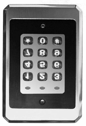
 Keypad Single Unit Keypad- Control Installation Manual Features: 120 User Capability Illuminated Backlit Hardened Keys")

2 International Electronics, Inc. 427 Turnpike Street Canton, Massachusetts iL (illuminated Luxury) Keypad Single Unit Keypad- Control Installation Manual Features: 120 User Capability Illuminated Backlit Hardened Keys Programmable Second Relay Activation Time Remote Trigger Input (REX) Heavy Traffic Application Flush Mount Indoor Applications Installation: Section 1: Unpacking and checking the packing list Section 2: Mounting the 212iL Section 3: Wiring the 212iL Section 4: Power Up Section 5: Programming the 212iL Section 6: Troubleshooting Section 1: Unpacking and checking the packing list Open the box, and inside you will find: 1 212iL keypad 1 6 Wire conductor harness 2 1 1/4" black, socket cap flat head machine screws 2 1 1/4" black, Phillips flat head sheet metal screws 1 11/64" Allen wrench 1 Installation Manual for 212iL Please check the contents of this package and verify all components in the packing list are present. Taking this inventory will familiarize you with the components as well as ensure that you have a complete parts list. Section 2: Mounting the 212iL (212iL Dimensions: 3 3/8" x 5 1/8" x 5/8") 1. Select the appropriate location for the 212iL. Mounting height is the same for an electrical switch, 48" on center. Be sure that the 212iL is mounted indoors ONLY! 48" 2

3 The 212iL should be mounted to a standard single gang electrical box (with the small slot in the trim ring facing down), but it also is able to mount directly to a flat indoor surface with the provided mounting screws. Section 3: Wiring Electrical Specifications: Operating Voltages: VDC only on input voltage. Maximum Current allowed voltages: 140mA. Temperature Tolerance: Standard, -20 to 130 F. 1. Attach the 6-conductor wire harness to the plug in connector on the back of the 212iL. 2. Next you will need to attach the relay wires (white/yellow, blue, and brown) to the wire run that is connected to the locking device. Brown (N/O) Wire Blue (Common) Wire White/Yellow (N/C) Wire White/Black (REX) Wire Black (Negative) Wire Input Red (Positive) Wire Input Wiring to a Magnetic Lock: (see below) If you are sharing the same DC voltage power supply with the 212iL and the magnetic lock, (that is to say if you have only one power supply for both the 212iL and the lock device), you need to run voltage through the common (Blue) wire on the 6 conductor wire harness of the 212iL. The reason is that the 212iL is equipped with a Form C, Dry contact relay on board. This means that there is no voltage running through the relay. (Until you supply the common leg of the relay with voltage). Step 1: Splice together the Blue Relay Common wire from the 212iL harness to the Red wire on the 212iL harness. (Positive voltage coming from the power supply.) Step 2: Connect the White /Yellow wire (Normally Closed) from the 212iL harness to the Positive connection on the Magnetic lock. Step 3: Splice together the Black Negative voltage wire on the 212iL harness (negative voltage coming from the power supply) to the Negative connection on the Magnetic lock. Blue (C) Wire White/Yellow (N/C) Wire Magnetic Lock (Fail Safe) V- V- Wiring to an Electric Strike: (see below) If you are sharing the same DC voltage power supply with the 212iL and the Electric Strike, (that is to say if you have only one power supply for both the 212iL and the lock device), you need to run voltage through the common (Blue) wire on the 6 conductor wire harness of the 212iL. The reason is that 3

4 the 212iL is equipped with a Form C, Dry contact relay on board. This means that there is no voltage running through the relay. (Until you supply the common leg of the relay with voltage). Step 1: Splice together the Blue Relay Common wire from the 212iL harness to the Red wire on the 212iL harness. (Positive voltage coming from the power supply.) Step 2: Connect the Brown (Normally Open) wire from the 212iL harness to the Positive voltage connection on the Electric door strike. Step 3: Splice together the Black Negative voltage wire on the 212iL harness (negative voltage coming from the power supply) to the Negative connection on the Electric door strike. Blue (C) Wire Electric Strike (Fail Secure) Brown (N/O) Wire V- V- Shunting a Normally Closed Zone: (see below) Step 1: Connect the Blue (Common) Relay wire from the 212iL harness to the Common connection on the door position switch. Step 2: Connect the Brown (Normally Open) Relay wire from the 212iL harness to the Normally closed connection on the Door position switch. Brown (N/O) Wire To Alarm Panel V- Normally Closed Door Position Contacts Blue (Common) Wire To Alarm Panel 4
5 Wiring to a Request to Exit (Push to release): The 212iL keypad may be wired to monitor a remote-switching device, and is meant to be installed on the secured side of the door. This is a momentary input that will engage the main relay for the same amount of time that the master code is programmed with. This input requires a momentary closure between the White with a Black trace wire and the Black wire. The only time the REX won't follow the main relay time is if the Master code has been programmed to latch the main relay. In this case, the REX will operate with the default time of 5 seconds. You may wire in several devices parallel to release the door from different locations. There is no programming required for this option. Step 1: Connect the White with Black trace wire on the 212iL harness to the common connection on the REX device. Step 2: Splice a wire to the Black (negative) wire on the 212iL harness and connect to the Normally Open connection on the REX device. Example wiring to an IEI request to exit device (part # EZ-REX): White/Black Wire V- Black (Negative) Wire If your REX device sends voltage when it is pressed, you must connect an external relay to the wires coming from the REX, then connect the 212iL REX connections to the common and the normally open connections on the external relay. Section 4: Power Up Making the Power Connections: (The 212iL is powered with VDC ONLY) Step 1: Connect the Red (Positive voltage input) wire from the 212iL harness to the positive voltage output connection on the power supply. Step 2: Connect the Black (Negative voltage input) wire from the 212iL harness to the negative voltage output connection on the power supply. Upon power up, the 212iL will cycle through the LED's from left to right twice to indicate proper keypad operation. (If the LED's continue to flash, refer to the trouble shooting section of this manual). The Backlighting will now be on and will dim 15 seconds after the last keypress or 5 seconds after the programming mode has been exited. Perform the Self-Test by pressing 7890#123456*. The LED s will cycle from Green to Yellow to Red and then the sounder will beep three times. 5
6 Section 5: Programming the 212iL The 212iL supports 120 user codes that will operate the keypad and energize the main relay. A user code is stored in the memory of the 212iL with an individual user location, and may be 1 to 6 digits in length. Each user code has an associated user location. To help with the understanding of user locations, think of them like shelves. The 212iL has 120 shelves (user locations) in it, and each user code gets put into its own shelf (user location). For example: the Master code, factory defaulted to 1234, is always stored with user location 1. Every time a new user code is added, the user location must be advanced by one digit. To do any programming the 212iL must be put into the Programming Mode. Step 1: Entering the Programming Mode. Programming is accessed by entering the command that tells the 212iL that programming is the desired function. The command is always as follows: 99 followed by the # key. Next the current Master Code has to be entered. Then finish the command by pressing the * key. Example: 99 # 1234 * If the programming command was done successfully, the 212iL will start flashing the yellow LED slowly, indicating that it is now in the programming mode. If the yellow does not come on flashing, that is an indication that the incorrect Master code was entered. (Validate the Master code). Step 2: Changing the Master Code. The 212iL comes with the factory programmed Master code of This may be changed to any code that has 1 to 6 digits in length. The 212iL also comes set from the factory with a 5 second relay activation time that may be changed to any time from 01 to 99 seconds. The 212iL has to be in programming mode before you can change the Master code. To Change the Master code: (Yellow LED flashing slowly). Next enter user location "1" which is always the Master code s user number. Next enter in the new Master code followed by the * key (Yellow LED flashes rapidly). Repeat the new Master code followed by the * key. (Yellow LED will flash slowly). If the change was successful, the yellow LED will still be flashing. Example: 1 # 4321 * 4321 * To Change the Main Relay Activation Time: (Yellow LED flashing slowly). Next enter the relay activation time in a two digit format "08" for 8 seconds. Next enter user location "1" which is always the Master code s user number. Next enter in the Master code followed by the * key (Yellow LED flashes rapidly). Repeat the Master code followed by the * key. (Yellow LED will flash slowly). If the change was successful, the yellow LED will still be flashing. Example: 08 # 1 # 4321 * 4321 * To exit the programming mode press the * key. Or continue for more programming. 6
7 Step 3: Adding or Changing User Codes. User codes may be 1 to 6 digits in length. The 212iL has to be in programming mode to add or change users Next enter the user location. (2, 3, 4, ) Now enter the new code followed by the * key (Yellow LED flashes rapidly). Repeat the new code followed by the * key (Yellow LED will flash slowly). If the change was successful, the yellow LED will still be flashing slowly. Codes entered in this fashion will hold the relay time programmed with the master code. Example: 2 # 6789 * 6789 * 3 # 5378 * 5378 * 4 # * * To exit the programming mode press the * key. Or continue for more programming. Step 4: Creating a User Code to Latch the Main Relay. A latching user code is used when the need to have the device that is being controlled by the 212iL activate or deactivate for an indefinite amount of time. This operates much like a light switch. When you enter a latching user code, the Main relay will activate and stay activated until the same code or a like latching user code is entered to deactivate the relay. Next enter the relay time of "00" Next enter the user location. (2, 3, 4, ) Now enter the new code followed by the * key (Yellow LED flashes rapidly). Repeat the new code followed by the * key (Yellow LED will flash slowly). If the change was successful, the yellow LED will still be flashing slowly. Example: 00 # 12 # 7788 * 7788 * 00 # 55 # 6632 * 6632 * 00 # 93 # * * To exit the programming mode press the * key. Or continue for more programming Step 5: Changing the 212iL Feedback Options. The 212iL has two key-press feed back options that you may choose from. One is an audio feed back. This will activate the on board sounder every time that a key is pressed. The other is a visual feed back. This will flash the yellow LED on the front of the keypad every time that a key is pressed. These two options are used to verify that a key has been successfully pressed. Both of these options may be used together. Audio Option: Next press Command number 30 followed by the # key. Next press "0" for the audio feed back option followed by the # key. Next press "0" to Disable or "1" to Enable the audio option followed by the # key. Next press the * key (Yellow LED flashes rapidly). Next press the * key (Yellow LED will flash slowly). Example: 30 # 0 # 0 # (This will disable the sounder from activating every time a key is pressed). 7
8 Visual Option: Next press Command number 30 followed by the # key. Next press "1" for the visual feed back option followed by the # key. Next press "0" to Disable or "1" to Enable the visual option followed by the # key. Next press the * key (Yellow LED flashes rapidly). Next press the * key (Yellow LED will flash slowly). If the change was successful, the yellow LED will still be flashing slowly. Example: 30 # 1 # 0 # (This will disable the yellow led from activating every time a key is pressed). Step 6: Auto-Entry. Auto entry is used when the need for the code not to be followed by the * key is desired. The user only needs to enter their code number and the relay will activate for the programmed relay time. To use this feature, the user codes must be the same length as the Master code. The 212iL has to be in programming mode to change any option. Next press Command number 30 followed by the # key. Next press "2" for the Auto-Entry option followed by the # key. Next press "0" to Disable or "1" to Enable the Auto-Entry option followed by the # key. Next press the * key (Yellow LED flashes rapidly). Next press the * key (Yellow LED will flash slowly). If the change was successful, the yellow LED will still be flashing slowly. Example: 30 # 2 # 1 # (This will remove the * key from the code). Step 7: Reset to Factory Default. This command is used when the user numbers are not known which makes it possible to change or delete the codes. When this command has been done successfully the 212iL will be reset to the factory default settings of 1234 as the Master code and 05 seconds as the relay activation time. Next press Command number 46 followed by the # key. Next press the "0" key five times followed by the # key. Next press the "0" key five times followed by the # key. Next press the * key (Yellow LED flashes rapidly). Next press the * key (Yellow LED will flash slowly). If the change was successful, the yellow LED will still be flashing slowly. Example: 46 # # # If the Master code is not working or has been forgotten, power down the 212iL and connect the White with Black trace wire to the Red wire and power up the 212iL. This will put the 212iL into program mode indicated by the flashing yellow LED. Next enter 46#00000#00000# to default the keypad. Power down to remove the White/Black wire from the Red wire. 8
9 Programming Options Chart If the pre-programmed default values must be changed Or additional functions are desired, the following options may be programmed. 1. Enter programming mode Press 99 # (master code) * 2. Changing the master code Press 1 # (new code) * (repeat code) * 3. Change the main relay activation time NOTE 1 Press (relay time) # 1 # (master code) * (repeat code) * Example: Master code with a 8 second relay time Press (08) # 1 # 1234 * 1234 * 4. Add or change user codes NOTE 2 Press (user location) # (new code) * (repeat Code) * 5. Add a user to latch the main relay NOTE 1 Press (00) # (user location) # (new code) * (repeat code) * 6. Turn audible keypress feedback ON Press 30 # 0 # 1 # 7. Turn audible keypress feedback OFF Press 30 # 0 # 0 # 8. Turn visual keypress feedback ON Press 30 # 1 # 1 # 9. Turn visual keypress feedback OFF Press 30 # 1 # 0 # 10. Turn Auto-Entry ON Press 30 # 2 # 1 # 11. Turn Auto-Entry OFF Press 30 # 2 # 0 # 12. Erase keypad memory and reset defaults Press 46 # # # NOTES: NOTE 1. Relay time must be represented in a two-digit format. For example 5 seconds is entered as 05. Latching relay time is entered with a time of 00. NOTE 2. Codes entered in this fashion will hold the relay time that the master code is programmed with. For a detailed explanation of each option please refer to prior pages
10 Section 6: Trouble Shooting. Refer to this section if the 212iL is not responding correctly to the operation outlined in this instruction manual. The 212iL has been designed to operate with VDC only. Verify that the voltage powering this keypad is within these parameters. Situation 1: Reason: Solution: Situation 2: Reason: Solution: Situation 3: Reason: Solution: Situation 4: Reason: Solution: LED's are slowly cycling from right to left and the Backlighting is off. The 212iL has been designed to monitor for low voltage. Once the low voltage has been detected, the keypad shuts down some of its options like backlighting to ensure operation of the keypad until the problem can be attended to. Check the output voltage of the power supply with a meter to verify the output voltage rating listed for that device. If it is below the voltage threshold of 9 VDC, you must increase the voltage beyond the minimum rating of 9 VDC. LED's are rapidly cycling from left to right and the keypad has lost all operation. The 212iL has been designed to monitor for over voltage. This is a very "severe" condition and therefore significantly affects the keypad s operation. Once the over voltage has been detected, the keypad shuts down all operation and will not operate until the voltage irregularity has been corrected. Check the output voltage of the power supply with a meter to verify the output voltage rating listed for that device. If it is over the voltage threshold of 30 VDC, you must reduce the output below the threshold. The Master code is not allowing access to the programming mode. There are a few reasons that this situation could occur. The most common is that the Master code was programmed incorrectly. That is to say that someone used the incorrect user number to add a user code. The Master code is always kept in memory with user number "1". The other reason this could happen is that the code was simply forgotten. Power down the keypad, connect the white/black wire to the Red wire on the 212iL wire harness and power back up. The yellow LED will be flashing indicating that the keypad is now in programming mode. Change the Master code by press 1 # (New Master Code) * (Repeat Master Code). When finished with programming, power down the unit, separate the white/black wire from the Red wire on the 212iL harness and power back up. The keypad is now ready to use. No LED's are lit on the keypad Power is not reaching the keypad. With a meter check the voltage connection at the 212iL keypad on the Red & Black wires. Confirm that there is actually voltage at the keypad. If there is no voltage reading at the keypad, use the meter on the power supply to verify that voltage is leaving the power supply. If there is no voltage coming out of the power supply, call the manufacturer of that power supply. If there is voltage at the power supply, but not at the keypad, use the meter to test each of the wires for a break in the wire. 10

11 International Electronics Incorporated (IEI) warrants its products to be free from defects in material and workmanship, when they have been installed in accordance with the manufacturer s instructions, and have not been modified or tampered with. IEI does not assume any responsibility for damage or injury to person or property due to improper care, storage handling, abuse, misuse, normal wear and tear, or an act of God. IEI s sole responsibility is limited to the repair (at IEI s option) or the replacement of the defective product or part when sent to IEI s facility (freight and insurance charges prepaid), after obtaining IEI s Return Merchandise Authorization. IEI will not be liable to the purchaser or any one else for incidental or consequential damages arising from any defect in, or malfunction of, it s products. This warranty shall expire two years after shipping date for Door Gard Keypads. Except as stated above, IEI makes no warranties, either expressed or implied, as to any matter whatsoever, including, without limitation to, the condition of its products, their merchantability, or fitness for any particular application. INTERNATIONAL ELECTRONICS, INC. 427 Turnpike Street Canton, MA U.S.A. Phone: (781) (800) Sales in MA (800) Sales FAX: (781) Visit our Web Site at 11
232iLM Keypad Installation and Programming Instructions
 232iLM Keypad Installation and Programming Instructions Note: This product is designed to be installed and serviced by security and lock industry professionals. Specifications Case Dimensions: 6 1 / 2
Secured Series: Hub Plus Kit Single Door Controller Package Installation Manual
 Secured Series: Hub Plus Kit Single Door Controller Package Installation Manual This package is designed to simplify the connections to our Secured Series Hub Plus Controller. This will translate into
FEATURES AND PROGRAMMING GUIDE SELF-CONTAINED ACCESS CONTROL SYSTEMS:
 FEATURES AND PROGRAMMING GUIDE SELF-CONTAINED ACCESS CONTROL SYSTEMS: 233CARDREADER DOOR-GARD SELF-CONTAINED ACCESS CONTROL SYSTEMS offer field proven reliability and cost effective solutions for residential,
9212i INSTALLATION. Stand-Alone Keypad. Instructions
 INSTALLATION 9212i Stand-Alone Keypad Instructions Features: 4 Independent Outputs 4 Independent Timers All Outputs Assignable by Code On board 5 Amp Form C Relay 120 Users Remote Triggering Input Keypad
232iLM Keypad Installation & Programming Instructions
 232iLM Keypad Installation & Programming Instructions Note: This product is designed to be installed and serviced by security and lock industry professionals. Specifications Case Dimensions: 6-1/2 L x
2000 Series e/em Style Keypad Installation and Programming Manual
 2000 Series e/em Style Keypad Installation and Programming Manual Document Number: 6054022 Revision: 0 Date: 12/21/06 Table of Contents Table of Contents Section 1: Introduction... 6 1 Product Description...6
KP2000E/EM Series Style Keypad
 23852973 KP2000E/EM Series Style Keypad Installation and Programming Instructions Models KP2000EXX and KP2000EMXX Specifications Parameter Voltage Requirements Keypad Current Requirements (Max) Relay Contact
Digital Keypad Introduction
 K2 Digital Keypad Introduction The K02 uses the latest microprocessor technology to operate door strikes and security systems that require a momentary (timed) or latching dry contact closure. All programming
SK-1011-SQ Digital Access Keypad with 5A Relay Output
 User Operation for the SK--SQ. Using the User Codes: A. User codes operate the door (4-8 digits long). Press u u u u B. The key must also be pressed if the keypad is in manual-entry mode. Press u u u u
Carefree-Security. Installation and programming instructions 1050A. Owner s Manual
 Carefree-Security Heavy Duty Commercial - Industrial Fully Sealed Digital Access Keypad Specially Designed for Gate Operators, Overhead Doors, Specialty Doors & Electric Door Locking Devices SINGLE OR
MODEL KP-100 ACCESS CONTROL DIGITAL KEYPAD OPERATING INSTRUCTIONS
 MODEL KP-100 ACCESS CONTROL DIGITAL KEYPAD OPERATING INSTRUCTIONS Model KP-100 is a self-contained digital keypad. This keypad is suitable for residential, industrial, and commercial installations. It
ENFORCER SK-1131-SQ. Digital Access Keypad with 5A Relay Output MANUAL. Digital Access Keypad Manual. Also available from SECO-LARM: Outdoor Keypads
 User Operation for the SK--SQ Note: n n n nindicates. Using the User Codes: A. User codes operate the door (4-8 digits long). the inhibit code. Note: u u u uindicates Press u u u u the user code. B. The
Indoor/Outdoor Proximity Reader and Keypad with 10cm (4in) Read Range
 Read Range") Indoor/Outdoor Proximity Reader and Keypad with 10cm (4in) Read Range Stand alone CR-R885-SB Installation and Operating Instructions V1.1 TABLE OF CONTENTS Installation... 2 Mounting and Wiring... 2 Mounting
Indoor/Outdoor Proximity Reader and Keypad with 10cm (4in) Read Range Stand alone CR-R885-SB Installation and Operating Instructions V1.1 TABLE OF CONTENTS Installation... 2 Mounting and Wiring... 2 Mounting
AirTest Model CN9000 Series Sensor Controller
 AirTest Model CN9000 Series Sensor Controller AirTest Model CN9000 Series Sensor Controller THEORY OF OPERATION A basic CN9000 configuration consists of Input/Process/Display combination modules, a 3 relay
eforce 150 Keyless Entry Owner s manual & User s guide For Model 3090
 eforce 150 Keyless Entry Owner s manual & User s guide For Model 3090 This manual contains important operation, maintenance & warranty information. Save this manual for future reference TABLE OF CONTENTS
F6-Fingerprint. Access Control/Reader. User Manual. F6 - Simplified Instruction. (Master Code) # (Factory default:1234) Enter the Programming Mode
 # (Factory default:1234) Enter the Programming Mode") -Fingerprint Access Control/Reader Function Description Enter the Programming Mode - Simplified Instruction Operation (Factory default:1234) Change the Master Code Add Fingerprint User Add Card User Add
-Fingerprint Access Control/Reader Function Description Enter the Programming Mode - Simplified Instruction Operation (Factory default:1234) Change the Master Code Add Fingerprint User Add Card User Add
e-ask electronic Access Security Keyless-entry OEM / Dealer / Installer Cargo Lock / Unlock Version Installation & Instructions (UM04 ~ )
") e-ask electronic Access Security Keyless-entry OEM / Dealer / Installer Cargo Lock / Unlock Version Installation & Instructions (UM04 ~ 18990-04) Table of Contents Introduction... 1 e-fob Operation and
e-ask electronic Access Security Keyless-entry OEM / Dealer / Installer Cargo Lock / Unlock Version Installation & Instructions (UM04 ~ 18990-04) Table of Contents Introduction... 1 e-fob Operation and
User/Installation Manual
 User/Installation Manual ADVANTAGE DKLP MODEL 19-100(i) Your Partner in Access Control www.americanaccess.com AAS 2Year Limited Warranty What item(s) this warranty applies to: American Access Systems DKLP
INSTRUCTION MANUAL AC-T43 PIEZO-KEYPAD STANDALONE ACCESS CONTROL UNIT. 07/04
 INSTRUCTION MANUAL 1 2 3 4 5 6 7 8 9 0 # PIEZO-KEYPAD STANDALONE ACCESS CONTROL UNIT www.rosslaresecurity.com 0706-0960050-00 07/04 Contents INTRODUCTION 4 Technical Specifications 5 Key Features 6 INSTALLATION
INSTALLATION INSTRUCTIONS 920 EntryCheck TM
 801 Avenida Acaso, Camarillo, Ca. 93012 (805) 494-0622 www.sdcsecurity.com E-mail: service@sdcsecurity.com INSTALLATION INSTRUCTIONS 920 EntryCheck TM The EntryCheck 920 Indoor/Outdoor Keypad is a surface-mount
INSTALLATION INSTRUCTIONS 921P EntryCheck TM
 80 Avenida Acaso, Camarillo, Ca. 90 (805) 494-06 www.sdcsecurity.com E-mail: service@sdcsecurity.com INSTALLATION INSTRUCTIONS 9P EntryCheck TM The EntryCheck 9P Indoor/Outdoor Keypad is a surface mount
SK-1011-SDQ Access Control Keypad. Manual
 SK-1011-SDQ Access Control Keypad Manual Quick Installation Guide: This page is for installers looking to do a basic installation and programming of the keypad. For more in-depth installation and programming
Proximity Card and Pin Reader Installation Manual
 Multi Prox Proximity Card and Pin Reader Installation Manual PUBLICATION INFORMATION 60A9 - Draft Release Version 0.1.2 71D0 - Version 1.0.5 CONTENTS Introduction... 1 Legend... 2 Terminology... 2 Mounting...
AS Keypad User Manual
 AS Keypad User Manual Specifications Operating Voltage: 12~24 VAC/DC Current Draw: TBA Input: request-to-exit (for Relay 1) time out reed switch contact (for Relay 1) Output: Relay 1: N.O./N.C./Com. Output
INSTALLATION INSTRUCTIONS 920P EntryCheck TM
 801 Avenida Acaso, Camarillo, Ca. 93012 (805) 494-0622 www.sdcsecurity.com E-mail: service@sdcsecurity.com INSTALLATION INSTRUCTIONS 920P EntryCheck TM The EntryCheck 920P Indoor/Outdoor Keypad is a surface-mount
Plus-X 300. Installation and Operation Manual
 Plus-X 300 Installation and Operation Manual Table of Contents Introduction... 1 Compatibility... 1 Installation... 1 Configuration... 2 Operation... 5 Getting Help... 6 Warranty... 6 Appendix A: Specifications...
ENFORCER. SK-1123-SQ Outdoor Digital Access Keypad with 2 Outputs MANUAL. Digital Access Keypad Manual. Also available from SECO-LARM: Outdoor Keypads
 Quick Reference Guide. Using the User Codes: A. User codes operate the door (4-8 digits long). Press u u u u B. The key must be pressed also if the keypad is in manual-entry mode. Press u u u u Note: u
Section 1 General Description. Section 3 How to Program Keypad. Section 2 Installation. CM-120TX Wireless Digital Keypads Installation Instructions
 CM-120TX Wireless Digital Keypads Installation Instructions Package Contents - (1) Keypad and faceplate assembly - (1) Foam gasket (CM-120W only) - (2) #6-32 x 1 S/S Phillips screws - (2) #6-32 x 1 Tamperproof
Outdoor Stand-Alone Weatherproof Keypads
 Outdo Stand-Alone Weatherproof Keypads Manual (SK-2323-SDQ shown) (SK-1323-SPQ shown) Model Number 2 Relay Outputs Mullion-Style Keypads Backlit Keys Proximity Reader SK-2323-SDQ SK-2323-SPQ Sealed-Environment
AP41 / AP81 SERIES TIME SWITCHES
 FN:AP41_81M1.DOC AP41 / AP81 SERIES TIME SWITCHES AP41 AP81 TABLE OF CONTENTS INTRODUCTION 2 SPECIFICATIONS 2 INSTALLATION 5 FRONT PANEL DESCRIPTION 7 OPERATION 8 Filling out the Program Record Sheet 8
Installing Keypad and Backplate
 Installing Keypad and Backplate Fig.1 Positioning of Fixing Holes and Cable Outlet Cable Outlet, Drill Diameter 10mm for Cable Access Remove the back plate, which is fitted to rear of the keypad, using
Series 803 LED Product Price Display
 Series 803 LED Product Price Display May 2007 Rev. 1.1 1 Installation and Operation Manual Table of contents 1. Safety.......3 2. Series 803 sign features.......4 2.1 Sign descriptions........4 2.2 Control
DG Series. Access Control Proximity Readers DG-160 DG-800
 DG Series Access Control Proximity Readers DG-800 + DG-160 + Features: Applicable card modeem Card / Key Fob 1 Administrator and 200 Users 200 Proximity Cards / Key fobs Access ModesUse Bluetooth smartphone,
Bluetooth Enabled Access Control MODEL BG-FE. Operating Instructions
 BlueGuard FE Bluetooth Enabled Access Control MODEL BG-FE Operating Instructions CAUTION AND SAFETY INFORMATION IMPORTANT: If the equipment is used in a manner not specified in this manual, the protection
TDM-150 TIMER DISPLAY
 TDM-150 TIMER DISPLAY TECHNICAL MANUAL Covers TDM-150D, TDM-150F Version 1.1 August 2016 Safety Precautions Caution Read Instructions: Read and understand all safety and operating instructions before using
VANDAL RESISTANT BACK-LIT WEATHERPROOF ACCESS CONTROL KEYPAD
 VANDAL RESISTANT BACK-LIT WEATHERPROOF ACCESS CONTROL KEYPAD Post Mount Keypad Programming & Installation Manual 1. Connect Power 12V DC to 24V AC/DC to terminals (+) and (-) Post Mount Keypad Quick Start
Kodiak Mobile INTELLIGENT DOCKING STATION USERS MANUAL PART NUMBER: PANASONIC CF53 TOUGHBOOK COMPATIBLE AN ISO 9001:2008 CERTIFIED COMPANY
 CUSTOMER SERVICE If you have any questions or require additional information please contact Customer Service at 877-455-6886, Monday though Friday, 8:00am - 5:00pm CST. TECHNICAL SUPPORT Kodiak Mobile
INSTALLATION INSTRUCTIONS Model 930 EntryCheck
 SECURITY DOOR CONTROLS 3580 Willow Lane, Westlake Village, CA 91361-4921 (805) 494-0622 Fax: (805) 494-8861 www.sdcsecurity.com E-mail: service@sdcsecurity.com INSTALLATION INSTRUCTIONS Model 930 EntryCheck
E-Access ANXELL TECHNOLOGY CORPORATION E3AK4 E3AK2. Specifications Voltage (Input): 12 to 24 VDC
: 12 to 24 VDC") E-Access E3AK1 E3AK2 E3AK3 E3AK4 4-3/4" x 2-15/16" x 1-13/16" (120 x 74 x 46.2 mm ) 4-1/2" x2-3/4" x1-5/8" (114 x 70 x 41 mm) 4-13/16" x 3" x 2-1/2" (123 x 77 x 64.2 mm) 3-7/16" x 3-7/16" x 1-3/4" (87.3
E-Access E3AK1 E3AK2 E3AK3 E3AK4 4-3/4" x 2-15/16" x 1-13/16" (120 x 74 x 46.2 mm ) 4-1/2" x2-3/4" x1-5/8" (114 x 70 x 41 mm) 4-13/16" x 3" x 2-1/2" (123 x 77 x 64.2 mm) 3-7/16" x 3-7/16" x 1-3/4" (87.3
AE21 SERIES DISPLAY CONTROL TERMINAL
 FN:AE21MAN1.DOC AE21 SERIES DISPLAY CONTROL TERMINAL DESCRIPTION The AE21 Series Display Control Terminal is used for implementing various display functions. It consists of a control terminal, the AE21,
CM-500 SK 500 USER CODES KEYPAD
 CM-500 SK 500 USER CODES KEYPAD Wiring diagram PCB front view ST2 1 3 1 3 N/C contact RL1 (magnet) N/O contact RL1 (strike) ST1 3 2 1 ST2 1 3 RL2 RL1 Strike 2 1 E M B 3 5 T C O 12 V V1 PB2 PB1 Input voltage
SKE Series. 12-Pad. Installation & Instruction Manual. Essex Electronics, Inc KEY-LESS fax keyless.
 SKE Series 12-Pad Installation & Instruction Manual Essex Electronics, Inc. 805.684.7601 800.KEY-LESS fax 805.684.0232 keyless.com SKE Series 12-Pad Self-Contained Keyless Entry System With Relay All rights
Automatic Phone-Out Home Monitoring System
 Automatic Phone-Out Home Monitoring System Freeze Alarm Model Number: THP217 Product Description This product is intended to monitor homes, cabins, and other premises for low temperature conditions. It
K-PROX Series INSTALLATION & INSTRUCTION MANUAL. Essex Electronics, Inc KEY-LESS fax keyless.com
 K-PROX Series INSTALLATION & INSTRUCTION MANUAL K-Prox Series Self-Contained Keyless Entry System All rights reserved. No part of this documentation may be reproduced in any form, without prior written
CV-550SPK V2 Waterproof Keypad/Reader/Controller Installation Instructions
 CV-550SPK V2 Waterproof Keypad/Reader/Controller Installation Instructions Packing List NAME MODEL/SIZE QTY Self tapping screw 0.15 x 1.06 (4mm 27 mm) Rubber plug 0.23 x 1.2 (6mm 30 mm) Star screw driver
PAC1 Door Access Controller
 PAC1 Door Access Controller Series 1 TABLE OF CONTENTS i PAGE Introduction...1 Features...1 Specifications...2 Terminal Descriptions...3 Programmable Features Description...5 Automatic Relock Function...5
AC-Q4x Family. Instruction Manual. Vandal Resistant Stand-Alone controllers. Models: AC-Q41H/HB AC-Q41SB AC-Q42H/HB AC-Q42SB AC-Q44
 AC-Q4x Family Vandal Resistant Stand-Alone controllers Instruction Manual ls: AC-Q41H/HB AC-Q41SB AC-Q42H/HB AC-Q42SB AC-Q44 December 2006 Table of Contents Table of Contents 1. General Information...
Waterproof. Keypad/Reader/Controller
 Waterproof Keypad/Reader/Controller User Manual W1-C W3-C User manual 1. Packing List Name Quantity Remarks Digital Keypad-W1-C/W3-C 1 User manual 1 Screw driver 1 Rubber bungs 4 6*27mm, used for fixing
DP-222Q Color Video Door Phone Manual
 DP-222Q Color Video Door Phone Manual * has 6 LEDs for nighttime operation Remotely and securely talk to visitors and unlock doors, gates, etc. from the Easily connect a secondary * Simple 2-wire connection
PAC1 Door Access Controller
 PAC1 Door Access Controller Series 1 100% Designed and Manufactured by: NIDAC SECURITY PTY. LTD. 2 CROMWELL STREET BURWOOD, VICTORIA Tel: (03) 9808 6244 AUSTRALIA 3125 Fax: (03) 9808 9335 Revision 1.1
DOLXFD1000B. Waterproof Access Control/Reader
 DOLXFD1000B Waterproof Access Control/Reader INTRODUCTION The DOLXFD1000B is a single- entry multi-function Access Controller with integrated keypad and card reader. It is designed and manufactured to
A-100 INDOOR STAINLESS STEEL KEYPAD WIRING & PROGRAMMING INSTRUCTIONS
 345 Bayview Avenue Amityville, New York 11701 For Sales and Repairs 1-800-ALA-LOCK For Technical Service 1-800-645-9440 Publicly traded on NASDAQ Symbol: NSSC ALAR LOCK 2006 INDOOR STAINLESS STEEL KEYPAD
EASON TECHNOLOGY. IO8 & IO24 Break-Out Module
 EASON TECHNOLOGY IO8 & IO24 Break-Out Module p/n 50-00180-01 Revision1.2 Eason Technology, Inc. 7975 Cameron Dr. Bldg 300 Windsor, CA 95492 Phone (707) 837-0120 FAX (707) 837-2742 http://www.eason.com
e-ask electronic Access Security Keyless-entry RF Keyless-entry entry System TM-Multi Multi Installation Manual FCC ID: TV2EFOB1 (UM21 ~ )
") e-ask electronic Access Security Keyless-entry e-fob RF Keyless-entry entry System TM-Multi Multi Installation Manual FCC ID: TV2EFOB1 (UM21 ~ 22795-01) Table of Contents Introduction... 1 e-fob Operation
e-ask electronic Access Security Keyless-entry e-fob RF Keyless-entry entry System TM-Multi Multi Installation Manual FCC ID: TV2EFOB1 (UM21 ~ 22795-01) Table of Contents Introduction... 1 e-fob Operation
DP-222Q Color Video Door Phone Manual
 DP-222Q Color Video Door Phone Manual * has 6 LEDs for nighttime operation Remotely and securely talk to visitors and unlock doors, gates, etc. from the Easily connect an secondary * Simple 2-wire connection
Compact Keypad. ins /02/2010. Exit button (push to make) 12V DC release current rating must be less than 1A.
 12V DC release current rating must be less than 1A.") Compact Keypad Grey Exit button (push to make) 1V DC White Black 115V DC (fuse rating 1A) 1V DC release current rating must be less than 1A. The diode current rating must be equal to or greater than the
Compact Keypad Grey Exit button (push to make) 1V DC White Black 115V DC (fuse rating 1A) 1V DC release current rating must be less than 1A. The diode current rating must be equal to or greater than the
INSTRUCTION MANUAL FN-8118 SCAN HERE
 FENIEX // 2018 // INSTRUCTION MANUAL Is this the latest version? SCAN HERE FN-8118 INSTRUCTION MANUAL Feniex Product Copyrights This price List and the mentioned Feniex products include or describe copyrighted
AC-115 Compact Networked Single-Door Controller Hardware Installation and Programming
 AC-115 Compact Networked Single- Controller Hardware Installation and Programming Copyright 2013 by Rosslare. All rights reserved. This manual and the information contained herein are proprietary to REL,
4300 WINDFERN RD #100 - HOUSTON TX VOICE (713) FAX (713) web: IMPORTANT!!!
 FAX (713) web: IMPORTANT!!!") 4300 WINDFERN RD #100 - HOUSTON TX 77041-8943 VOICE (713) 973-6905 - FAX (713) 973-9352 web: www.twrlighting.com IMPORTANT!!! PLEASE TAKE THE TIME TO FILL OUT THIS FORM COMPLETELY. FILE IT IN A SAFE PLACE.
4300 WINDFERN RD #100 - HOUSTON TX 77041-8943 VOICE (713) 973-6905 - FAX (713) 973-9352 web: www.twrlighting.com IMPORTANT!!! PLEASE TAKE THE TIME TO FILL OUT THIS FORM COMPLETELY. FILE IT IN A SAFE PLACE.
I/O Expansion Box Installation & Operator s Instruction Manual
 I/O Expansion Box Installation & Operator s Instruction Manual May 2004 CTB Inc. Warranty I/O Expansion Box CTB Inc. Warranty CTB Inc. warrants each new Chore-Tronics product manufactured by it to be free
AK-21. Digital Keyless Entry System. Installation and Programming Instructions
 AK-2 Digital Keyless Entry System Installation and Programming Instructions (760) 8-7000 USA & Canada (800) 2-587 & (800) 92-02 Toll Free FAX (800) 68-0 www.linearcorp.com CONTENTS COMPONENT LOCATIONS.......................................
4300 WINDFERN RD #100 HOUSTON TX VOICE (713) FAX (713) web: IMPORTANT!!!
 FAX (713) web: IMPORTANT!!!") 4300 WINDFERN RD #100 HOUSTON TX 77041-8943 VOICE (713) 973-6905 FAX (713) 973-9352 web: www.twrlighting.com IMPORTANT!!! PLEASE TAKE THE TIME TO FILL OUT THIS FORM COMPLETELY. FILE IT IN A SAFE PLACE.
4300 WINDFERN RD #100 HOUSTON TX 77041-8943 VOICE (713) 973-6905 FAX (713) 973-9352 web: www.twrlighting.com IMPORTANT!!! PLEASE TAKE THE TIME TO FILL OUT THIS FORM COMPLETELY. FILE IT IN A SAFE PLACE.
Single Door Standalone Access Control User Manual
 Single Door Standalone Access Control User Manual Reading this manual carefully before install and use the device 1. Packing List Name Quantity Remarks Keypad User manual Screw driver Rubber plug Self
ETM-2040 Service Manual
 Introduction Novar s Electronic Thermostat Modules (ETMs) are intelligent control modules that provide local, direct digital control of unitary, packaged, staged HVAC systems. This document: Describes
SA-027WQ. Manual. 7-Day Timer. Lighting Systems Access Controls Security Systems Environmental Controls. Automate the following:
 SA-027WQ 7-Day Timer Manual Automate the following: Lighting Systems Access Controls Security Systems Environmental Controls 12~24 VAC/VDC Program up to 60 flexible events Holiday function (up to 99 days)
Enter a new user. code. Enter. Enter a 2-digit user ID. Enter a user code. (from 00~09) (from 00~09) Enter
 (from 00~09) Enter") ENFORCER Outdo Stand-Alone Keypads Quick Reference Guide Note: F complete programming instructions, please see page 10, Programming Instructions. Operation Function Action Enter an Output #1 user code
ENFORCER Outdo Stand-Alone Keypads Quick Reference Guide Note: F complete programming instructions, please see page 10, Programming Instructions. Operation Function Action Enter an Output #1 user code
Quick Draw Electronics. Shooting Sports Timer User Manual. Model CLUB All In One
 Quick Draw Electronics Shooting Sports Timer User Manual Model CLUB All In One Rev. C August 2018 QUICKDRAW ELECTRONICS SHOOTING SPORT TIMER SYSTEM THE SYSTEM CONSISTS OF; IMPACT SENSOR LIGHT ASSEMBLY
3.3: Setting momentary / latching switches Page Warning Regarding Operation Page 8
 Installation Guide Contents: Introduction Page 2 1.0 Unpacking & Pre-Installation Page 2 1.1 Description of parts Page 2 2.0 Cable colour & operations Page 3 2.1 Connections on control pcb Page 3 2.2 Fig
INSTALLATION INSTRUCTIONS
 General Information INSTALLATION INSTRUCTIONS K3129-2V1 7/98 FA210RF Keypad/Transceiver The FA210RF Keypad/Transceiver is a combination unit. It replaces a FA210KP Fixed Addressable Keypad, 5881/5882M
Wireless Doorphone Intercom
 Security Made Smarter Wireless Doorphone Intercom EN INSTRUCTION MANUAL DOORBELL OVERVIEW MICROPHONE LEDS CAMERA LENS LIGHT SENSOR Detects ambient light and turns on the LEDS to provide clear color night
PAC2 Dual Door Access Controller
 PAC2 Dual Door Access Controller Series 2 IMPORTANT DIFFERENCES FROM SERIES 1 1. All programming can only be done through devices attached to DTA1. 2. A PACDL data logger revision 4.0 or higher attached
SpeedVault Model SV 500 User Manual
 SpeedVault Model SV 500 User Manual Patented Rev 1 (10/11) Firearm Safety WARNING: The SpeedVault safe or any other firearm storage device cannot take the place of other safety procedures including advising
Installation, Testing, and Operating Procedures 30 AMP PORTABLE AND PERMANENT SERIES GFCI SINGLE and MULTIPHASE
 IMPORTANT! Please read all the information on this sheet. SAVE THESE INSTRUCTIONS! NOTICE BEFORE USING READ INSTRUCTIONS COMPLETELY. TO BE INSTALLED BY A QUALIFIED ELECTRICIAN IN ACCORDANCE WITH NATIONAL
INTELLIGENT DOCKING STATION USERS MANUAL
 Kodiak Mobile by Jotto Desk 209 W. Easy St., Rogers, AR USA 72756 Customer Service: 877.455.6886 http://www.kodiakmobile.com PART NUMBER: 450-4011 - Last Update: 06.2009 INTELLIGENT DOCKING STATION USERS
ROSSLARE AC-115. Hardware Installation and User s Guide DOOR MODE 10/01
 ROSSLARE MODE 1 2 DOOR 3 4 5 6 7 8 9 0 # AC-115 Hardware Installation and User s Guide 10/01 ROSSLARE Hardware Installation and User s Guide for the AC-115 Access Control System MODE 1 2 DOOR 3 4 5 6 7
Seven Channel Remote Control
 Seven Channel Remote Control Page 1 Versa7 Kit Contents The Versa7 is designed to remotely control up to seven devices, or functions. All seven functions can be controlled with the supplied four button
DTMF-8 Plus. Configurable DTMF decoder with eight high-current relays. Copyright 2002 Intuitive Circuits, LLC
 DTMF-8 Plus Configurable DTMF decoder with eight high-current relays Copyright 2002 Intuitive Circuits, LLC D escription DTMF-8 Plus is a self contained, configurable, DTMF (dual tone multiple frequency)
General Notice Introduction Functional Description Product Troubleshooting Driver Setup...
 Table of Contents General Notice... 1 Introduction... 2 Functional Description... 4 Product Troubleshooting... 7 Driver Setup... 8 Firmware Update... 10 Warranty and Service... 12 General Notice The Bluetooth
MINI 4200 Model # - C Mini Instruction Manual V.2. This instruction manual serves as a guide for the Mini 4200.
 Mini 4200- Instruction Manual V.2 MINI 4200 Model # - C-4010 This instruction manual serves as a guide for the Mini 4200. IMPORTANT! Please read through all provided instructions and any listed warnings
DP-234Q (NTSC) DP-734Q (PAL) Hands-Free Video Door Phone Manual
 DP-734Q (PAL) Hands-Free Video Door Phone Manual") DP-234Q (NTSC) DP-734Q (PAL) Hands-Free Video Door Phone Manual Screen image simulated. * has four LEDs for nighttime operation Remotely and securely talk to visitors and unlock doors, gates, etc. from
DP-234Q (NTSC) DP-734Q (PAL) Hands-Free Video Door Phone Manual Screen image simulated. * has four LEDs for nighttime operation Remotely and securely talk to visitors and unlock doors, gates, etc. from
Two Door Controller GEN-045
 Australian Owned, Designed and Manufactured Two Door Controller GEN-045 Genesis Electronics Australia Pty Ltd www.genesiselectronics.com.au Distributed by: Genesis reserves the right to change or modify
Grundfos MAGNA, GENI Module
 GRUNDFOS INSTRUCTIONS Grundfos MAGNA, GENI Module Installation and operating instructions 2 Grundfos MAGNA, GENI Module Installation and operating instructions 4 3 LIMITED WARRANTY Products manufactured
DG-800 Stand-Alone Proximity Reader Instruction Manual
 DG-800 Stand-Alone Proximity Reader Instruction Manual I. Features 1. Memory volume up to 1000+10 proximity cards/tokens and PINs with the programming time up to 0.5 seconds. 2. Access modes: a. Only Proximity
IEI prox.pad Proximity Reader/Keypad Access Control Installer Guide
 IEI prox.pad Proximity Reader/Keypad Access Control Installer Guide TM This Installer Guide is designed as a reference document for experience installers only. It is not intended for routine use and does
T4HD: Installation Supplement R8.1.13
 THD: Installation Supplement R8.. Smartscan Incorporated 08 Eight Mile Road Livonia MI 8 Tel: (8)77-900 Fax: (8) 77-7 Web: www.smartscaninc.com Smartscan Incorporated Livonia, Michigan THD The use of this
Trilogy DL5200 Programming Instructions OI345 10/08
 345 Bayview Avenue Amityville, New York 11701 For Sales and Repairs 1-800-ALA-LOCK For Technical Service 1-800-645-9440 ALARM LOCK 2008 CONGRATULATIONS! Trilogy DL5200 Programming Instructions OI345 10/08
Stand-Alone Data Chip System
 Stand-Alone Data Chip System OVERVIEW This Data Chip System supports up to 17 users and each user can be added or deleted in a matter of seconds. This System can be used in a variety of Security and Access
XP-KIT. Programming & Operations. Programming Starter Kit for Aiphone -XP Series Proximity Reader Stations
 9800 XP-KIT Programming Starter Kit for Aiphone -XP Series Proximity Reader Stations Programming & Operations Manual KIT CONTENTS: Programming Keypad Programming Master Card Pack 0 Blank Proximity Cards
Apricorn Aegis Secure Key
 1 2 3 4 5 6 7 8 9 0 Table of Contents Introduction... LED Indicators... Unlocking the Aegis Secure Key... Changing your PIN code... Resetting your Aegis Secure Key... Setup new PIN after resetting Aegis
V-9908 MESSAGE/PAGE PANEL
 Issue 4 V-9908 MESSAGE/PAGE PANEL Introduction These instructions contain the specifications and guidelines necessary to install, operate, and maintain the V-9908, /Page Panel. The V-9908 /Page Panel provides
Adjustable Timing Control PN 8680
 Adjustable Timing Control PN 8680 ONLINE PRODUCT REGISTRATION: Register your MSD product online and you ll be entered in our monthly 8.5mm Super Conductor Spark Plug Wire give-away! Registering your product
TDM TDM-HC. Standard and High Current Universal Time Delay Modules INSTALLATION INSTRUCTIONS
 -HC Section 1 General Description (-HC) is a multipurpose timing module that can be used for a variety of applications. Its unique design and open architecture allows the timing module to be used in any
genesis TECHNICAL MANUAL Two-Door Controller GEN-045
 Two-Door Controller GEN-045 Genesis Electronics Australia Pty Ltd www.genesiselectronics.com.au info@genesiselectronics.com.au Australian Owned, Designed and Manufactured Distributed By:- Genesis reserves
Specifications: Features:
 ROFU Features: Applicable card mode EM Card / Key Fob 1 Administrator and 200 Users 200 Proximity Cards / Key fobs Access Modes:Use Bluetooth smartphone or Card / Key fob to access Built-in Tamper alarm
PREFACE. Thank you for choosing Zen Space Desks. We hope your desk helps you find your zen when being used. Zen Space Desks Team
 INSTRUCTION MANUAL PREFACE We are thrilled that you have chosen Zen Space. Congratulations, you have selected one of the most advanced and sophisticated Power Adjustable Workstations available today. Our
TDM TDM. FIGURE 1 TDM Layout & Wiring Connections. Commander. Input Actions. Input Connections. Output Connections. Wet/Dry Contact Option.
 Section 1 General Description The is a multipurpose timing module that can be used for a variety of applications. Its unique design and open architecture allows the to be used in any application that requires
Vibra LITE 7 Mini QUICK START GUIDE:
 Vibra LITE 7 Mini QUICK START GUIDE: Note: to SET any function, the Digit(s) that you want to set MUST BE FLASHING. TIME & CALENDAR: Set hour, minutes, seconds & date. Press the MODE button to rotate to
Plus-X 600. Installation and Operation Manual
 Plus-X 600 Installation and Operation Manual Table of Contents Introduction... 1 Compatibility... 1 Unpacking... 1 Front Panel Indicators... 2 Hardware Configuration... 2 Installation... 4 Software Configuration...
R & D SPECIALTIES SERIES 100 RO CONTROLLER USERS MANUAL. 2004, by R & D Specialties, Inc. All Rights Reserved.
 R & D SPECIALTIES 2004, by R & D Specialties, Inc. All Rights Reserved. No part of this document may be copied or reproduced in any form or by any means without the prior written permission of R & D Specialties.
ENTRACOMP 26SA With Remote Open Input. User/Installation Manual
 ENTRACOMP 26SA With Remote Open Input User/Installation Manual COPYRIGHT 2001 SOUNDCRAFT INC. PRINTED IN U.S.A. TABLE OF CONTENTS INTRODUCTION... 1 SETTING THE SYSTEM (FACILITY) CODE... 3 PROGRAMMING THE