PowerCore Model TEC-10 Installation Manual
|
|
|
- Lilian Oliver
- 5 years ago
- Views:
Transcription


1 PowerCore Model TEC-10 Installation Manual Products covered in this document comply with European Council electromagnetic compatibility directive 2014/30/EU and electrical safety directive 2014/35/EU Section 30

2 In order to consistently bring you the highest quality, full-featured products, we reserve the right to change our specifications and designs at any time. The latest version of this manual can be found at enovationcontrols.com. BEFORE BEGINNING INSTALLATION OF THIS MURPHY PRODUCT: Read and follow all installation instructions. Visually inspect this product before installation for any damage during shipping. Disconnect all electrical power to the machine. Failure to do this before welding can result in damage to the panel and/or its components. It is your responsibility to have a qualified technician install the unit and make sure the installation conforms to local codes including, but not limited to, double insulation and fire containment. Observe all Warnings and Cautions in each section of these instructions. The TEC-10 is designed for use in industrial environments for monitoring and control which include engine driven pumps, compressors, grinders, chippers and rock crushers. Potential difficulties may exist when ensuring electromagnetic compatibility in other environments due to conducted as well as radiated disturbances. Contact Enovation Controls Technical Service if you have any questions or concerns at: IMPORTANT! Improper use and operation of electronic products can be dangerous. It is required that point-ofoperation guarding devices be installed and maintained. All such devices must meet OSHA and ANSI Machine safety standards. The manufacturer shall not accept any responsibility for installation, application or safety of systems.
3 Table of Contents Operations Manual Location... 2 Hardware Installation... 2 Inspecting Package Contents... 2 Tools Needed... 2 Installation... 3 Dimensions for Installation... 4 PIN Specifications... 6 Accessories... 7 Specifications... 8 Interface... 8 Power Supply... 8 Inputs (9)... 8 Outputs (8)... 8 Communications... 8 Mating Connectors... 8 Physical / Environmental... 8
 being controlled as they may commence operation suddenly and without warning.")
4 The TEC-10 can be set as an AutoStart Controller. Please be cognizant at all times of hands and other objects that are in close proximity to the machine(s) being controlled as they may commence operation suddenly and without warning. LENS CLEANING PROCEDURES The lens on the TEC-10 is composed of Polycarbonate materials. Use only mild soap and water to clean the lens/display window. Evidence of improper cleaning techniques or chemicals includes cracks, smear marks, scratches, or fogged/hazy lenses
5 Operations Manual Location After installation, please review the TEC-10 Operations Manual prior to placing the controller into service. In order to access the TEC-10 Operation Manual, please visit: support.enovationcontrols.com Then search for TEC-10. Download the latest manual by clicking the link under the Manuals section of the page. Hardware Installation Inspecting Package Contents Before attempting to install the product, it is recommended that you ensure all parts are accounted for and inspect each item for damage (which sometimes occurs during shipping). The items included in the box are: TEC-10 Controller kit P/N includes: TEC-10 Control Panel Mounting Kit: o o 4 Shockmount Isolators 4 ¼ x 20 Hex Keps Nuts TEC-10 Installation Manual P/N Tools Needed Use a 9/32 or 7.5mm drill bit to make the approximately sized or 7.5mm mounting holes. Use a 7/16 or 11mm torque wrench for shockmount nut installation
6 Installation Preparing the Enclosed Panel Determine the location of the TEC-10 Panel on the customersupplied mounting bracket or plate. The suitability of the location is subject to investigation by the local authority having jurisdiction at the time of the installation. Recommended torque for tightening both the shockmounts into the panel and the nuts on the shockmounts is 78 inch-pounds or 8.8 Nm (Newton Meters). Although thread lock is not required, only blue polycarbonate compatible thread lock should be used for the TEC-10 mounting screws


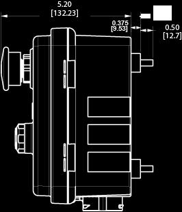
7 Dimensions for Installation Front Inches [mm] Side View
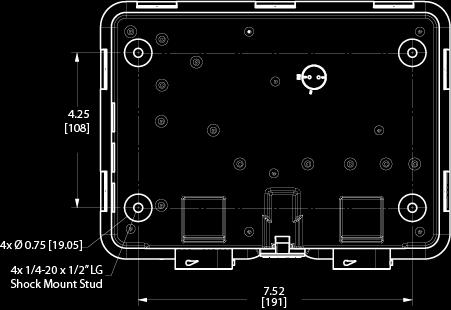
8 Back View
9 PIN Specifications PIN 21 Pin Connector (A) PIN 31 Pin Connector (B) A Unavailable 1 Unavailable B Battery (positive) 2 Unavailable C Unavailable 3 Unavailable D Relay 1, +DC (10A), Default Setting: Crank 4 Unavailable E Battery (negative) 5 Unavailable F J1939 CAN Shield 6 Unavailable G Relay 2, +DC (10A), Default Setting: ECU Enable 7 Unavailable H Unavailable 8 Unavailable J Alternator Excite Output, +DC (1A) 9 Analog Input 3, Default Setting: Not Used K Unavailable 10 Unavailable L Unavailable 11 Unavailable M Unavailable 12 Unavailable N Unavailable 13 Digital Output 1, +DC, (1A), Default Setting: Not in Auto) P Unavailable 14 Digital Input 3, Default Setting: Dual Contact Stop, R S Digital Output 3, -DC, (1A), Default Setting: Throttle Decrease) Digital Output 4, -DC, (1A), Default Setting: Throttle Increase B- 15 Unavailable 16 Unavailable T Frequency Input 17 Relay 3 Common (RLY 3 Defaulted to Not Used) U V J1939 CAN Low (includes terminating resistor, Default to ON) J1939 CAN High, (includes terminating resistor, Default to ON) 10A Max 18 Relay 3 NC (RLY 3 Defaulted to Not Used) 10A Max 19 Relay 3 NO (RLY 3 Defaulted to Not Used) 10A Max W Analog Input 2, Default Setting: Not Used 20 Digital Input 5, Default Setting: Low Lube Oil Level B- X Analog Input 1, Default Setting: Not Used 21 Digital Input 1, Default Setting: Not Used NOTE: Wiring of this device must meet all applicable electrical codes. 22 Unavailable 23 Digital Input 2, Default Setting: Dual Contact Start, B- 24 Digital Output 2, +DC, (1A), Default Setting: Engine Running) 25 Unavailable 26 Battery (negative) 27 Unavailable 28 Unavailable 29 Digital Input 4, Default Setting: Low Coolant Level, B- 30 RS485 (positive) 31 RS485 (negative)
10 Accessories Part Description Number Engine Harness, 21 Position Connector 10 Whip Harness (3m approx.) I/O Harness, 31 Position Connector 10 Whip Harness (3m approx.) Deutsch Connector Kit, 21-pin and 31-pin, Panel Connector Kit Deutsch Connector Kit, 21-pin, Panel Connector Kit, Engine Only Deutsch Connector Kit, 31-pin, Panel Connector Kit, I/O Only Replacement Fuse Door Replacement Fuse Door Pad Replacement Shock Mount Kit Replacement Key Set TEC-10 Programming Kit
11 Specifications Interface Display: Monochrome HR-TFT with backlight 2.7 / 68 mm, WQVGA (400 x 240 pixels) Languages: English, Spanish, German, French, Italian (3) LEDs: Green (mode), Yellow (warning) and Red (shutdown) Operator Controls: (11) Raised silicone keypads, tactile feedback (1) Rotary key switch, power on/off (1) Push switch (red), engine stop Power Supply Operating Voltage: 8-32 VDC, reverse battery polarity and load-dump protected Cranking Power Holdup: 0 VDC up to 50mS (also good for brownout / blackout instances) Current Consumption: Power on in stopped state; 117 ma at 12 VDC. Power on in standby mode; 52 ma at 12 VDC Inputs (9) (5) Digital: configurable (active on High, Low, Open) (3) Analog: configurable (4-20 ma, 0-5V, resistive or digital ground) (1) Frequency: supporting: Magnetic Pickup (30 Hz 10 khz, 2.0 VAC 120 VAC) and Engine Alternator (30 Hz 10 khz, 4.5 VRMS 90 VRMS) Outputs (8) (2) Relay: switched +DC, 10A (1) Relay: Form C (dry / volt-free), 10A (2) Low-side FET: (-DC), 1A (2) High-side FET: (+DC), 1A (1) Dedicated Alternator Excitation: +DC, 1A Communications (1) CAN: J1939 (1) RS485: Modbus RTU Mating Connectors 21 Position, Deutsch HDP SE 31 Position, Deutsch HDP SE Physical / Environmental Enclosure material: Polycarbonate Dimensions (WxHxD): 9.59 x 7.34 x 5.20 in. ( x x mm) Weight: 4 lbs (1.8 kg) IP Rating: IP67 Operating and Storage Temperature: -40 to +85 C (-40 to 185 F) Vibration: 7.86 G rms ( Hz), 3-axes random Shock: ±50G, 3-axes
12
*Approved by CSA for non-hazardous locations (Group Safety Publication IEC Third Edition).
.") PowerCore Model MPC-20 Installation Manual *Approved by CSA for non-hazardous locations (Group Safety Publication IEC 61010-1 Third Edition). Products covered in this document comply with European Council
PowerCore Model MPC-20 Installation Manual *Approved by CSA for non-hazardous locations (Group Safety Publication IEC 61010-1 Third Edition). Products covered in this document comply with European Council
PowerView Model PV485. Installation Manual Section 78
 PowerView Model PV485 Installation Manual 00-02-1018 2017-05-23 Section 78 In order to consistently bring you the highest quality, full-featured products, we reserve the right to change our specifications
HelmView 450 Model HV450. Installation Manual Section 78
 HelmView 450 Model HV450 Installation Manual 00-02-0727 2015-04-16 Section 78 In order to consistently bring you the highest quality, full-featured products, we reserve the right to change our specifications
HelmView Model HV750; HVS750. Installation Manual Section 78
 HelmView Model HV750; HVS750 Installation Manual 00-02-0803 2013-05-20 Section 78 In order to consistently bring you the highest quality, full featured products, we reserve the right to change our specifications
HelmView Model HV750. Installation Manual Section 78
 HelmView Model HV750 Installation Manual 00-02-0803 11-11-11 Section 78 In order to consistently bring you the highest quality, full featured products, we reserve the right to change our specifications
PowerView Model PV750. Installation and Operations Manual Section 78
 PowerView Model PV750 Installation and Operations Manual 00-02-0686 08-20-10 Section 78 In order to consistently bring you the highest quality, full featured products, we reserve the right to change our
MLC 380 R2. For Mechanical Engines. Installation Manual
 MLC 380 R2 For Mechanical Engines Installation Manual In order to consistently bring you the highest quality, full featured products, we reserve the right to change our specifications and designs at any
PowerView Model PV450. Installation and Operation Manual Section 78
 PowerView Model PV450 Installation and Operation Manual 00-02-0732 05-19-2011 Section 78 In order to consistently bring you the highest quality, full featured products, we reserve the right to change our
PowerView Model PV350 and PV380. Installation Manual Section 78
 PowerView Model PV350 and PV380 Installation Manual 00-02-0880 2013-05-17 Section 78 In order to consistently bring you the highest quality, full featured products, we reserve the right to change our specifications
PowerView Model PV1000. Hardware Installation Manual Section 78
 PowerView Model PV1000 Hardware Installation Manual 00-02-0599 07-19-07 Section 78 In order to consistently bring you the highest quality, full featured products, we reserve the right to change our specifications
EMS467 Monitoring System. Installation and Operations Manual Section 40
 EMS467 Monitoring System Installation and Operations Manual 00-02-0672 01-26-10 Section 40 In order to consistently bring you the highest quality, full featured products, we reserve the right to change
PowerView Model PV450. Installation and Operation Manual Section 78
 PowerView Model PV450 Installation and Operation Manual 00-02-0732 2016-02-26 Section 78 In order to consistently bring you the highest quality, full featured products, we reserve the right to change our
PowerView Model PV450. Installation and Operation Manual Section 78
 PowerView Model PV450 Installation and Operation Manual 00-02-0732 10-19-2011 Section 78 In order to consistently bring you the highest quality, full featured products, we reserve the right to change our
TECHNICAL DATASHEET #TDAX050000K CAN
 This cost-effective, compact and robust CAN display shows machine, engine and transmission operating parameters and service codes. Enhanced operating information made available to a vehicle operator improves
PanelView Plus/VersaView CE Terminals and Display Modules
 Installation Instructions PanelView Plus/VersaView CE Terminals and Display Modules (Catalog Numbers 2711P-xxxxxx, 6182H-xxxxxx) English Inside: Overview...2 For More Information...2 Modular Components...3
PowerView TM Model PV350 and PV380. Operations Manual Section 78
 PowerView TM Model PV350 and PV380 Operations Manual 00-02-0879 2012-11-30 Section 78 In order to consistently bring you the highest quality, full featured products, we reserve the right to change our
EX-RC1 Remote I/O Adapter
 EX-RC1 Remote I/O Adapter The EX-RC1 interfaces between Unitronics Vision OPLCs and remote I/O Expansion Modules distributed throughout your system. The adapter is connected to a PLC via CANbus. Each adapter
EXPRESS SETUP. PanelMate 1700 Series PanelMate Power Pro. Cutler-Hammer
 EXPRESS SETUP PanelMate 1700 Series PanelMate Power Pro Cutler-Hammer Installation Unpacking Carefully remove all equipment from the packing cartons and inspect all parts for damage in shipment. Check
INSTALLATION DKM-409 NETWORK ANALYSER WITH HARMONIC MEASUREMENT AND SCOPEMETER. Before installation:
 DKM-409 NETWORK ANALYSER WITH HARMONIC MEASUREMENT AND SCOPEMETER The DKM-409 is a precision instrument designed for displaying various AC parameters in 3-phase distribution panels. Thanks to its isolated
DATA SHEET Compact Genset Controller, CGC 200
 DATA SHEET Compact Genset Controller, CGC 200 Auto start and parameter monitoring Warnings and shutdown protections Includes 5 digital inputs, 5 relay outputs Configurable for other applications Licence-free
INSTALLATION INSTRUCTIONS
 TT-40 9/0 INSTALLATION INSTRUCTIONS Original Issue Date: 9/0 Model: Automatic Transfer Switches Equipped with the Programmable Controller Market: ATS Subject: External Battery Supply Module Kit GM69-KP
General-Purpose Photoelectric Sensor
 General-Purpose Photoelectric Sensor Compact Limit Switch Style with Universal Supply FET output allows for solid state switching of AC or DC Universal AC/DC power supply Choose cable or connector types
OPERATING INSTRUCTIONS 7 SERIES STATIC GENERATORS
 OPERATING INSTRUCTIONS 7 SERIES STATIC GENERATORS GB Contents Page 1 Introduction 4 2 Safety 5 3 Use 6 4 Checking on Delivered Equipment 6 5 General Specification and Dimensions 7 6 Positioning 10 7 Operating
COMPACT FLEXIBLE ALL IN ONE INDUSTRIAL PUMP CONTROL ELECTRONIC MONITORING SYSTEM CONTROLLER
 COMPACT FLEXIBLE ALL IN ONE INDUSTRIAL PUMP CONTROL ELECTRONIC MONITORING SYSTEM CONTROLLER ONE EASY-TO-USE CONTROL. MANY APPLICATIONS. The EMS PRO is a rugged, all-in-one industrial controller designed
EX-RC1 Remote I/O Adapter
 EX-RC1 Remote I/O Adapter The EX-RC1 interfaces between Unitronics Vision OPLCs and remote I/O Expansion Modules distributed throughout your system. The adapter is connected to a PLC via CANbus. Each adapter
Model INSTRUCTION MANUAL DIGITAL MULTIMETER
 Model 57040 INSTRUCTION MANUAL DIGITAL MULTIMETER SAFETY INFORMATION This multimeter has been designed according to IEC 1010 concerning electronic measuring instruments with an overvoltage category (CAT
E2A. Ordering Information. Cylindrical Proximity Sensor. Safe Mounting with Greater Sensing Distance. E2A Cylindrical Proximity Sensor 1
 Cylindrical Proximity Sensor E2A Safe Mounting with Greater Sensing Distance Ensures a sensing distance approximately 1. to 2 times larger than that of any conventional OMRON Sensor. Problems such as the
IO-DI8-TO8 I/O Expansion Module 8 Inputs, 8 Outputs
 IO-DI8-TO8 I/O Expansion Module 8 Inputs, 8 Outputs The IO-DI8-TO8 is an I/O expansion module that can be used in conjunction with specific Unitronics OPLC controllers. The module offers 8 digital inputs,
B&W RearView Camera Installation & Operation
 B&W RearView Camera Installation & Operation CA52 (Camera) FOR MORE INFORMATION WWW.STRATEGICVISTA.COM BEFORE OPERATING THIS SYSTEM, PLEASE READ THIS MANUAL THOROUGHLY AND RETAIN IT FOR FUTURE REFERENCE
Thread length (overall length) material
 material") Cylindrical Proximity Sensor for Mobile Usage Designed and tested to keep your machines moving IP69k tested and certified for highest water resistance e1 type approval (according to automotive directive
Cylindrical Proximity Sensor for Mobile Usage Designed and tested to keep your machines moving IP69k tested and certified for highest water resistance e1 type approval (according to automotive directive
Resolver to Digital Expansion Board
 Resolver to Digital Expansion Board Catalog No. EXB009A01 Installation and Operating Manual 6/98 MN1313 Table of Contents Section 1 General Information............................. 1-1 Introduction....................................
This 4200-RM Rack Mount Kit is for installation in 4200-CAB series cabinets only.
 Keithley Instruments, Inc. 28775 Aurora Road Cleveland, Ohio 44139 (440) 248-0400 Fax: (440) 248-6168 www.keithley.com Model 4200-RM Rack Mount Kit Packing List Introduction NOTE This 4200-RM Rack Mount
Cylindrical Proximity Sensor
 Cylindrical Proximity Sensor A New Series of Easy-to-use and Tough Models with a Yellow Indicator New series of TL-X2C1-GE models with improved performance over the previous TL-X-E models. Also, in addition
5 B&W Rear View System Camera
 5 B&W Rear View System Camera Instruction Manual MODEL: CA453 www.lorexcctv.com Copyright 2007 LOREX Technology Inc. Thank you for purchasing the Lorex 5 Black & White Rear View System Camera. This system
Technical Data Sheet OPUS A3 STANDARD Basic
 Technical Data Sheet OPUS A3 STANDARD Basic 17.01.2018 Errors and technical changes excepted 1 Notes and Warnings Attention! This description is not a substitution for the concerned product s documentation.
Thread length. 27 (40) mm. 27 (44) mm. 27 (40) mm. 34 (50) mm. 34 (49) mm. 39 (60) mm. 39 (54) mm. 44 (65) mm. 44 (59) mm
 mm. 27 (44) mm. 27 (40) mm. 34 (50) mm. 34 (49) mm. 39 (60) mm. 39 (54) mm. 44 (65) mm. 44 (59) mm") Long Distance Cylindrical. Extra long for increased protection and sensing performance triple proximity sensors for flush mounting requirements. designed and tested for extra long life. Ordering Information
Long Distance Cylindrical. Extra long for increased protection and sensing performance triple proximity sensors for flush mounting requirements. designed and tested for extra long life. Ordering Information
MODBUS RTU I/O Expansion Modules - Models C267, C277, and C287. Installation and Operations Manual Section 50
 MODBUS RTU I/O Expansion Modules - Models C267, C277, and C287 Installation and Operations Manual 00-02-0651 09-01-09 Section 50 In order to consistently bring you the highest quality, full featured products,
INSTALLATION INSTRUCTIONS
 www.altroniccontrols.com INSTALLATION INSTRUCTIONS EXACTA 21 MONITORING AND CONTROL SYSTEM CAUTION: The EXACTA 21 CONTROL SYSTEM is CSA CERTIFIED FOR use in Class I, GROUPS C & D, Division 2 hazardous
INSTALLATION MANUAL. LC 200 Electronic Overload Guard. Software versione PW0501 R 0.3
 INSTALLATION MANUAL LC 200 Electronic Overload Guard Software versione PW0501 R 0.3 CONTENTS MAIN FEATURES LC 200 TECHNICAL FEATURES Page 2 SYMBOLS Page 3 WARNINGS Page 3 IDENTIFICATION DATA PLATE Page
Rhino Buffer Module PSM24-BFM600S. Operating Instructions
 Rhino Buffer Module PSM24-BFM600S Operating Instructions RHINO BUFFER MODULE PSM24-BFM600S Description The PSM24-BFM600S Buffer Module will hold the output voltage of a 24 VDC power supply after brownouts
TCNM-ACBB1 Installation Manual
 The TCNM-ACBB1 is a connection box that can be used as an accessory to facilitate system connections for installation and device replacement of several Banner family reading devices. System cabling is
User Manual Entry Line Industrial Fast Ethernet Switch 5x 10/100Base-TX
 User Manual Entry Line Industrial Fast Ethernet Switch 5x 10/100Base-TX Entry Line Fast Ethernet Switch Fast Ethernet Switch for Industrial Use Page 2/11 Table of Contents General... 3 Benefits... 3 Front
DX561 Digital Input/Output Module
 Ordering Data DATA SHEET DX561 Digital Input/Output Module 1 Ordering Data Part No. Description Product Life Cycle Phase *) 1TNE 968 902 R2301 1TNE 968 901 R3101 DX561, digital input/output module, 8 DI
Model 7705 Control Module
 www.keithley.com Model 7705 Control Module User s Guide PA-696 Rev. D / October 2006 A G R E A T E R M E A S U R E O F C O N F I D E N C E Safety Precautions The following safety precautions should be
PowerFlex 400 AC Drive Guide Specification
 PowerFlex 400 AC Drive Guide Specification Adjustable Frequency Drives with Bypass 3.0 50HP @ 208V AC 3.0 350HP @ 480V AC PART 1 GENERAL 1.01 Quality Assurance A. The manufacturer shall have minimum 5
PowerLogic High Density Metering System 1-Meter Enclosure
 PowerLogic High Density Metering System 1-Meter Enclosure Installation Guide 63230-508-211A1 Safety information PowerLogic High Density Metering System 1-Meter Enclosure Important information Read these
DC562, digital input/output module,
 Ordering Data DATA SHEET DC562 Digital Input/Output Module 1 Ordering Data Part No. Description Product Life Cycle Phase *) 1SAP 231 900 R0000 1TNE 968 901 R3101 1TNE 968 901 R3102 1TNE 968 901 R3103 1TNE
Original operating instructions Fail-safe inductive sensor GI711S / / 2010
 Original operating instructions Fail-safe inductive sensor GI7S 704583 / 0 06 / 200 Contents Preliminary note 3. Explanation of symbols 3 2 Safety instructions 4 2. Safety-related requirements regarding
Model A Mini AC/DC Clamp Meter. User's Guide
 Model 380950 80A Mini AC/DC Clamp Meter User's Guide Introduction Congratulations on your purchase of the Extech 80A Mini AC/DC Clamp Meter. The Model 380950 measures AC/DC Current, AC/DC Voltage, Resistance,
Hall-Effect Paddle Joystick
 Hall-Effect Paddle Joystick Robust design for arduous applications Return-to-center or return-to-end options Under-panel depth minimized to 9mm Rated for 5 million cycles Hall-effect sensor technology
Original operating instructions Fail-safe inductive sensor GF711S / / 2013
 Original operating instructions Fail-safe inductive sensor GF7S 8528 / 5 / 23 Contents Preliminary note...3. Explanation of symbols...3 2 Safety instructions...4 2. Safety-related requirements regarding
IP Apartment System Quick Start Guide
 IP Apartment System Quick Start Guide Version 1.0.0 Welcome Thank you for purchasing our device! This quick start guide will help you become familiar with our device in a very short time. Before installation
IGLOO IGLOO EASY INSTRUCTION MANUAL
 ENGLISH EASY C695 C698 INSTRUCTION MANUAL PRELIMINARY Congratulations on choosing a Clay Paky product! We thank you for your custom. Please note that this product, as all the others in the rich Clay Paky
Magnetically Actuated Safety Interlock Switches
 Conforms to EN10, EN292, EN020-1 CSA and BG approved Actual Size Magnetically Actuated Safety Interlock Switches Large selection choose from a large selection of contact configurations housed in plastic,
the Interactive Catalog
 Interactive Catalog Supplements Catalog PDFs If you need detailed product information, or help choosing the right product for your application, see our Interactive Catalog Use the Interactive Catalog to
EX-RC1 Remote I/O Adapter
 EX-RC1 Remote I/O Adapter The EX-RC1 interfaces between Unitronics Vision OPLCs and remote I/O Expansion Modules distributed throughout your system. The adapter is connected to a PLC via CANbus. Each adapter
1.6. Counters, Panel Meters, Tachometers and Timers. Contents Description Fusion Integrated Machine Control Standards and Certifications...
 .6 Contents Standards and Certifications............... Product Selection....................... Technical Data and Specifications........... Dimensions............................ Learn Online Page V3-T-04
Beacon Power Supply Operating and Installation Instruction Manual
 Beacon Power Supply Operating and Installation Instruction Manual Model: BNx000 Page 1 of 27 I. Warnings and Notices I. WARNING - To reduce the risk of fire or electric shock, do not expose this product
PV Rapid Shutdown device
 PV Rapid Shutdown device Installation and Operation Manual Solis-RSD-1G(1:1) Solis-RSD-1G(2:2) Manufacturer: Ginlong (Ningbo) Technologies Co.,Ltd., Ningbo, Zhejiang, P.R.China US Office: 565 Metro Pl.
DC 2-wire Cylindrical Inductive Proximity Sensor
 SERIES DC -wire Cylindrical Inductive Proximity -wire type available Oil resistant Metal embedding possible Amplifier Built-in GX G-6 High performance & ease of use G-8/8U GA-/GH GX GX-N G-8H/8H G-N Robust
CVU-200-KIT. 200 V Bias Tee Kit. Description. Parts list / October 2014 *P A* 1
 Keithley Instruments 28775 Aurora Road Cleveland, Ohio 44139 1-800-935-5595 http://www.keithley.com CVU-200-KIT 200 V Bias Tee Kit Description The CVU-200-KIT Bias Tee Kit consists of three 2600-RBT-200
D6030S - D6030D INSTRUCTION MANUAL. D SIL 3 Switch/Proximity Detector Repeater Relay Output. Models D6030S, D6030D
 D600S - D600D INSTRUCTI MANUAL SIL Switch/Proximity Detector Repeater Relay, DIN Rail, Models D600S, D600D D600 - SIL Switch/Proximity Detector Repeater Relay G.M. International ISM0- Characteristics General
60W Power over Ethernet Waterproof Adapter PoE IEEE BT Single Port Injector for Outdoor Application
 WWW.PHIHONG.COM 60W Power over Ethernet Waterproof Adapter PoE IEEE BT Single Port Injector for Outdoor Application Features Compliant with the IEEE802.3bt Standard Non-Vented Case with Mounting Bracket
User Manual Entry Line Industrial Gigabit Ethernet High Power 60/95 W PoE Injector
 User Manual Entry Line Industrial Gigabit Ethernet High Power 60/95 W PoE Injector Gigabit Ethernet Switch with PoE+ for Industrial Use Page 2/11 Table of Contents General... 3 Benefits... 3 Front View...
Model 2657A-LIM-3 LO Interconnect Module
 Keithley Instruments, Inc. 28775 Aurora Road Cleveland, Ohio 44139 1-888-KEITHLEY http://www.keithley.com Model 2657A-LIM-3 LO Interconnect Module User's Guide Description The Model 2657A-LIM-3 LO Interconnect
Quick Start Guide. SEB-710 I/O Expansion board. Introduction
 SEB-710 I/O Expansion board Revision 1.0 - (March, 2011) Saflec Systems (Pty) Ltd Quick Start Guide Introduction The SEB-710 is an I/O expansion device for additional inputs and outputs. It has eight relay
Installation Sensing distance Connection Output configuration Operation mode NO Operation mode NC
 Standard (thin shape) Inductive Proximity Sensor Thin shape for space saving surface mounting Direct side wall mounting for bracket-less installation Ordering Information DC 3-wire Models Installation
Safegard V4 Panel. Installation Datasheet. Safegard V4 Panel Installation Instructions and Datasheet release 1.7 August 2016
 Safegard V4 Panel Installation Datasheet ELECTROSTATIC SENSITIVE DEVICE This product forms part of a life safety system. Failure to correctly store, handle, install and maintain the product will directly
ASI Systems ML5740A Series
 ML5740A Series Electric Linear Valve Actuators Non-Spring Return APPLICATION The ML5740A series actuators operate standard ASI Systems valves in heating, ventilating and air conditioning (HVAC) applications.
When any of the following symbols appear, read the associated information carefully. Symbol Meaning Description
 Uni-I/O Modules Installation Guide UID-0808R, UID-0808T, UID-1600,UID-0016R, UID-0016T Uni-I/O is a family of Input/Output modules that are compatible with the UniStream control platform. This guide provides
IO-DI8-TO8, IO-DI8-TO8-L I/O Expansion Modules 8 Inputs, 8 Outputs
 IO-DI8-TO8, IO-DI8-TO8-L I/O Expansion Modules 8 Inputs, 8 Outputs The IO-DI8-TO8 and IO-DI8-TO8-L are I/O expansion modules that can be used in conjunction with specific Unitronics OPLC controllers. The
ASI Systems ML5720A Series
 ML5720A Series Electric Linear Valve Actuators Non-Spring Return APPLICATION The ML5720A series actuators operate standard ASI Systems valves in heating, ventilating and air conditioning (HVAC) applications.
IO-AO6X I/O Expansion Module 6 Isolated Analog Outputs
 IO-AO6X I/O Expansion Module 6 Isolated Analog Outputs The IO-AO6X is an I/O Expansion Module that can be used in conjunction with specific Unitronics OPLC controllers. The module offers 6 12-bit isolated
RXTH DUAL ROOM SENSOR / SWITCH
 DUAL ROOM SENSOR / SWITCH FOR TEMPERATURE AND RELATIVE HUMIDITY Mounting and operating instructions Table of contents SAFETY AND PRECAUTIONS 3 PRODUCT DESCRIPTION 4 ARTICLE CODES 4 INTENDED AREA OF USE
CVU-3K-KIT. 3 kv Bias Tee Kit. Description. Parts list / October 2014 *P * 1
 Keithley Instruments 28775 Aurora Road Cleveland, Ohio 44139 1-800-935-5595 http://www.keithley.com CVU-3K-KIT 3 kv Bias Tee Kit Description The CVU-3K-KIT Bias Tee Kit consists of three bias tees for
V E1B Snap-in I/O Module
 V200-18-E1B Snap-in I/O Module The V200-18-E1B plugs directly into the back of compatible Unitronics OPLCs, creating a selfcontained PLC unit with a local I/O configuration. Features 16 isolated digital
QUICK SETUP GUIDE PMC-1000, PMC-1001, PMM-1000, PMB PM Series Power Meter. Safety Information. Equipment Maintenance and Service.
 PM Series Power Meter QUICK SETUP GUIDE PMC-1000, PMC-1001, PMM-1000, PMB-1960 Safety Information DANGER! HAZARD OF ELECTRIC SHOCK, EXPLOSION, OR ARC FLASH Follow safe electrical work practices. See NFPA
P/N: AX Applications: power gen set engine control systems oil and gas equipment automation off-highway machine automation
 TECHNICAL DATASHEET #TDAX031200 11:9 CAN CONTROLLER 11 Inputs (Analog, Digital, Magnetic Pick Up, Universal Signal) 4 Relay, 4 Analog, 1 Valve Driver Outputs 2 CAN (SAE J1939) with Electronic Assistant
Instruction Manual. M Pump Motor Controller. For file reference, please record the following data:
 Instruction Manual M Pump Motor Controller For file reference, please record the following data: Model No: Serial No: Installation Date: Installation Location: When ordering replacement parts for your
GX-5SU(B) is just 5.4 mm 0.213in in diameter, the smallest in existing DC two-wire sensors. It saves you space.
 is just 5.4 mm 0.213in in diameter, the smallest in existing DC two-wire sensors. It saves you space.") DC 2-wire Cylindrical Inductive Proximity SERIES Amplifier Built-in High performance & ease of use Robust in tightening The tightening torque has been improved to approx. four times greater than that of
DC 2-wire Cylindrical Inductive Proximity SERIES Amplifier Built-in High performance & ease of use Robust in tightening The tightening torque has been improved to approx. four times greater than that of
MODEL: R1M-D1. PC Recorders R1M Series. SPECIFICATIONS OF OPTION: Q COATING (For the detail, refer to M-System's web site.)
") PC Recorders R1M Series PC RECORDER (contact output, 32 points) Functions & Features Industrial recorder on PC 32-point open collector outputs Easy system expansion via Modbus RTU Recorded data exportable
PC Recorders R1M Series PC RECORDER (contact output, 32 points) Functions & Features Industrial recorder on PC 32-point open collector outputs Easy system expansion via Modbus RTU Recorded data exportable
IO-PT4. Component identification. User safety and equipment protection guidelines. Unitronics Industrial Automation Systems 1
 IO-PT4 I/O Expansion Module 4 PT100 Inputs (-50 to 460 C) The IO-PT4 is an I/O expansion module that can be used in conjunction with specific Unitronics OPLC controllers. The module offers 4 PT100 inputs
Manual# Installation Manual. 200E Series. DCU 210E/208E Engine Panel RP 210E/220E Remote Panel
 Manual# 1006495 Installation Manual 200E Series DCU 210E/208E Engine Panel RP 210E/220E Remote Panel Installation Manual for the Marine Pro 200E Series ~~~ DCU 210E/208E Diesel Engine Control Unit RP 210E/220E
DC561, digital input/output module,
 Ordering Data DATA SHEET DC561 Digital Input/Output Module 1 Ordering Data Part No. Description Product Life Cycle Phase *) 1TNE 968 902 R2001 DC561, digital input/output module, 16 configurable inputs/outputs,
EP/2 Installation Instructions
 1 2 3 4 7 ENTER 0 5 6 8 9 CLEAR + - LOGIC ONE EP/2 EP/2 Installation Instructions DOC. #569011000 A 7/30/04 PRINTED IN U.S.A. Regulatory Compliance Safety This device has been tested and found to be in
A Axis M-Functions Level 1 A Axis Standard A Axis SMT Level 2. Each console includes the following:
 Hardware List The 3000M Crusader II Upgrade system has been custom configured to provide the necessary hardware required for installation on your machine. Verify that you have received all the correct
S7999D SOLA Operator Interface Display
 S7999D Operator Interface Display INSTALLATION INSTRUCTIONS APPLICATION The S7999D is microprocessor-based color touch-screen Operator Interface (OI) display that provides an operator interface for monitoring
Installation Guide V290 (Color) This guide provides basic information for Unitronics LCD color touchscreen models V C30B and V T40B.
 This guide provides basic information for Unitronics LCD color touchscreen models V C30B and V T40B.") Vision OPLC Installation Guide V290 (Color) This guide provides basic information for Unitronics LCD color touchscreen models V290-19-C30B and V290-19-T40B. General Description Vision OPLCs are programmable
Vision OPLC Installation Guide V290 (Color) This guide provides basic information for Unitronics LCD color touchscreen models V290-19-C30B and V290-19-T40B. General Description Vision OPLCs are programmable
TEC100 USER/INSTALLER MANUAL V2.0 REV. 03/2018
 TEC100 USER/INSTALLER MANUAL V2.0 REV. 03/2018 00. CONTT 01. SAFETY INSTRUCTIONS INDEX 01. SAFETY INSTRUCTIONS STANDARDS TO FOLLOW 02. PRODUCT PRODUCT PROFILE TECHNICAL PARAMETERS 03. INSTALLATION PRODUCT
When any of the following symbols appear, read the associated information carefully. Symbol Meaning Description
 Uni-I/O Wide Modules Installation Guide UID-W1616R, UID-W1616T Uni-I/O Wide is a family of Input/Output modules that are compatible with the UniStream control platform. Wide Modules are 1.5 times as wide
SORDS ELECTRIC ~ MA7200. Sensorless Vector AC Inverter.
 www.sordselectric.com MA7200 Sensorless Vector AC Inverter Features and Benefits Sensorless Vector The MA7200 has precise speed and torque control for the most demanding system performance and simple set-up
E101 - Strain Gauge Transducer Display Module. Contents
 E101 - Strain Gauge Transducer Display Module Contents Torque Transducer Display Interface: TSE3249R Strain Gauge Transducer Display Interface [E101] Operating Guide: TSE2097V (Includes Introduction, Description
SMI-100 Stack Monitoring Interface Installation & Operation Manual
 SMI-100 Stack Monitoring Interface Installation & Operation Manual Aquion Energy, Inc. 32 39th Street Pittsburgh, PA 15201 +1 412.904.6400 aquionenergy.com AQ-OP-00015_C 12.23.16 2016 Aquion Energy, Inc.
User Manual. cmt-iv5 Startup Guide
 User Manual cmt-iv5 Startup Guide v 2.2 JAN 8, 2016 Table of Contents Chapter1. Overview... 1 1.1. Specification... 1 1.2. Dimensions... 2 1.3. Ethernet port... 3 1.4. CR1225 battery... 3 1.5. Power connection...
This guide provides basic information for Unitronics Models 230/260/280/290 (Non-color Screens).
.") Vision OPLC Installation Guide Models 230/260/280/290 (Non-color Screens) This guide provides basic information for Unitronics Models 230/260/280/290 (Non-color Screens). General Description Vision OPLCs
Vision OPLC Installation Guide Models 230/260/280/290 (Non-color Screens) This guide provides basic information for Unitronics Models 230/260/280/290 (Non-color Screens). General Description Vision OPLCs
Rotary Measurement Technology Absolute Encoders, Singleturn
 -40 to 80 C IP Safety-LockTM High rotational speed Temperature High IP High shaft load capacity Shock/ vibration resistant Magnetic field proof Short-circuit proof Reverse polarity protection Reliable
DI561 Digital Input Module
 Ordering Data DATA SHEET DI561 Digital Input Module 1 Ordering Data Part No. Description Product Life Cycle Phase *) 1TNE 968 902 R2101 1TNE 968 901 R3101 1TNE 968 901 R3103 1TNE 968 901 R3105 DI561, digital
When any of the following symbols appear, read the associated information carefully. Symbol Meaning Description
 Uni-I/O Modules Installation Guide UIA-0402N Uni-I/O is a family of Input/Output modules that are compatible with the UniStream control platform. This guide provides basic installation information for
REDUNDANCY MODULE TSP-REM360 AND TSP-REM600
 REDUNDANCY MODULE TSP-REM360 AND TSP-REM600 Operating Instructions Seite 1 Dimensions drawings: TSP-REM360 Weight: 0.882lb Gewicht: 0.40kg Seite 2 Dimensions drawings: TSP-REM600 Bottom view Top view Side
1 Description. 2 Specifications. Product Installation Document. Honeywell 12 Clintonville Road Northford, CT
 Honeywell 12 Clintonville Road Northford, CT 06472 http://www.honeywellpower.com HP600ULACM4CB HP600ULACM8CB Access Control Power Supply/Charger with Power Distribution Controller PN 52395:A 1/05/06 ECN