Designing High-Speed Memory Subsystem DDR. using. Cuong Nguyen. Field Application Engineer
|
|
|
- Dorothy Gibbs
- 5 years ago
- Views:
Transcription


1 Designing High-Speed Memory Subsystem using DDR Cuong Nguyen Field Application Engineer

2 Your Design for Excellence Partner Since 1997 EDA Direct has helped customers in the High Tech industry with design tools, training, and services
3 Best in Class Design Tools we support PADS PCB Layout DxDesigner Schematic Capture Expedition PCB Enterprise System Hyperlynx Signal/Power Integrity Modelsim/Questa FPGA/ASIC/System Simulation FloTHERM CFD Thermal Analysis Valor PCB Manufacturing/Assy/Test
4 Agenda DDRx Overview Design Considerations Integrated Design Flow DDR4 New Drive Standards Variable Vref calculation Eye Generation/Measurements New features Power Integrity Effects
5 DDR Feature Comparison DDR DDR2 DDR3 Data Rate Mbps Mbps Mbps System support 4 slots 8 loads 2 slots 4 loads 2 slots 4 loads 1600 Mbps = 1 slot Signaling Technology DQS signals SSTL_2 SSTL_18 SSTL_15 Bi-directional single ended Bi-directional single or differential Bi-directional differential ODT No Yes Yes Signal leveling No No Yes
6 Overview DDR3 vs. DDR4 DDR3 DDR4 Comments VDD/VDDQ/VPP 1.5/1.5/NA 1.2/1.2/2.5 Up to 20% power saving (1.35/1.35/NA) Clock Frequencies MHz MHz+ Higher BW CAS Latency 5~14 9~24 Vref VDDQ/2 (Ext) Internal DQ Validation Setup/Hold Data Eye Borrowed from SERDES Data Termination VDDQ/2 (VTT) VDDQ Asymmetric Term. Add/Cmd/Termination VDDQ/2 (VTT) VDDQ/2 I/O Standard SSTL15 POD12 Power savings on 1 bits On Chip Error Detection No Parity (Cmd/Add) Server Class CRC (DQ) Bank Grouping No 4 Ping-Pong for efficient use
7 Overview LPDDR3 vs LPDDR4 LPDDR3 LPDDR4 Comments CLK MHz MHz 2x speed (possibly more) Bandwidth 12.8GB/s (2ch) 25.6GB/s (2ch) Higher BW VDD2/VDDQ/VDD1 1.2/1.2/ /1.1/1.8 Power reduced 10% I/O Interface HSUL LVSTL 40% I/O Power reduction DQ ODT Vtt Term VSSQ Term vs. POD CA ODT No term VSS Term (optional) Vref External Internal

8 Overview Speed related Eye challenges Semicon West: High Performance & Low Power Memory Trends SK Hynix

9 Design Considerations Layout/Route Avoid crossing splits in reference planes (discontinuities) Minimize Inter Symbol Interference (ISI) using matched Impedances Minimize Crosstalk by isolating sensitive bits (ie. Strobes) Match traces within byte lanes (DQ, DM, DQS) to minimize skews Power Supplies Use precision resistors for V REF Short/Wide traces to minimize L and loss 15~25mil clearance from V REF to adjacent traces to minimize coupling Decouple high frequency Power Supply noise w/caps Signaling DQ Driver Impedance Matching with proper drive strengths ODT is a must for better Signal Integrity (if not used then use T-brances or dumping resistor to minimize reflections Choose termination carefully to balance power consumption, signal swing, and reflection Use 2T timing for Address/Command

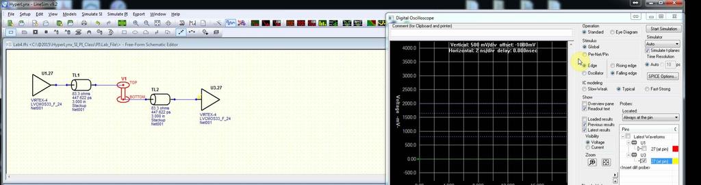
10 PreLayout SI Simulation From-Concept-to-Chip-to-Board
 Diff pair")
11 Sketch Routing with PADS (video) Constraint-driven routing Designer knows where the traces should be routed Precise location of traces & vias Control style of routing incl serpentines Things to observe while routing DDRx Width & clearance rules Placement intentions Netline organization Layer restrictions Pad/via entry rules (angle, size) Diff pair rules
 2014")
12 Using Sketch routing with DDR3 (video)
13 DDR4 Features
14 New Drive Standards DDR 4 - Pseudo Open Drain Address/Command/Control (SSTL) LPDDR4 - Low Voltage Swing Terminated Logic Both Data and Address New standard only effects IBIS files Effects of new standards visible in simulation results
15 New Drive Standards Difference Termination DDR4 Terminated to VDDQ DDR3 Terminated to VDDQ/2 or VTT
16 New Drive Standards LPDDR4 LVSTL for LPDDR4 terminates to GND
17 New POD Drive Standards Why? Current still flows when driving Low I DDR4 (ie. More) I DDR
18 New Drive Standards Why? No current draw when driving a High No Current DDR4 I DDR
19 Power Savings with DBI (Data Bit Inversion) Ensure more 1 s than 0 s with POD If more than 4-bits in a byte are 0, toggle bits and set DBI = 0 DBI shared with DM => only one feature enabled DBI pin is I/O (Reads and Writes) Signal transitioning from one byte to next is less than 4-bits! Minimize SSN!
20 Implications for SI What does Asymmetric Termination mean for reference threshold voltage ( center voltage of eye ) Take average voltage of high and low at receiver Assume a very short trace for sake of simple calculations Assume balanced High and Low drive strength Rt = Term Resistance Zo = Transmission Line Impedance Zd = Driver output Impedance
21 DDR3 Eye Center Voltage When Driving High When Driving Low = = = 2 + = = 2 = =
22 DDR4 Center Voltage When Driving High When Driving Low = = + = = + 2 = Threshold value is NOT constant and depends on the setup!
23 DDR3 vs. DDR4 Vcent Comparison DDR3, Vcent = Vdd/2. Constant, regardless of setup DDR4, Vcent = f(rt, Zd) Varies from setup to setup Varies from read to write Varies across access to different DRAMs Always greater than Vdd/

24 Simple Comparison Controller -> 50 Ohm T-Line -> DRAM Vary DRAM s ODT to see center level of eye 2400Mbps Data rate


25 DDR3 sweeping Rx ODT No change in Center of Eye with ODT


26 DDR4 Eye shifting Eye center shifts with ODT change


27 LPDDR4 Eye shifting Eye center shifts with ODT change


28 Input Threshold Levels DDR3 Absolute Vinh/vinl thresholds stayed constant in DDR3 across designs DDR4 Absolute Vih/Vil threshold levels can change in DDR
29 Vref for a Device Need Precision programmable reference voltage Center voltage can vary across pins Individual Vref per pin may be too expensive Silicon and power How to determine voltage used for all pins?
30 Determining Vref Avg 8 bit device, one Vref resource (Assume) Eye-center of bit different for each bit 800mV 750mV 730mV 725mV 720mV 710mV 705mV 700mV Option 1: Average of all signals = Option 2: Average of extreme signals =
31 Average Margin Loss Comparison Option 1: Average of all signals Option 2: Average of extreme signals = 798mV (Vinh) = 662mV (Vinl) = 818mV (Vinh) = 682mV (Vinl)
32 Average Margin Loss Comparison 800mV 750mV 730mV 725mV 720mV 710mV 705mV 700mV Assume eye height same at all pins, Eye height of 260mV (Vcenter +/- 130mV) (Not strictly true, but 800mV is still worst case) 800mV center signal swings between 670mV to 930mV 930mV Option = 798mV (Vinh) = 662mV (Vinl) Problems with Low mV mV Option = 818mV (Vinh) = 682mV (Vinl) Better Margins High/Low

33 Vref for DDR4 DRAM (JEDEC) Single Voltage, regardless of x4, x8 or x16 Ref Voltage is average of Min and Max center-voltages JC-42.3C, Ballot A

34 Vref for DDR4 DRAM Programmable Range from 45% of Vdd to 92.5% of Vdd Step size can be between 0.5%Vddq to 0.8%Vddq Exact value will be specific to the DRAM and should be in the datasheet

35 Vref for LPDDR4 DRAM Separate Data and CA reference voltages
36 Vref for Controller (Read) Single Vref for entire channel Inexpensive, easy for controller to implement Greater similarity required in DQ signal characteristics
37 Vref for Controller (Read) Single Vref for each DRAM in the rank Allows for grouping of signals going to each DRAM
38 Vref for Controller (Read) Single Vref for each Lane in the rank Allows for grouping of signals going to each Lane Differs from previous setup only for x16 DRAMs
39 Vref for Controller (Read) Single vs Multi-Rank support Cost vs Layout feasibility

40 In the DDR Wizard Controller Vref Controller can have Vref per lane, DRAM or single Vref for all DQ signals Can have single Vref for all ranks, or separate Vref per rank Overide defaults
41 Eye Generation Concept of Eye borrowed from SerDes No self-clocking, or clock recovery scheme Uses explicit Clock/Strobe (Source Synchronous) In simulation run, cannot just specify frequency Must incorporate clock/strobe
42 DDR4 Data Mask (JEDEC) Eye Mask = Vertically centered at Threshold and Horizontally centered around Strobe zero crossings Data compliance determined by Eye-Mask Address still using setup/hold as with DDR3 (SSTL) Random region definition still being decided (VIHL_AC) o Value is zero for now o May change for higher speeds


43 LPDDR4 Mask Both Data and CA determined by Eye-Mask
44 DDR4 AC Threshold VIHL_AC measured on both high and low sides

45 In the DDR Wizard Results Aggregate results and per-bit results Aggregate contains eye-level results and worst-case results Per-bit results contain measurements for every clock cycle ResAMI_data_aggregated.sds file shows eye-diagrams and aggregate measurements Eye mask centered around Vref and DQS zero-crossing
46 New DDR4 Features
47 New Features - Calibration DDR4 now enables per-bit training/calibration Enables DQ delay calibrations to DQS Help align mismatch signals within a lane DDR4 Continues to support Write leveling LPDDR4 continues to support CA and DQ training
48 New Feature RTT_PARK Used when ODT is de-asserted, or disabled DDR3, this would be a Hi-Z DDR4, this triggers RTT_PARK (Optional) Eg. Writing to rank 1 May need weak termination in rank 3, Hi-Z in Rank2 Useful in multi-rank systems

49 In the DDR Wizard RTT_PARK RTT_NOM, RTT_WR, RTT_PARK not directly mapped ODT Disabled, ODT1 Enabled, ODT2 Enabled Balance between corner case of using all ODTs vs. ease of use
50 New Features DDR4 Par/CRC Reliability Features PAR bit for Address Detect even parity error in Address lines Execute command only if no error CRC for DQ writes (optional) 8-bit CRC for 72-bits of data Controller generates data + CRC block Combined data passed in specified order DRAM executes CRC check, and signals error using ALERT_n pin Useful for Server Market!
51 New Feature Bank Group Feature reinstated since Core DRAM frequency stays relatively fixed and the need to reduce pre-fetch size of DDR4 Pre-fetch delay for consecutive accesses within a Bank Group is greater than between groups Need to store data across groups so that data is ping-ponged across groups to optimize timing More firmware/software task than SI

52 New Feature Gear down Mode For speeds at 2666MT/s and above, reduce DRAM internal clock speed Address/Command runs at ¼ rate of data Help in Addr/Cmd signaling in multi-rank cases
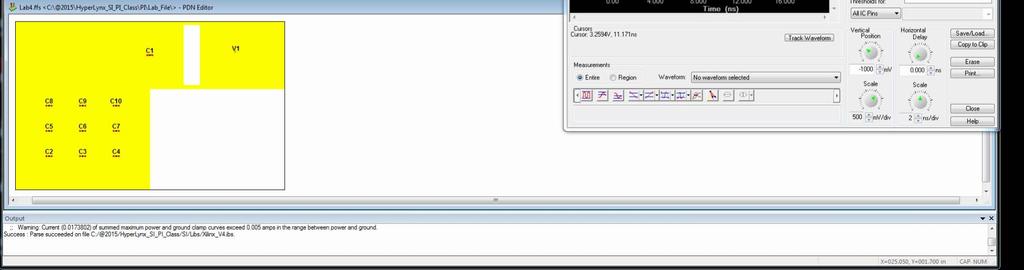
53 Power Integrity Effects


54 Signal Integrity/Power Integrity Co-Simulation Use SI/PI Co-Simulation to see effects of VIA structures and bypassing/decoupling on sensitive signals (ie. DQS/CLK) Coupling between VIAs, stub length effects, etc.. Through-hole, buried, stacked, etc.. Do what-if analysis on PDN to fix problems
55 SI/PI Co-Simulation (video)

56 Power Integrity/Thermal Integrity Co-simulation Analyze Joule Heating effects in traces Identify/localize sensitive area on board Minimize field failures and increase product reliability


57 Power Integrity Effects - Ripples Lane being driven between two components 7-bits driving PRBS, 1-bit at

58 Power Integrity Effects - Ripples 150mV noise from switching of other bits in lane


59 Integrated Design Flow - Summary Tight tool integration (no export/import) Single debug environment Minimize errors, increase accuracy Single Support Source SI/PI/Thermal Simulation Pre/Post Architectural/Technology Investigation Performance/Feasibility Analysis Noise/Crosstalk/Termination/EMI Constraints Constraints Stackup/Placements Length/Impedance/via Board DDR Schematic Library/Symbols Design Variants Layout/Route Design Constraints Minimize errors and increase product reliability!
60 Contact Info EDA Direct Inc. (408) (888) 669-9EDA To enroll for our upcoming seminars, workshops, training classes, and view demo videos of our products visit
High-Speed DDR4 Memory Designs and Power Integrity Analysis
 High-Speed DDR4 Memory Designs and Power Integrity Analysis Cuong Nguyen Field Application Engineer cuong@edadirect.com www.edadirect.com 2014 1 PCB Complexity is Accelerating Use of Advanced Technologies
DDR4 Design And Verification In Hyperlynx LINESIM/Boardsim
 DDR4 Design And Verification In Hyperlynx LINESIM/Boardsim Rod Strange Business Development Manager Teraspeed Consulting A Division of Samtec April 2016 Outline Objective/Goal DDR4 vs. DDR3 from the SI/PI
Board Design Guidelines for PCI Express Architecture
 Board Design Guidelines for PCI Express Architecture Cliff Lee Staff Engineer Intel Corporation Member, PCI Express Electrical and Card WGs The facts, techniques and applications presented by the following
LPDDR4: Evolution for new Mobile World
 LPDDR4: Evolution for new Mobile World 2013.08.06 JungYong(JY) Choi Senior Manager Samsung Semiconductor Inc. 1 / 22 Legal Disclaimer This presentation is intended to provide information concerning memory
ADQVD1B16. DDR2-800+(CL4) 240-Pin EPP U-DIMM 2GB (256M x 64-bits)
 240-Pin EPP U-DIMM 2GB (256M x 64-bits)") General Description ADQVD1B16 DDR2-800+(CL4) 240-Pin EPP U-DIMM 2GB (256M x 64-bits) The ADATA s ADQVD1B16 is a 256Mx64 bits 2GB(2048MB) DDR2-800(CL4) SDRAM EPP memory module, The SPD is programmed to
General Description ADQVD1B16 DDR2-800+(CL4) 240-Pin EPP U-DIMM 2GB (256M x 64-bits) The ADATA s ADQVD1B16 is a 256Mx64 bits 2GB(2048MB) DDR2-800(CL4) SDRAM EPP memory module, The SPD is programmed to
HyperLynx DDRx Interface Analysis. Student Workbook
 HyperLynx DDRx Interface Analysis Student Workbook 2017 Mentor Graphics Corporation All rights reserved. This document contains information that is trade secret and proprietary to Mentor Graphics Corporation
DDR System Simulation: What Issue to Simulate
 DDR System Simulation: What Issue to Simulate Asian IBIS Summit Tokyo, Japan November 17, 2017 Shinichi Maeda 1 JEDEC DDR Specifications DDR DDR2 DDR3 DDR3L DDR3U DDR4 Vdd 2.5 1.8 1.5 1.35 1.25 1.2(IO)
Breakthrough Insight into DDR4/LPDDR4 Memory Greater Than 2400 Mb/s
 Breakthrough Insight into DDR4/LPDDR4 Memory Greater Than 2400 Mb/s January 2015 Jennie Grosslight Product Manager Agenda Overview Benefits and challenges for DDR4 and LPDDR4 >2400Mb/s Breakthrough Insight
RML1531MH48D8F-667A. Ver1.0/Oct,05 1/8
 DESCRIPTION The Ramaxel RML1531MH48D8F memory module family are low profile Unbuffered DIMM modules with 30.48mm height based DDR2 technology. DIMMs are available as ECC (x72) modules. The module family
DDR4: Designing for Power and Performance
 DDR4: Designing for Power and Performance Agenda Comparison between DDR3 and DDR4 Designing for power DDR4 power savings Designing for performance Creating a data valid window Good layout practices for
SC64G1A08. DDR3-1600F(CL7) 240-Pin XMP(ver 2.0) U-DIMM 1GB (128M x 64-bits)
 240-Pin XMP(ver 2.0) U-DIMM 1GB (128M x 64-bits)") SC64G1A08 DDR3-1600F(CL7) 240-Pin XMP(ver 2.0) U-DIMM 1GB (128M x 64-bits) General Description The ADATA s SC64G1A08 is a 128Mx64 bits 1GB(1024MB) DDR3-1600(CL7) SDRAM XMP (ver 2.0) memory module, The
SC64G1A08 DDR3-1600F(CL7) 240-Pin XMP(ver 2.0) U-DIMM 1GB (128M x 64-bits) General Description The ADATA s SC64G1A08 is a 128Mx64 bits 1GB(1024MB) DDR3-1600(CL7) SDRAM XMP (ver 2.0) memory module, The
Electrical optimization and simulation of your PCB design
 Electrical optimization and simulation of your PCB design Steve Gascoigne Senior Consultant at Mentor Graphics Zagreb, 10. lipnja 2015. Copyright CADCAM Group 2015 The Challenge of Validating a Design..
D G28RA 128M x 64 HIGH PERFORMANCE PC UNBUFFERED DDR3 SDRAM SODIMM
 D93 6865G28RA 128M x 64 HIGH PERFORMANCE PC3-10600 UNBUFFERED DDR3 SDRAM SODIMM Features 240- Dual In-Line Memory Module (UDIMM) Inputs and outputs are SSTL-15 compatible V DD = V DDQ = 1.5V ± 0.075V Differential
LE4ASS21PEH 16GB Unbuffered 2048Mx64 DDR4 SO-DIMM 1.2V Up to PC CL
 LE4ASS21PEH 16GB Unbuffered 2048Mx64 DDR4 SO-DIMM 1.2V Up to PC4-2133 CL 15-15-15 General Description This Legacy device is a JEDEC standard unbuffered SO-DIMM module, based on CMOS DDR4 SDRAM technology,
QDR II SRAM Board Design Guidelines
 8 emi_dg_007 Subscribe The following topics provide guidelines for you to improve your system's signal integrity and layout guidelines to help successfully implement a QDR II or QDR II+ SRAM interface
Symbol Parameter Min Typ Max VDD_CORE Core power 0.9V 1.0V 1. 1V. VDD33 JTAG/FLASH power 2.97V 3.3V 3.63V
 1 Introduction The user guide provides guidelines on how to help you successfully design the CME-M7 board which includes the power supply, configuration, clock, DDR2 or DDR3, high speed USB, LVDS and ADC
Interfacing the RC32438 with DDR SDRAM Memory
 Interfacing the RC32438 with DDR SDRAM Memory Application Note AN-371 Revision History By Kasi Chopperla and Harold Gomard July 3, 2003: Initial publication. October 23, 2003: Added DDR Loading section.
APDS Wizard v4 for Nexxim/Designer 4.0 Specially optimized for DDR2/3 SI. Ansoft Korea Team
 APDS Wizard v4 for Nexxim/Designer 4.0 Specially optimized for DDR2/3 SI Ansoft Korea Team APDS Wizard v4 All-Renewed, Enhanced Wizard. Version 4 means this new wizard would work with Designer/Nexxim v4
Organization Row Address Column Address Bank Address Auto Precharge 128Mx8 (1GB) based module A0-A13 A0-A9 BA0-BA2 A10
 based module A0-A13 A0-A9 BA0-BA2 A10") GENERAL DESCRIPTION The Gigaram is ECC Registered Dual-Die DIMM with 1.25inch (30.00mm) height based on DDR2 technology. DIMMs are available as ECC modules in 256Mx72 (2GByte) organization and density,
GENERAL DESCRIPTION The Gigaram is ECC Registered Dual-Die DIMM with 1.25inch (30.00mm) height based on DDR2 technology. DIMMs are available as ECC modules in 256Mx72 (2GByte) organization and density,
HYPERLYNX DDR3 Wizard
 HYPERLYNX DDR3 Wizard w w w. m e n t o r. c o m HyperLynx DDR3 Wizard Virtual Lab Exercise Guide This tutorial outlines the steps for completing a DDR3 Wizard DDR analysis example in HyperLynx BoardSim.
Technical Note DDR2 (Point-to-Point) Package Sizes and Layout Basics
 Package Sizes and Layout Basics") Introduction Technical Note DDR2 (Point-to-Point) Package Sizes and Layout Basics Introduction Point-to-point designers face many challenges when laying out a new printed circuit board (PCB). The designer
Introduction Technical Note DDR2 (Point-to-Point) Package Sizes and Layout Basics Introduction Point-to-point designers face many challenges when laying out a new printed circuit board (PCB). The designer
Real Time Embedded Systems
 Real Time Embedded Systems " Memories " rene.beuchat@epfl.ch LAP/ISIM/IC/EPFL Chargé de cours LSN/hepia Prof. HES 1998-2008 2 General classification of electronic memories Non-volatile Memories ROM PROM
Technical Note LPSDRAM Unterminated Point-to-Point System Design: Layout and Routing Tips
 Introduction Technical Note LPSDRAM Unterminated Point-to-Point System Design: Layout and Routing Tips Introduction Background Low-power (LP) SDRAM, including both low-power double data rate (LPDDR) and
Memory Module Specifications KVR667D2Q8F5K2/8G. 8GB (4GB 512M x 72-Bit x 2 pcs.) PC CL5 ECC 240-Pin FBDIMM Kit DESCRIPTION SPECIFICATIONS
 PC CL5 ECC 240-Pin FBDIMM Kit DESCRIPTION SPECIFICATIONS") Memory Module Specifications KVR667DQ8F5K/8G 8GB (4GB 5M x 7-Bit x pcs.) PC-5300 CL5 ECC 40- FBDIMM Kit DESCRIPTION s KVR667DQ8F5K/8G is a kit of two 4GB (5M x 7-bit) PC-5300 CL5 SDRAM (Synchronous DRAM)
Memory Module Specifications KVR667DQ8F5K/8G 8GB (4GB 5M x 7-Bit x pcs.) PC-5300 CL5 ECC 40- FBDIMM Kit DESCRIPTION s KVR667DQ8F5K/8G is a kit of two 4GB (5M x 7-bit) PC-5300 CL5 SDRAM (Synchronous DRAM)
2GB DDR3 SDRAM SODIMM with SPD
 2GB DDR3 SDRAM SODIMM with SPD Ordering Information Part Number Bandwidth Speed Grade Max Frequency CAS Latency Density Organization Component Composition Number of Rank 78.A2GC6.AF1 10.6GB/sec 1333Mbps
8. Selectable I/O Standards in Arria GX Devices
 8. Selectable I/O Standards in Arria GX Devices AGX52008-1.2 Introduction This chapter provides guidelines for using industry I/O standards in Arria GX devices, including: I/O features I/O standards External
APPROVAL SHEET. Apacer Technology Inc. Apacer Technology Inc. CUSTOMER: 研華股份有限公司 APPROVED NO. : T0031 PCB PART NO. :
 Apacer Technology Inc. CUSTOMER: 研華股份有限公司 APPROVAL SHEET APPROVED NO. : 90003-T0031 ISSUE DATE MODULE PART NO. : July-28-2011 : 78.02GC6.AF0 PCB PART NO. : 48.18220.090 IC Brand DESCRIPTION : Hynix : DDR3
Modern Memory Interfaces (DDR3) Design with ANSYS Virtual Prototype approach
 Design with ANSYS Virtual Prototype approach") Modern Memory Interfaces (DDR3) Design with ANSYS Virtual Prototype approach 1 ANSYS, Inc. Proprietary 2012 ANSYS, Inc. November 14, 2012 1-1 Agenda DDR Design Challenges How does simulation solve these
Modern Memory Interfaces (DDR3) Design with ANSYS Virtual Prototype approach 1 ANSYS, Inc. Proprietary 2012 ANSYS, Inc. November 14, 2012 1-1 Agenda DDR Design Challenges How does simulation solve these
Datasheet. Zetta 4Gbit DDR4 SDRAM. Features. RTT_NOM switchable by ODT pin Asynchronous RESET pin supported
 Zetta Datasheet Features VDD=VDDQ=1.2V +/- 0.06V Fully differential clock inputs (CK, CK ) operation Differential Data Strobe (DQS, DQS ) On chip DLL align DQ, DQS and DQS transition with CK transition
Organization Row Address Column Address Bank Address Auto Precharge 256Mx4 (1GB) based module A0-A13 A0-A9 BA0-BA2 A10
 based module A0-A13 A0-A9 BA0-BA2 A10") GENERAL DESCRIPTION The Gigaram GR2DR4BD-E4GBXXXVLP is a 512M bit x 72 DDDR2 SDRAM high density ECC REGISTERED DIMM. The GR2DR4BD-E4GBXXXVLP consists of eighteen CMOS 512M x 4 STACKED DDR2 SDRAMs for 4GB
GENERAL DESCRIPTION The Gigaram GR2DR4BD-E4GBXXXVLP is a 512M bit x 72 DDDR2 SDRAM high density ECC REGISTERED DIMM. The GR2DR4BD-E4GBXXXVLP consists of eighteen CMOS 512M x 4 STACKED DDR2 SDRAMs for 4GB
Making Your Most Accurate DDR4 Compliance Measurements. Ai-Lee Kuan OPD Memory Product Manager
 Making Your Most Accurate DDR4 Compliance Measurements Ai-Lee Kuan OPD Memory Product Manager 1 Agenda DDR4 Testing Strategy Probing Analysis Tool Compliance Test Conclusion 2 DDR4 Testing Strategy 1.
90000 DSO/DSA Series Oscilloscopes
 DDR4 Keysight Compliance Infiniium Test Bench 90000 DSO/DSA Series Oscilloscopes ADS DDR4 DesignGuide and Compliance Test Bench 1 Contents Installing the DDR4 Compliance Test Bench... 2 Prerequisites...
Memory Solutions. Industry Trends and Solution Overview
 Memory Solutions Industry Trends and Solution Overview Outline Industry Trends & Market Status Existing SDRAM Technologies DDR3, DDR3L, DDR3U DDR3 Signaling LPDDR2/LPDDR3 LPDDR3 Signaling DDR4 DDR4 Signaling
4GB Unbuffered VLP DDR3 SDRAM DIMM with SPD
 4GB Unbuffered VLP DDR3 SDRAM DIMM with SPD Ordering Information Part Number Bandwidth Speed Grade Max Frequency CAS Latency Density Organization Component Composition 78.B1GE3.AFF0C 12.8GB/sec 1600Mbps
KVR667D2D8F5/1G 1GB 128M x 72-Bit PC CL5 ECC 240-Pin FBDIMM
 Memory Module Specifications KVR667D2D8F5/1G 1GB 128M x 72-Bit PC2-5300 CL5 ECC 240- FBDIMM Description: This document describes ValueRAM's 1GB (128M x 72-bit) PC2-5300 CL5 (Synchronous DRAM) "fully buffered"
High Performance DDR4 interfaces with FPGA Flexibility. Adrian Cosoroaba and Terry Magee Xilinx, Inc.
 High Performance DDR4 interfaces with FPGA Flexibility Adrian Cosoroaba and Terry Magee Xilinx, Inc AGENDA System Requirements for FPGA based systems Higher Bandwidth, Increased Flexibility, Lower Power
PC2-5300/PC DDR2 SDRAM Unbuffered DIMM Design Specification Revision 3.1 October 2008
 Page 4.20.13-1 4.20.13-240-Pin PC2-5300/PC2-6400 DDR2 SDRAM Unbuffered DIMM Design Specification PC2-5300/PC2-6400 DDR2 SDRAM Unbuffered DIMM Design Specification Revision 3.1 October 2008 JEDED Standard
SDRAM DDR3 256MX8 ½ Density Device Technical Note
 SDRAM DDR3 256MX8 ½ Density Device Technical Note Introduction This technical note provides an overview of how the SGG128M8V79DG8GQF-15E DDR3 SDRAM device is configured and tested as a 1Gb device. This
2GB DDR3 SDRAM 72bit SO-DIMM
 2GB 72bit SO-DIMM Speed Max CAS Component Number of Part Number Bandwidth Density Organization Grade Frequency Latency Composition Rank 78.A2GCF.AF10C 10.6GB/sec 1333Mbps 666MHz CL9 2GB 256Mx72 256Mx8
Implementing Bus LVDS Interface in Cyclone III, Stratix III, and Stratix IV Devices
 Implementing Bus LVDS Interface in Cyclone III, Stratix III, and Stratix IV Devices November 2008, ver. 1.1 Introduction LVDS is becoming the most popular differential I/O standard for high-speed transmission
PC2-6400/PC2-5300/PC2-4200/PC Registered DIMM Design Specification Revision 3.40 August 2006
 JEDEC Standard No. 21C Page 4.20.10-1 4.20.10-240-Pin PC-6400/PC2-5300/PC2-4200/PC2-3200 DDR2 SDRAM ed DIMM Design Specification PC2-6400/PC2-5300/PC2-4200/PC2-3200 ed DIMM Design Specification Revision
2-Channel 2-Layer Inner-Stack Memory-module Design for LPDDR2/3 DRAM
 SPI2012 2-Channel 2-Layer Inner-Stack Memory-module Design for LPDDR2/3 DRAM May 14, 2012 Jongjoo Lee jjdragon@ieee.org Joon Ki Paek and Joonhee Lee Solution Development Team Memory Division Samsung Electronics
DDR3 DIMM Slot Interposer
 DDR3 DIMM Slot Interposer DDR3 1867 Digital Validation High Speed DDR3 Digital Validation Passive 240 pin DIMM Slot Interposer Custom Designed for Agilent Logic Analyzers Compatible with Agilent Software
DDR2 SDRAM UDIMM MT8HTF12864AZ 1GB
 Features DDR2 SDRAM UDIMM MT8HTF12864AZ 1GB For component data sheets, refer to Micron's Web site: www.micron.com Figure 1: 240-Pin UDIMM (MO-237 R/C D) Features 240-pin, unbuffered dual in-line memory
Designing and Verifying Future High Speed Busses
 Designing and Verifying Future High Speed Busses Perry Keller Agilent Technologies Gregg Buzard December 12, 2000 Agenda Bus Technology Trends and Challenges Making the transition: Design and Test of DDR
4GB DDR3 SDRAM SO-DIMM
 RoHS Compliant 4GB DDR3 SDRAM SO-DIMM Product Specifications December 12, 2013 Version 1.1 Apacer Technology Inc. 1F., No.32, Zhongcheng Rd., Tucheng Dist., New Taipei City 236, Taiwan Tel: +886-2-2267-8000
MAX 10 FPGA Signal Integrity Design Guidelines
 2014.12.15 M10-SIDG Subscribe Today s complex FPGA system design is incomplete without addressing the integrity of signals coming in to and out of the FPGA. Simultaneous switching noise (SSN) often leads
Features. DDR2 UDIMM w/o ECC Product Specification. Rev. 1.1 Aug. 2011
 Features 240pin, unbuffered dual in-line memory module (UDIMM) Fast data transfer rates: PC2-4200, PC3-5300, PC3-6400 Single or Dual rank 512MB (64Meg x 64), 1GB(128 Meg x 64), 2GB (256 Meg x 64) JEDEC
Samsung Memory DDR4 SDRAM
 Samsung Memory SDRAM The new generation of high-performance, power-efficient memory that delivers great reliability for enterprise applications 205 Samsung Electronics Co. Brochure An optimized memory
Interfacing FPGAs with High Speed Memory Devices
 Interfacing FPGAs with High Speed Memory Devices 2002 Agenda Memory Requirements Memory System Bandwidth Do I Need External Memory? Altera External Memory Interface Support Memory Interface Challenges
An Innovative Simulation Workflow for Debugging High-Speed Digital Designs using Jitter Separation
 An Innovative Simulation Workflow for Debugging High-Speed Digital Designs using Jitter Separation C. Chastang, A. Amédéo V. Poisson, P. Grison, F. Demuynck C. Gautier, F. Costa Thales Communications &
Optical SerDes Test Interface for High-Speed and Parallel Testing
 June 7-10, 2009 San Diego, CA SerDes Test Interface for High-Speed and Parallel Testing Sanghoon Lee, Ph. D Sejang Oh, Kyeongseon Shin, Wuisoo Lee Memory Division, SAMSUNG ELECTRONICS Why Interface? High
IMM128M72D1SOD8AG (Die Revision F) 1GByte (128M x 72 Bit)
 1GByte (128M x 72 Bit)") Product Specification Rev. 1.0 2015 IMM128M72D1SOD8AG (Die Revision F) 1GByte (128M x 72 Bit) 1GB DDR Unbuffered SO-DIMM RoHS Compliant Product Product Specification 1.0 1 IMM128M72D1SOD8AG Version: Rev.
Product Specification Rev. 1.0 2015 IMM128M72D1SOD8AG (Die Revision F) 1GByte (128M x 72 Bit) 1GB DDR Unbuffered SO-DIMM RoHS Compliant Product Product Specification 1.0 1 IMM128M72D1SOD8AG Version: Rev.
IMM128M64D1DVD8AG (Die Revision F) 1GByte (128M x 64 Bit)
 1GByte (128M x 64 Bit)") Product Specification Rev. 1.0 2015 IMM128M64D1DVD8AG (Die Revision F) 1GByte (128M x 64 Bit) 1GB DDR VLP Unbuffered DIMM RoHS Compliant Product Product Specification 1.0 1 IMM128M64D1DVD8AG Version: Rev.
Product Specification Rev. 1.0 2015 IMM128M64D1DVD8AG (Die Revision F) 1GByte (128M x 64 Bit) 1GB DDR VLP Unbuffered DIMM RoHS Compliant Product Product Specification 1.0 1 IMM128M64D1DVD8AG Version: Rev.
IMME256M64D2DUD8AG (Die Revision E) 2GByte (256M x 64 Bit)
 2GByte (256M x 64 Bit)") Product Specification Rev. 1.0 2015 IMME256M64D2DUD8AG (Die Revision E) 2GByte (256M x 64 Bit) 2GB DDR2 Unbuffered DIMM By ECC DRAM RoHS Compliant Product Product Specification 1.0 1 IMME256M64D2DUD8AG
Product Specification Rev. 1.0 2015 IMME256M64D2DUD8AG (Die Revision E) 2GByte (256M x 64 Bit) 2GB DDR2 Unbuffered DIMM By ECC DRAM RoHS Compliant Product Product Specification 1.0 1 IMME256M64D2DUD8AG
Get it right the first time! How to test for compliance to the LPDDR4 JEDEC Specification
 Get it right the first time! How to test for compliance to the LPDDR4 JEDEC Specification Barbara Aichinger Vice President FuturePlus Systems Corporation Represented in China by Fullwise Technologies JEDEC
Graser User Conference Only
 High-Speed Interface Driven PCB Design (Net Group, Aixx, Floorplanning etc) Mika Ho / Graser 31/Oct/2014 Topic Chapter One An Interface Example DDRx An Example: Timing Relationship for DDR3 Case Description
IMM1G72D2FBD4AG (Die Revision A) 8GByte (1024M x 72 Bit)
 8GByte (1024M x 72 Bit)") Datasheet Rev. 1.0 2013 IMM1G72D2FBD4AG (Die Revision A) 8GByte (1024M x 72 Bit) 8GB DDR2 Fully Buffered DIMM RoHS Compliant Product Datasheet Version 1.0 1 IMM1G72D2FBD4AG Version: Rev. 1.0, DEC 2013
Datasheet Rev. 1.0 2013 IMM1G72D2FBD4AG (Die Revision A) 8GByte (1024M x 72 Bit) 8GB DDR2 Fully Buffered DIMM RoHS Compliant Product Datasheet Version 1.0 1 IMM1G72D2FBD4AG Version: Rev. 1.0, DEC 2013
SDRAM DDR3 512MX8 ½ Density Device Technical Note
 SDRAM DDR3 512MX8 ½ Density Device Technical Note Introduction This technical note provides an overview of how the XAA512M8V90BG8RGF-SSWO and SSW1 DDR3 SDRAM device is configured and tested as a 2Gb device.
4GB DDR3 SDRAM SO-DIMM
 RoHS Compliant 4GB DDR3 SDRAM SO-DIMM Product Specifications January 27, 2014 Version 1.1 Apacer Technology Inc. 1F., No.32, Zhongcheng Rd., Tucheng Dist., New Taipei City 236, Taiwan Tel: +886-2-2267-8000
Session 4a. Burn-in & Test Socket Workshop Burn-in Board Design
 Session 4a Burn-in & Test Socket Workshop 2000 Burn-in Board Design BURN-IN & TEST SOCKET WORKSHOP COPYRIGHT NOTICE The papers in this publication comprise the proceedings of the 2000 BiTS Workshop. They
IMME256M64D2SOD8AG (Die Revision E) 2GByte (256M x 64 Bit)
 2GByte (256M x 64 Bit)") Product Specification Rev. 1.0 2015 IMME256M64D2SOD8AG (Die Revision E) 2GByte (256M x 64 Bit) 2GB DDR2 Unbuffered SO-DIMM By ECC DRAM RoHS Compliant Product Product Specification 1.0 1 IMME256M64D2SOD8AG
Product Specification Rev. 1.0 2015 IMME256M64D2SOD8AG (Die Revision E) 2GByte (256M x 64 Bit) 2GB DDR2 Unbuffered SO-DIMM By ECC DRAM RoHS Compliant Product Product Specification 1.0 1 IMME256M64D2SOD8AG
APPROVAL SHEET. Apacer Technology Inc. Apacer Technology Inc. CUSTOMER: 研華股份有限公司 APPROVED NO. : T0026 PCB PART NO. :
 Apacer Technology Inc. CUSTOMER: 研華股份有限公司 APPROVAL SHEET APPROVED NO. : 90004-T0026 ISSUE DATE MODULE PART NO. : July-26-2012 : 78.A1GDR.AF00C PCB PART NO. : 48.16221.090 IC Brand DESCRIPTION : Hynix :
SDRAM DDR3 512MX8 ½ Density Device Technical Note
 SDRAM DDR3 512MX8 ½ Density Device Technical Note Introduction This technical note provides an overview of how the PRN256M8V90BG8RGF-125 DDR3 SDRAM device operates and is configured as a 2Gb device. Addressing
High-speed, high-bandwidth DRAM memory bus with Crosstalk Transfer Logic (XTL) interface. Outline
 interface. Outline") High-speed, high-bandwidth DRAM memory bus with Crosstalk Transfer Logic (XTL) interface Hideki Osaka Hitachi Ltd., Kanagawa, Japan oosaka@sdl.hitachi.co.jp Toyohiko Komatsu Hitachi Ltd., Kanagawa, Japan
High-speed, high-bandwidth DRAM memory bus with Crosstalk Transfer Logic (XTL) interface Hideki Osaka Hitachi Ltd., Kanagawa, Japan oosaka@sdl.hitachi.co.jp Toyohiko Komatsu Hitachi Ltd., Kanagawa, Japan
Hardware Design Guidelines for Freescale s High-Performance Digital Signal Processors
 June 2010 Hardware Design Guidelines for Freescale s High-Performance Digital Signal Processors Colin McEwan Systems and Applications Engineer Agenda Introduction and Review Agenda The Freescale AMC ECO-System
DDR2 SDRAM UDIMM MT16HTF25664AZ 2GB MT16HTF51264AZ 4GB For component data sheets, refer to Micron s Web site:
 DDR2 SDRAM UDIMM MT16HTF25664AZ 2GB MT16HTF51264AZ 4GB For component data sheets, refer to Micron s Web site: www.micron.com 2GB, 4GB (x64, DR): 240-Pin DDR2 SDRAM UDIMM Features Features 240-pin, unbuffered
IMM64M64D1SOD16AG (Die Revision D) 512MByte (64M x 64 Bit)
 512MByte (64M x 64 Bit)") Product Specification Rev. 2.0 2015 IMM64M64D1SOD16AG (Die Revision D) 512MByte (64M x 64 Bit) 512MB DDR Unbuffered SO-DIMM RoHS Compliant Product Product Specification 2.0 1 IMM64M64D1SOD16AG Version:
Product Specification Rev. 2.0 2015 IMM64M64D1SOD16AG (Die Revision D) 512MByte (64M x 64 Bit) 512MB DDR Unbuffered SO-DIMM RoHS Compliant Product Product Specification 2.0 1 IMM64M64D1SOD16AG Version:
DDR SDRAM UDIMM. Draft 9/ 9/ MT18VDDT6472A 512MB 1 MT18VDDT12872A 1GB For component data sheets, refer to Micron s Web site:
 DDR SDRAM UDIMM MT18VDDT6472A 512MB 1 MT18VDDT12872A 1GB For component data sheets, refer to Micron s Web site: www.micron.com 512MB, 1GB (x72, ECC, DR) 184-Pin DDR SDRAM UDIMM Features Features 184-pin,
1. The values of t RCD and t RP for -335 modules show 18ns to align with industry specifications; actual DDR SDRAM device specifications are 15ns.
 UDIMM MT4VDDT1664A 128MB MT4VDDT3264A 256MB For component data sheets, refer to Micron s Web site: www.micron.com 128MB, 256MB (x64, SR) 184-Pin UDIMM Features Features 184-pin, unbuffered dual in-line
Technical Note. ONFI 4.0 Design Guide. Introduction. TN-29-83: ONFI 4.0 Design Guide. Introduction
 Introduction Technical Note ONFI 4.0 Design Guide Introduction The ONFI 4.0 specification enables high data rates of 667 MT/s and 800 MT/s. These high data rates, along with lower input/output capacitance,
4. Selectable I/O Standards in Stratix II and Stratix II GX Devices
 4. Selectable I/O Standards in Stratix II and Stratix II GX Devices SII52004-4.6 Introduction This chapter provides guidelines for using industry I/O standards in Stratix II and Stratix II GX devices,
Module height: 30mm (1.18in) Note:
 Note:") DDR3 SDRAM UDIMM MT8JTF12864AZ 1GB MT8JTF25664AZ 2GB 1GB, 2GB (x64, SR) 240-Pin DDR3 SDRAM UDIMM Features Features DDR3 functionality and operations supported as defined in the component data sheet 240-pin,
DDR3 SDRAM UDIMM MT8JTF12864AZ 1GB MT8JTF25664AZ 2GB 1GB, 2GB (x64, SR) 240-Pin DDR3 SDRAM UDIMM Features Features DDR3 functionality and operations supported as defined in the component data sheet 240-pin,
Interfacing RLDRAM II with Stratix II, Stratix,& Stratix GX Devices
 Interfacing RLDRAM II with Stratix II, Stratix,& Stratix GX Devices November 2005, ver. 3.1 Application Note 325 Introduction Reduced latency DRAM II (RLDRAM II) is a DRAM-based point-to-point memory device
DDR SDRAM UDIMM MT8VDDT3264A 256MB MT8VDDT6464A 512MB For component data sheets, refer to Micron s Web site:
 DDR SDRAM UDIMM MT8VDDT3264A 256MB MT8VDDT6464A 512MB For component data sheets, refer to Micron s Web site: www.micron.com 256MB, 512MB (x64, SR) 184-Pin DDR SDRAM UDIMM Features Features 184-pin, unbuffered
AMF-NET-T1021 Optimally Configuring DDR for Custom Boards
 October 2013 AMF-NET-T1021 Optimally Configuring DDR for Custom Boards An overview of QorIQ processor's memory controller capabilities, configuration and testing for your board. Learn how to use QCS Configuration
2GB DDR3 SDRAM UDIMM. RoHS Compliant. Product Specifications. January 15, Version 1.2. Apacer Technology Inc.
 RoHS Compliant 2GB DDR3 SDRAM UDIMM Product Specifications January 15, 2016 Version 1.2 Apacer Technology Inc. 1F., No.32, Zhongcheng Rd., Tucheng Dist., New Taipei City 236, Taiwan Tel: +886-2-2267-8000
IMM64M64D1DVS8AG (Die Revision D) 512MByte (64M x 64 Bit)
 512MByte (64M x 64 Bit)") Product Specification Rev. 1.0 2015 IMM64M64D1DVS8AG (Die Revision D) 512MByte (64M x 64 Bit) 512MB DDR VLP Unbuffered DIMM RoHS Compliant Product Product Specification 1.0 1 IMM64M64D1DVS8AG Version:
Product Specification Rev. 1.0 2015 IMM64M64D1DVS8AG (Die Revision D) 512MByte (64M x 64 Bit) 512MB DDR VLP Unbuffered DIMM RoHS Compliant Product Product Specification 1.0 1 IMM64M64D1DVS8AG Version:
DDR3 SDRAM UDIMM MT8JTF12864AZ 1GB MT8JTF25664AZ 2GB MT8JTF51264AZ 4GB. Features. 1GB, 2GB, 4GB (x64, SR) 240-Pin DDR3 UDIMM.
 240-Pin DDR3 UDIMM.") DDR3 SDRAM UDIMM MT8JTF12864AZ 1GB MT8JTF25664AZ 2GB MT8JTF51264AZ 4GB 1GB, 2GB, 4GB (x64, SR) 240-Pin DDR3 UDIMM Features Features DDR3 functionality and operations supported as defined in the component
DDR3 SDRAM UDIMM MT8JTF12864AZ 1GB MT8JTF25664AZ 2GB MT8JTF51264AZ 4GB 1GB, 2GB, 4GB (x64, SR) 240-Pin DDR3 UDIMM Features Features DDR3 functionality and operations supported as defined in the component
IMM64M72D1SCS8AG (Die Revision D) 512MByte (64M x 72 Bit)
 512MByte (64M x 72 Bit)") Product Specification Rev. 1.0 2015 IMM64M72D1SCS8AG (Die Revision D) 512MByte (64M x 72 Bit) RoHS Compliant Product Product Specification 1.0 1 IMM64M72D1SCS8AG Version: Rev. 1.0, MAY 2015 1.0 - Initial
Product Specification Rev. 1.0 2015 IMM64M72D1SCS8AG (Die Revision D) 512MByte (64M x 72 Bit) RoHS Compliant Product Product Specification 1.0 1 IMM64M72D1SCS8AG Version: Rev. 1.0, MAY 2015 1.0 - Initial
Features. DDR3 Registered DIMM Spec Sheet
 Features DDR3 functionality and operations supported as defined in the component data sheet 240-pin, Registered Dual In-line Memory Module (RDIMM) Fast data transfer rates: PC3-8500, PC3-10600, PC3-12800
1.35V DDR3L SDRAM UDIMM
 1.35V DDR3L SDRAM UDIMM MT8KTF12864AZ 1GB MT8KTF25664AZ 2GB MT8KTF51264AZ 4GB 1GB, 2GB, 4GB (x64, SR) 240-Pin 1.35V DDR3L UDIMM Features Features DDR3L functionality and operations supported as defined
2:1 MULTIPLEXER CHIP FOR PCI-EXPRESS ICS Description. Features. Block Diagram DATASHEET
 DATASHEET 2:1 MULTIPLEXER CHIP FOR PCI-EXPRESS ICS557-08 Description The ICS557-08 is a 2:1 multiplexer chip that allows the user to select one of the two HCSL (Host Clock Signal Level) or LVDS input pairs
DDR II - The Evolution Continues JEDEC Future Dram Task Group. Joe Macri ATI Technologies
 DDR II - The Evolution Continues JEDEC Future Dram Task Group Joe Macri ATI Technologies macri@ati.com 408-572-6032 What is the JEDEC Future Dram Task Group? Established: 4/1998 by JEDEC JC-42 Memory Committee
DDR SDRAM UDIMM MT16VDDT6464A 512MB MT16VDDT12864A 1GB MT16VDDT25664A 2GB
 DDR SDRAM UDIMM MT16VDDT6464A 512MB MT16VDDT12864A 1GB MT16VDDT25664A 2GB For component data sheets, refer to Micron s Web site: www.micron.com 512MB, 1GB, 2GB (x64, DR) 184-Pin DDR SDRAM UDIMM Features
Signal Integrity Comparisons Between Stratix II and Virtex-4 FPGAs
 White Paper Introduction Signal Integrity Comparisons Between Stratix II and Virtex-4 FPGAs Signal integrity has become a critical issue in the design of high-speed systems. Poor signal integrity can mean
DDR3 Mini DIMM Slot Interposer
 DDR3 Mini DIMM Slot Interposer DDR3-1600 Mini DIMM Digital Validation High Speed DDR3 Digital Validation Passive 244-pin Mini DIMM Slot Interposer Compatible with Agilent Software Applications Acquisition
What s New in HyperLynx 8.0
 What s New in HyperLynx 8.0 Copyright Mentor Graphics Corporation 2009 All Rights Reserved. Mentor Graphics, Board Station XE Flow, ViewDraw, Falcon Framework, IdeaStation, ICX and Tau are registered trademarks
2GB DDR2 SDRAM VLP DIMM
 RoHS Compliant 2GB DDR2 SDRAM VLP DIMM Product Specifications December 22, 2015 Version 1.1 Apacer Technology Inc. 1F., No.32, Zhongcheng Rd., Tucheng Dist., New Taipei City 236, Taiwan Tel: +886-2-2267-8000
High Speed DRAM Interface
 High Speed DRAM Interface Changsik Yoo DRAM Design 3 Samsung Electronics Memory Channel DRAM Interface Trend 94 95 96 97 98 99 00 01 02 DRAM Freq. & Perf. System HW & OS 25MHz ( 200MB/S) 386/486 Win 3.1
DDR SDRAM SODIMM MT16VDDF6464H 512MB MT16VDDF12864H 1GB
 SODIMM MT16VDDF6464H 512MB MT16VDDF12864H 1GB 512MB, 1GB (x64, DR) 200-Pin DDR SODIMM Features For component data sheets, refer to Micron s Web site: www.micron.com Features 200-pin, small-outline dual
Memory Module Specifications KVR667D2D8F5K2/4G. 4GB (2GB 256M x 72-Bit x 2 pcs.) PC CL5 ECC 240-Pin FBDIMM Kit DESCRIPTION SPECIFICATIONS
 PC CL5 ECC 240-Pin FBDIMM Kit DESCRIPTION SPECIFICATIONS") Memory Module Specifications KVR667D2D8F5K2/4G 4GB (2GB 256M x 72-Bit x 2 pcs.) PC2-5300 CL5 ECC 240- FBDIMM Kit DESCRIPTION s KVR667D2D8F5K2/4G is a kit of two 2GB (256M x 72-bit) PC2-5300 CL5 (Synchronous
Memory Module Specifications KVR667D2D8F5K2/4G 4GB (2GB 256M x 72-Bit x 2 pcs.) PC2-5300 CL5 ECC 240- FBDIMM Kit DESCRIPTION s KVR667D2D8F5K2/4G is a kit of two 2GB (256M x 72-bit) PC2-5300 CL5 (Synchronous
External Memory Interfaces Intel Arria 10 FPGA IP User Guide
 External Memory Interfaces Intel Arria 10 FPGA IP User Guide Updated for Intel Quartus Prime Design Suite: 18.0 Subscribe Send Feedback Latest document on the web: PDF HTML Contents Contents 1. External
1.35V DDR3L SDRAM SODIMM
 1.35V DDR3L SDRAM SODIMM MT8KTF12864HZ 1GB MT8KTF25664HZ 2GB MT8KTF51264HZ 4GB 1GB, 2GB, 4GB (x64, SR) 204-Pin 1.35V DDR3L SODIMM Features Features DDR3L functionality and operations supported as defined
PC2700 Unbuffered DDR MicroDIMM Reference Design Specification Revision 0.11 March 25, 2001 JC42.5 Item # BOARD OF DIRECTORS BALLOT
 PC2700 Unbuffered MicroDIMM Reference Design Specification Revision 0.11 March 25, 2001 JC42.5 Item #1194.01 BOARD OF DIRECTORS BALLOT Unbuffered MicroDIMM Contents 1. Product Description... 3 Product
Xilinx Answer MIG 7 Series DDR3/DDR2 - Hardware Debug Guide
 Xilinx Answer 43879 MIG 7 Series DDR3/DDR2 - Hardware Debug Guide Important Note: This downloadable PDF of an Answer Record is provided to enhance its usability and readability. It is important to note
DDR3 SDRAM UDIMM MT8JTF12864AZ 1GB MT8JTF25664AZ 2GB. Features. 1GB, 2GB (x64, SR) 240-Pin DDR3 SDRAM UDIMM. Features
 240-Pin DDR3 SDRAM UDIMM. Features") DDR3 SDRAM UDIMM MT8JTF12864AZ 1GB MT8JTF25664AZ 2GB 1GB, 2GB (x64, SR) 240-Pin DDR3 SDRAM UDIMM Features Features DDR3 functionality and operations supported as defined in the component data sheet 240-pin,
DDR3 SDRAM UDIMM MT8JTF12864AZ 1GB MT8JTF25664AZ 2GB 1GB, 2GB (x64, SR) 240-Pin DDR3 SDRAM UDIMM Features Features DDR3 functionality and operations supported as defined in the component data sheet 240-pin,
Implementing LVDS in Cyclone Devices
 Implementing LVDS in Cyclone Devices March 2003, ver. 1.1 Application Note 254 Introduction Preliminary Information From high-speed backplane applications to high-end switch boxes, LVDS is the technology
Key Features 240-pin, dual in-line memory module (DIMM) ECC 1-bit error detection and correction. Registered inputs with one-clock delay.
 ECC 1-bit error detection and correction. Registered inputs with one-clock delay.") C M 7 2 D D 1 0 2 4 R- X X X Key Features 240-pin, dual in-line memory module (DIMM) Ultra high density using 512 MBit SDRAM devices ECC 1-bit error detection and correction Registered inputs with one-clock
C M 7 2 D D 1 0 2 4 R- X X X Key Features 240-pin, dual in-line memory module (DIMM) Ultra high density using 512 MBit SDRAM devices ECC 1-bit error detection and correction Registered inputs with one-clock
Intel and Intel I/O Processors
 Intel 81341 and Intel 81342 I/O Processors Design Guide May 2007 Order Number: 315054-002US Legal Lines and Disclaimers INFORMATION IN THIS DOCUMENT IS PROVIDED IN CONNECTION WITH INTEL PRODUCTS. NO LICENSE,