Operation Manual. Model 600BB. Moisture Sensor Kit for Large Square Balers For New Holland BigBaler and Case IH LB 4 600BB-17-OPR 5/18
|
|
|
- Toby Morton
- 5 years ago
- Views:
Transcription

1 Operation Manual Model 600BB Moisture Sensor Kit for Large Square Balers For New Holland BigBaler and Case IH LB 4 600BB-17-OPR 5/18
2 (intentionally blank) 2
3 Harvest Tec Model 600BB Operation Table of Contents Page Introduction 4 System Requirements 4 Safety 5 Safety Decals 5 Connecting Power and Communications Harness 5 Communicating through the ISOBUS Monitor 6-14 Operation of the ISOBUS Monitor Description of Screens and Menus of the Harvest Tec Monitor 15 Operating Instructions 16 Automatic Mode 16 Description of Additional Screens and Menus Diagnostics 17 Setup Mode 18 Job Records 19 Setting Up Bale Parameters for Initial Use 20 Baling Rate Setup 20 Operating Instructions for Additional Screens Diagnostics 21 Job Records Wiring Diagram 24 Pin Outs Maintenance 27 Winter Storage 27 Common Questions 27 Troubleshooting 28 Parts Breakdown Controls and Harnesses-Dual Channel Processor (DCP) 30 Optional ipad Mini Mounting Kit ( MK) 31 Optional ipad Display Kit ( DK) 32 Notes Warranty Statement 35 3
4 Introduction Thank you for purchasing this 600BB Moisture Sensor Kit. The 600BB Moisture Sensor Kit is designed to operator through the baler s ISOBUS system and/or an Apple ipad (not included) using the Hay App. The 600BB Moisture Sensor offers these advantages: 1. Operation coordinated with baler operation 2. Less cab clutter providing better visibility 3. Ease of use with all information on one screen 4. Records kept together 5. The system is ready for future updates This manual will take you through the steps of installing the moisture sensor. Please read this manual carefully to learn how to install the equipment correctly. Failure to do this can result in personal injury or equipment malfunction. If you are unsure about installing the system after consulting this manual, contact your local authorized dealership for additional assistance or look for the contact information on the back cover of this manual. If you are in need of parts for the system please view the Parts Breakdowns in the back of this manual and contact your local authorized dealer to order the parts. Right and Left sides are determined by facing in the direction of forward travel. System Requirements The Baler Control Module (BCM) must have Version or higher. *ipad Mini or ipad 3rd Generation (2012) or newer, running the current ios operating system or one version previous required for ipad option In order for the CNH Baler to receive the ThirtyPlus or CropSaver System messages regarding Status, Moisture and preservative, and display this information on the Baler Work Screen, the software in the Baler Control Module (BCM) needs to be updated to version or higher. Dealers can log an ASIST incident and request the BCM software from CNH Technical Support Services if they need the software prior to those release dates. 4


 are located at the front of the baler near the hitch and at the back of the tractor near the drawbar.")
5 Safety Carefully read all the safety signs in this manual and on the applicator before use. Keep signs clean and in good working order. Replace missing or damaged safety signs. Replacement signs are available from your local authorized dealer. Keep your applicator in proper working condition. Unauthorized modifications to the applicator may impair the function and/or safety of the machine. Carefully read and understand all of the baler safety signs before installing or servicing the baler. Always use the supplied safety equipment on the baler to service the applicator. Safety Decals Number 1 Disconnect power before servicing. Part no. DCL-8003 Number 4 Read and understand the operator s manual before using or working around the equipment. Part no. DCL-8000 Connecting Power and Communication Harnesses The harnesses ( TM & LS) are located at the front of the baler near the hitch and at the back of the tractor near the drawbar. See arrow below. Make sure all connection wires are free between the hitch of the baler and the back of the tractor, especially when tractor is turning away. WARNING and Safety Precaution: Stop tractor engine and shift to park, set brakes and remove key before leaving the tractor. 5
6 Communicating through the ISOBUS Monitor to Utilize the Moisture Sensor Kit When the 600 Series processor is connected to the baler and powered on the first time it is necessary to load the object pools to the Virtual Terminal (VT). Icon (1) indicates that the object pools are in the process of loading and saving to the VT. Note that if the language selection of the VT is changed, the corresponding object pool must be reloaded to the VT. The object pool loading process takes approximately two minutes to complete. 1 2 Once the object pools have been loaded and Icon (1) disappears from the upper left corner of the display, press the NEXT IMPLEMENT button (2) and verify that the 600 Series object pools appear on the Virtual Terminal. 6
 to return to")
 on the side of")
7 3 After verifying that the 600 Series object pool is loaded and the 600 Series System operating screens are displayed on the VT, press the NEXT IMPLEMENT button (3) to return to the baler work screen page. 4 Press the bottom button of the Menu Bar with the down arrow in corner (4) on the side of the screen to continue down the Menu Bar below the USER SETTING icon. 7
.")
8 Scroll through the Menu bar until the INFORMATION icon (5) is visible. Press the INFORMATION button so the Information page appears. Verify that the controller software loaded to the baler is version or higher. If not, contact the dealer to update firmware in Baler Control Module (BCM). If the controller software displays version or higher proceed, to configuring the baler for the 600 Series System by pressing the MACHINE SETUP button (6). 7 Once the MACHINE SETUP icon has been selected, the Machine Setup page will appear, and the icon will be backlit in orange. Press the MACHINE SETUP icon (7) again to go to the second page of the Machine Setup. 8
9 8 The second page of the Machine setup screens is identified by the three light gray buttons in the Menu Bar. Press and hold second light gray button (8) for 10 seconds or until display switches to displaying Dealer Mode. 9 Once Dealer Mode has been entered, select the down arrow in the Menu Bar (9) to scroll to the second Dealer Mode Screen where Moisture is a selection. 9
, based on the configuration of your 600 Series system.")
10 10 Once you have reached the second Dealer Mode screen, select the area under Moisture (10). Note that the box below Moisture will likely be the default NOT INSTALLED. 11 Select the proper configuration setting from the pop up menu (11), based on the configuration of your 600 Series system. This configuration setting allows the baler to properly display the information it is receiving from the 600 Series system on the baler working screen. Select DCP. Note that HT500C2 moisture only is not ISOBUS compatible and is not an option in North America. 10
11 12 Once the configuration has been set press the MACHINE SETUP icon (12) to return to the Machine Setup Screen and the Menu Bar. 13 Press the arrow down button at the bottom of the Menu Bar (13) to scroll down thru the Menu Bar until you reach the SCREEN SETUP pages


12 14 Select the icon for SCREEN SETUP 1 (14) so the Screen Setup 1 screen appears. Select how you would like to have the screen configured to show a combination of baler and 600 Series system information by selecting the boxes. When you select one of the boxes, a popup screen will appear that shows the selections available. Selections related to the 600 Series system include Moisture and Moisture Bale. These are noted by arrows in the image above and in the next image. Scroll to additional options in the popup window by pressing the down arrow on the side of the popup window (15)
 and adjust the Moisture Alarm Settings in the Field Setting Screen. Note that the low moisture alarm must be set lower than the high moisture alarm.")
13 16 Once the Screen Setup pages have been configured, scroll back up to the top of the Menu Bar by pressing the top button in the Menu Bar with the up arrow (16) Select the FIELD SETTING icon (17) and adjust the Moisture Alarm Settings in the Field Setting Screen. Note that the low moisture alarm must be set lower than the high moisture alarm. The moisture alarms can be turned off by setting the low setting <9% and the high setting >70%. When the alarms are turned off, they will say OFF next to the values. Select the MAIN SCREEN 1 icon (18) from the Menu Bar. 13

14 Verify that your MAIN SCREEN 1 and MAIN SCREEN 2 are configured as you would like them displaying the information you would like visible during operation. During operation, information for the 600 Series System that you have chosen to display will be displayed on the Baler Work Screen. You can cycle back and forth between the Baler Work Screen and the 600 Series System Work Screen by pressing the NEXT IMPLEMENT button (19) during operation. Harvest Tec Icons signified by arrows are listed below. 19, 20, 21, and 24 are visible with the Moisture Only 600BB System. All would be visible with a complete applicator system. (19) Next Implement Button (20) Moisture Content % (21) Last Bale Average Moisture Content % (22) Actual Application Rate of Preservative (23) Target Application Rate of Preservative (24) DCP Status Icon (25) Tagger Status Icon The DCP Status Icon (24) indicates the DCP is connected to the baler. An X over the DCP Status Icon indicates the DCP System is: A) Not in an application mode B) Paused through a. Manual Pause b. Hay Indicator Pause c. Baler End Of Row (EOR) Pause (PTO speed < 600 rpm) When the Tagger Status Icon (25) is visible the DCP System is indicating the Tagger is activated. When the DCP System is not in Application Mode or has been paused there will be an X over the Tagger Status Icon. 14

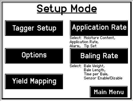
15 Operation of the ISOBUS Monitor Description of Screens and Menus of the ISOBUS Monitor All Buttons are color coded and labeled. Selections can be made by touching the actual screen choice or by touching the numbers down the right side menu which are color and numerically coded to correlate with the same selection. Listed below are the Main Menu Options. Main Menu of the Preservative Applicator Screen Automatic Mode ( 1 ) This operating mode allows the operator to watch the moisture content of crop and keep individual bale records. The following items are displayed in the mode while baling: Moisture, Baling Rate, Last Bale Average Moisture, and Tons Baled. Manual Mode ( 2 ) This operating mode allows the operator to also watch the moisture content of the crop and keep individual records. The following items are displayed in the mode while baling: Moisture, Baling Rate, Last Bale Average Moisture, and Tons Baled. Diagnostics ( 3 ) Allows operator to set the date and time. The installed software versions can also be viewed here. Setup Mode ( 4 ) This mode allows the operator to customize the applicators settings for their baler and baling needs. This mode allows changes to be made to the following areas: Application Rate, Baling Rate, Language, US or Metric units, and turn on/off the optional Hay Indicators. Job Records ( 5 ) Keeps track of up to 300 jobs with total product used, average moisture content, highest moisture content, tons baled, date of baling, and total number of bales made. Individual bales are also able to be viewed and the records can also be downloaded to a USB drive in this mode. 15
 After pushing the AUTOMATIC MODE key in the MAIN MENU screen, the following screen should appear: 3 1 2 4 5 6 1.")
16 Operating Instructions Automatic Mode will be used in the field to read both hay moisture content sensed by the star wheels and the operator s preset parameters to determine baling rate and tons per hour. Automatic Mode (or Manual Mode) After pushing the AUTOMATIC MODE key in the MAIN MENU screen, the following screen should appear: The moisture content is shown in the upper right hand corner (1) 2. Baling Rate and Application Rate (2) are shown in the middle. The application rate will always be zero. The target rate will show a number when the moisture of the hay exceeds the initial set point of 16%. The Baling Rate is calculated in the SETUP MODE. 3. The Graph (3) shows the moisture trend from the past 90 seconds in 3 second intervals. 4. The totals on the bottom of the screen show the total Tons Baled and # Used (4) (pounds of product used) for the current job. These numbers will reset to zero when a new Job Record is started. If operating with Bale Rate Sensors OFF total Tons Baled will be zero. 5. Last Bale (5) shows the average moisture content for the last bale. 6. Press the MAIN MENU (6) key to return to the opening screen. 16


17 The following pages provide additional screen functionality you may choose to use if you add preservative and or the tagging capabilities. Description of Additional Screens and Menus Use the below listed screen menus to navigate through all of the operation screens. Navigation through the screens is accomplished by using the touch screen and pressing the appropriate function. Diagnostics: 17


18 Setup Mode: 18


19 Job Records: 19

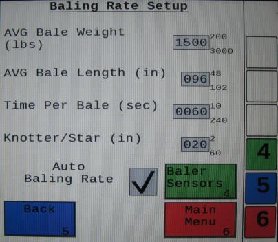
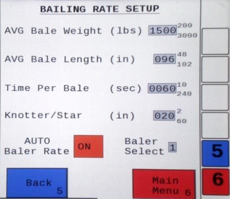
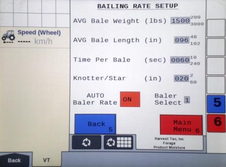
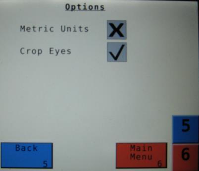
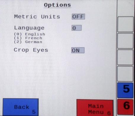
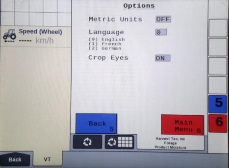
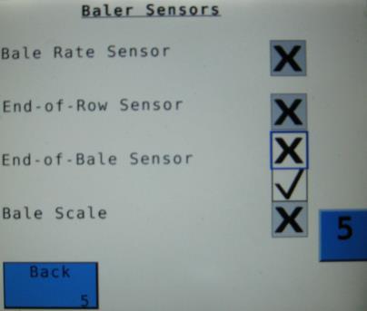
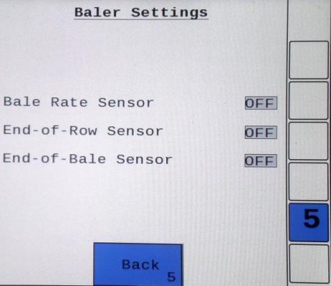
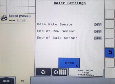
20 Setting Up Bale Parameters for Initial Use In the SETUP MODE you will set your initial baling rate. Baling Rate Setup After pushing the SETUP MODE key in the MAIN MENU screen, the top screen should appear: On this screen the operator will Select the BALING RATE SETUP (1) key. 2. Select the number to the right of AVG Bale Weight (Lbs) (2) : to adjust the weight of your bales. The key pad shown will display. Select any number combination in this screen within the min/max limits. The information will remain until it is changed again. 3. Select the number to the right of AVG Bale Length (In) (3): to adjust the length of your bales. Select any number combination in this screen within the min/max limits. The information will remain until it is changed again. 4. Select the number to the right of Time Per Bale (Sec) (4): to adjust the time it takes to make a bale. Select any number combination in this screen within the min/max limits. The information will remain until it is changed again. 5. Select the number to the right of Knotter/Star (5) to adjust the distance between the knotter and star wheel. To determine the distance, measure between the center of the starwheel and the center of the knotter. This is important so the job record correlates to the bale being made. 6. When the AUTO Bale Rate (6) sensors are ON the applicator will calculate your tons per hour automatically. When the AUTO Bale Rate (6) sensors are OFF a constant tons per hour (your inputed bale weight and time) will be used. Operating the unit with the AUTO Bale Rate sensors OFF will cause total tons per hour in Job Records to be left blank. Select the underlined word to toggle between ON or OFF. First Time and Annual Setup is checking with AUTO Bale Rate sensors OFF. 7. Selecting the Baler Select (7) will allow you to use the baler sensors if your baler is equiped with them from the factory. The baler sensors will come OFF as a default. If you choose to use the baler sensors be sure your baler is equipped with that option. For example, if you do not have an electronic bale length kit, turn the sensor to OFF. The baler End of Row sensors are triggered once the PTO speed goes below 600RPM. The End of Bale sensor is triggered by the tie cycle alarm. The Bale Scale sensor is for the baler equiped with a Chute Scale. Note: Baling on rough terrain or hills can cause the scale to give an inaccurate reading. Turn Bale Scale option OFF in the Bale Rate Screen and use AVG Bale Weight (2) reading as weight of bale. 8. Next select the Back (8) key found on the bottom left hand of the screen to return to the SETUP MODE screen, or select the MAIN MENU (9) key on the bottom right hand of the screen to return to the opening screen. 9. Select the OPTIONS (10) key to adjust the system between metric and standard units. The Crop Eyes can also be turned ON or OFF in the OPTIONS screen. Select the ON/OFF next to Crop Eyes to change this setting. Note: If you change languages youmay need to reset the system from the MAIN MENU screen
 key. In the next screen enter the date (month, day, year format) followed by the time. When done select the OK (2) key.")
21 Operating Instructions for Additional Screens Diagnostics After pressing the DIAGNOSTICS key in the MAIN MENU screen, the screen on the left should appear: To set date and time select the Set Date/Time (1) key. In the next screen enter the date (month, day, year format) followed by the time. When done select the OK (2) key. NOTE: The clock uses military (or 24 hour) time. 2. Select the Software Versions (3) key to check all software versions of modules attached to the Dual Channel Processor (DCP). 3. Press the MAIN MENU (4) key to return to the opening screen. 4
 will save all the previous bale records and open the Field Name (2) screen. 2. Use the key pad in the Field Name screen to enter up to an eight character field name.")
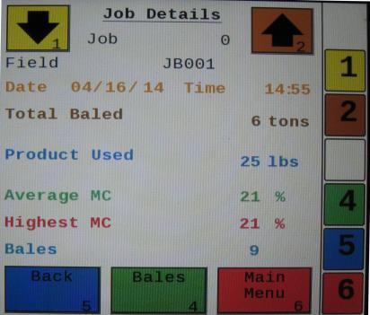
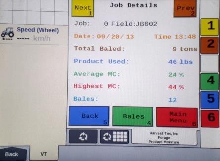
 will open the Job Details screen. Use the Next and Prev (4) icons to view the different jobs. Job: 0 will always be your current and open job record.")
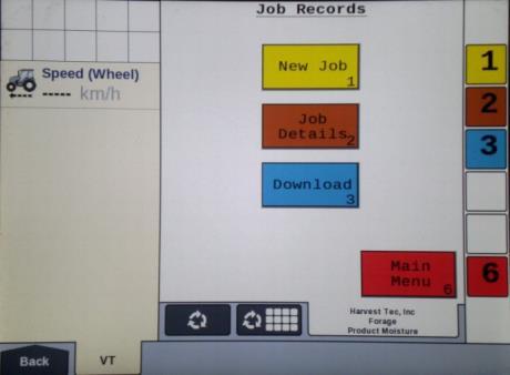
22 Job Records After pushing the JOB RECORDS key in the MAIN MENU screen, the upper left screen below should appear: Selecting New Job (1) will save all the previous bale records and open the Field Name (2) screen. 2. Use the key pad in the Field Name screen to enter up to an eight character field name. Use the asterisk key to move on to the next letter or number if they are identical. Use the pound sign (#) as a space between the characters. When you have completed the field name press enter. 3. Pressing Job Details (3) will open the Job Details screen. Use the Next and Prev (4) icons to view the different jobs. Job: 0 will always be your current and open job record. Press Back (5) to go to the Job Records screen or Main Menu (7) for the main screen. 4. Selecting Bales (6) at the center bottom of the screen will open a Bale Details (7) screen. This screen lets you look at the individual bale records for the first five bales made. Use the Next and Prev icons to scroll through five bales at a time. Select Back (5) to go to the Job Details screen or Main Menu (8) for the main screen. Continued on the next page 22
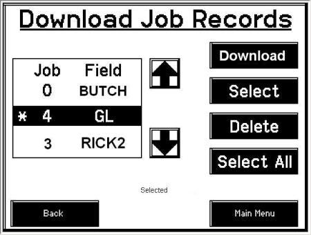
 you would like to download using the Next and Prev (10) icons to highlight the job(s).")
23 Continued Job Records Selecting the Download (9) key will open the Download Job Records screen. This screen lets you select jobs to download onto a USB drive. To download job records insert a USB drive into the port on the Dual Channel Processor. Select the job(s) you would like to download using the Next and Prev (10) icons to highlight the job(s). Once the desired jobs are selected press the Download (9) key. Press the Download key again to confirm. When the USB drive light goes off all the jobs selected will be saved. The jobs can then be opened on any computer with Excel or Notepad. To delete jobs highlight, select them and press Delete (11) followed by pressing Delete again for confirmation. Press Back to go to the Job Records screen or Main Menu for the main screen. 6. Pressing the Select (12) key will select or unselect the highlighted job. 7. Pressing the Select All (13) key will select all jobs, except for the current job (0). To unselect press the Back (14) key. 8. The job record in Excel will show as on the left above. The Bale ID column will need to be adjusted for proper viewing. 9. The job record in Notepad will show as on the right above. You will need to scroll right to see all the information. 23
24 Wiring Diagram A. The Baler Power/Communication Harness ( LS(E)) will attach to the open port of the Tractor Harness ( TM(E)) and run back to the Dual Channel Processor ( LS(E)). B. Connect the large plug of the Baler Power/Communication Harness ( LS) to the bottom (shorter side) of the DCP. Attach the Baler Interface Harness ( VA) in between the short whip cable hardwired to the DCP and the Power/Communication Harness ( LS(E)). C. Make sure Active Terminator removed from the top of the baler processor is attached to the Baler Interface Harness ( VA). D. Attach moisture and bale rate harness ( HL(E)) and also end of bale harness ( BBEXT) to the DCP ( LS(E)). E. Connect Keyed Power Extension harness ( K) to a keyed power source. F. Connect the Bluetooth Receiver ( B) to the Communication Harness ( TM(E)). G. Note: The Optional Port and the Data Transfer Port are not used in this application. Star Wheel Assembly (2X) Proximity Sensor (2X) S Moisture/Bale Rate Harness HL(E) Data Transfer Dual Channel Processor (DCP) LS End of Bale Sensor BB Extension for Bale Sensor BBEXT Optional Port Terminating Connector Z Orange Wire to Keyed Power Bluetooth Receiver B Keyed Power Extension K Baler Connection Baler Interface Harness VA Power/Comm Harness on Baler LS(E) Power/Comm Harness on Tractor TM(E) Active Terminator from Baler Harness 24 *Note: (E) indication is used for International Dealers

 Pin 1")

25 Pin Outs Power/Comm Harness TM(E) at Hitch Pin 1 Red +12V Power to TSD Pin 2 Red +12V Power to DCP Pin 3 Orange Keyed Power Pin 4 Gray Shield Pin 5 Green HT Can Low Pin 6 Yellow HT Can Hi Pin 7 Orange Can1 Hi Pin 8 Black Ground from TSD Pin 9 Black Ground from DCP Pin 10 Blue Can1 Low Power/Comm Harness LS(E) at Hitch Pin 1 Red +12V Power to TSD Pin 2 Red +12V Power to DCP Pin 3 Orange Keyed Power Pin 4 Gray Shield Pin 5 Green HT Can Low Pin 6 Yellow HT Can Hi Pin 7 Orange Can1 Hi Pin 8 Black Ground from TSD Pin 9 Black Ground from DCP Pin 10 Blue Can1 Low Bluetooth Receiver on Harness TM(E) Pin 1 Red +12V Power from DCP Pin 2 Black Ground from TSD Pin 3 Yellow HT Can Low Pin 4 Gray Shield Pin 5 Green HT Can Hi Pin 6 Orange Can1 Hi Pin 7 Blue Can1 Low VA to DCP Whip Pin 1 Red Can Power Pin 2 Black Can Ground Pin 3 Yellow HT Can Hi Pin 4 Gray Shield Pin 5 Green HT Can Low Pin 6 Orange Can1 Hi Pin 7 Blue Can1 Low 25


26 Pin Outs (continued) VA to LS(E) Pin 1 Red Can Power Pin 2 Black Can Ground Pin 3 Yellow HT Can Hi Pin 4 Gray Shield Pin 5 Green HT Can Low Pin 6 N/A Pin 7 N/A VA Harness to Baler Plug Pin A N/A Pin B Red TBC Power Pin C N/A Pin D Gray TBC Ground Pin E Orange Can1 Hi Pin F Blue Can1 Low A D Main Power Connector on DCP Pin 1 Red +12V Power from tractor Pin 2 Black Ground from tractor Pin 3 Orange Keyed power Star Wheel and Bale Rate Sensor Connector on DCP Pin 1 Blue +12V Power Pin 2 Orange Ground Pin 3 Black Signal for sensor 1 Pin 4 White Signal for sensor 2 Pin 5 N/A Pin 6 N/A Pin 7 N/A Pin 8 Violet Star wheel input 1 Pin 9 Brown Star wheel input 2 End of Bale Sensor on DCP Pin 1 Brown Sensor Power Pin 2 Blue Sensor Ground Pin 3 N/A Pin 4 Black Signal from Sensor 26
27 Maintenance If you are unsure how to perform any of the maintenance steps have your local authorized dealer perform the tasks. Dielectric Grease Connections: Disconnect all harnesses on the applicator, clean the connections, and repack with dielectric grease. Battery Connections: Follow the batteries safety warnings and clean the battery connections. If the connections cannot be cleaned, replace harness. Winter Storage 1. Disconnect power from the Dual Channel Processor. 2. Remove display from tractor and store in a warm, dry place. Common Questions 1. How do I turn the system on/off? To turn the system ON open the Hay App, then select the active system for the baler you are using. Press the Wake Up tab if the system was put into Standby mode when last used. If not in Standby mode, select Automatic or Manual mode to begin. To turn the system OFF click the Standby tab on the Main Menu screen. To close the app double click the home button on the ipad and swipe the app that you would like closed, toward the top of the screen until it is no longer visible. See SHUTTING DOWN THE HAY APP for more details. 2. How to get in the LBS/TON, MC%, and TONS/HR screens? In the Main Menu press the SETUP MODE key. From this screen you can change your application rates and how much product is applied. See SETTING UP FOR INITIAL USE for a detailed explanation of this process. 4. The moisture content displays LO or HI all the time. When the moisture content display does not change frequently while baling, there is likely a faulty star wheel connection. Initially check inside the white star wheel block, to see if the electronic swivel is in the star wheel shaft and that the star wheel shaft is not coming out of the block. Also, check all star wheel wires and connectors to see if there is a continuity of grounding problem. 5. Should the battery connections be removed before jump starting or charging a battery? Yes. Anytime the tractor will have voltage going up rapidly the connections should be removed. 6. What is the expected battery life of the ipad when baling? 3.5 hours is the expected amount of time the battery when continuously baling. Shut off all other applications, wireless internet, and Wi-Fi signal to reduce the amount of programs ipad is running. *It is recommended to use an accessory outlet charger when operating (not included with ipad). 7. What is the max distance for connection between the ipad and the Bluetooth Receiver? The range for the connection will depend on the amount of equipment (tractor, baler, ect.) between the two devices. The max distance will range between What do the lights on the B indicate? Blinking Lights System is waiting for the processor to connect, which could take up to 35 seconds. Red Light The Bluetooth receiver has power. Green Light When the proper active connection is selected in the Hay App menu, the green light will indicate connection with the ipad. 27
28 Troubleshooting PROBLEM POSSIBLE CAUSE SOLUTION Moisture reading errors (high or low) 1. Wire disconnected or bad 1. Reconnect wire. connection between star wheels and DCP 2. Low power supply to DCP 2. Check voltage at box. (Min of 12 volts required.) See Diagnostics section of manual. 3. Dry hay lower than 8% 3. System reads 8-70% moisture. moisture or wet hay over 75%. 4. Ground contact with one or 4. Reconnect. both star wheels and baler mounted processor. 5. Short in wire between star 5. Replace wire. wheels and DCP. 6. Check hay with hand tester to verify. 6. Contact Harvest Tec if conditions persist. Moisture readings erratic. 1. Test bales with hand tester to verify that DCP has more variation than hand tester. 2. Check all wiring connections for corrosion or poor contact. 2. Apply dielectric grease to all connections. 3. Check power supply at tractor. Voltage should be constant between 12 and 14 volts. 3. Install voltage surge protection on tractors alternator. Terminal reads under or over power. Bale rate displays zero. Bluetooth Receiver lights will not illuminate 1. Verify with multi-meter actual voltage. Voltage range should be between volts. 1. Bale rate sensors are reversed. 2. Short in cable. 3. Damaged sensor. 4. Sensor too far from starwheel. 1. Bluetooth receiver not connected 2. Harness disconnected 3. Low power 1. Clean connections and make sure applicator is hooked to battery. See Diagnostics section of manual. 1. Switch the sensors next to the star wheel. 2. Replace cable. 3. Replace sensor. 4. Adjust gap between prox sensor and star wheel so it is 1/8-1/4 away. 1. Check connections and voltage. Minimum 12.5V needed. Blinking Lights System is waiting for the processor to connect, which could take up to 35 seconds. Red Light The Bluetooth receiver has power Green Light When the proper active connection is selected in the Hay App menu, the green light will indicate connection with the ipad. 28

 indication is used for International")
29 Parts Breakdown 600BB Series Controls and Harnesses Dual Channel Processor (DCP) Ref Description Part Number Qty 1 End of Bale Sensor 600 Series End of Bale Sensor Bracket Terminating Connector 600 Series w/green cap Z 1 4 DCP Shield/Cover X 1 5 DCP Main Control LS 600 AUTO LS 1 6 DCP Baler Harness 15 FT LS(E) 1 7 DCP Tractor Harness TM(E) 1 8 Dust Plugs PLUGS 1 9 DCP Baler ISO/VT Harness VA 1 10 EOB Extension for CNH BB Series BBEXT 1 11 Key Switch Wire K 1 12 Bluetooth Receiver B 1 12 *Note: (E) indication is used for International Dealers \ 29


30 Parts Breakdown for Star Wheel Moisture Sensor And Bale Rate Sensors Ref Description Part Number Qty Ref Description Part Number Qty 1. Block cover B 2 9. Star wheel block A 2 2. Electronic swivel A Star wheel sensor C 2 3. Swivel insert w/ Ref # Twine guard-left Snap ring (per side) K 2 Twine guard-right (prox) Washer (per side) w/ k 2 And with bale rate sensor 6. Dust seal (per side) w/ k 2 holes in it 7. Plug fitting 003-F Star wheel assembly Wiring grommet A 2 12 Ref Description Part Number Qty 12 Bale rate sensor S 2 13 Moisture and bale rate harness HL(E) 1 13 *Note: (E) indication is used for International Dealers 30
31 Optional ipad Mini Mounting Kit ( MK) Ref Description Part # Qty 1 Suction cup mount SCM 1 2 Ram mount H 1 3 ipad Mini spring load cradle (Mini 1,2,3) SLC gauge power wire P 1 5 Female spade connector Hardware 2 6 Eye loop connector Hardware 2 7 ipad Mini Charger 12V P 1 8 ipad Mini 4 case C4 1 NP 4 amp fuse Hardware 1 Mounting Kit Assembly MK (Includes All Parts) Installation Instructions 1. Identify 12V power source for wires to connect. a. Eye loops included if wiring directly to the battery is desired. b. Test for key power source if preferred to have power to the USB shut off with the key. 2. Once power source is identified, cut wires to desired length. 3. Crimp the two supplied quick connectors onto each the white and black wire. 4. Remove the round locking plastic nut from USB plug before connecting the wires. Black (+) White (-). 5. The wires will then be hooked to the designated terminals on the bottom of the USB plug 6. Drill a 1 1/8 hole in the preferred mounting location. Be sure to clean any sharp edges after drilling. 7. Feed the wires through the mounting hole. 8. If using the round plastic nut to secure plug in place, slide the nut back over the wiring before connecting the wires to powered source. 9. Connect the wires to the identified power source if easier to do so before tightening the plug into place. 10. Tighten plug using either the round plastic nut or mounting plate and two screws, both options supplied. 11. Once connected, hook a USB charging cord into the plug and connect a mobile device/tablet to ensure the plug is operating as you wish (key power working properly if necessary). NOTE: This plug is not designed to charge two ipads. System damage could occur if this is attempted. System will charge a mobile phone and ipad simultaneously without problem. 31
 001-2012SLC 1 9 ipad Mini 4 006-4670IP 1 4 16 gauge power wire 006-4723P 1 NP 4 amp fuse Hardware 1 5 Female")
32 Optional ipad Display Kit ( DK) Ref Description Part # Qty Ref Description Part # Qty 1 Suction cup mount SCM 1 7 ipad Mini Charger 12V P 1 2 Ram mount H 1 8 ipad Mini 4 case C4 1 3 ipad Mini spring load cradle (Mini 1,2,3) SLC 1 9 ipad Mini IP gauge power wire P 1 NP 4 amp fuse Hardware 1 5 Female spade connector Hardware 2 6 Eye loop connector Hardware 2 Mounting Kit Assembly DK (Includes All Parts) Installation Instructions 1. Identify 12V power source for wires to connect. a. Eye loops included if wiring directly to the battery is desired. b. Test for key power source if preferred to have power to the USB shut off with the key. 2. Once power source is identified, cut wires to desired length. 3. Crimp the two supplied quick connectors onto the white and black wire. 4. Remove the round locking plastic nut from USB plug before connecting the wires. Black (+) White (-). 5. The wires will then be hooked to the designated terminals on the bottom of the USB plug 6. Drill a 1 1/8 hole in the preferred mounting location. Be sure to clean any sharp edges after drilling. 7. Feed the wires through the mounting hole. 8. If using the round plastic nut to secure plug in place, slide the nut back over the wiring before connecting the wires to powered source. 9. Connect the wires to the identified power source if easier to do so before tightening the plug into place. 10. Tighten plug using either the round plastic nut or mounting plate and two screws, both options supplied. 11. Once connected, hook a USB charging cord into the plug and connect a mobile device/tablet to ensure the plug is operating as you wish (key power working properly if necessary). NOTE: This plug is not designed to charge two ipads. System damage could occur if this is attempted. System will charge a mobile phone and ipad simultaneously without problem. 32
33 Notes 33
34 Notes 34
35 Harvest Tec Inc. Warranty and Liability Agreement Harvest Tec, Inc. will repair or replace components that are found to be defective within 12 months from the date of manufacture. Under no circumstances does this warranty cover any components which in the opinion of Harvest Tec, Inc. have been subjected to negligent use, misuse, alteration, accident, or if repairs have been made with parts other than those manufactured and obtainable from Harvest Tec, Inc. Our obligation under this warranty is limited to repairing or replacing free of charge to the original purchaser any part that in our judgment shows evidence of defective or improper workmanship, provided the part is returned to Harvest Tec, Inc. within 30 days of the failure. If it is determined that a non-harvest Tec branded hay preservative has been used inside the Harvest Tec applicator system where the failure occurred, then Harvest Tec reserves the right to deny the warranty request at their discretion. Parts must be returned through the selling dealer and distributor, transportation charges prepaid. This warranty shall not be interpreted to render Harvest Tec, Inc. liable for injury or damages of any kind, direct, consequential, or contingent, to persons or property. Furthermore, this warranty does not extend to loss of crop, losses caused by delays or any expense prospective profits or for any other reason. Harvest Tec, Inc. shall not be liable for any recovery greater in amount than the cost or repair of defects in workmanship. There are no warranties, either expressed or implied, of merchantability or fitness for particular purpose intended or fitness for any other reason. This warranty cannot guarantee that existing conditions beyond the control of Harvest Tec, Inc. will not affect our ability to obtain materials or manufacture necessary replacement parts. Harvest Tec, Inc. reserves the right to make design changes, improve design, or change specifications, at any time without any contingent obligation to purchasers of machines and parts previously sold. Revised 4/17 35
36 HARVEST TEC, INC. P.O. BOX HARVEY STREET HUDSON, WI PHONE: FAX:
Operation Manual. Model 300SS. Moisture Only Kit for Small Square Balers 300SS-16-OPR 4/18
 Operation Manual Model 300SS Moisture Only Kit for Small Square Balers 300SS-16-OPR 4/18 1 (intentionally blank) 2 300SS Operation Manual Table of Contents Page Introduction 4 System Requirements 4 Safety
Operation Manual. Model 300RB & 300RBC. Moisture Only Kit for Round Balers 300RB & 300 RBC-16-OPR 4/19
 Operation Manual Model 300RB & 300RBC Moisture Only Kit for Round Balers 300RB & 300 RBC-16-OPR 4/19 1 (intentionally blank) 2 300RB & 300 RBC Operation Manual Table of Contents Page Introduction 4 System
Operation Manual. Model 600RBC. Moisture Sensor Kit for Roll-Belt Round Balers. 600RBC-17-OPR-Imp&Metric 4/19
 Operation Manual Model 600RBC Moisture Sensor Kit for Roll-Belt Round Balers 600RBC-17-OPR-Imp&Metric 4/19 1 DECLARATION OF INCORPORATION MANUFACTURER: Harvest Tec Inc. 2821 Harvey St. P.O. Box 63 Hudson,
Operation Manual. Model 600. Moisture Sensor Kit for Large Square Balers OPR-BLE 5/18
 Operation Manual Model 600 Moisture Sensor Kit for Large Square Balers 600-16-OPR-BLE 5/18 (intentionally blank) 2 Harvest Tec Model 600 Operations Table of Contents Page Introduction 4 Safety 4 Safety
Owner s Manual. Model 6672A. 600 Series ipad Conversion Kit 6672A-16 1/17
 Owner s Manual Model 6672A 600 Series ipad Conversion Kit 6672A-16 1/17 Harvest Tec 6672A Table of Contents Page Introduction 3 Installation of Bluetooth Receiver 3-6 Large Square Baler Power Cable and
Owner s Manual. Model 6672B. 600 Series ipad Conversion Kit. 6672B-17-Imp&Metric 5/19
 Owner s Manual Model 6672B 600 Series ipad Conversion Kit 6672B-17-Imp&Metric 5/19 DECLARATION OF INCORPORATION MANUFACTURER: Harvest Tec Inc. 2821 Harvey St. P.O. Box 63 Hudson, WI 54016, U.S.A. REPRESENTATIVE
Operation Manual. MODEL 647, 647C & & 55 Gallon Automatic Preservative Applicators C OPR-BLE 4/19
 Operation Manual MODEL 647, 647C & 649 5 & 55 Gallon Automatic Preservative Applicators 647-647C-649-6-OPR-BLE 4/9 (intentionally blank) Harvest Tec 647, 647C & 649 Operation Table of Contents Page Introduction
Operation Manual. MODEL 647, 647C & 649-M 25 & 55 Gallon Automatic Preservative Applicators C M-OPR-BLE 1/17
 Operation Manual MODEL 647, 647C & 649-M 5 & 55 Gallon Automatic Preservative Applicators 647-647C-649-6-M-OPR-BLE /7 DECLARATION OF INCORPORATION MANUFACTURER: Harvest Tec Inc. 8 Harvey St. P.O. Box 6
OPERATOR S MANUAL. Safety Notices... 1
 Safety Notices... 1 System Overview... 3 Features... 3 System Requirements... 3 Daisy Chain Sensors... 4 Daisy Chain Module(s)... 4 Daisy Chain Module Harnesses 1 and 2 Loop... 4 Module Extension Harnesses...
Safety Notices Tramline Setup Setup Input Type Input State (Hi/Lo) Assigning Sensors Auxiliary Power...
 Assigning Sensors Auxiliary Power...") Safety Notices... 1 System Overview... 3 Features... 3 System Requirements... 3 Daisy Chain Sensors... 4 Daisy Chain Module(s)... 4 Daisy chain Module Harnesses 1 and 2 Loop... 4 Module Extension Harnesses...
Safety Notices... 1 System Overview... 3 Features... 3 System Requirements... 3 Daisy Chain Sensors... 4 Daisy Chain Module(s)... 4 Daisy chain Module Harnesses 1 and 2 Loop... 4 Module Extension Harnesses...
Chore-Tronics Mobile Server
 Chore-Tronics Mobile Server Installation & Operator s Instruction Manual Contact your nearby Chore-Time distributor or representative for additional parts and information. Chore-Time Group A division of
Secured Series: Hub Plus Kit Single Door Controller Package Installation Manual
 Secured Series: Hub Plus Kit Single Door Controller Package Installation Manual This package is designed to simplify the connections to our Secured Series Hub Plus Controller. This will translate into
Ag Leader Technology. DirectCommand Installation Hardi 20-pin Interface Kit (Sprayer Chassis Mount)
") Part Name / Description Part Number Quantity DirectCommand Hardi Sprayer Kit 4100882 1 Dust Receptacle 8-pin 2002975-8C 1 Installation Instructions 2006335 1 Quick Reference Card- Liquid Application 2002831-38
Part Name / Description Part Number Quantity DirectCommand Hardi Sprayer Kit 4100882 1 Dust Receptacle 8-pin 2002975-8C 1 Installation Instructions 2006335 1 Quick Reference Card- Liquid Application 2002831-38
Data Reporter. Installation-Operation E rev.f
 Installation-Operation Data Reporter 309867E rev.f Important Safety Instructions Read all warnings and instructions in this manual. Save these instructions. Part No. 246085 Records actual temperature,
Cab Box Kit Dome Plug Cab Box Cab Box Lid
 DirectCommand Installation Ag Leader Technology Note: Indented items indicate parts included in an assembly listed above Part Name/Description Part Number Quantity Direct Command Kit 4100578 1 Cable Installation
Kodiak Mobile INTELLIGENT DOCKING STATION USERS MANUAL PART NUMBER: PANASONIC CF53 TOUGHBOOK COMPATIBLE AN ISO 9001:2008 CERTIFIED COMPANY
 CUSTOMER SERVICE If you have any questions or require additional information please contact Customer Service at 877-455-6886, Monday though Friday, 8:00am - 5:00pm CST. TECHNICAL SUPPORT Kodiak Mobile
Progressive Industries, Inc. EMS Electrical Management System
 Progressive Industries, Inc. EMS Electrical Management System Complete Installation Guide and Operating Instructions for: Model EMS-LCHW50 Rated at 240V/50A Manufactured by: Progressive Industries, Inc.
INSTALLATION INSTRUCTIONS
 TT-40 9/0 INSTALLATION INSTRUCTIONS Original Issue Date: 9/0 Model: Automatic Transfer Switches Equipped with the Programmable Controller Market: ATS Subject: External Battery Supply Module Kit GM69-KP
OWNER S MANUAL Calc-U-Dri PRINTER
 OWNER S MANUAL Calc-U-Dri PRINTER PNEG-1141 Date: 9-21-06 PNEG-1141 Calc-U-Dri Printer TABLE OF CONTENTS Limited Warranty... ii Safety Information - Please Read...iii CAUTION! Be a Safe Operator...iv Decal
What s in the Box? REAR VIEW SAFETY
 TM 1 What s in the Box? 1 Full HD Color Infra-red Weather Proof Camera 1 Full HD 7" TFT LCD Color Monitor w/monitor Mount 1 Power Harness 1 66 Camera Cable 1 Power Connection Wire 1 Screw Kit for installation
Ag Leader Technology. DirectCommand Installation Miller Nitro 5000 & 6000 ISO Kit
 Note: Indented items indicate parts included in an assembly listed above Part Name/Description Part Number Quantity Direct Command Miller N5/5000 Series Kit 4200179 1 Installation Instructions 2006382
DirectCommand Installation RoGator Model Year Ag Leader Technology
 Note: Indented items indicate parts included in an assembly listed above Part Name/Description Part Number Quantity Direct Command Kit 4100801 1 Dual Lock 2000052-9 1 Dual Lock 2000053-9 1 Quick Reference
DirectCommand Installation DirectCommand Complete Wiring Harness
 Note: Indented items indicate parts included in an assembly listed above Part Name/Description Part Number With Switch Box Quantity by Model With Boom Switch Cable Display Cable Kit 4100814 1 1 Power Control
Tile Plow Installation O Connell
 NOTE: Indented items indicate parts included in an assembly listed above Part Name/Description Part Number Quantity Tile Plow Kit O Connell System 4100471 1 Hex head cap screw 3/8-16 x 3 2002003-38300
INTELLIGENT DOCKING STATION USERS MANUAL
 Kodiak Mobile by Jotto Desk 209 W. Easy St., Rogers, AR USA 72756 Customer Service: 877.455.6886 http://www.kodiakmobile.com PART NUMBER: 450-4011 - Last Update: 06.2009 INTELLIGENT DOCKING STATION USERS
Note: These installation instructions are only for the 4430/4440 Sprayer. For other SPX models please refer to P/N , &
 DirectCommand Installation Ag Leader Technology Note: These installation instructions are only for the 4430/4440 Sprayer. For other SPX models please refer to P/N 2005944, 2005945 & 2006383. Part Name/Description
SERVICE MANUAL MODEL SSW-521-D2-ADA
 SSW-521-D2-ADA-SPK1.07UNVLr3-ADA-ISSUE4.0 SERVICE MANUAL FOR MODEL SSW-521-D2-ADA STAINLESS STEEL HANDS FREE WALL TELEPHONE WITH OPTIONAL ADA FEATURE AND OPTIONAL SECOND-NUMBER AUTO-DIAL FEATURE EQUIPPED
ipad Charge & Sync Cart Model MCC2 ipad Cart 430-MCC2-User Manual-010 Is a Registered Trademark of Apple Inc. ipad
 ipad Charge & Sync Cart Model MCC2 ipad Cart ipad Is a Registered Trademark of Apple Inc. 430-MCC2-User Manual-010 1. ipad Cart Specifications MCC2 Mobile Charge & Sync Cart Extra Drawer Reserved space
DirectCommand Installation 5 Channel Spreader Control Module Technology
 DirectCommand Installation Ag Leader Technology Note: Indented items indicate parts included in an assembly listed above Part Name/Description Part Number Quantity Direct Command Kit 4100582 1 Cable Installation
CHAPTER 3B: ELECTRONIC POWER STEERING
 Electronic Power Steering CHAPTER 3B: ELECTRONIC POWER STEERING NOTE: The basic steering system, such as the tie rod ends, drag links axles, etc., is covered in Chapter 3A: Steering. In 2012, Cub Cadet
VM VM
 2018 VM-5200-16 VM-5200-32 Operator s Manual The Daugherty Companies, Inc. P.O. Box 306 Warren, IN 46792 Ph. 260-375-2415 - Fax 260-375-3800 www.ag-electronics.com Rev 0418.1 NOTES: 2 Introduction Rev
QuickTouch (QT4) Owner s Manual
 Owner s Manual") QuickTouch (QT4) Owner s Manual 4-Function Hand-Held Wireless Remote Control IMPORTANT SAFETY INSTRUCTIONS READ AND FOLLOW ALL INSTRUCTIONS SAVE THESE INSTRUCTIONS Table of Contents SECTION I. APPLICATION...
QuickTouch (QT4) Owner s Manual 4-Function Hand-Held Wireless Remote Control IMPORTANT SAFETY INSTRUCTIONS READ AND FOLLOW ALL INSTRUCTIONS SAVE THESE INSTRUCTIONS Table of Contents SECTION I. APPLICATION...
Ag Leader Technology Insight. Direct Command Installation Spra-Coupe 7000 Series
 Note: Indented items indicate parts included in an assembly listed above. Part Name / Description Part Number Quantity Direct Command Spra-Coupe 7000 Kit 4100531 1 Liquid Product Control Module 4000394
Flex Pro Series Assembly Guide
 ELECTRIC HEIGHT-ADJUSTED SIT TO STAND DESK Table of Contents CAUTION, USE & LIABILITY... 2 PARTS & HARDWARE LIST... 3 PARTS / COMPONENT DIAGRAMS... 3 ASSEMBLY INSTRUCTIONS... 5 BLUETOOTH... 10 TROUBLESHOOTING...
SERVICE MANUAL MODEL SSC-301-F (FORMERLY 301-FS) MODEL BLC-301-F (FORMERLY 301-F)
 MODEL BLC-301-F (FORMERLY 301-F)") SSC-301-F OR BLC-301-F-ISSUE4.0 SERVICE MANUAL FOR MODEL SSC-301-F (FORMERLY 301-FS) OR MODEL BLC-301-F (FORMERLY 301-F) CHARGE-A-CALL TELEPHONE Serving the Telephone Industry Since 1930 Communication
SSC-301-F OR BLC-301-F-ISSUE4.0 SERVICE MANUAL FOR MODEL SSC-301-F (FORMERLY 301-FS) OR MODEL BLC-301-F (FORMERLY 301-F) CHARGE-A-CALL TELEPHONE Serving the Telephone Industry Since 1930 Communication
Part Name/Description Part Number Quantity
 Part Name/Description Part Number Quantity Direct Command 4200159 1 Cable Installation Kit 2000901-1 1 Hood 37-pin DSub 2001808-37 2 Dielectric Grease 2002872 1 Dust Plug 12 Pin Gray 2002899-12N 1 Feature
What s in the box. SUP paddle sensor. Paddle sensor mounting track. Charger. USB cable. In your Motionize SUP kit you will find:
 User's Manual 1 What s in the box In your Motionize SUP kit you will find: SUP paddle sensor Paddle sensor mounting track Charger USB cable 2 Android & ios Requirements Android 5 or newer. iphone 5 or
Tracer VM Bluetooth Interface
 Tracer Bluetooth Interface Model number BTI-102 Operating Instructions General The Bluetooth Interface collects, transmits and saves data from Base Flowmeters installed in injection mold cooling circuits.
GENERAL DESCRIPTION... 1 INSTALLATION... 2 CONNECTIONS... 3 OVERVIEW... 6 AREA & SPEED METER SETUP (WIZARD)... 9
... 9") TABLE OF CONTENTS For Serial Numbers 30007000-7999 GENERAL DESCRIPTION... 1 INSTALLATION... 2 CONNECTIONS... 3 OVERVIEW... 6 AREA & SPEED METER SETUP (WIZARD)... 9 AREA & SPEED METER USING GPS SETUP (WIZARD)...
TABLE OF CONTENTS For Serial Numbers 30007000-7999 GENERAL DESCRIPTION... 1 INSTALLATION... 2 CONNECTIONS... 3 OVERVIEW... 6 AREA & SPEED METER SETUP (WIZARD)... 9 AREA & SPEED METER USING GPS SETUP (WIZARD)...
Interface Module for radio Auxiliary Input. Installation & Operation
 Interface Module for radio Auxiliary Input Installation & Operation Serial Number: Date of Purchase: Contents Introduction and Precautions... 2 Supported ipod Models... 3 Installation...3-4 Operation...
Owner s Manual. TSD-DCPDV DC Power Distribution with Fixed & Variable Outputs. TSD-DCPDV DC Power Distribution. AtlasIED.com
 Owner s Manual with Fixed & Variable Outputs 1 AtlasIED.com Owner s Manual Description The AtlasIED Variable Block is designed to reduce cost and wiring clutter in installations where multiple DC power
PWRguard PLUS Spring City Drive Waukesha, WI
 PWRguard PLUS www.westmountainradio.com 1020 Spring City Drive Waukesha, WI 53186 262-522-6503 sales@westmountainradio.com 2016, All rights reserved. All trademarks are the property of their respective
Hi-Tech Transport Electronics, Inc. DUAL LEVELING VALVE PROCESSOR INSTALLATION MANUAL. For the 4600 Scale System For the 5600 Scale System
 Hi-Tech Transport Electronics, Inc. DUAL LEVELING VALVE PROCESSOR INSTALLATION MANUAL For the 4600 Scale System For the 5600 Scale System September 1999 THE ACCURATE ON-BOARD ELECTRONIC SCALE For Air-Ride
DirectCommand Installation CASE IH SPX Ag Leader Technology. PN: Rev. E January 2014 Page 1 of 19
 Note: These installation instructions only cover installation on SPX 4420 Sprayers only. For installation on SPX 3230/3330 Sprayers refer to Installation Instructions P/N 2005945. For SPX 4430 refer to
Illuminate 25 Light Starter Kit What s included Light String Control Box Spare Fuses Safety Instructions Quick Start Guide
 Illuminate Password: 12345678 QR Codes to download App: IOS/Apple Android Quick Start Guide Illuminate 25 Light Starter Kit What s included Light String Control Box Spare Fuses Safety Instructions Quick
EMS. Electrical Management System. Progressive Industries Incorporated Morrisville, North Carolina
 Progressive Industries Warranty Progressive warrants its products are free from defects in materials and workmanship for a period of three years. This is in lieu of all other warranties, obligations, or
RAM Rail Mount Kit RAM 201U 5 Arm RAM 2461U Monitor Mount RAM 235U Base, Double U-Bolt
 DirectCommand Installation Ag Leader Technology Note: Indented items indicate parts included in an assembly listed above Part Name/Description Part Number Quantity DirectCommand Kit 4100852 1 Cable Installation
7" Touch Screen Display
 7" Touch Screen Display Installation Guide Contents Minimum Requirements...1 Select a Location...1 Initial Setup...2 Unboxing...2 Installation...3 Prepare the Panel...3 Install the Mounting Plate...3 Mount
RESIDENTIAL OPERATOR MOTOR CONTROL BOARD REPLACEMENT INSTRUCTIONS
 READ THIS MANUAL CAREFULLY BEFORE BEGINNING INSTALLATION RESIDENTIAL OPERATOR MOTOR CONTROL BOARD REPLACEMENT INSTRUCTIONS PRODUCT FEATURES MODELS: IIA SPRINT 310/510/710 200/250 2000 SERIES 3000 SERIES
Electrical Management System (EMS) EMS-HW30C & EMS-HW50C
 EMS-HW30C & EMS-HW50C") Electrical Management System (EMS) EMS-HW30C & EMS-HW50C Installation & Operating Guide for: Model EMS-HW30C Rated at 120V/30A and Model EMS-HW50C Rated at 240V/50A Surgio Says Lifetime Warranty on all
Electrical Management System (EMS) EMS-HW30C & EMS-HW50C Installation & Operating Guide for: Model EMS-HW30C Rated at 120V/30A and Model EMS-HW50C Rated at 240V/50A Surgio Says Lifetime Warranty on all
4200-DL Model # C-4200-DL DL Controller Instruction Manual V.1.0. This instruction manual serves as a guide for the 4200-DL Controller.
 4200-DL Controller Instruction Manual V.1.0 4200-DL Model # C-4200-DL This instruction manual serves as a guide for the 4200-DL Controller. IMPORTANT! Please read through all provided instructions and
SERVICE MANUAL MODEL SSP-363-E (FORMERLY SSP-365-E)
") SSP-363-E-(SSP-365-E)-ADT1.03-ISSUE4.0 SERVICE MANUAL FOR MODEL SSP-363-E (FORMERLY SSP-365-E) STAINLESS STEEL PANEL TELEPHONE WITH 12 BUTTON AUTOMATIC DIALER EQUIPPED WITH ADT1.03 FIRMWARE Serving the
SSP-363-E-(SSP-365-E)-ADT1.03-ISSUE4.0 SERVICE MANUAL FOR MODEL SSP-363-E (FORMERLY SSP-365-E) STAINLESS STEEL PANEL TELEPHONE WITH 12 BUTTON AUTOMATIC DIALER EQUIPPED WITH ADT1.03 FIRMWARE Serving the
INSTALLATION INSTRUCTIONS
 Distributed By: INSTALLATION INSTRUCTIONS Product Revision Form Rev. H PANASONIC CF19 DOCKING STATIONS, CRADLE and ACCESSORIES 7160-0207: Docking Station (NO/RF) 7160-0215: LED Assembly 7160-0207-02: Docking
INSTALLATION INSTRUCTIONS
 INSTALLATION INSTRUCTIONS 3YEAR WARRANTY & LIMITATION OF LIABILITY TRI-TRONICS COMPANY, INC. warrants that the products delivered by it will be of the kind and quality described in the order or contract
I/O Expansion Box Installation & Operator s Instruction Manual
 I/O Expansion Box Installation & Operator s Instruction Manual May 2004 CTB Inc. Warranty I/O Expansion Box CTB Inc. Warranty CTB Inc. warrants each new Chore-Tronics product manufactured by it to be free
Elapsed Timer Control Panel
 Installation Manual V6.2 Elapsed Timer Control Panel Current as of August 2017 The Sapling Company, Inc. Elapsed Timer Control Panel Table of Contents Table of Contents 2 Important Safety Instructions
MK-MANTA III OWNER S MANUAL PARTS LIST & OPERATING INSTRUCTIONS
 www.mkdiamond.com MK-MANTA III OWNER S MANUAL PARTS LIST & OPERATING INSTRUCTIONS Revision 202 08.2012 Manual Part# 161117 Caution: Read all safety and operating instructions before using this equipment.
Tile Plow Installation Gold Digger
 NOTE: Indented items indicate parts included in an assembly listed above Part Name/Description Part Number Quantity Tile Plow Kit Soil Max System 4100470 1 Hex head cap screw - M10 x 75mm 2002007-10075
EMS Electrical Management System
 EMS Electrical Management System Complete Installation/Operating & Warranty Guide EMS-HW50C Rated at 240 Volts/50 Amps Manufactured & Warranted by Progressive Industries Sold & Serviced by VIP Enterprises
CF3000 Dealer Diagnostic Tool Instruction Manual
 CF3000 Dealer Diagnostic Tool Instruction Manual Table of Contents: About the CF3000......3 Important Precautions......4 Components....5 Charging the CF3000......7 Licensing the CF3000.......8 Updating
Ag Leader Technology. DirectCommand Installation RoGator Model Years
 Note: Indented items indicate parts included in an assembly listed above Part Name/Description Part Number Quantity Direct Command Kit 4100550 1 Dual Lock 2000052-9 1 Dual Lock 2000053-9 1 Hardware Kit
User Guide. Model Temperature Datalogger Kit Model Temperature and Humidity Datalogger Kit Model SW276 Datalogging Software SW276
 User Guide Model 42265 Temperature Datalogger Kit Model 42275 Temperature and Humidity Datalogger Kit Model SW276 Datalogging Software SW276 Introduction Congratulations on your purchase of Extech Instrument
User's Guide Video Borescope Model BR200
 User's Guide Video Borescope Model BR200 Introduction Congratulations on your purchase of this Extech BR200 Video Borescope. This instrument was designed for use as a remote inspection device. It can be
RAM Rail Mount Kit RAM 201U 5 Arm RAM 2461U Monitor Mount RAM 235U Base, Double U-Bolt
 Note: Indented items indicate parts included in an assembly listed above Part Name/Description Part Number Quantity DirectCommand Kit 4100800 1 Cable Installation Kit 2000901-1 1 Dielectric Grease 2002872
24/7 Sprinkler Monitor. The Ultimate Rain/Freeze Sensor
 24/7 Sprinkler Monitor The Ultimate Rain/Freeze Sensor User s Manual PIONEER SALES, LTD. 5529 Redfield St. Dallas, TX 75235 Phone: (214) 276-0306 Fax: (214) 631-4218 Toll Free: 1-(866) 501-7745 1 Table
Pulse LED Instruction Guide
 PARTS LIST Light Fixture Aquarium Frame Mounts Instruction Guide WARNING: To guard against injury, basic precautions should be observed, including the following: A) READ AND FOLLOW ALL SAFETY INSTRUCTIONS.
Dear Customer, User Memo: Please visit us on facebook or twitter! Thank you for purchasing this product.
 Dear Customer, Thank you for purchasing this product. For optimum performance and safety, please read these instructions carefully. User Memo: Date of purchase: Dealer name: Dealer address: Dealer website:
4200 Model # - C Controller Instruction Manual V.3.1. This instruction manual serves as a guide for the 4200 Controller.
 4200 Controller Instruction Manual V.3.1 4200 Model # - C-4200 This instruction manual serves as a guide for the 4200 Controller. IMPORTANT! Please read through all provided instructions and any listed
User Guide. Control Box. RoscoLED TM.
 RoscoLED TM Control Box User Guide This guide applies to the following RoscoLED Control Box models: RoscoLED Control Box 300W/Static White (293 22250 0000) RoscoLED Control Box 400W/VariWhite (293 22260
R52 Top Commander. Installation and Configuration Guide. 325 Sharon Park Dr. #652. Menlo Park, CA USA (650)
") R52 Top Commander Installation and Configuration Guide 325 Sharon Park Dr. #652 Menlo Park, CA 94025 USA (650) 241-1161 www.fes-auto.com R52 Top Commander Installation Guide Page 2 Table of Contents Chapter
R52 Top Commander Installation and Configuration Guide 325 Sharon Park Dr. #652 Menlo Park, CA 94025 USA (650) 241-1161 www.fes-auto.com R52 Top Commander Installation Guide Page 2 Table of Contents Chapter
Zonit μats TM Users Guide μats1-lv Version 1.2
 Zonit μats TM Users Guide μats1-lv Version 1.2 Table of Contents Product Overview...2 Pre-Installation Considerations...2 Product Features...3 Installation...4 Optional Accessories...4 μats TM Operational
INSTALLATION INSTRUCTIONS 5" SINGLE CHANNEL ULTIMATE TACH
 Instr. No. 2650-887C INSTALLATION INSTRUCTIONS 5" SINGLE CHANNEL ULTIMATE TACH MODEL 6871, 6872, 6873, 6874, 6875, 6877 IMPORTANT WEAR SAFETY GLASSES 5 4 6 COPYRIGHT PATENT PENDING 3 7 8 PLAYBACK 9 2 0
INSTRUCTION MANUAL. Model True RMS AC/DC 30A Mini Clamp-on Meter. Introduction. True RMS AC Current and Voltage
 INSTRUCTION MANUAL Model 380942 True RMS AC/DC 30A Mini Clamp-on Meter True RMS AC Current and Voltage Measure low current with high resolution to 0.1mA AC and 1mA DC Auto Power Off One touch DCA zero
Adjustable Timing Control PN 8680
 Adjustable Timing Control PN 8680 ONLINE PRODUCT REGISTRATION: Register your MSD product online and you ll be entered in our monthly 8.5mm Super Conductor Spark Plug Wire give-away! Registering your product
ipod /iphone Audio/Video Dock with Remote Control DX-IPDR3 USER GUIDE
 ipod /iphone Audio/Video Dock with Remote Control DX-IPDR3 USER GUIDE 2 ipod /iphone Audio/Video Dock with Remote Control Dynex DX-IPDR3 ipod /iphone Audio/Video Dock with Remote Control Contents Important
FA-2448 SIX POSITION Filter Wheel
 15 Discovery Way, Acton, MA 01720 Phone: (978)263-3584, Fax: (978)263-5086 Web Site: www.acton-research.com Operating Instructions Acton Research Corporation FA-2448 SIX POSITION Filter Wheel Rev. 3.05.17
B&W RearView Camera Installation & Operation
 B&W RearView Camera Installation & Operation CA52 (Camera) FOR MORE INFORMATION WWW.STRATEGICVISTA.COM BEFORE OPERATING THIS SYSTEM, PLEASE READ THIS MANUAL THOROUGHLY AND RETAIN IT FOR FUTURE REFERENCE
Part Name/Description Part Number Quantity
 Part Name/Description Part Number Quantity Direct Command Kit 4100883 1 Installation Instructions 2006336 1 Hardware Kit Large Module 2001354-1 2 Cable Installation Kit 2000901-1 1 Quick Reference Card
Temperature & Humidity Datalogger
 R6030 Temperature & Humidity Datalogger Instruction Manual Table of Contents Introduction... 2 Product Quality... 3 Safety... 3 Features... 3 Included... 3 Specifications... 4 Instrument Description...
Broadband Automatic Disconnect Switch. User Manual
 Reset/Test Primary/ Primary Broadband Automatic Disconnect Switch User Manual Local Power Remote Pwer Local 63V Fault Secondary Select Secondary 220V Normal 990-1929 09/2004 Introduction Introduction
Automatic Phone-Out Home Monitoring System
 Automatic Phone-Out Home Monitoring System Freeze Alarm Model Number: THP217 Product Description This product is intended to monitor homes, cabins, and other premises for low temperature conditions. It
SERVICE MANUAL MODEL SSC-303-F (FORMERLY 303-FS)
") SSC-303-F-650-521-CAC6.00-ISSUE4.1 SERVICE MANUAL FOR MODEL SSC-303-F (FORMERLY 303-FS) CHARGE-A-CALL TELEPHONE EQUIPPED WITH CAC6.00 FIRMWARE Serving the Telephone Industry Since 1930 Communication Equipment
SSC-303-F-650-521-CAC6.00-ISSUE4.1 SERVICE MANUAL FOR MODEL SSC-303-F (FORMERLY 303-FS) CHARGE-A-CALL TELEPHONE EQUIPPED WITH CAC6.00 FIRMWARE Serving the Telephone Industry Since 1930 Communication Equipment
FULL HD DUAL DASH CAM DVR
 USER MANUAL NCP-DVRT1 FULL HD DUAL DASH CAM DVR WITH REVERSE CAMERA & REVERSE MONITOR 2 Caution... 4 Battery warning... 4 Notes on Installation... 4 1 Introduction... 5 1.1 Features... 5 1.2 Package Contents...
INSTRUCTION MANUAL ATTENTION. 1-Year Limited Hardware Warranty
 INSTRUCTION MANUAL INTERMATIC MULTIPURPOSE CONTROL MECHANISM MODEL: P1353ME ATTENTION READ CAREFULLY BEFORE ATTEMPTING TO INSTALL YOUR INTERMATIC MULTIFUNCTION CONTROL SWITCH. FAILURE TO COMPLY WITH INSTRUCTIONS
M2 OLED Temperature Monitor Instructions PN 1841
 M2 OLED Temperature Monitor Instructions PN 1841 Installation Checklist Check for components included Read Warning and Cautions Read page 3 for mounting instructions Read System Overview, Mounting Considerations,
Introduction & Features. Important Notes. Installation Steps
 Navigation Unlock & Reverse Camera Input Interface for Chrysler/Dodge/Jeep/Ram Vehicles Rev. 051915 ***Only applicable to revision 1.1.2 firmware on BCI-CH21*** Class 2 J1850 VPW Arbitration J1850 Class
LA600WH WIRED / WIRELESS DOOR CHIME
 LA600WH WIRED / WIRELESS DOOR CHIME To register this product, visit: www.nutone.com THIS PACKAGE INCLUDES: Wired / Wireless Door Chime with MP3 upload capability Decorative White Chime Cover USB Cable
232iLM Keypad Installation and Programming Instructions
 232iLM Keypad Installation and Programming Instructions Note: This product is designed to be installed and serviced by security and lock industry professionals. Specifications Case Dimensions: 6 1 / 2
SERVICE MANUAL MODEL SSW-521-F (FORMERLY SSW-521-FS)
") SSW-521-F-SPK1.07UNVL-ADA-ISSUE4.0 SERVICE MANUAL FOR MODEL SSW-521-F (FORMERLY SSW-521-FS) STAINLESS STEEL HANDS FREE WALL TELEPHONE OPTIONAL ADA FEATURE AVAILABLE EQUIPPED WITH SPK1.07UNVL FIRMWARE Serving
SSW-521-F-SPK1.07UNVL-ADA-ISSUE4.0 SERVICE MANUAL FOR MODEL SSW-521-F (FORMERLY SSW-521-FS) STAINLESS STEEL HANDS FREE WALL TELEPHONE OPTIONAL ADA FEATURE AVAILABLE EQUIPPED WITH SPK1.07UNVL FIRMWARE Serving
Scrolling USER MANUAL REMOTE CONTROL LED SIGN BOARD. *For 3Color Signs. QWERTY Keypad! / Effects Table / Button Functions / Trouble Shooting Guide NEW
 Scrolling REMOTE CONTROL LED SIGN BOARD USER MANUAL *For 3Color Signs NEW QWERTY Keypad! / Effects Table / Button Functions / Trouble Shooting Guide Table of Contents Components List ---------------------------------------------------------
INSTALLATION MANUAL. Agra-GPS Versatile-JD Bridge (row crop tractor)
") INSTALLATION MANUAL Agra-GPS Versatile-JD Bridge (row crop tractor) Version 1.0 Revision A December 2017 Contact information Agra-GPS Ltd. Box 2585 Stony Plain, AB T7Z 1X9 CANADA 001 780 990 4052 Phone
INSTALLATION MANUAL Agra-GPS Versatile-JD Bridge (row crop tractor) Version 1.0 Revision A December 2017 Contact information Agra-GPS Ltd. Box 2585 Stony Plain, AB T7Z 1X9 CANADA 001 780 990 4052 Phone
RV LEVELING SYSTEM AUTO LEVEL SYSTEM WARNING! FAILURE TO ACT IN ACCORDANCE WITH THE FOLLOWING MAY RESULT IN SERIOUS PERSONAL INJURY OR DEATH.
 RV LEVELING SYSTEM AUTO LEVEL SYSTEM WARNING! FAILURE TO ACT IN ACCORDANCE WITH THE FOLLOWING MAY RESULT IN SERIOUS PERSONAL INJURY OR DEATH. THE USE OF THE GROUND CONTROL AUTO LEVELING SYSTEM TO SUPPORT
ATTENTION. Custom Dynamics CCM-6 Bluetooth Remote Installation Instructions. Package Contents: - Bluetooth Remote Module (1) - Remote Key Fob (2)
 - Remote Key Fob (2)") Custom Dynamics CCM-6 Bluetooth Remote Installation Instructions We thank you for purchasing the Custom Dynamics CCM-6 Bluetooth Remote Module. Our products utilize the latest technology and high quality
Custom Dynamics CCM-6 Bluetooth Remote Installation Instructions We thank you for purchasing the Custom Dynamics CCM-6 Bluetooth Remote Module. Our products utilize the latest technology and high quality
Instruction Manual for Video OSD Expander Document Version 1.4
 Instruction Manual for Video OSD Expander Document Version 1.4 Thank you for your purchase! This instruction manual will guide you through the installation and operation of your Video OSD Expander (the
MOBILE DIGITAL VIDEO RECORDER OPERATING MANUAL EYE COMMUNCATION SYSTEMS, INC. 455 E. INDUSTRIAL DRIVE P.O. BOX 620 HARTLAND, WI 53029
 MOBILE DIGITAL VIDEO RECORDER OPERATING MANUAL EYE COMMUNCATION SYSTEMS, INC. 455 E. INDUSTRIAL DRIVE P.O. BOX 620 HARTLAND, WI 53029 1-800-558-2153 TABLE OF CONTENTS Page Numbers Parts & Components Reference
GSMR30 OWNER S MANUAL
 GSMR30 OWNER S MANUAL Version 1.0 MP4/MP3/Photo Playback Gauge Series Marine Radio FEATURES 4 Channel Full Range, Class A/B 45W x 4 @ 4Ω IPX5 Water proof INPUTS AND OUTPUTS Bluetooth Audio Streaming Easy
EMS Electrical Management System
 EMS Electrical Management System Complete Installation/Operating & Warranty Guide EMS-LCHW30C Rated at 120 Volts/30 Amps Manufactured & Warranted by Progressive Industries Sold & Serviced by VIP Enterprises
SERVICE MANUAL MODEL SSW-321-F MODEL BLW-321-F
 SSW-321-F OR BLW-321-F-ISSUE4.0 SERVICE MANUAL FOR MODEL SSW-321-F OR MODEL BLW-321-F MINI WALL TELEPHONE Serving the Telephone Industry Since 1930 Communication Equipment 519 W South Park Street & Engineering
Adjustable Timing Control PN 8680
 Adjustable Timing Control PN 8680 IMPORTANT: Read the instructions before attempting installation. Parts Included: 1 - Timing Control, PN 8680 1 - Control Knob 1-3/8" Bushing 1-2-Pin Weathertight Connector
Bird Scale Control Installation & Operator s Instruction Manual
 Installation & Operator s Instruction Manual May 2004 CTB Inc. Warranty CTB Inc. Warranty CTB Inc. warrants each new C-Collect product manufactured by it to be free from defects in material or workmanship