NOT RECOMMENDED FOR NEW DESIGNS
|
|
|
- Dora Carter
- 5 years ago
- Views:
Transcription


1 DATA SHEET DELOMATIC 4, DM-4 Gas Gas engine control Integrated speed governor Integrated air/gas mix control Combined heat and power control Generator control and monitoring Mains failure protections integrated Local/remote PC monitoring DEIF A/S Frisenborgvej 33 DK-7800 Skive Tel.: Fax: Document no.: A SW version:
 Generator 3-phase AC measurement Engine control and monitoring 1.1.2 Application The controller DM-4 Gas is designed as a modular process controller.")

2 General information Hardware The DM-4 Gas delivery from DEIF consists of: GSM modem (not Deif supply) PI-1 TTL to RS232 interface Internet Modem (not Deif supply) Delomatic-4 GAS " touchscreen PC Ignition system (not Deif Supply) Generator 3-phase AC measurement Engine control and monitoring Application The controller DM-4 Gas is designed as a modular process controller. It covers the special demands of gas driven/renewable energy plants regarding reliability, robustness, flexibility and remote accessibility in an optimal way. Based on an existing generator control system approved for marine applications and used in thousands of ships and land-based power stations over the last 25 years, DM-4 Gas matches the special demands of harsh environments and far-away-locations faced in the off-shore and land-based decentralised energy generation. The control of a gas CHP is designed for unmanned operation. The user interface provides full information to the user and allows an efficient diagnosis and control of the operation locally as well as remotely Properties The system DM-4 Gas covers the following functions as a standard: Measurements: Generator voltages three-phase L1, L2, L3, N Mains voltages three-phase L1, L2, L3, N Currents L1, L2, L3 DEIF A/S Page 2 of 10
3 Active power per phase/total Reactive power per phase/total Active and reactive energy counter Operating hours Circuit breaker operations counter Temperatures and pressures at the engine Measurement values of the plant Protection functions: Mains protection Vector jump df/dt (R.O.C.O.F.) Support of a hardware safety chain with reset function Electrical protections generator over- and undervoltage, over- and underfrequency, current asymmetry, overload, reverse power, minimum power, overcurrent, thermal overcurrent, overexcitation, loss of excitation Overspeed Wire-break proof supervision of the breaker position Supervision of lube oil pressure Supervision of coolant temperature Supervision of pressure and temperature of the gas line Gas leak check Open-time supervision of the gas valves Supervision of the exhaust temperature after turbocharger Exhaust back pressure supervision Emergency stop Water level limiter for coolant, emergency cooler and heating circuit Run time supervision of air flaps Run time supervision of exhaust bypass Tooth-on-tooth supervision of the starter Level supervision in external lube oil tanks (fresh oil min., waste oil max.) Configurable inputs for fault messages (e.g. for digital auxiliary contacts) User interface: Display of all measurements as graphics and in numbers Visualisation of the states of the protections Trending function Logbooks with more than 200 entries with time stamps each Adjustment of parameters Multi-user function with standard hardware as touch screens, laptop computers for direct access (USB, TCP/IP) Remote access (TCP/IP) Living P&I diagrams on the screen shows changes and states of components in graphics Operation of the plant Maintenance calls after operating hours, adjustable Control functions: Fully automated engine start/stop Synchronisation with voltage adjustment and time supervision Heating up control Speed governor with speed ramping function (no external governor needed) Power ramp function for smooth start and stop DEIF A/S Page 3 of 10
4 Prerun and postrun of auxiliaries Postrun of the engine Load reduction function due to receiver temperature, throttle position, room air temperature and exhaust temperatures Operation of motorised circuit breakers Analogue power setpoint Peak shaving Heat-controlled operation CH4-value-controlled operation Gas level- or gas pressure-controlled operation Voltage adjustment and CosPhi control Control of engine cooling circuit, emergency cooling circuit and heating circuit Control of gas mixture Control of the exhaust bypass flaps Control of the room temperature Control of air flaps Emission control (select between lambda sensor, intake manifold (receiver) pressure/temperature and combustion chamber temperature) Engine preheating Support of a safety chain Demand signal to a compressor Second gas type selectable Typical scope of delivery: DM-4 Gas hardware Touch panel PC if desired Example wiring diagram I/O list List of error messages Commissioning check list P&ID example Handbook 1.2 System components General description The whole DM-4 Gas system consists of only three hardware modules. Each module contains its own processor, therefore it works independently. All three modules will be delivered in a standard industry rack. Available standard sizes: 24 TE for 2 modules 42 TE for 3 to 4 modules 60 TE for 6 to 8 modules A standard configuration for a 12 cylinder engine covers e.g. the following components in a 42 TE rack: 1 PCM SCM IOM 4.2 DEIF A/S Page 4 of 10
5 1.2.2 PCM 4.3 The PCM 4.3 is power supply and main control module of the DM-4 Gas system with a module width of 8 TE. It is mounted leftmost in the rack. It supplies all other modules in the rack and controls the data exchange on the backplane. Furthermore, it contains the control unit with the application software and the following interfaces: 3 CAN interfaces kbd 1 RS485 interface Bd 1 ARC-net interface 2.5 MBd 1 USB interface 1 Ethernet 10/100 MBd 1 serial port ( Bd TTL) for a GSM modem connection (SMS alarming) In a plant control system, the module behaves as central control. The application software is located in this module; therefore it determines the overall functionality of the plant SCM 4.1 The SCM module is used for the measurement of electrical values and execution of fast protections and control functions. It measures voltages up to 690V AC (three-phase) directly (L1 L2 L3 N generator, L1 L2 L3 N mains/busbar). It performs an independent synchrocheck function, can directly trip the circuit breaker and evaluates the breaker feedbacks. Three-phase currents are captured via CTs (1 A or 5 A sec). The SCM module offers a certified measurement of voltage, current, frequency, active power, reactive power and phase angle at class 0.5 between 40 and 70 Hz. The measurements are transferred to the PCM module once per period. Further protection functions are located, trending and logging as a part of the application software IOM 4.2 The IOM is a multi-functional I/O module for connection of different sensor types. It also interfaces to other systems by standard analogue and digital signals. The module offers: 6 inputs for Pt100 or Pt1000 sensors in 2-, 3- or 4-wire technique, or 6 thermocouples type K (NiCr- Ni). 4 analogue inputs 0(4)...20 ma with 12 bits resolution. 4 analogue outputs for transducer signals or setpoint signals, burden up to 500 Ohms, output range ma, resolution 10 bits for connection of speed governors, AVRs or frequency converters. 12 digital inputs, 9 36V DC with common potential for sensors switching to plus or minus. 4 individual galvanically separated digital inputs, 9 36 V, for RPM sensor input or pulse signals (1.25 MHz sampling rate). 10 digital outputs with external power supply 9 36V DC, push-pull outputs with a stable operation against GND and against supply voltage up to 200 ma continuously. The outputs are short-circuit protected and furthermore protected against thermal overload. Each board possesses an own galvanic separation between analogue I/O, digital I/O and internal potential. This avoids loops through several boards. DEIF A/S Page 5 of 10

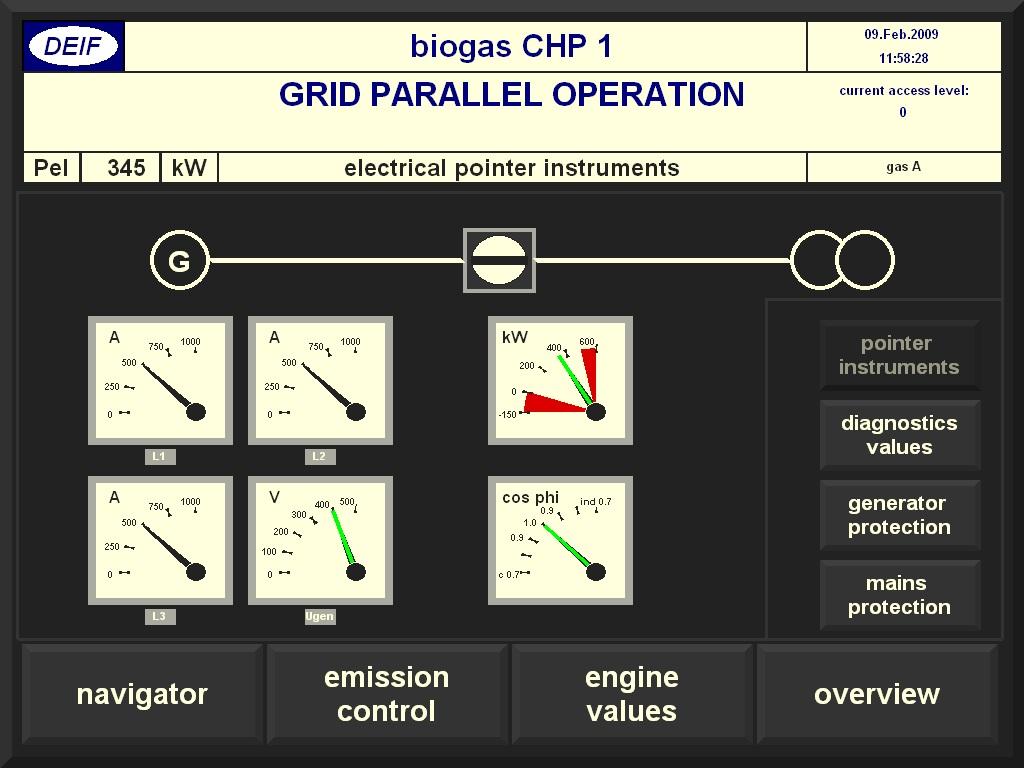
6 1.3 User interface User interface description The DM-4 Gas system shows a unique user interface that allows running the operating terminal function on any standard Windows PC like industrial touch-panel PCs and laptop computers. All possibilities for local and remote access wire-less or wire-bound are available using Ethernet or USB connection to the PCM module. If several users are online at the same time, they see the same user interface, each one on his own computer. The remote start can be blocked by a manual switch on the switchboard panel door for safety reasons. This way - during maintenance - the remote access allows for diagnosis and visualisation, but the start can only be performed locally. The user interface uses a browser principle with universal, plant-independent browser software. The information that has to be displayed is therefore defined on application level. Because of this principle, the data is always consistent. The PCM module is the "Server", whereas the different users are "Clients". Buttons on the fully graphical user surface allow easy access to all visualisation pages. The pages are grouped by themes and can be reached fast and easy either using the menu structure or a central navigator. The status field is structured in the same way on all pages. It shows the state of the plant and - if active - the most important error message. Graphical elements like remote position indicators, bar graphs, pointer instruments for electrical values (kw, A, V, CosPhi) give a full overview of the occurrences that take place at engine, generator, mains and plant. The protections are visualised on special diagnostic pages together with the actual states, measurements, limits and running timers User interface examples DEIF A/S Page 6 of 10

7 DEIF A/S Page 7 of 10
8 Technical information 2. Technical information 2.1 Data, dimensions and disclaimer Technical data Rack system Operating temp.: Vibration class: Protection class: C ( F) DNV A+C 3 mm: Hz, 2.1 g: Hz, 0.7 g: Hz IP 2x Higher class by application of standard housing for DM-4 racks Climate: Class E according to DIN Mounting: EMC/CE: Material: Connectors: Weight: Vertical To EN V2/3/4, SS (PL4) Plastic headers according to UL94-V0, Al housing, steel front plates Phoenix Cage clamp terminals 6/8/20 Arms Screw terminals 20 Arms Depends on configuration PCM 4.3 module Aux. supply: CAN: RS485: 18 30V DC Max. 6 A 3 independent CAN interfaces Mbps Terminals for loop through and termination 1 interface up to Baud, terminals for loop through and termination SCM 4.1 module Safety: To EN Overvoltage category III 690V AC Pollution degree 2 Meas. range (Un): Up to 690 Vrms directly Other ranges after adaptation by VTs../100 or../110v AC Burden max. 0.5 A per phase Overload max. 2*Un tolerated for 10 s External prefuse max. 2 A time-lag DEIF A/S Page 8 of 10
9 Technical information Meas. range (In): Galvanic separation: Frequency: Current transformer../-1 Arms or../-5 Arms Burden max. 0.4 VA per phase Continuous overload 10 Aeff, <75 A - 10 s < 300 A - 1 s 2.5 kv isolation between voltage tips and all other potentials Hz Accuracy: Class 0.5 according to IEC Harmonics: IOM 4.2 Digital inputs: Frequency inputs: Accuracy: Class 1.0 Analogue inputs: Accuracy: Pt100 input: Measurement range: Accuracy: Thermocouple input: Measurement range: Accuracy: Analogue outputs: Accuracy: Digital outputs: Up to 500 Hz are measured 9 36V DC, input resistance type. 2.4 kohm, common reference potential + or -, inputs galvanically separated from other potentials (600 V) Same as digital inputs, but with 2 terminals per input Frequency max. 20 khz pulse-pause ratio > 40% Frequency below 10 khz, pulse-pause ratio >20% 0(4) 20 ma, input impedance type 50 Ohm, galvanically coupled to the analogue outputs, Pt100 inputs and thermocouple inputs, galvanically separated from the rest of the system (600 V rms) 16 bit, better than 0.5% of the full range (40 ma) over the entire temperature range 2-, 3- or 4-wire Pt100 or Pt1000, wire break and short-circuit detection C +/- 0.5 K over the full measurement range with 4-wire connection, +/- 1 K with 3- or 2-wire connection, if cable length less than 1 m 2-wire thermocouple type K (NiCr/Ni) K more than cold junction, temperature compensation by measurement of the cold junction with a single Pt100 sensor in the whole system +/- 5 K (@ C), +/- 10 K (@ C) -20 ma +20 ma, burden up to 500 Ohm 10 bits, better than 0.5% of full range (40 ma) over the entire temperature range Output voltage 8 35V DC with external supply 9 36V DC Output current ma (source and sink) Short-circuit protection by current limitation Short-circuit proof. In case of short-circuit or thermal overload, the outputs will be disabled and an error message will appear DEIF A/S Page 9 of 10
10 Technical information Unit measurements in mm 60 TE rack 42 TE rack PCM PCM TE rack PCM Disclaimer DEIF A/S reserves the right to change any of the contents of this document without prior notice. DEIF A/S Page 10 of 10
Generator Protection Unit, GPU Hydro Multi-line A SW version 2.4X.X
 Multi-line 2 4921240335A SW version 2.4X.X Standard functions Applications Measuring system DEIF A/S Generator protection for hydro turbine driven generators Functions 2 sets of alarm set points Alarm
Delomatic 4, DM-4 Land DATA SHEET
 Delomatic 4, DATA SHEET Application Features Power Management control and protection of complex power systems including diesel, gas and turbine generators, as well as mains and tie breakers Highly flexible
DEIF A/S. Generator Paralleling Controller multi-line L. Type GPC / GS. Compact system in one unit
 Compact system in one unit Generator Paralleling Controller multi-line 2 4921240189L Generator synchronisation, protection and control True 3-phase RMS measurements, voltages and currents galvanically
Delomatic 4, DM-4 Marine & Offshore DATA SHEET
 Delomatic 4, DATA SHEET Application Power management control and protection of complex marine and offshore applications including diesel, gas and turbine generators, as well as tie breakers and shore connections
Basic Gen-set Controller multi-line F SW version 2.31.X or later
 multi-line 2 492124027F SW version 2.1.X or later Standard functions DEIF A/S Applications AMF (no synchronising) Island mode (stand alone) Generator controls Engine start/stop Configurable start sequence
SPARE PART ONLY. Basic Gen-set Controller Multi-line H SW version 2.31.X or later. Data sheet. Standard functions
 Multi-line 2 492124027H SW version 2.1.X or later DEIF A/S Applications AMF (no synchronising) Island mode (stand alone) Generator controls Engine start/stop Configurable start sequence Protection and
PARAMETER LIST DELOMATIC 4, DM-4 GAS CHP CONTROLLER
 PARAMETER LIST DELOMATIC 4, DM-4 GAS CHP CONTROLLER Document no.: 4189340659A SW version 1.33.2 and later Table of contents 1. ABOUT THIS DOCUMENT... 4 GENERAL PURPOSE... 4 INTENDED USERS... 4 CONTENTS/OVERALL
Compact Genset Controller, CGC 400 Generator control and protection Engine monitoring and protection Generator and mains breaker control RS485 Modbus
 DATA SHEET Compact Genset Controller, CGC 400 Generator control and protection Engine monitoring and protection Generator and mains breaker control RS485 Modbus DEIF A/S Frisenborgvej 33 DK-7800 Skive
DATA SHEET Selectable AC transducer, TAS-331DG
 DATA SHEET Selectable AC transducer, TAS-331DG Measures power or reactive power on 3-phase AC networks Class 0.5 (IEC-688) measurement Supply and measuring voltage up to 690 V Easy configuration via PC
DATA SHEET Selectable AC transducer, TAS-321 DG
 DATA SHEET Selectable AC transducer, TAS-321 DG Bi-directional current measurement on AC networks Power measurement using 2 phases on 3-phase networks Class 0.5 (IEC688) measurement Easy configuration
Automatic Gen-set Controller Multi-line D
 Multi-line 2 4921240295D SW version.20.0 or later Standard functions Operation modes Automatic mains failure Island operation Fixed power/base load Peak shaving Load take over Mains power export Push-buttons
DATA SHEET Compact Genset Controller, CGC 200
 DATA SHEET Compact Genset Controller, CGC 200 Auto start and parameter monitoring Warnings and shutdown protections Includes 5 digital inputs, 5 relay outputs Configurable for other applications Licence-free
APU 200 Automatic DATA SHEET Gen-set Controller DATA SHEET
 APU 200 Automatic DATA SHEET Gen-set Controller DATA SHEET Measurement input, auto range Up to 1000 V AC L-L Up to 12.5 A (sinusoidal) 16 400 Hz Output Up to four analogue outputs Relay output RS 485 Modbus
Engine Controller EC-1
 Engine Controller 4921240292E Standard functions Engine control Engine monitoring DEIF A/S Start preparation (preheater or prelubrication) Start/stop sequences with selectable no. of start attempts Fuel
Generator Controller GC-1
 4921240293F Standard functions DEIF A/S Engine control Start preparation (preheater or prelubrication) Start/stop sequences with selectable no. of start attempts Fuel solenoid selection (coil type) Idle
No longer for sale. Generator Controller GC-1. Data sheet. Standard functions
 4921240293F DEIF A/S Engine control Start preparation (preheater or prelubrication) Start/stop sequences with selectable no. of start attempts Fuel solenoid selection (coil type) Idle speed control Local
Generator Protection Unit, GPU-3 Gas Generator protection (ANSI) Busbar protection (ANSI) M-Logic (Micro PLC) Display General
 Busbar protection (ANSI) M-Logic (Micro PLC) Display General") DATA SHEET Generator Protection Unit, GPU-3 Gas Generator protection (ANSI) Busbar protection (ANSI) M-Logic (Micro PLC) Display General DEIF A/S Frisenborgvej 33 DK-7800 Skive Tel.: +45 9614 9614 Fax:
DATA SHEET Generator Protection Unit, GPU-3 Gas Generator protection (ANSI) Busbar protection (ANSI) M-Logic (Micro PLC) Display General DEIF A/S Frisenborgvej 33 DK-7800 Skive Tel.: +45 9614 9614 Fax:
Generator Protection Unit, GPU-3 DATA SHEET
 DATA SHEET Generator Protection (ANSI) 2 x reverse power (32) 5 x overload (32) 6 x overcurrent (50/51) 2 x overvoltage (59) 3 x undervoltage (27) 3 x over-/underfrequency (81) Voltage dependent overcurrent
Installation Manual. Multi Power Controller MPC-1 multi-line D
 Installation Manual Multi Power Controller MPC-1 multi-line Complete control system in one package: - island operation - parallel with mains operation - emergency generator control 3-phase AC measurements
MIC-2 Multi-instrument DATA SHEET
 Measurements All 3-phase AC measurements True RMS 4-Quadrant energy Power Quality Analysis Replaces analogue meters RS-485 Modbus RTU protocol TCP/IP Modbus (optional) Profibus DP (optional) I/O modules
Engines & Gen-sets N, page 1 of 6
 Uni-line ANSI code 27, 59 ANSI code 59 ANSI code 27 RMV-112D RMV-122D RMV-12D Under- /overvoltage protection: Overvoltage protection (2 levels Undervoltage protection (2 levels 1 minimum and 1 maximum
AGC 200 Advanced Gen-set Controller DATA SHEET
 AGC 200 Advanced Gen-set Controller DATA SHEET Operation modes Automatic mains failure Island operation Fixed power/base load Peak shaving Load take over Mains power export Protection (ANSI) 5 x Overload
Engine Control Unit, ECU 100 Engine control Engine monitoring and protection Easy-to-read graphical display Integrated emulation software solution
 DATA SHEET Engine Control Unit, ECU 100 Engine control Engine monitoring and protection Easy-to-read graphical display Integrated emulation software solution DEIF A/S Frisenborgvej 33 DK-7800 Skive Tel.:
AGC 200 Automatic Advanced Gen-set Controller DATA SHEET
 200 Automatic DATA SHEET Operation modes Automatic mains failure/ats Island operation Fixed power/base load Peak shaving Load takeover Mains power export Multiple gen-set load sharing (128) Display and
Basic Gen-set Controller G (UK) SW version 2.1X.X. Terminal strip overview
 SW version 2.1X.X. Terminal strip overview") Basic Gen-set Controller 4189340302G (UK) SW version 2.1X.X Mounting Board slot positions Terminal strip overview DEIF A/S I/O lists Wiring DEIF A/S, Frisenborgvej 33 Tel.: +45 9614 9614, Fax: +45 9614
Basic Gen-set Controller 4189340302G (UK) SW version 2.1X.X Mounting Board slot positions Terminal strip overview DEIF A/S I/O lists Wiring DEIF A/S, Frisenborgvej 33 Tel.: +45 9614 9614, Fax: +45 9614
DATA SHEET Applicable for offshore or nearshore
 AWC 400 Advanced Wind Turbine Controller DATA SHEET Applicable for offshore or nearshore environments Unrivalled robustness 5-year warranty Open programming in ANSI C/C and IEC63-3 DEIF A/S Frisenborgvej
MIC-2 MKII & MIC-2 MKII DIN, Multi-instrument DATA SHEET
 & DIN, Multi-instrument DATA SHEET Measurements All 3-phase AC measurements True RMS 4-Quadrant energy Power Quality Analysis Replaces analogue meters RS-485 Modbus RTU protocol TCP/IP Modbus (optional)
DATA SHEET IOM 200 analogue interface for AGC 200
 DATA SHEET IOM 200 analogue interface for AGC 200 CAN interface to AGC 200 series TTL interface to PC LED indicators for unit and CANbus status GOV/AVR outputs selectable for DC current or DC voltage DEIF
Advanced Genset Controller, AGC 200 Operation modes Display and unit front General Engine control M-Logic Optional applications
 DATA SHEET Advanced enset Controller, 200 Operation modes Display and unit front eneral Engine control M-Logic Optional applications DEIF A/S Frisenborgvej 33 DK-7800 Skive Tel.: +45 9614 9614 Fax: +45
MULTI-LINE 2 APPLICATION NOTES. Converting PPU-2 to PPU-3 Parameter conversion Wiring Options I/O list. Document no.: A SW version:
 MULTI-LINE 2 APPLICATION NOTES Converting PPU-2 to PPU-3 Parameter conversion Wiring Options I/O list DEIF A/S Frisenborgvej 33 DK-7800 Skive Tel.: +45 9614 9614 Fax: +45 9614 9615 info@deif.com www.deif.com
Generator Protection Unit, GPU-3 DATA SHEET
 DATA SHEET Generator protection (ANSI) 2 x reverse power (32) 5 x overload (32) 6 x overcurrent (50/51) Inverse time overcurrent (51) 2 x overvoltage (59) 3 x undervoltage (27) 3 x over-/underfrequency
DATA SHEET. AGC PM Automatic Genset Controller, Plant Management
 DATA SHEET AGC PM Automatic Genset Controller, Plant Management Management of up to 992 gensets Island and parallel operation Plant black start capabilities Fuel-optimised control Integrated genset protection
Generator Controller GC-1F
 Controller 4921240310D Standard functions DEIF A/S Engine control Start preparation (preheating or prelubrication) Start/stop sequences with selectable no. of start attempts Fuel solenoid selection (coil
Generator Paralleling Controller, GPC-3 DATA SHEET
 DATA SHEET Regulation modes Load sharing Fixed frequency Fixed power Frequency droop Generator protection (ANSI) 2 x reverse power (32) 5 x overload (32) 6 x overcurrent (50/51) 2 x overvoltage (59) 3
Comprehensive Modular Genset Controller
 Inteligen Learn More Comprehensive Modular Genset Controller Brief Description The Inteligen is a comprehensive controller for single and multiple generating sets operating in standby or parallel to the
Advanced Genset Controller, AGC 200 Operation modes Display and unit front General Engine control M-Logic Optional applications
 DATA SHEET Advanced enset Controller, 200 Operation modes Display and unit front eneral Engine control M-Logic Optional applications DEIF A/S Frisenborgvej 33 DK-7800 Skive Tel.: +45 9614 9614 Fax: +45
MULTI-LINE 2 APPLICATION NOTES
 MULTI-LINE 2 APPLICATION NOTES Converting PPM-2 to PPM 300 Parameter conversion Wiring Options I/O list Modbus DEIF A/S Frisenborgvej 33 DK-7800 Skive Tel.: +45 9614 9614 Fax: +45 9614 9615 info@deif.com
DATA SHEET DEPRECATED - PCM5 1. Document no.: N/A
 DATA SHEET DEPRECATED - PCM DEIF A/S Frisenborgvej DK-800 Skive Tel.: +4 64 64 Fax: +4 64 6 info@deif.com www.deif.com Document no.: N/A AWC 00 PCM data sheet - DEPRECATED. AWC 00 system. System specifications...
PPM Protection and Power Management DATA SHEET
 PPM DATA SHEET Power Management Multiple master system Redundant internal communication Load-dependent start/stop Fuel optimisation logic Programmable start priority Heavy consumer control Blackout start
DEIF A/S. TAS-331DG Selectable AC transducer G (UK) Installation and start up instructions. Watt or var transducer
 Installation and start up instructions. Watt or var transducer") Installation and start up instructions TAS-331DG Selectable AC transducer 4189300008G (UK) Watt or var transducer Supply and measuring voltage up to 690V DEIF A/S Configuration via PC-interface possible
Installation and start up instructions TAS-331DG Selectable AC transducer 4189300008G (UK) Watt or var transducer Supply and measuring voltage up to 690V DEIF A/S Configuration via PC-interface possible
Genset control and protection with safety system
 APPLICATION NOTES Generator Protection Unit, GPU-3 APPLICATION NOTES Genset control and protection with safety system Application description Functional description Wiring I/O lists Basic setup Flowcharts
DEIF A/S. MIC Multi-instrument G. Data sheet. Features. Accuracy. Measurements. Installation. Intelligent. Display. Communication DEIF A/S
 Multi-instrument 4921210107G Features Measurements All 3-phase AC measurements True RMS Replaces analogue meters Intelligent Suitable for all 3-phase network topologies Replaces transducers Accuracy U,
DATA SHEET Genset Controller, GC-1F
 DATA SHEET Genset Controller, Engine control Generator monitoring Generator protection (ANSI) Mains monitoring Mains protection (ANSI) Engine monitoring Display panel DEIF A/S Frisenborgvej 33 DK-7800
Generator Paralleling Controller, GPC-3 Gas Regulation modes Generator protection (ANSI) M-Logic (Micro PLC) Busbar protection (ANSI) Display General
 M-Logic (Micro PLC) Busbar protection (ANSI) Display General") DATA SHEET Generator Paralleling Controller, GPC-3 Gas Regulation modes Generator protection (ANSI) M-Logic (Micro PLC) Busbar protection (ANSI) Display General DEIF A/S Frisenborgvej 33 DK-7800 Skive
DATA SHEET Generator Paralleling Controller, GPC-3 Gas Regulation modes Generator protection (ANSI) M-Logic (Micro PLC) Busbar protection (ANSI) Display General DEIF A/S Frisenborgvej 33 DK-7800 Skive
Multi-instrument Communication, MIC-2 MKII DIN Quick Start Guide
 Multi-instrument Communication, MIC-2 MKII DIN Quick Start Guide Warnings and legal information Installation and terminals Communication I/O options Alarming Utility software More information Specifications
General introduction Part 2, chapter 11
 Delomatic 4 DM-4 Land/DM-4 Marine General introduction Part 2, chapter 11 DEIF A/S Page 1 of 8 Document no.: 4189232111C Table of contents 11. THE DELOMATIC SYSTEM IN GENERAL... 3 GENERAL INTRODUCTION...
Generator Protection Unit, GPU-3 Generator protection (ANSI) Busbar protection (ANSI) M-Logic (Micro PLC) Display General
 Busbar protection (ANSI) M-Logic (Micro PLC) Display General") DATA SHEET Generator Protection Unit, GPU-3 Generator protection (ANSI) Busbar protection (ANSI) M-Logic (Micro PLC) Display General DEIF A/S Frisenborgvej 33 DK-7800 Skive Tel.: +45 9614 9614 Fax: +45
DATA SHEET Generator Protection Unit, GPU-3 Generator protection (ANSI) Busbar protection (ANSI) M-Logic (Micro PLC) Display General DEIF A/S Frisenborgvej 33 DK-7800 Skive Tel.: +45 9614 9614 Fax: +45
DATA SHEET. Advanced Energy Meter, AEM 380 & AEM 305
 DATA SHEET Advanced Energy Meter, AEM 380 & AEM 305 Easy installation MID-approved 5 optional communication interfaces Phase error detection Low power consumption Two tariffs Two-pulse output DEIF A/S
Multi-instrument Communication, MIC-2 MKII DIN Quick Start Guide
 Multi-instrument Communication, MIC-2 MKII DIN Quick Start Guide Warnings and legal information Installation and terminals Communication I/O options Alarming Utility software More information Specifications
Multiple Generator Automatic Synchronising System
 R Millennium Power Manufacturing Corp. R Multiple Generator Automatic Synchronising System Synchronising System Type Choice Independent Control Cabinet Type Feature: Independent Control Cabinet Type Functions:
North Power 5H04 PRIME POWER:454 KVA KW STANDBY POWER: 504 KVA KW
 DATA SHEET North Power 5H04 STANDBY POWER: 504 KVA - 403 KW Standard Specifications Water cooled, Diesel engine Radiator with mechanical fan Protective grille for rotating and hot parts Electric starter
DELOMATIC - MULTI-FUNCTION SYSTEM PART 2 INSTALLATION INSTRUCTION
 CONTENTS: 25.0...2 25.1 SYSTEM INSTALLATION...2 25.1.1 Before installing the DELOMATIC system...2 25.1.2 Installing the DGU...3 25.1.3 Installing the CP...4 25.1.4 Connecting the power supply...6 25.1.5
Multifunction Transducer MT440
 Multifunction Transducer MT440 Voltage and current auto range measurements up to 600V, 12.5A Universal wide auxiliary power supply range 24 300 Vdc, 40 276 Vac Power accuracy class 0.5 (EN 60 688), Up
Option H3 Serial communication Profibus DP
 MULTI-LINE 2 DESCRIPTION OF OPTIONS Option H3 Serial communication Profibus DP Description of option Functional description Parameters Data tables Document no.: 4189340443H Multi-line 2 Option H3, Serial
DEIF A/S. Description of options. Option C1 Generator add-on protection package Multi-line 2 version 2. Description of options. Functional description
 Description of options Option C1 Generator add-on protection package Multi-line 2 version 2 4189340267E SW version 2.42.X Description of options DEIF A/S Functional description Parameter list DEIF A/S,
ATV1200A kv kva
 Characteristics medium voltage variable speed drive ATV1200-10 kv - 5000 kva Main Range of product Altivar 1200 Product or component type Device short name Product destination Product specific application
ATV1200A kv kva
 Characteristics medium voltage variable speed drive ATV1200-3.3 kv - 3500 kva Main Range of product Altivar 1200 Product or component type Device short name Product destination Product specific application
ATV1200A kv kva. Phase-shifting transformer Medium voltage arrestors Cooling fans Human machine interface Plinth (2) Power cells (9)
 Power cells (9)") Characteristics medium voltage variable speed drive ATV1200-3.3 kv - 370 kva Main Range of product Altivar 1200 Product or component type Device short name Product destination Product specific application
Characteristics medium voltage variable speed drive ATV1200-3.3 kv - 370 kva Main Range of product Altivar 1200 Product or component type Device short name Product destination Product specific application
DATA SHEET Automatic Genset Controller, AGC-3
 DATA SHEET Automatic enset, AC-3 Operation modes Engine control enerator protection (ANSI) Display /busbar protection (ANSI) M-Logic (Micro PLC) eneral DEIF A/S Frisenborgvej 33 DK-7800 Skive Tel.: +45
Faults on the system Proximity switch connection technology:
 Speed monitor for connection to a base unit from the PNOZmulti modular safety system Approvals Unit features Monitoring of 2 independent axes Connection of 2 incremental encoders or 4 proximity switches
Option M2 Configurable engine control cards Multi-line 2 version B SW version 2.4X.X
 Description of options Option M2 Configurable engine control cards Multi-line 2 version 2 4189340482B SW version 2.4X.X Description of options Functional description DEIF A/S Display units Additional functions
MIC-2 MKII, Multi-instrument DATA SHEET
 MIC-2 MKII, Multi-instrument DATA SHEET Measurements All 3-phase AC measurements True RMS 4-Quadrant energy Power Quality Analysis Replaces analogue meters RS-485 Modbus RTU protocol TCP/IP Modbus (optional)
DATA SHEET. Advanced Power Meter, APM 380 & APM 305
 DATA SHEET Advanced Power Meter, APM 380 & APM 305 Easy installation Monitors all 3 phases 5 optional communication interfaces Phase error detection Low power consumption Two-pulse output DEIF A/S Frisenborgvej
MID approval no. DE-08-MI004-PTB004 Date of release
 1. Identification Energy and Flow Computer Flow rate and energy calculator for liquids, gases and water steam E-DB-1000-700-01 MID approval no. DE-08-MI004-PTB004 Date of release 04.01.08 2. Area of Application
QUICK START GUIDE Paralleling and Protection Unit PPU 300
 QUICK START GUIDE Paralleling and Protection Unit PPU 300 DEIF A/S Frisenborgvej 33 DK-7800 Skive Tel.: +45 9614 9614 Fax: +45 9614 9615 info@deif.com www.deif.com Document no.: 4189341107B 1. Introduction
DATA SHEET Paralleling and Protection Unit, PPU-3
 DATA SHEET Paralleling and Protection Unit, PPU-3 Regulation modes Generator protection M-Logic (Micro PLC) Busbar protection Free PC utility software Approved by all major classification societies DEIF
Safety Temperature Limiter TT-STL 50
 GmbH Postal address: House address Fon (+49) 0 22 42-8703-0 Postbox 1261 Löhestr. 37 Fax (+49) 0 22 42-8703-20 http: // www.tematec.de 53759 Hennef 53773 Hennef e-mail: team@tematec.de Safety Temperature
Panorama rudder indicator TRI-2 Analogue or CAN input Approved according to MED Three extra large scales Long-life LED illumination Built-in dimmer
 USER'S MANUAL Panorama rudder indicator TRI-2 Analogue or CAN input Approved according to MED Three extra large scales Long-life LED illumination Built-in dimmer DEIF A/S Frisenborgvej 33 DK-7800 Skive
QUICK START GUIDE Paralleling and Protection Unit PPU 300
 QUICK START GUIDE Paralleling and Protection Unit PPU 300 DEIF A/S Frisenborgvej 33 DK-7800 Skive Tel.: +45 9614 9614 Fax: +45 9614 9615 info@deif.com www.deif.com Document no.: 4189341107C 1. Introduction
PPU Power Management (PPM)
") PPU anagement (PP) 4921240291H Standard functions DEIF A/S management Load dependent start/stop Programmable start priority Heavy consumer control Blackout start sequence Supervision/control of a shore
PPU anagement (PP) 4921240291H Standard functions DEIF A/S management Load dependent start/stop Programmable start priority Heavy consumer control Blackout start sequence Supervision/control of a shore
Compact Genset Controller, CGC 400 What's in the delivery? The first steps Push-buttons and LEDs
 QUICK START GUIDE Compact Genset Controller, CGC 400 What's in the delivery? The first steps Push-buttons and LEDs DEIF A/S Frisenborgvej 33 DK-7800 Skive Tel.: +45 9614 9614 Fax: +45 9614 9615 info@deif.com
DATA SHEET LAN Server For Energy and Power meters AEM and APM with Modbus interface
 DATA SHEET For Energy and Power meters AEM and APM with Modbus interface Data logging Web Server interface Gateway - Modbus TCP/IP FTP DynDNS Up to 32 Energy and Power meters DEIF A/S Page 1 of 9 Document
Compact universal controllers
 7 867 Compact universal controllers RWF55... The RWF55 is used mainly for controlling the temperature or pressure in oil- or gas-fired heating plants. If the relevant parameters are set, the RWF55 can
DGSZV-EP DIGITAL GALVANIC LONGITUDINAL DIFFERENTIAL PROTECTION. Application field
 DGSZV-EP DIGITAL GALVANIC LONGITUDINAL DIFFERENTIAL PROTECTION The digital galvanic longitudinal differential protection of type DGSZV-EP is part of device family named EuroProt. This short description
with Backlight Graphic LCD Screen
 with Backlight Graphic LCD Screen ENERGY AND AUTOMATION POWER OF ENERGY SAVING For the control of energy distribution systems detecting when problems occur that could put the quality and availability of
Generator Paralleling Controller, GPC-3 Regulation modes Generator protection (ANSI) M-Logic (Micro PLC) Busbar protection (ANSI) Display General
 M-Logic (Micro PLC) Busbar protection (ANSI) Display General") DATA SHEET Generator Paralleling Controller, GPC-3 Regulation modes Generator protection (ANSI) M-Logic (Micro PLC) Busbar protection (ANSI) Display General DEIF A/S Frisenborgvej 33 DK-7800 Skive Tel.:
DATA SHEET Generator Paralleling Controller, GPC-3 Regulation modes Generator protection (ANSI) M-Logic (Micro PLC) Busbar protection (ANSI) Display General DEIF A/S Frisenborgvej 33 DK-7800 Skive Tel.:
GC2000 Generator Controller Power Management and Protection
 GC2000 Generator Controller Power Management and Protection Control. Monitor. Protect. A powerful generator controller and power management system for marine and offshore applications SELCO s GC2000 provides
Voltage Transducer UMT516 / MT516
 Voltage Transducer UMT516 / MT516 True RMS AC voltage measurements Voltage auto range measurements up to 600V # Wide frequency measurement range 16 400 Hz High accuracy class 0.2 (IEC-688), 0.1 on communication
QUICK START GUIDE Generator Protection Unit GPU 300
 QUICK START GUIDE Generator Protection Unit GPU 300 DEIF A/S Frisenborgvej 33 DK-7800 Skive Tel.: +45 9614 9614 Fax: +45 9614 9615 Info@deif.com www.deif.com Document no.: 4189341035A 1. Introduction 1.1
Controller module. Brief description. Features. Block structure. Page 1/7. Data Sheet
 JUMO GmbH & Co. KG Delivery address:mackenrodtstraße 14, 36039 Fulda, Germany Postal address: 36035 Fulda, Germany Phone: +49 661 6003-0 Fax: +49 661 6003-607 E-mail: mail@jumo.net Internet: www.jumo.net
PowerLogic power-monitoring units. Power Meter PM500. Technical data sheet 2006
 PowerLogic power-monitoring units Technical data sheet 2006 Functions and characteristics E90463 The PowerLogic PM500 Power Meter provides all measurement capabilities required to monitor an electrical
Compact Universal Controllers
 7 865 ISO9001 RWF40... complete with housing Compact Universal Controllers RWF40... The RWF40... is a universal digital boiler temperature / pressure controller with functions designed specifically for
QUICK START GUIDE Generator Paralleling Controller, GPC-3 Generator Protection Unit, GPU-3/GPU-3 Hydro Paralleling and Protection Unit, PPU-3
 QUICK START GUIDE Generator Paralleling Controller, GPC-3 Generator Protection Unit, GPU-3/GPU-3 Hydro Paralleling and Protection Unit, PPU-3 What's in the delivery? Getting started The first steps PC
UNITROL 1000 Compact Automatic Voltage Regulator for small synchronous machines UNITROL
 UNITROL 1000 Compact Automatic Voltage Regulator for small synchronous machines UNITROL 1000-7 Copyright 2000 Photodisc, Inc. 5973-04 Applications of UNITROL 1000-7 UNITROL 1000-7 is the latest and most
Switching and controlling in the switch cabinet
 Switching and controlling in the switch cabinet Relays Opto-coupler Solid state relays Intelligent interface technology 02 03 MIRO INTERFACE TECHNOLOGY MINIMUM SPACE MAXIMUM FUNCTIONALITY Application areas
Digital Overspeed Protection System with PROFIBUS -DP interface DOPS, DOPS AS, DOPS TS
 Digital Overspeed Protection System with PROFIBUS -DP interface DOPS, DOPS AS, DOPS TS Application: The speed measurement and overspeed protection systems DOPS and DOPS AS serve the measurement of speeds
Artisan Technology Group is your source for quality new and certified-used/pre-owned equipment
 Artisan Technology Group is your source for quality new and certified-used/pre-owned equipment FAST SHIPPING AND DELIVERY TENS OF THOUSANDS OF IN-STOCK ITEMS EQUIPMENT DEMOS HUNDREDS OF MANUFACTURERS SUPPORTED
DEIF A/S. Description of options. Option A and B, Loss of mains protection package Automatic Gen-set controller. Description of options
 Description of options Option A and B, Loss of mains protection package Automatic Gen-set controller 4189340394B SW 2.3X.X Description of options Functional descriptions DEIF A/S Parameter list DEIF A/S,
TSXCTY2A 2 channels counter modules - 40 khz - 30 ma at 24 V DC, 280 ma at 5 V DC
 Characteristics 2 channels counter modules - 40 khz - 30 ma at 24 V DC, 280 ma at 5 V DC Main Range of product Product or component type I/O modularity Mar 05, 2018 Modicon Premium Automation platform
DIGITAL RELAY OF PROTECTION AND AUTOMATION SERIES PC83 AND PC830
 DIGITAL RELAY OF PROTECTION AND AUTOMATION SERIES PC83 AND PC830 PC83 and PC830 series devices are designed to perform the relay protection functions and 6-154 kv networks automation, have different functionality
CSI 6300 SIS Overview
 Overview The Digital Overspeed Protection System is TÜV - certified according to IEC 61508:2010 and provides speed measurement and detection of rotational direction for rotating machines such as turbines,
Controller module. Brief description. Features. Block structure. Data Sheet Page 1/7
 M. K. Juchheim GmbH & Co UK USA Jumo Instrument Co. Ltd. Jumo Process Control Inc. 36035 Fulda, Germany Temple Bank, Riverway 735 Fox Chase Phone (0661) 6003-0 Harlow, Essex CM20 2TT Coatesville, PA 19320
DINALOG A 144 x 36 A1400 Light-Strip Indicator
 DINALOG A x 6 A00 Light-Strip Indicator -9-0-0 /.00 Front panel dimensions: x 6 mm Light-strip indicator with 7 high-contrast LEDs Red LED display color Digital display range for portrait format: 999 to
DATA SHEET Advanced Wind turbine Controller, AWC 500
 DATA SHEET Advanced Wind turbine Controller, AWC 500 DEIF A/S Frisenborgvej 33 DK-7800 Skive Tel.: +45 9614 9614 Fax: +45 9614 9615 info@deif.com www.deif.com Document no.: 4921240395G 1. AWC 500 system
JUMO Quantum PID100/PID200/PID300
 Data sheet 702020 Page 1/12 JUMO Quantum PID100/PID200/PID300 Universal PID Controller Series Brief description The Quantum series is available in the three DIN formats 48 mm x 48 mm, 48 mm x 96 mm, and
TYPE APPROVAL CERTIFICATE
 TYPE APPROVAL CERTIFICATE Certificate No: TAA00000KD Revision No: 1 This is to certify: That the Electrical Measuring and Protection Relay with type designation(s) PPU-3, GPU-3 - Generator Controllers
PM174 PM174 IEEE1159 ADVANCED POWER QUALITY ANALYZER. Features
 PM174 IEEE1159 ADVANCED POWER QUALITY ANALYZER The PM174 is a compact, multi-function, three-phase AC powermeter and power quality analyzer specially designed to meet the requirements of users ranging
4100 and 4100/R Controllers
 The TR TASC Unit speed controller is available in two formats: 4100 for panel mounting 4100/R for rack mounting Facilities are identical for the two models. Construction The p.c.b. card is 0.0625 in flame
T500 DUALTACH. JAQUET T500 DualTach. 2 channel measurement & monitoring instrument 2 CHANNEL TACHOMETER I N C H A R G E O F S P E E D.
 1-08 T500 DUALTACH 2 CHANNEL TACHOMETER JAQUET T500 DualTach 2 channel measurement & monitoring instrument JAQUET T500 DualTach 2 channel measurement and monitoring instrument for demanding machine protection