CONTENTS. dspicpro4 KEY FEATURES 4 CONNECTING THE SYSTEM 5 INTRODUCTION 6
|
|
|
- Francine Walsh
- 5 years ago
- Views:
Transcription
1
2
3 CONTENTS dspicpro4 KEY FEATURES 4 CONNECTING THE SYSTEM 5 INTRODUCTION 6 Switches and Jumpers 7 MCU Sockets 8 Power Supply 10 On-Board USB 2.0 Programmer 11 MikroICD 12 RS-232 Communication Circuit 13 Ethernet 14 DS1820 Digital Thermometer 16 DAC 17 Real Time Clock (RTC) 18 RS-485 Communication 19 CAN Circuit 20 LEDs 21 Push Buttons 22 2x16 Character LCD 23 Graphic LCD 24 Touch Panel 25 A/D Converter Test Input 26 Direct Port Access Connectors 27 MMC/SD (Multimedia Card) 28

4 4 DSPICPRO4 KEY FEATURES 1. External power supply 9-32V AC/DC; 2. On-Board USB 2.0 Programmer with MikroICD support; 3. RS232-A connector; 4. RS232-B connector; 5. Reference voltage source 4.096V; 6. On-board serial ethernet module; 7. LCD 2x16 connector; 8. LCD contrast potentiometer; 9. A/D converter test inputs; 10. DS1820 temperature sensor connector; 11. Resistor pull-up/pull-down net 8x10K; 12. Real time clock; 13. DAC module; 14. RS485 module; 15. CAN module; 16. Each LED corresponds to one MCU pin; 17. DIP switch SW1used to enable/disable LEDs; 18. dspicpro4 supports 64 and 80-pin microcontrollers and comes with 80-pin microcontroller dspic30f6014a; 19. DIP switches SW2-SW5 are used to enable/disable on-board peripherals; 20. Direct ports access connectors; 21. MMC/SD multimedia card slot; 22. RESET button circuit; 23. Push buttons; 24. Touch panel connector; 25. GLCD connector; 26. GLCD contrast potentiometer; 27. Touch panel controller; and 28. Pull-up/pull-down jumper.
5 CONNECTING THE SYSTEM 5 Apart from this manual, the development system box contains development system, product CD, USB cable, RS232 cable and Installing USB drivers manual. In order to use the dspicpro4 properly, it is necessary to go through the following steps: Step no.1 Step no.2 Step no.3 Step no.4 Take the development system and product CD out of the box. Insert the product CD into CD drive. Please, do not connect the development system to a PC yet. Install dspic flash programmer software to enable a program to be transferred from PC to the microcontroller chip. Install USB drivers on your PC to enable programmer's hardware to operate properly on the dspicpro4 board. For detailed installation instructions refer to the 'Installing USB drivers' manual. Connect the dspicpro4 to PC using USB cable. Please use one of USB ports on the back of the PC because they are directly connected to the computer motherboard. The first time you switch the dspicpro4 on, your PC will automatically detect a new hardware. You will be immediately prompted whether Windows should search for new drivers update or not. Select the option 'No, not this time' and click 'Next'. Another window appears, click 'Next' and the operating system will automatically find drivers. Click 'Finish' to complete this process and run dspicflash. Next time you switch the dspicpro4 on, Windows will not ask for new drivers update during driver installation.. CONNECTING THE SYSTEM After these four steps, your dspicpro4 is successfully installed and ready for use. You can read a program from the chip or write a new one into it. The product CD provides numerous simple program examples to make your first steps Easy....
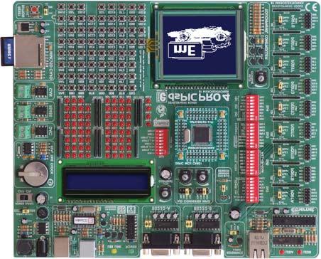
6 6 INTRODUCTION INTRODUCTION The dspicpro4 development system is a full-featured development board for dspic Microchip microcontrollers. It is designed to allow students and engineers to easily test and explore the capabilities of dspic microcontrollers. It also allows dspic microcontrollers to be interfaced with external circuits and a broad range of peripheral devices. The user can therefore concentrate on software development only. Figure 1 illustrates the development board. There are identification marks next to each component on a silkscreen, both on the top and bottom. These marks describe connections to the microcontroller, operation modes, and provide other useful information so that there is almost no need for additional schematics. Figure 1 dspicpro4 development board

7 SWITCHES 7 The dspicpro4 development system features a number of peripheral devices. In order to enable them before programming, the appropriate jumpers or switches have to be properly set. Switches are mechanical devices used to establish or break connection between two contacts. The dspicpro4 development system has five groups of switches. Figure 2 Switch group SW5 Switches 1, 2, 3 and 4 are ON, whereas 5, 6, 7 and 8 are OFF DIP switch SW1 enables/disables LEDs; DIP switch SW2 enables/disables LCD,GLCD-BCK, CAN, RS-485 and RTC-INT; DIP switch SW3 enables/disables touch panel controller and ethernet; DIP switch SW4 enables/disables MMC-CS, DAC, SPI and I 2 C; and DIP switch SW5 enables/disables PORTB_HIGH pull-up/pull-down resistors. JUMPERS SWITCHES AND JUMPERS Similarly, jumpers are used to break or establish connection between two points. Under the plastic cover of a jumper, there is a metal contact which establishes connection when the jumper is placed over two pins. Jumper is commonly used as a selector between two possible connections via 3-pin connector. As illustrated in Figure 3, the middle connector pin can be connected to the left or right pin, depending on the jumper s position. Jumper is not placed and middle pin is unconnected. Jumper is placed on the right side connecting middle and right pin. Jumper is placed on the left side connecting middle and left pin. Figure 3 Jumper as a selector


8 8 MCU SOCKET MCU SOCKET The dspicpro4 comes with an 80-pin dspic30f6014a microcontroller in TQFP soldered on MCU card. The user can remove this MCU card and fit another one with either 64 or 80-pin microcontroller on it. Figure 4 MCU card When placing MCU card in the dspicpro4 MCU socket, it is necessary to follow the steps below: Step no. 1 If MCU card is already placed on the dspicpro4, it is necessary to remove it by slowly pulling it up. Step no. 2 Place another MCU card on the board. Note that label on the MCU card must be in the upper left corner as labelled on the dspicpro4 board. Step no. 3 When the MCU card is properly placed, push it down by applying pressure on all edges at the same time.


9 The microcontroller pins are routed to various peripherals as illustrated in Figure 5. All ports have direct connections to Direct Port Access 2x5 (10-pin) connectors. These connectors are typically used for connecting external peripherals to the board or as points for digital logic probe connecting. 9 All port pins are connected to LEDs and push buttons, which allows you to easily monitor and test digital pin state. Some of the pins are connected to other peripherals such as DS1820 temperature sensor circuit, RS-232 communication circuit, RS-485 communication circuit, LCD etc. MCU SOCKET Figure 5 MCU system connection
.")


10 10 POWER SUPPLY POWER SUPPLY The dspicpro4 can use one out of two power supply sources - regulated PC supply over USB cable (by default) and external power supply (external AC/DC power adapter). When using power supply over USB cable, the jumper J10 should be set in the right-hand position. When using external power supply, the dspicpro4 board produces +5V using MC34063A voltage regulator. The external power supply can be AC or DC, while power supply voltage ranges from 9V to 32V. The jumper J10 should be set in the left-hand position. Figure 7 illustrates USB and external power supply circuits. Figure 6 Power supply Figure 7 Power supply circuit diagram J1 in the left-hand position: system is powered from external AC/DC power adapter. J1 in the right-hand position: system is powered from PC over USB cable.

11 ON-BOARD USB 2.0 PROGRAMMER 11 There is no need to use external equipment during programming as the dspicpro4 development system has its own on-board USB 2.0 programmer. All you need to do is to connect the system to PC using the USB cable. Then, load your program into the microcontroller via the dspicflash programming software supplied with the dspicpro4. Please refer to dspicflash documentation for more information. Figure 8 USB 2.0 programmer ON-BOARD USB 2.0 PROGRAMMER Figure 9 USB 2.0 programmer circuit diagram Note: There is no need to reset MCU after programming because the programmer will automatically reset it.
12 12 MIKROICD (HARDWARE IN-CIRCUIT DEBUGGER) MIKROICD (HARDWARE IN-CIRCUIT DEBUGGER) MikroICD is a highly effective tool for Real-Time debugging on hardware level. The mikroicd debugger enables you to execute a program on dspic microcontroller and view variable values, special function registers (SFRs) and EEPROM while the program is running. MikroICD can be used with any dspic compiler designed by MikroElektronika (mikroc for dspic, mikrobasic for dspic or mikropascal for dspic). You just have to select the appropriate build type (Release or ICD Debug), build a project, program the MCU and run debugger. The mikroicd debugger uses on-board programmer to communicate with the compiler and supports common debugger commands: Start Debugger Run/ Pause Debugger Toggle Breakpoints Run to cursor Step Into Step Over Flush RAM Stop Debugger Note: [F9] [F6] [F5] [F4] [F7] [F8] [F2] [Ctrl+F2] Figure 10 MikroICD circuit diagram For more information on how to use mikroicd debugger please refer to the mikroicd documentation mikroicd User s Manual. You can also find it in Help documentation inside any compiler mentioned.

13 RS-232 COMMUNICATION 13 RS-232 communication enables point-to-point data transfer. It is commonly used in data acquisition applications to transfer data between the microcontroller and PC. Since the voltage levels of the microcontroller and PC are not directly compatible with each other, a level converter such as MAX232, must be used. In order to provide more flexible system, the microcontroller is connected to MAX232 via jumpers J12 and J13 for RS-232A and jumpers J14 and J15 for RS-232B. The jumpers J12 and J13 are therefore used to connect Rx and Tx lines to RF2 and RF3 pins, whereas the jumpers J14 and J15 are used to connect Rx and Tx lines to RF4 and RF5 pins. Figure 11 RS-232 communication Figure 12 RS-232 communication circuit diagram

14 14 ETHERNET ETHERNET Ethernet is most commonly used Local Area Network (LAN) technology today. On the top of physical layer, Ethernet stations mutually communicate by sending data packets to each other. Each station is assigned a single 48-bit MAC address which is used to specify both destination and source of each data packet. Ethernet has 28-pin ENC28J60 10BASE-T Ethernet Controller with on-board Media Access Control and Physical Layer (MAC & PHY), 8KB of Buffer RAM and Serial Peripheral Interface (SPI) communication. Figure 13 Ethernet DIP switches SW3 and SW4 are used to enable/disable serial ethernet communication as shown in Figure 14.
15 15 ETHERNET Figure 14 Ethernet circuit diagram


16 16 DS1820 DIGITAL THERMOMETER DS1820 DIGITAL THERMOMETER The DS1820 digital thermometer is well-suited to environmental temperature measurement, having a temperature range of -55C o to 125C o and accuracy of +/-0.5C o. It must be properly placed in the 3-pin socket provided on the dspicpro4, with its rounded side facing to the top, as marked on the board (see Figure 15). Otherwise, the DS1820 could be permanently damaged. Figure 15 DS1820 digital thermometer The right position of DS1820 is marked on the silkscreen Figure 16 DS1820 digital thermometer circuit diagram


17 DAC The dspicpro4 development system has an on-board 12-bit D/A converter MCP4921 used to perform digital-to-analog conversion. After conversion, the appropriate analog value appears on the connector CN17. Similar to A/D converter unit, the dspicpro4 also enables reference voltage selection for the operation of MCP4921 converter. The appropriate voltage is selected using the jumper J16. The operation of this converter as well as its communication with the microcontroller is enabled by switches 2, 3, 4 and 6 of the DIP switch SW4. 17 DAC Figure 17 DAC Figure 18 DAC circuit diagram

18 18 REAL TIME CLOCK (RTC) REAL TIME CLOCK (RTC) Most hardware projects need a real time clock or a delay source. For this reason, the dspicpro4 development board is provided with PCF8583P. It is a Real Time Clock Chip that uses I 2 C serial communication to exchange data with the microcontroller and has one interrupt output. In order that it works properly, both interrupt and I 2 C communication lines must be connected to the microcontroller by using switch 8 of the DIP switch SW2 and switches 7 and 8 of the DIP switch SW4. Figure 19 Real time clock Figure 20 Real time clock circuit diagram

19 RS-485 COMMUNICATION CIRCUIT 19 RS-485 communication circuit enables point-to-point data transfer. It is commonly used for data transfer between several microcontrollers. ADM485 interface transceiver is used to transform a signal on microcontroller s Rx and Tx lines into a differential signal on A and B output lines. Figure 21 RS-485 communication The dspicpro4 development board has one RS-485 communication circuit. In order to provide more flexible system, the microcontroller is connected to ADM485 via three switches (5,6 and 7) of the DIP switch SW1. These switches are also used to connect microcontroller lines Rt, Rx and Tx to RS-485. RS-485 COMMUNICATION CIRCUIT Figure 22 RS-485 communication circuit diagram

20 20 CAN CAN CAN (Controller Area Network) is a serial network initially designed for the automotive industry, but has also become a popular bus in industrial automation as well as in other applications. CAN is a two-wire, half-duplex, high-speed network system established among microcontrollers. Halfduplex indicates that the microcontroller can send and receive data, but either of them at a time. The dspicpro4 development board has one CAN communication circuit whose Rx and Tx lines are enabled via switches 3 and 4 of the DIP switch SW2. Figure 23 CAN Figure 24 CAN circuit diagram

21 LEDs Light Emitting Diodes (LEDs) are components most commonly used for displaying pin digital state. The dspicpro4 has 67 LEDs connected to the microcontroller ports: PORTA, PORTB low, PORTB high, PORTC, PORTD low, PORTD high, PORTF, PORTG low and PORTG high. You can enable/disable port LEDs using the appropriate switch of the DIP switch SW1. 21 LEDS Figure 25 LEDs Figure 26 PORTA LEDs circuit diagram


22 22 PUSH BUTTONS PUSH BUTTONS Figure 27 Push-buttons The dspicpro4 has 67 push buttons which can be used to provide digital inputs to the microcontroller ports. There is also one red push button that acts as a RESET button. Figure 28 illustrates connection between push buttons and PORTA. Remember that there are another eight ports, not shown on this circuit diagram, but are connected to push buttons the same way as PORTA. Figure 28 Push-buttons circuit diagram

23 2X16 CHARACTER LCD 23 A standard character LCD is probably most widely used data visualization component. It can normally display messages in two lines containing up to 16 alphanumeric characters each. Every character is made up of 5x8 pixels. The character LCD communicates with the microcontroller via 4-bit data bus. Its connection to the microcontroller is shown in Figure 30. Figure 29 2x16 LCD in 4-bit mode 2X16 CHARACTER LCD Figure 30 2x16 LCD circuit diagram Note: Bear in mind that LCD should be placed or removed from the dspicpro4 only after the power supply is switched off. Otherwise, it could be permanently damaged.


24 24 GRAPHIC LCD GRAPHIC LCD Figure 31 GLCD A graphic LCD (GLCD) provides an advanced method for displaying visual messages. While a character LCD can display only alphanumeric characters, a GLCD can be used to display messages in the form of drawings and bitmaps. Most commonly used graphic LCD has a screen resolution of 128x64 pixels. The GLCD contrast can be adjusted using the potentiometer P2 placed in the upper right corner of GLCD. Figure 32 GLCD circuit diagram Note: Bear in mind that GLCD should be placed or removed from the dspicpro4 development board only after the power supply is switched off. Otherwise, it could be permanently damaged.


25 TOUCH PANEL 25 Touch panel is a thin self-adhesive, transparent panel that could be placed over screen of graphic LCD. It consists of two separate foils forming a sandwich structure. It is very sensitive to press so that even a soft touch causes some changes on output signal. It is used in various user-friendly devices in combination with graphic LCD. Connector CN1 enables this device to be connected to on-board touch panel controller the active part of which consists of 5 discrete transistors. Four switches of the DIP switch SW3 enable or disable connection between this controller and RB8, RB9, RF0 and RF1. Figure 33 Touch panel TOUCH PANEL Figure 34 Touch panel controller Figure 35 Touch panel circuit diagram
. Both potentiometer outputs are in the range of 0-5V. These analog signals can be connected to two different analog input pins simultaneously.")

26 26 A/D CONVERTER TEST INPUTS A/D CONVERTER TEST INPUTS Figure 36 A/D converter test inputs The dspicpro4 development board has two potentiometers for demonstrating the operation of analog-to-digital converter (ADC). Both potentiometer outputs are in the range of 0-5V. These analog signals can be connected to two different analog input pins simultaneously. Jumpers J17 and J18 are used for connecting potentiometers P3 and P4 to the appropriate MCU pins. A/D conversion has a wide range of applications. The microcontroller takes an analog signal from its input pin and converts it into a digital value. Basically, it is possible to measure any analog signal that fits in the range acceptable by the microcontroller. As for the dspicpro4, this range is 0-5V. Figure 37 A/D converter test inputs circuit diagram


27 DIRECT PORT ACCESS CONNECTORS All microcontroller input/output pins can be accessed via IDC-10 connectors (2x5) placed along the right side of the board. For each microcontroller port there is one connector providing up to eight port pins and two additional pins connected to VCC and GND. Figure 39 Direct port access flat cable connection Figure 38 Direct port access connectors 27 DIRECT PORT ACCESS These connectors can be used to connect the system to external devices. If on-board and external peripherals use the same pins then on-board peripherals must be disconnected from the microcontroller by setting the appropriate jumpers. The connectors can also be used for attaching logic probes or other test equipment. Figure 40 Direct port access circuit diagram

28 28 MULTIMEDIA CARD (MMC/SD) MULTIMEDIA CARD (MMC/SD) MMC card is used as a data storage media for portable devices. With MMC reader you can easily transfer data from MMC card to your computer. Microcontroller on the dspicpro4 communicates with Multi Media Card via SPI communication. Figure 41 MMC/SD (multimedia card) To enable MMC card you must turn on switches 1, 4, 5 and 6 of the DIP switch SW4. In this way, MMC s Chip Select (MMC-CS) and SPI communication lines (SCK, MISO and MOSI) are connected with the microcontroller. The operating voltage of dspicpro4 is 5V DC, whereas that of MMC card is 3.3V DC. For this reason, there is an on-board voltage regulator provided with MMC card (MC33269DT-3.3). Data lines connecting microcontroller and MMC card must also be adjusted to 3.3V. It is done using resistor voltage dividers shown in Figure 42.
29 29 Precise reference voltage source 3.3V MULTIMEDIA CARD (MMC/SD) Figure 42 MMC/SD circuit diagram

30 RS232 communication port with selectable TX and RX Very fast and flexible USB 2.0 programmer USB communication connector A/D converter test inputs External power supply 8-16 V AC/DC Choose between external and USB power supply. When using USB port, there is no need for external power supply. 2x16 LCD display contrast potentiometer Turn ON/OFF the LEDs on ports A, B, C, D and E as well as LCD and GLCD backlights Jumper to select high/low state of the input pins when the button is pressed IDC10 port connector (5x2) for MCU pin out 2x16 LCD display Real time clock LEDs are connected to MCU pins RS485 communication circuit dspicpro4 supports microcontrollers with 64 and 80 pins in TQFP Touch panel ribbon cable Reference voltage source 4.096V Ethernet circuit Touch panel controller Temperature sensor connector for DS1820 DIP switches SW2-SW4 used to enable/disable on-board components GLCD contrast potentiometer DSPICPRO4 GLCD with touch panel Buttons to activate pins high/low state ON/OFF switch DAC (Digital-to- Analog converter) CAN (Controller Area Network) circuit MMC/SD slot Reset circuit
31
32
Downloaded from Elcodis.com electronic components distributor
 CONTENTS LV24-33A KEY FEATURES 4 CONNECTING THE SYSTEM 5 INTRODUCTION 6 Switches and Jumpers 7 MCU Sockets 8 Power Supply 10 On-board USB 2.0 Programmer 11 RS-232 Communication Circuit 12 LEDs 14 Push
CONTENTS BIGAVR2 KEY FEATURES 4 CONNECTING THE SYSTEM 5 INTRODUCTION 6
 CONTENTS BIGAVR2 KEY FEATURES 4 CONNECTING THE SYSTEM 5 INTRODUCTION 6 Switches 7 Jumpers 8 MCU Sockets 9 Power Supply 11 On-board USB 2.0 Programmer 12 Oscillator 14 LEDs 15 Reset Circuit 17 Push-buttons
BIGdsPIC6. Development System. User manual
 BIGdsPIC6 User manual All s development systems represent irreplaceable tools for programming and developing microcontroller-based devices. Carefully chosen components and the use of machines of the last
BIG8051. Development system. User manual
 BIG8051 User manual All s development systems represent irreplaceable tools for programming and developing microcontroller-based devices. Carefully chosen components and the use of machines of the last
2 in 1. BigAVR User s Manual AVR. MikroElektronika. Software and Hardware solutions for Embedded World
 SOFTWARE AND HARDWARE SOLUTIONS FOR THE EMBEDDED WORLD - Books - Compilers User s Manual 2 in 1 USB 2.0 IN-CIRCUIT PROGRAMMER ATMEL AVR DEVELOPMENT BOARD With useful implemented peripherals, plentiful
2 in 1. EasyAVR4 User s Manual AVR. MikroElektronika. Software and Hardware solutions for Embedded World
 SOFTWARE AND HARDWARE SOLUTIONS FOR THE EMBEDDED WORLD - Books - Compilers User s Manual 2 in 1 2.0 IN-CIRCUIT PROGRAMMER ATMEL AVR DEVELOPMENT BOARD With useful implemented peripherals, plentiful practical
EasyPIC5 Development System
 EasyPIC5 Development System Part No.: MPMICRO-PIC-Devel- EasyPIC5 Overview EasyPIC5 is a development system that supports over 120 8-, 14-, 18-, 20-, 28- and 40-pin PIC MCUs. EasyPIC5 allows PIC microcontrollers
3 in 1 ICD. EASYdsPIC4 User s Manual. MikroElektronika. Software and Hardware solutions for Embedded World
 SOFTWARE AND HARDWARE SOLUTIONS FOR THE EMBEDDED WORLD - Books - Compilers EASYdsPIC4 User s Manual mikro 3 in 1 IN-CIRCUIT DEBUGGER MICROCHIP dspic DEVELOPMENT BOARD USB 2.0 IN-CIRCUIT PROGRAMMER With
Easy24-33 v6. Development System. User manual
 Easy24-33 v6 User manual All s development systems represent irreplaceable tools for programming and developing microcontroller-based devices. Carefully chosen components and the use of machines of the
UNI-DS3. Development System. User manual
 All s development systems represent irreplaceable tools for programming and developing microcontroller-based devices. Carefully chosen components and the use of machines of the last generation for mounting
DEVBOARD3 DATASHEET. 10Mbits Ethernet & SD card Development Board PIC18F67J60 MICROCHIP
 DEVBOARD3 DATASHEET 10Mbits Ethernet & SD card PIC18F67J60 MICROCHIP Version 1.0 - March 2009 DEVBOARD3 Version 1.0 March 2009 Page 1 of 7 The DEVBOARD3 is a proto-typing board used to quickly and easily
EasyAVR6 Development System
 EasyAVR6 Development System Part No.: MPMICRO-AVR-Devel-EasyAVR6 Overview EasyAVR6 is a development system that supports a wide range of 8-, 14-, 20-, 28- and 40-pin AVR MCUs. EasyAVR6 allows AVR microcontrollers
ET-PIC 24 WEB-V1. o Central Processing Unit (CPU) o System. o nanowatt Power Managed Modes. o Analog Features
 o System. o nanowatt Power Managed Modes. o Analog Features") ET-PIC 24 WEB-V1 ET-PIC 24 WEB-V1 is PIC Board Microcontroller from Microchip that uses 16 Bit No.PIC24FJ128GA008 Microcontroller for processing data and develops board. The remarkable specification of
ET-PIC 24 WEB-V1 ET-PIC 24 WEB-V1 is PIC Board Microcontroller from Microchip that uses 16 Bit No.PIC24FJ128GA008 Microcontroller for processing data and develops board. The remarkable specification of
EasyPIC. connectivity USER'S GUIDE. Downloaded from Elcodis.com electronic components distributor. Four connectors for each port Amazing Connectivity
 EasyPIC connectivity v7 USER'S GUIDE microcontrollers supported The ultimate PIC board Supports.V and 5V devices Dual Power Supply Easy-add extra boards mikrobus sockets Four connectors for each port Amazing
EvB 4.3 v4 User s Guide
 EvB 4.3 v4 User s Guide Page 1 Contents Introduction...4 The EvB 4.3 v4 kit...5 Power supply...6 Programmer s connector...7 USB Port...8 RS485 Port...9 LED's...10 Pushbuttons...11 Potentiometers and Buzzer...12
EasyPIC. connectivity USER'S GUIDE. Four connectors for each port Amazing Connectivity. Supports 3.3V and 5V devices Dual Power Supply
 EasyPIC connectivity v7 USER'S GUIDE microcontrollers supported The ultimate PIC board Supports.V and 5V devices Dual Power Supply Easy-add extra boards mikrobus sockets Four connectors for each port Amazing
BroadR-Reach click PID: MIKROE Weight: 26 g
 BroadR-Reach click PID: MIKROE-2796 Weight: 26 g BroadR-Reach click brings the industry grade communication standard to the mikrobus, which is built to be used in an Ethernet-based open network. The click
ATMega128 Rapid Robot Controller Board [RKI-1148]
![ATMega128 Rapid Robot Controller Board [RKI-1148]](/thumbs/71/65752688.jpg "ATMega128 Rapid Robot Controller Board [RKI-1148]") ATMega128 Rapid Robot Controller Board [RKI-1148] Users Manual Robokits India info@robokits.co.in Robokits World http://www.robokitsworld.com http://www.robokitsworld.com Page 1 Thank you for purchasing
ATMega128 Rapid Robot Controller Board [RKI-1148] Users Manual Robokits India info@robokits.co.in Robokits World http://www.robokitsworld.com http://www.robokitsworld.com Page 1 Thank you for purchasing
Breeze Board. Type B. User Manual.
 Breeze Board Type B User Manual www.dizzy.co.za Contents Introduction... 3 Overview Top... 4 Overview Bottom... 5 Getting Started (USB Bootloader)... 6 Power Circuitry... 7 USB... 8 Microcontroller...
eip-24/100 Embedded TCP/IP 10/100-BaseT Network Module Features Description Applications
 Embedded TCP/IP 10/100-BaseT Network Module Features 16-bit Microcontroller with Enhanced Flash program memory and static RAM data memory On board 10/100Mbps Ethernet controller, and RJ45 jack for network
CEIBO FE-5111 Development System
 CEIBO FE-5111 Development System Development System for Atmel W&M T89C5111 Microcontrollers FEATURES Emulates Atmel W&M T89C5111 4K Code Memory Real-Time Emulation and Trace Frequency up to 33MHz/5V ISP
PWR Meter click. PID: MIKROE 3169 Weight: 31 g
 PWR Meter click PID: MIKROE 3169 Weight: 31 g PWR Meter click is a power measurement Click board, capable of measuring voltage and current through the load, connected to either AC or DC power source. PWR
workstation mikromedia USER'S GUIDE for PIC18FJ, dspic33, PIC24 and PIC32 Four connectors for each port Amazing Connectivity
 mikromedia workstation for PIC8FJ, dspic33, PIC4 and PIC3 v7 USER'S GUIDE 6 mikromedia boards supported PIC8FJ,dsPIC33 /PIC4 and PIC3 Many on-board modules Multimedia peripherals Easy-add extra boards
Breeze Board. Type A. User Manual.
 Breeze Board Type A User Manual www.dizzy.co.za Contents Introduction... 3 Overview Top... 4 Overview Bottom... 5 Getting Started (Amicus Compiler)... 6 Power Circuitry... 7 USB... 8 Microcontroller...
CEIBO FE-51RD2 Development System
 CEIBO FE-51RD2 Development System Development System for Atmel AT89C51RD2 Microcontrollers FEATURES Emulates Atmel AT89C51RD2 60K Code Memory Real-Time Emulation Frequency up to 40MHz / 3V, 5V ISP and
LV Programmer. User manual
 Programmer If you have any questions, comments or business proposals, do not hesitate to contact us at office@mikroe.com If you are experiencing some problems with any of our products or just need additional
eip-10 Embedded TCP/IP 10-BaseT Network Module Features Description Applications
 Embedded TCP/IP 10-BaseT Network Module Features 8-bit reprogrammable Microcontroller with Enhanced Flash program memory, EEPROM and Static RAM data memory On board 10Mbps Ethernet controller, and RJ45
DIGI POT 3 click. PID: MIKROE 3016 Weight: 25 g
 DIGI POT 3 click PID: MIKROE 3016 Weight: 25 g DIGI POT 3 click is a versatile and feature-rich digital potentiometer click with 1024 steps and an internal non-volatile memory (EEMEM), which can be used
Pridgen Vermeer Robotics Xmega128 Manual
 Features: 12x PWM signals with 5V supply 8x A/D Inputs with 3.3V supply 2x RS 232 Terminals 1x SPI Interface 4x 8-bit Digital IO ports 3.3V Power Bus LCD Header (4-bit mode) Smart Power Connecter Power
AVR-Ready2. Additional Board. Manual. MikroElektronika
 AVR-Ready2 Manual All Mikroelektronika s development systems feature a large number of peripheral modules expanding microcontroller s range of application and making the process of program testing easier.
Sanguino TSB. Introduction: Features:
 Sanguino TSB Introduction: Atmega644 is being used as CNC machine driver for a while. In 2012, Kristian Sloth Lauszus from Denmark developed a hardware add-on of Atmega644 for the popular Arduino IDE and
SimPLC. User Manual.
 SimPLC User Manual www.dizzy.co.za Contents Introduction... 4 Overview Top... 5 Power Circuitry... 6 Microcontroller... 7 Real-Time Calendar and Clock (RTCC)... 7 Reset Button... 7 Oscillator Socket...
F2MC MB90385 series Evaluation Board Documentation. Revision Date Comment V New document
 F2MC MB90385 series Evaluation Board Documentation Revision Date Comment V1.0 08.25.02 New document 1 Warranty and Disclaimer To the maximum extent permitted by applicable law, Fujitsu Microelectronics
USB Debug Adapter. Power USB DEBUG ADAPTER. Silicon Laboratories. Stop. Run. Figure 1. Hardware Setup using a USB Debug Adapter
 C8051F38X DEVELOPMENT KIT USER S GUIDE 1. Kit Contents The C8051F38x Development Kit contains the following items: C8051F380 Target Board C8051Fxxx Development Kit Quick-start Guide Silicon Laboratories
Pridgen Vermeer Robotics ATmega128 Revision 0
 Features: 6x 8-bit I/O Ports 4x A/D Inputs 6x PWM Headers 2x RS 232 Terminals Power Bus LCD Header (4-bit mode) Smart Power Connecter Power Switch Header Power LED Debug LED Note: Some pins have multiple
AVR-Ready1. Additional Board. Manual. MikroElektronika
 AVR-Ready1 Manual All Mikroelektronika s development systems feature a large number of peripheral modules expanding microcontroller s range of application and making the process of program testing easier.
AVR Peripheral Board. Campus Component Pvt. Ltd.
 AVR Peripheral Board Campus Component Pvt. Ltd. DISCLAIMER Information furnished is believed to be accurate and reliable at the time of publication. However, Campus Component Pvt. Ltd. assumes no responsibility
The industrial technology is rapidly moving towards ARM based solutions. Keeping this in mind, we are providing a Embedded ARM Training Suite.
 EMBEDDED ARM TRAINING SUITE ARM SUITE INCLUDES ARM 7 TRAINER KIT COMPILER AND DEBUGGER THROUGH JTAG INTERFACE PROJECT DEVELOPMENT SOLUTION FOR ARM 7 e-linux LAB FOR ARM 9 TRAINING PROGRAM INTRODUCTION
PICado Alpha Development Board V1.0
 V1.0 Bluetooth Transceiver Module HC-05 Four onboard FET power output stage 34 freely assignable I/O pins ICSP interface 2015 Jan Ritschard, All rights reserved. V1.0 Table of Contents 1. Introduction...
SBR The Chameleon Converter II
 SBR 0981 The Chameleon Converter II Security Engineering 2003-2015 The Chameleon converter II: Concept: The Chameleon converter II is a one-fits-all protocol conversion PCB that is designed to host one
BSCB-2 BASIC STAMP CARRIER BOARD
 BSCB-2 BASIC STAMP CARRIER BOARD Technical Manual Document Revision: 1.04 Date: 06 August 2003 BiPOM Electronics, Inc. 16301 Blue Ridge Road, Missouri City, Texas 77489 Telephone: 1-713-283-9970 Fax: 1-281-416-2806
PVK40. User's manual. Feature Rich Development and Educational Kit for 40-pin Microchip PIC microcontrollers
 PVK40 User's manual Feature Rich Development and Educational Kit for 40-pin Microchip PIC microcontrollers CONTENTS PVK40 3 On-board peripherals: 3 Power supply 4 Microcontroller 4 Reset circuitry 4 Oscilator
Linux Kernel Hacking Free Course, 3rd edition. HWMPS: Hardware Monitor & Protection System
 Andrea Sarro University of Rome Tor Vergata HWMPS: Hardware Monitor & Protection System April 5, 2006 Outline of the talk Project overview Developement phases and practical issues Hardware platform Microcontroller
Display Real Time Clock (RTC) On LCD. Version 1.2. Aug Cytron Technologies Sdn. Bhd.
 On LCD. Version 1.2. Aug Cytron Technologies Sdn. Bhd.") Display Real Time Clock (RTC) On LCD PR12 Version 1.2 Aug 2008 Cytron Technologies Sdn. Bhd. Information contained in this publication regarding device applications and the like is intended through suggestion
Display Real Time Clock (RTC) On LCD PR12 Version 1.2 Aug 2008 Cytron Technologies Sdn. Bhd. Information contained in this publication regarding device applications and the like is intended through suggestion
Basic Express, BasicX, BX-01, BX-24 and BX-35 are trademarks of NetMedia, Inc.
 1997-2002 by NetMedia, Inc. All rights reserved. Basic Express, BasicX, BX-01, BX-24 and BX-35 are trademarks of NetMedia, Inc. Microsoft, Windows and Visual Basic are either registered trademarks or trademarks
Bolt 18F2550 System Hardware Manual
 1 Bolt 18F2550 System Hardware Manual Index : 1. Overview 2. Technical specifications 3. Definition of pins in 18F2550 4. Block diagram 5. FLASH memory Bootloader programmer 6. Digital ports 6.1 Leds and
PXA270 EPIC Computer with Power Over Ethernet & Six Serial Protocols SBC4670
 PXA270 EPIC Computer with Power Over Ethernet & Six Serial Protocols SBC4670 Features RoHS 520MHz Low-power ARM processor w/ 800 x 600 Color LCD Power Over Ethernet and 10/100BASE-T Ethernet GPS module
USER'S MANUAL PICEBS2. Hes-so//Valais / ISI / sap - version 1.0 PICEBS2-1/10
 USER'S MANUAL PICEBS2 sap@hevs.ch Hes-so//Valais / ISI / sap - version 1.0 PICEBS2-1/10 TABLE OF CONTENTS 1 INTRODUCTION... 3 2 HARDWARE... 4 2.1 The USB power supply... 4 2.2 The USB debug connection
JED MICROPROCESSORS PTY LTD
 JED MICROPROCESSORS PTY LTD 173 Boronia Rd, Boronia, (PO Box 30), Victoria 3155 Australia Phone: +61 3 9762 3588, Fax: +61 3 9762 5499. http://www.jedmicro.com.au email: jed@jedmicro.com.au JED AVR200
User Manual For CP-JR ARM7 USB-LPC2148 / EXP
 CP-JR ARM7 USB-LPC2148 / EXP 38 CR-JR ARM7 USB-LPC2148 which is a Board Microcontroller ARM7TDMI-S Core uses Microcontroller 16/32-Bit 64 Pin as Low Power type to be a permanent MCU on board and uses MCU
CEIBO FE-W7 Development System
 CEIBO FE-W7 Development System Development System for Winbond W7xxxx Microcontrollers FEATURES Emulates Winbond W77xxx or W78xxx Microcontrollers 125K Code Memory Real-Time Emulation Frequency up to fmax
DEV-1 HamStack Development Board
 Sierra Radio Systems DEV-1 HamStack Development Board Reference Manual Version 1.0 Contents Introduction Hardware Compiler overview Program structure Code examples Sample projects For more information,
Axiom Manufacturing. Users Manual. for PROJECT DEVELOPMENT BOARD AXM xiom anufacturing
 Axiom Manufacturing Users Manual for PROJECT DEVELOPMENT BOARD AXM-0295 xiom anufacturing 1999 2813 Industrial Ln. Garland, TX 75041 (972) 926-9303 FAX (972) 926-6063 support@axman.com Rev 1.0 web: http://www.axman.com
ATmega48/88/168 Development Board
 ATmega// Development Board This is versatile development board for AVR microcontrollers ATmega//. It is good for testing and debugging embedded programs. It has many built-in peripheries connected to microcontroller
LIN bus board datasheet EB
 LIN bus board datasheet EB027-00-1 Contents 1. About this document... 2 2. General information... 3 3. Board layout... 4 4. Testing this product... 5 5. Circuit description... 7 Appendix 1 Circuit diagram
TEVATRON TECHNOLOGIES PVT. LTD Embedded! Robotics! IoT! VLSI Design! Projects! Technical Consultancy! Education! STEM! Software!
 Summer Training 2016 Advance Embedded Systems Fast track of AVR and detailed working on STM32 ARM Processor with RTOS- Real Time Operating Systems Covering 1. Hands on Topics and Sessions Covered in Summer
Figure 1. Proper Method of Holding the ToolStick. Figure 2. Improper Method of Holding the ToolStick
 TOOLSTICK UNIVERSITY DAUGHTER CARD USER S GUIDE 1. Handling Recommendations To enable development, the ToolStick Base Adapter and daughter cards are distributed without any protective plastics. To prevent
RS485 3 click. How does it work? PID: MIKROE-2821
 RS485 3 click PID: MIKROE-2821 RS485 3 click is an RS422/485 transceiver Click board, which can be used as an interface between the TTL level UART and the RS422/485 communication bus. It features a full-duplex
Arduino Uno R3 INTRODUCTION
 Arduino Uno R3 INTRODUCTION Arduino is used for building different types of electronic circuits easily using of both a physical programmable circuit board usually microcontroller and piece of code running
Environmental Data Acquisition Using (ENC28J60)
") Environmental Data Acquisition Using (ENC28J60) Joshi Vaibhav Abstract -- Ethernet is a local area technology, which is used for reliable and efficient transfer and access of information across the devices
Environmental Data Acquisition Using (ENC28J60) Joshi Vaibhav Abstract -- Ethernet is a local area technology, which is used for reliable and efficient transfer and access of information across the devices
Mega128-DEVelopment Board Progressive Resources LLC 4105 Vincennes Road Indianapolis, IN (317) (317) FAX
 (317) FAX") Mega128-DEVelopment Board Progressive Resources LLC 4105 Vincennes Road Indianapolis, IN 46268 (317) 471-1577 (317) 471-1580 FAX http://www.prllc.com GENERAL The Mega128-Development board is designed for
Mega128-DEVelopment Board Progressive Resources LLC 4105 Vincennes Road Indianapolis, IN 46268 (317) 471-1577 (317) 471-1580 FAX http://www.prllc.com GENERAL The Mega128-Development board is designed for
UM LPC General Purpose Shield (OM13082) Rev November Document information. Keywords
 Rev November Document information. Keywords") Rev. 1.0 17 November 2015 User manual Document information Info Content Keywords LPCXpresso, LPC General Purpose Shield, OM13082 Abstract LPC General Purpose Shield User Manual Revision history Rev Date
Rev. 1.0 17 November 2015 User manual Document information Info Content Keywords LPCXpresso, LPC General Purpose Shield, OM13082 Abstract LPC General Purpose Shield User Manual Revision history Rev Date
EXL x240 Graphic LCD Smart Module 3,8 SHORT FORM TECHNICAL SPECIFICATIONS. Via di Corticella, Bologna, Italy
 320x240 Graphic LCD Smart Module 3,8 SHORT FORM TECHNICAL SPECIFICATIONS www.exelmicroel.it Via di Corticella, 201 40128 - Bologna, Italy Tel: +39 051 6380211 Fax: +39 051 6380226 exelbo@exelmicroel.it
MicroBolt. Microcomputer/Controller Featuring the Philips LPC2106 FEATURES
 Microcomputer/Controller Featuring the Philips LPC2106 FEATURES Powerful 60 MHz, 32-bit ARM processing core. Pin compatible with 24 pin Stamp-like controllers. Small size complete computer/controller with
Chapter 2. Integration of the distributed data server with the. vital sign meter
 Author: Kai-Wen Kan (2006-10-30); recommendation: Yeh-Liang Hsu (2007-10-31). Note: This article is Chapter 2 of Kai-Wen Kan s Master thesis Development and evaluation of a home telehealth system for diabetic
EB-51 Low-Cost Emulator
 EB-51 Low-Cost Emulator Development Tool for 80C51 Microcontrollers FEATURES Emulates 80C51 Microcontrollers and Derivatives Real-Time Operation up to 40 MHz 3.3V or 5V Voltage Operation Source-Level Debugger
Kinetis K70 System-On-Module (SOM) Baseboard Hardware Architecture
 Baseboard Hardware Architecture") Kinetis K70 System-On-Module (SOM) Baseboard Version 1.0 Table of Contents 1. OVERVIEW...3 2. REFERENCES...3 3. HARDWARE PLATFORM...3 3.1. OVERVIEW...3 3.2. FUNCTIONAL BLOCK DIAGRAM...4 3.3. SOM CONNECTORS...4
Kinetis K70 System-On-Module (SOM) Baseboard Version 1.0 Table of Contents 1. OVERVIEW...3 2. REFERENCES...3 3. HARDWARE PLATFORM...3 3.1. OVERVIEW...3 3.2. FUNCTIONAL BLOCK DIAGRAM...4 3.3. SOM CONNECTORS...4
AVR 40 Pin Rapid Robot controller board
 AVR 40 Pin Rapid Robot controller board User Manual Robokits India http://www.robokits.org info@robokits.org - 1 - Thank you for purchasing the AVR 40 Pin Rapid Robot controller board. This unit has been
Stepper 6 click. PID: MIKROE 3214 Weight: 26 g
 Stepper 6 click PID: MIKROE 3214 Weight: 26 g Stepper 6 click is the complete integrated bipolar step motor driver solution. It comes with the abundance of features that allow silent operation and optimal
or between microcontrollers)
") : Communication Interfaces in Embedded Systems (e.g., to interface with sensors and actuators or between microcontrollers) Spring 2016 : Communication Interfaces in Embedded Systems Spring (e.g., 2016
: Communication Interfaces in Embedded Systems (e.g., to interface with sensors and actuators or between microcontrollers) Spring 2016 : Communication Interfaces in Embedded Systems Spring (e.g., 2016
user's guide to Expand development system capabilities by adding 12bit Digital to Analog Converter 12bit-DAC
 user's guide to Expand development system capabilities by adding 12bit Digital to Analog Converter 12bit-DAC TO OUR VALUED CUSTOMERS I want to express my thanks to you for being interested in our products
BC-USB-Kit Manual. First Edition. February, BeatCraft, Inc.
 BC-USB-Kit Manual First Edition February, 2015 BeatCraft, Inc. 1. Overview BC-USB-Kit is a USB-gadget development kit, which is equipped with a micro controller of Microchip Technology Inc, PIC24FJ128GB202
Arduino Uno. Arduino Uno R3 Front. Arduino Uno R2 Front
 Arduino Uno Arduino Uno R3 Front Arduino Uno R2 Front Arduino Uno SMD Arduino Uno R3 Back Arduino Uno Front Arduino Uno Back Overview The Arduino Uno is a microcontroller board based on the ATmega328 (datasheet).
Mega128-Net Mega128-Net Mega128 AVR Boot Loader Mega128-Net
 Mega128-Net Development Board Progressive Resources LLC 4105 Vincennes Road Indianapolis, IN 46268 (317) 471-1577 (317) 471-1580 FAX http://www.prllc.com GENERAL The Mega128-Net development board is designed
8051 Intermidiate Development Board. Product Manual. Contents. 1) Overview 2) Features 3) Using the board 4) Troubleshooting and getting help
 Overview 2) Features 3) Using the board 4) Troubleshooting and getting help") 8051 Intermidiate Development Board Product Manual Contents 1) Overview 2) Features 3) Using the board 4) Troubleshooting and getting help 1. Overview 2. Features The board is built on a high quality FR-4(1.6
8051 Intermidiate Development Board Product Manual Contents 1) Overview 2) Features 3) Using the board 4) Troubleshooting and getting help 1. Overview 2. Features The board is built on a high quality FR-4(1.6
1.6inch SPI Module user manual
 1.6inch SPI Module user manual www.lcdwiki.com 1 / 10 Rev1.0 Product Description The 1.6 module is tested using the ESP8266MOD D1 Mini development board, Both the test program and the dependent libraries
Doc: page 1 of 9
 chipkit DP32 Reference Manual Revision: July 10, 2013 Note: This document applies to REV B of the board. 1300 NE Henley Court, Suite 3 Pullman, WA 99163 (509) 334 6306 Voice (509) 334 6300 Fax Overview
WICE-SPI Hardware Operation Manual
 WICE-SPI Hardware Operation Manual 1. Hardware Instruction 1. WICE-SPI processes data transmission, programming or emulation through USB 2.0 interface and does not need external power. 2. WICE-SPI is equipped
MXPLC. Compact PLC process station. Summary. Application HVAC control systems, data acquisition, interfacing 3 rd party systems.
 MXPLC Compact PLC process station Summary The MXPLC is a programmable process station with integrated I/O module with the I/O mix optimized for larger HVAC control applications. The multi-interface process
PIC-LCD-3310 development board Users Manual
 PIC-LCD-3310 development board Users Manual Rev.A, July 2008 Copyright(c) 2008, OLIMEX Ltd, All rights reserved INTRODUCTION: PIC-LCD-3310 is development board with PIC18F67J50, NOKIA 3310 BW 84x48 pixels
Input/Output Ports and Interfacing
 Input/Output Ports and Interfacing ELEC 330 Digital Systems Engineering Dr. Ron Hayne Images Courtesy of Ramesh Gaonkar and Delmar Learning Basic I/O Concepts Peripherals such as LEDs and keypads are essential
Microcontroller. BV523 32bit Microcontroller. Product specification. Jun 2011 V0.a. ByVac Page 1 of 8
 32bit Product specification Jun 2011 V0.a ByVac Page 1 of 8 Contents 1. Introduction...3 2. Features...3 3. Physical Specification...3 3.1. PIC32...3 3.2. USB Interface...3 3.3. Power Supply...4 3.4. Power
Pressure 4 click. PID: MIKROE 3020 Weight: 24 g
 Pressure 4 click PID: MIKROE 3020 Weight: 24 g Pressure 4 click is an absolute barometric pressure measurement Click board, which features a low power consumption, high precision barometric pressure sensor.
Atmel AVR datasheet. Matrix Multimedia Atmel AVR Board EB Contents
 Atmel AVR datasheet Contents 1. About this document 2. General information 3. Board overview 4. Getting Started 5. Block schematic and description Appendix A. Circuit diagram B. Compatible AVR device C.
TWR-KM34Z50MV3 Quick Start Guide
 TWR-KM34Z50MV3 Quick Start Guide Development Kit for Kinetis KM34/33/14 MCU Families Tower System Development Board Platform Quick Start Guide Get to Know the TWR-KM34Z50MV3 Board Segment LCD Board Power
keyestudio Keyestudio MEGA 2560 R3 Board
 Keyestudio MEGA 2560 R3 Board Introduction: Keyestudio Mega 2560 R3 is a microcontroller board based on the ATMEGA2560-16AU, fully compatible with ARDUINO MEGA 2560 REV3. It has 54 digital input/output
ZKit-51, 8051 Development Kit
 ZKit-51, 8051 Development Kit User Manual 1.1, June 2011 This work is licensed under the Creative Commons Attribution-Share Alike 2.5 India License. To view a copy of this license, visit http://creativecommons.org/licenses/by-sa/2.5/in/
Part Number: PCB-STM32-F4B1 (unpopulated PCB with Discovery module sockets, no other parts) STM32-F4B1 (assembled board, not presently available)
 STM32-F4B1 (assembled board, not presently available)") PCB-STM32-F4B1 Development baseboard for the STMicro Discovery-F4 module (STMicro part# STM32F4DISCOVERY) PCB Rev 1.00 shown. PCB Rev 1.20 has on-board RS232 drivers. Part Number: PCB-STM32-F4B1 (unpopulated
PCB-STM32-F4B1 Development baseboard for the STMicro Discovery-F4 module (STMicro part# STM32F4DISCOVERY) PCB Rev 1.00 shown. PCB Rev 1.20 has on-board RS232 drivers. Part Number: PCB-STM32-F4B1 (unpopulated
USB-16COMi-M 16-Port RS-422/485 USB Serial Adapter User Manual. Features and Specifications. Power Supply
 USB-16COMi-M 16-Port RS-422/485 USB Serial Adapter User Manual The USB to industrial 16-Port RS-422/485 Adapter is designed to make serial port expansion quick and simple. Connecting to a USB port on your
Lesson 5 Arduino Prototype Development Platforms. Chapter-8 L05: "Internet of Things ", Raj Kamal, Publs.: McGraw-Hill Education
 Lesson 5 Arduino Prototype Development Platforms 1 Arduino Boards, Modules And Shields Popular AVR MCU based products Each board has clear markings on the connection pins, sockets and in-circuit connections
ATHENA32 PIC32 Evaluation Board ATHENA32. Product Datasheet. Francesco Ficili Date 13/01/2019. Pag. 1
 ATHENA32 Product Datasheet Author Francesco Ficili Date 13/01/2019 Status Released Pag. 1 Revision History Version Date Author Changes 1.0 13/01/2019 Francesco Ficili Initial Release. Pag. 2 SUMMARY 1.
AVR Intermediate Development Board. Product Manual. Contents. 1) Overview 2) Features 3) Using the board 4) Troubleshooting and getting help
 Overview 2) Features 3) Using the board 4) Troubleshooting and getting help") AVR Intermediate Development Board Product Manual Contents 1) Overview 2) Features 3) Using the board 4) Troubleshooting and getting help 1. Overview 2. Features The board is built on a high quality FR-4(1.6
AVR Intermediate Development Board Product Manual Contents 1) Overview 2) Features 3) Using the board 4) Troubleshooting and getting help 1. Overview 2. Features The board is built on a high quality FR-4(1.6
Robosoft Systems in association with JNCE presents. Swarm Robotics
 Robosoft Systems in association with JNCE presents Swarm Robotics What is a Robot Wall-E Asimo ABB Superior Moti ABB FlexPicker What is Swarm Robotics RoboCup ~ 07 Lets Prepare for the Robotics Age The
Amarjeet Singh. January 30, 2012
 Amarjeet Singh January 30, 2012 Website updated - https://sites.google.com/a/iiitd.ac.in/emsys2012/ Lecture slides, audio from last class Assignment-2 How many of you have already finished it? Final deadline
Pmod modules are powered by the host via the interface s power and ground pins.
 1300 Henley Court Pullman, WA 99163 509.334.6306 www.store. digilent.com Digilent Pmod Interface Specification 1.2.0 Revised October 5, 2017 1 Introduction The Digilent Pmod interface is used to connect
Quick Start Guide TRK S12ZVFP64. S12 MagniV MCU for Automotive Heating, Ventilation and Air Conditioning (HVAC) Applications
 Applications") Quick Start Guide TRK S12ZVFP64 S12 MagniV MCU for Automotive Heating, Ventilation and Air Conditioning (HVAC) Applications 2 Quick Start Guide Get to Know the TRK S12ZVFP64 Potentiometer Potentiometer
Quick Start Guide TRK S12ZVFP64 S12 MagniV MCU for Automotive Heating, Ventilation and Air Conditioning (HVAC) Applications 2 Quick Start Guide Get to Know the TRK S12ZVFP64 Potentiometer Potentiometer
USER MANUAL FOR HARDWARE REV
 PI-REPEATER-2X 1. WELCOME 2. CONTENTS PAGE 1 3. GETTING STARTED There are many features built into this little board that you should be aware of as they can easily be missed when setting up the hardware
SH69P48A EVB. Application Notes for SH69P48A EVB SH69V48A JP2 J4(ICE_J4) S1 IDD TEST JP1 74HC273 JP4 JP3 74HC273 JP6 STKOVE JP7 SW1 J5(ICE_J5)
 S1 IDD TEST JP1 74HC273 JP4 JP3 74HC273 JP6 STKOVE JP7 SW1 J5(ICE_J5)") SH69P48A EVB Application Notes for SH69P48A EVB The SH69P48A EVB is used to evaluate the SH69P48A chip's function for the development of application program. It contains of a SH69V48A chip to evaluate
SH69P48A EVB Application Notes for SH69P48A EVB The SH69P48A EVB is used to evaluate the SH69P48A chip's function for the development of application program. It contains of a SH69V48A chip to evaluate
This manual provides information for the final user application developer on how to use SPC57S-Discovery microcontroller evaluation board.
 User manual SPC570S-DISP: Discovery+ Evaluation Board Introduction This manual provides information for the final user application developer on how to use SPC57S-Discovery microcontroller evaluation board.
Copyright mikroelektronika, January All rights reserved.
 Copyright mikroelektronika, January 22. All rights reserved. TO OUR VALUED CUSTOMERS I want to express my thanks to you for being interested in our products and for having confidence in MikroElektronika.