N8VEM S-100 BACKPLANE VERSION 04 MAY 3, 2015 J.B.
|
|
|
- Joan Moody
- 5 years ago
- Views:
Transcription
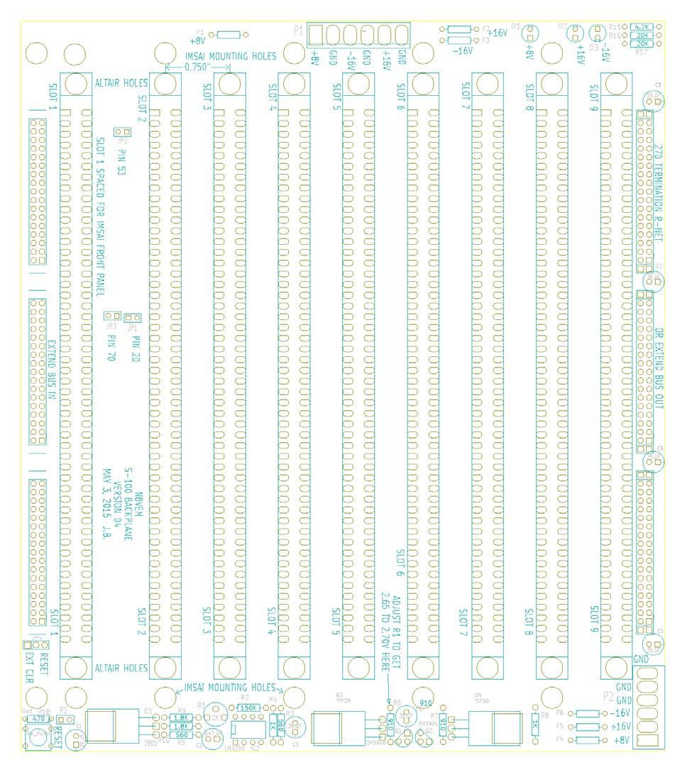
1 N8VEM S-100 BACKPLANE VERSION 04 MAY 3, 2015 J.B. Background. This board is a copy of Andrew Lynch s Version 03 board (with 8 slots) but with added features. Added features: 9 SLOT Active Termination (copied from v 03) 1 st SLOT is spaced 1 from other slots to accommodate IMSAI Style chassis. All other slots are spaced the usual 0.75 Mounting holes for ALTAIR and IMSAI chassis. Hole size (6-32 screws). Two power connectors with different pin outs. o P1 with 0.2 (5.08mm) spacing. Hole Size o P2 with spacing. Hole Size Expansion Connectors with multiple function o Expansion IN/OUT o Test point o Active Termination Jumpers to ground some S-100 pins as needed by IEEE-696. o Pins 20, 53 & 70. (Pin 53 on ALTAIR and IMSAI computers is needed for Front Panel operations and should not be grounded when using these front panels). Thick board, approximately S-100 connectors require 0.25 row spacing. Hole sized Fused power.
2
, but a must have for high speed.")

3 Construction The exact bill of materials will vary based on your desired build. You may choose to install less than all nine of the S-100 connectors. Active Termination is also optional with slower speed systems (4MHz or less), but a must have for high speed. Which power connector you choose is also optional and based upon your ultimate chassis design. Perhaps you already have one size or another of the connector and want to use that. With all the variations, the parts given in the BOM are only a single possibility, your build will vary. Capacitors. The voltage rating on capacitors can be higher than shown; this will not affect the performance in any way. If you are ordering all the capacitors, then it is likely to be cheaper to order all the same voltage (say 16V), further, it will eliminate errors when building. Sometimes a capacitor rated at a higher voltage is actually cheaper than a lower rated one of the same capacitance. This can happen when it is more popular to order that higher voltage, hence production increases and cost per unit decreases. Resistors. All resistors are 1/4Watt. Trimmer pot has 3 leads, spacing between ends and a middle pin that is row offset. Eg. Digikey part number: ND Fuses. These are fast acting Micro Fuses (eg. Digikey Part number: F5580TR-ND). They are optional, you may simply install a jumper wire here if you choose not to use them, or if your power supply already has fused outputs. The exact values of the fuses depend on your S-100 build. Their purpose is to protect the power supply and circuit traces. As a general rule, they should not be higher than the maximum rated current output of your power supply. Here are some reasonable values, but the current demands of the boards you install in your S-100 will ultimately be your best guide. You may also choose to substitute these fuses with PTC type fuses. Fuse Voltage Supply Ratting F1, F4 +8V 3 to 10 Amps F3, F5 +16V 1 Amp F2, F6-16V 1 Amp
4 Base Build BILL OF MATERIALS Part Description Slot1-9 S-100 Connector row spacing P1 6 Position Connector (5.08mm) P2 6 Position Connector F1-F3 Micro fuses for P1 Connector. See text Eg. Digikey p/n: F5580TR-ND F4-F6 Micro fuses for P2 Connector. See Text D1-D3 LED s. Your favorite type. R15 4.7K Resistor R16, 17 20K Resistor JP1-3 2 Pin Pin Header JP1-3 Mini-Jumpers Active Termination Part Description C1,C3 39uF / 25V Tantalum Capacitor C2 0.47uF / 6.3V Tantalum Capacitor C4-C8 39uF / 6.3V Tantalum Capacitor (see text) IC1 LM7805 Voltage Regulator. Positive 5 Volts. TO-220 IC2 LM4250 Op Amp Q1 2N3906 PNP Transistor TO-92 Q2 2N3904 NPN Transistor TO-92 Q3 TIP29 NPN Power Transistor TO-220 Q4 TIP30 PNP Power Transistor TO-220 R1 2K Trimmer POT spacing, row offset Eg Digikey p/n: ND R2 150K Resistor R3,R5 560 Ohm Resistor R4, R8 1K Resistor R6, R7 910 Ohm Resistor R9, R10 1.8K Resistor RN Ohm Resistor Network. 9 pin (8 Resistors Bussed) Reset Switch Part Description SW1 Small tactile PCB Mounted Momentary Push Button Switch R Ohm Resistor P3 2 Pin Pin Header JP4 3 Pin Pin Header Expansion Connectors Part Description Front Connectors 34 pin (2x17) Pin Headers (for Test Pins) Front Connectors 34 pin (2x17) PCB Mounted Ribbon Cable Back Connectors 34 pin (2x17) PCB Mounted Ribbon Cable
5
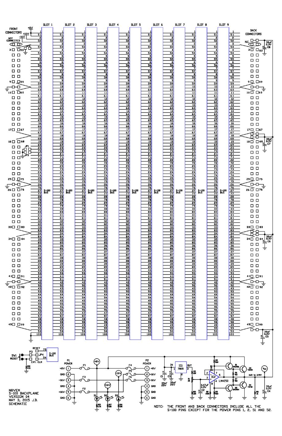
6 The Front expansion connectors can be populated with pin headers as test points or used to extend another backplane board. The back expansion connector can be used to extend or terminate the bus as shown below. Extending the bus on high speed systems (over 4Mhz) might present a problem as the connectors between two backplanes may cause undesired reflections. It has not been tested but the option is there for your choice to try. No guarantees of performance are given. Perhaps one way to minimize the medium transition is to use PCB mounted ribbon cables (eg. Digikey Part number ND) instead of pin headers with connectors & ribbon cables.

7 Eg. Digikey Part Number: ND S-100 Connectors These connectors may be found on Ebay or other Electronic Surplus stores. Ask on the S-100 computer forums for more advice on sourcing these parts.
Schematic Diagram: R2,R3,R4,R7 are ¼ Watt; R5,R6 are 220 Ohm ½ Watt (or two 470 Ohm ¼ Watt in parallel)
") Nano DDS VFO Rev_2 Assembly Manual Farrukh Zia, K2ZIA, 2016_0130 Featured in ARRL QST March 2016 Issue Nano DDS VFO is a modification of the original VFO design in Arduino Projects for Amateur Radio by
Nano DDS VFO Rev_2 Assembly Manual Farrukh Zia, K2ZIA, 2016_0130 Featured in ARRL QST March 2016 Issue Nano DDS VFO is a modification of the original VFO design in Arduino Projects for Amateur Radio by
GLiPIC Ver C Assembly manual Ver 1.0
 GLiPIC Ver C Assembly manual Ver 1.0 Last Rev 1.1 Oct 30, 2001 Author: Ranjit Diol Disclaimer and Terms of Agreement As with any kit, only the individual parts supplied are guaranteed against defects and
Post Tenebras Lab. Written By: Post Tenebras Lab
 Post Tenebras Lab PTL-ino is an Arduino comptaible board, made entirely out of through-hole components. It is a perfect project to learn how to solder and start getting into the world of micro controllers.
Infrared Add-On Module for Line Following Robot
 1 Infrared Add-On Module for Line Following Robot January 3, 2015 Jeffrey La Favre The infrared add-on module allows multiple line following robots to operate on the same track by preventing collisions
Sierra Radio Systems. Making a Keyer with the. HamStack. Project Platform
 Sierra Radio Systems Making a Keyer with the HamStack Project Platform Introduction The HamStack Project Board includes primary interface elements needed to make a high quality CW keyer. Using the LCD
SRI-02 Speech Recognition Interface
 SRI-02 Speech Recognition Interface Data & Construction Booklet The Speech Recognition Interface SRI-02 allows one to use the SR-07 Speech Recognition Circuit to create speech controlled electrical devices.
Sierra Radio Systems. HamStack. Project Board Reference Manual V1.0
 Sierra Radio Systems HamStack Project Board Reference Manual V1.0 Welcome HamStack Project Board Reference Manual Revision 1.0.3 2011 George Zafiropoulos, KJ6VU and John Best, KJ6K This guide provides
12v Power Controller Project Board
 12v Power Controller Project Board 12 Volt Power Controller Introduction This board provides three functions... DC power gate Low voltage disconnect Voltage / current display The typical usage for this
USER S MANUAL VER.1. C10D- PARALLEL PORT INTERFACE CARD BOARD Rev. 1
 USER S MANUAL VER.1 C10D- PARALLEL PORT INTERFACE CARD BOARD Rev. 1 MARCH 2018 User s Manual Page i USER'S MANUAL TABLE OF CONTENTS Contents Page # 1.0 OVERVIEW... iii 2.0 FEATURES... iii 3.0 SPECIFICATIONS...
Storage Card Interface Kit
 Storage Card Interface Kit for MultiMediaCards(MMC) and Secure Digital Cards (SD) MMSD3K The MMSD3K is complete development kit interfaced to a SD or MMC card. This board ideal for projects that involve
ALTAIR 8800 / IMSAI 8080 Replacement CPU Project. Josh Bensadon June 5, 2014 Toronto Canada
 ALTAIR 8800 / IMSAI 8080 Replacement CPU Project Josh Bensadon June 5, 2014 Toronto Canada I cannot thank everyone by name or else I may forget someone, but you know who you are and thank you for your
ES-562/564U COMBINATION CLOCK/TIMER
 142 SIERRA ST., EL SEGUNDO, CA 90245 USA (310)322-2136 FAX (310)322-8127 www.ese-web.com ES-562/564U COMBINATION CLOCK/TIMER OPERATION AND MAINTENANCE MANUAL The ES-562U/564U is a combination six digit
UF-3701 Power Board Construction Guide
 Page 1/5 Soldering and Part Placement See the Chapter 3 of the MIT 6270 Manual for information on electronic assembly, including soldering techniques and component mounting. Construction Information All
Optional IOB31 Board. x1 PCIe Link* (Expansion) x16 PCIe Link* (A0) PCI-X. 64-bit/66MHz. Connectors (A1, A2, A3, A4) PCI-X. x4 PCIe Link (B0) PCI-X
 x16 PCIe Link* (A0) PCI-X. 64-bit/66MHz. Connectors (A1, A2, A3, A4) PCI-X. x4 PCIe Link (B0) PCI-X") Technical Information Jumpers and Connectors BPG () Graphics-Class Express Backplane Block Diagram Connectors (P & P) Ethernet Connectors (P & P) PICMG. System Host Board BPG Backplane System Host Board
Technical Information Jumpers and Connectors BPG () Graphics-Class Express Backplane Block Diagram Connectors (P & P) Ethernet Connectors (P & P) PICMG. System Host Board BPG Backplane System Host Board
RC-210 Repeater Controller Assembly Manual
 Arcom Communications 24035 NE Butteville Rd Aurora, Oregon 97002 (503) 678-6182 arcom@ah6le.net RC-210 Repeater Controller Assembly Manual Hardware Version 3.0 Original Release Date September 13, 2004
Altair 8800b Restoration
 Altair 8800b Restoration I purchased this Altair 8800b through ebay. This is a very heavy computer, especially in the corner with the enormous transformer. Unfortunately, the seller shipped the computer
Pacific Antenna Easy TR Switch Kit
 Pacific Antenna Easy TR Switch Kit Kit Description The Easy TR Switch is an RF sensing circuit with a double pole double throw relay that can be used to automatically switch an antenna between a separate
Construction Construction Instructions
 Semi-Virtual Diskette SVD Construction Construction Instructions PCB version 2.0 September 2004 Eric J. Rothfus Table of Contents Table of Contents... i Parts List...1 Construction Overview...5 PCB Construction...
Bill of Materials: 8x8 LED Matrix Driver Game PART NO
 8x8 LED Matrix Driver Game PART NO. 2171031 This Game Maker II kit is a game design platform using a single color 8x8 matrix LED without the need for a shift register or expensive Arduino. The kit includes
CV Arpeggiator Rev 2 Build Documentation.
 CV Arpeggiator Rev Build Documentation. Last updated 8-0-03 The CV Arpeggiator is a modular synth project used for creating arpeggios of control voltage. It utilizes a custom programmed PIC 6F685 micro
Installation/assembly manual for DCC/Power shield
 Installation/assembly manual for DCC/Power shield The DCC circuit consists of the following components: R1/R6 R2/R3 R4/R5 D1 C2 2 kω resistor ½ Watt (colour code Red/Black/Black/Brown/Brown) 10 kω resistor
RC-210 Repeater Controller Assembly Manual
 Arcom Communications 24035 NE Butteville Rd Aurora, Oregon 97002 (503) 678-6182 arcom@ah6le.net RC-210 Repeater Controller Assembly Manual Hardware Version 2.5 Reproduction or translation of any part of
Shack Clock kit. U3S Rev 2 PCB 1. Introduction
 Shack Clock kit U3S Rev 2 PCB 1. Introduction Thank you for purchasing the QRP Labs Shack Clock kit. This clock uses the Ultimate3S QRSS/WSPR kit hardware, but a different firmware version. It can be used
Images Scientific OWI Robotic Arm Interface Kit (PC serial) Article
 Article") Images Scientific OWI Robotic Arm Interface Kit (PC serial) Article Images Company Robotic Arm PC Interface allows real time computer control and an interactive script writer/player for programming and
Images Scientific OWI Robotic Arm Interface Kit (PC serial) Article Images Company Robotic Arm PC Interface allows real time computer control and an interactive script writer/player for programming and
Modular Backplane For RC2014 User Guide
 Modular Backplane For RC204 User Guide For module: SC2 version.0 Design and Documentation by Stephen C Cousins Edition.0. CONTENTS OVERVIEW...2 PRINTED CIRCUIT BOARD... 4 SCHEMATIC... 8 WHAT YOU NEED...9
AVR-M Rev 5 ASSEMBLY
 AVR-M Rev 5 ASSEMBLY The AVR_M is a very compact self contained Atmel AVR mcu controller board. It includes an onboard serial programmer (via PC com port), an I2C eeprom and can use a Mega163, Mega16 or
Description. Overview. Features S90-MTM-DEV-2. MTM Development Board 2.0 Datasheet
 Overview The Acroname Development Board 2.0 (-DEV-2), part of Acroname s (Manufacturing Test Module) product series, is a connectivity solution designed for development or integration to wire-based testers.
Rapid40i PIC Prototyping PCB User Manual
 Description This is a PCB designed to facilitate the rapid prototyping of a device based on a 40 pin Microchip PIC microcontroller. To allow users to focus on their application, we take care of key housekeeping
Modular Backplane For RC2014 User Guide
 Modular Backplane For RC204 User Guide For module: SC05 version.0 Design and Documentation by Stephen C Cousins Edition.0.0 CONTENTS OVERVIEW...2 PRINTED CIRCUIT BOARD... 4 SCHEMATIC... 6 WHAT YOU NEED...7
Reverse DDS Kit Construction
 Reverse DDS Kit Construction This kit is only recommended for home constructors experienced with Surface Mount construction so these notes are for guidance only. Mark out and drill the holes for the SMA
Tone Bender Mk III. Grandaddy of super-cool vintage fuzz tone
 Tone Bender Mk III Grandaddy of super-cool vintage fuzz tone Contents of this document are 2014 Pedal Parts Ltd. No reproduction permitted without the express written permission of Pedal Parts Ltd. All
Storage Card Interface Kit
 Storage Card Interface Kit for MultiMediaCards(MMC) and Secure Digital Cards (SD) MMSD3F The MMSD3K is complete development kit interfaced to a SD or MMC card. This board ideal for projects that involve
HUB-ee BMD-S Arduino Proto Shield V1.1
 HUB-ee BMD-S Arduino Proto Shield V1.1 User guide and assembly instructions Document Version 0.5 Introduction & Board Guide 2 Schematic 3 Quick User Guide 4 Assembly Guide 6 Kit Contents 7 1) Diodes and
DSP Filter System. Author: Nels Pearson Org Date: July 5, 2007 Rev Date: July 6, Doc Number: AIGO-009
 DSP Filter System Author: Nels Pearson Org Date: July 5, 2007 Rev Date: July 6, 2007 Doc Number: AIGO-009 2-13 Table of Contents Introduction...3 Overview...3 A2D Input Filter Board...4 Overview...4 Input
PropIO V2 User Guide. Wayne Warthen RetroBrew Computers
 PropIO V2 User Guide Wayne Warthen RetroBrew Computers August 25, 2017 Contents Summary... 2 Architecture... 3 Compatibility... 5 Construction... 5 Configuration... 8 Connectors... 8 Testing... 8 Usage...
Obsolete. LX1800 SMBus TO ANALOG INTERFACE
 LX1800 SMBus TO ANALOG INTERFACE TM Page 1 INTRODUCING TO PRODUCT The LX1800 Evaluation Board is available from for evaluating the functionality and performance of the LX1800 SMBus to Analog Interface
C S Technology Ltd. cstech.co.uk. DTMF display 32 kit with 2 line x 16 LCD display
 C S Technology Ltd cstech.co.uk DTMF display 32 kit with 2 line x 16 LCD display Our DTMF display can display up to 32 characters (16 per line). The display can be cleared by a button (not supplied) or
Rapid28iXL PIC Prototyping PCB User Manual
 Description Features This is a PCB designed to facilitate the rapid prototyping of a device based on a 28 pin Microchip PIC microcontroller. To allow users to focus on their application, we take care of
RC210 Repeater Controller Assembly Manual
 Arcom Communications 24035 NE Butteville Rd Aurora, Oregon 97002 (503) 678-6182 arcom@ah6le.net http://www.arcomcontrollers.com/ RC210 Repeater Controller Assembly Manual Hardware Version 3.3 Reproduction
Power LED Driver. By Dushan Grujich, on February 14 th. 2014
 Power LED Driver By Dushan Grujich, on February 14 th. 2014 Most often microscope enthusiasts encounter a problem when converting their microscope illuminator from incandescent lamp to a power LED. Problem
Moog Components Group Submux1 Manual December 7, 2009
 RS-232 Submux Motherboard (P/N 970381-xxx) and Daughter-cards (4 ch. RS-232 P/N 970391-xxx, 4ch. RS-485 / 2 ch. RS422 P/N 980430-xxx, and Trigger Interface P/N 200700-XXX) User s Manual And Troubleshooting
Rapid40iXL PIC Prototyping PCB User Manual
 Description This is a PCB designed to facilitate the rapid prototyping of a device based on a 40 pin Microchip PIC microcontroller. To allow users to focus on their application, we take care of key housekeeping
2562 QUICK START GUIDE
 2562 QUICK START GUIDE CTI P/Ns: 2562 Quick Start Guide: 062-00348-010 2562 Installation and Operation Guide: 062-00332-011 Summary: The 2562 is designed to translate a digital word from the programmable
University of Florida EEL 4744 Drs. Eric M. Schwartz, Karl Gugel & Tao Li Department of Electrical and Computer Engineering
 Page 1/9 Revision 1 OBJECTIVES In this document you will learn how to solder and to debug a board as you are building it. REQUIRED MATERIALS Website documents o UF 68HC12 Development Board Manual (board
DEV-1 HamStack Development Board
 Sierra Radio Systems DEV-1 HamStack Development Board Reference Manual Version 1.0 Contents Introduction Hardware Compiler overview Program structure Code examples Sample projects For more information,
Table 1 shows all the different variations of output modules available.
 This application note will show how to configure the LPM409 / LPM616 modular supplies in a series and parallel connection scheme. For a serial connection scheme see Figure 1. For a parallel connection
PBP-06V4. Horizontal 4 PCI/2 PICMG Passive Backplane. Introduction. Design Philosophy
 PBP-06V4 T Horizontal 4 PCI/2 PICMG Passive Backplane He PBP-06V4 backplane is fully PICMG Rev 2.1 compliant. It is a member of PBP s PCI product family and is intended to support all PICMG compliant boards
TACH-ROTOR ADAPTER PLUS
 The Tach-Rotor Adapter Plus (TRA PLUS) works with 3-wire 12VDC fans commonly found in computers, computer power supplies, uninterruptable power supplies, DVRs, servers, and other electrical equipment with
MX Educational Target User Manual
 MX Educational Target User Manual Revision History Date Description Initial release. Table of Contents 1. Introduction... 4 1.1. Module Models... 4 1.2. Package Contents... 4 1.3. Key Hardware Features...
FX-2 Control Board ASY-360-XXX Setup and Configuration Guide
 FX-2 Control Board ASY-360-XXX Setup and Configuration Guide Micro Air Corporation Phone (609) 259-2636 124 Route 526. WWW.Microair.net Allentown NJ 08501 Fax (609) 259-6601 Table of Contents Introduction...
アナログ. D/500 FET Limiter PCB Overlay, Schematic and Bill of Materials mnats
 アナログ D/500 FET Limiter PCB Overlay, Schematic and Bill of Materials 2014 mnats LED1 LED2 Q1_ALT Q11_ALT R23 IC1 R55 R56 GR SIG +VR -VR -V IN VU SIG 0 ADJ Q6 ST LNK SW1 SW3 R21 R61 R4 R5 R7 R10 R6 R8 C1
Homework 5: Circuit Design and Theory of Operation Due: Friday, February 24, at NOON
 Homework 5: Circuit Design and Theory of Operation Due: Friday, February 24, at NOON Team Code Name: Motion Tracking Laser Platform Group No.: 9 Team Member Completing This Homework: David Kristof NOTE:
ON4AKH Antenna Rotator controller Version 1.0
 ON4AKH Antenna Rotator controller Version 1.0 1. Some construction tips The project consists out of 3 boards. The 1 st board is the main board containing the PIC micro controller and the H-bridge components
Exclusive 2.5 GHz Frequency Counter
 Exclusive 2.5 GHz Frequency Counter with blue 2 x 16 LCD display This manual will guide you how to assemble, test and tune this frequency counter KIT. Features: Frequency range from 5 MHz to 2.5GHz Factory
Sandevices E681 RGB Pixel Controller Assembly Manual
 Sandevices E681 RGB Pixel Controller Assembly Manual Oct 22, 2011 Oct 30, 2011 Initial Release Added component illustrations, silkscreen images, and misc text changes Prior electronic assembly experience
アナログ. A/500 FET Limiter PCB Overlay, Schematic and Bill of Materials mnats
 アナログ A/500 FET Limiter PCB Overlay, Schematic and Bill of Materials 2014 mnats LED1 LED2 Q1_ALT Q11_ALT R23 IC1 R55 R56 GR SIG +VR -VR -V IN VU SIG 0 ADJ Q6 ST LNK SW3 SW1 R21 R61 R4 R5 R7 Q1 R8 C2 C6
Bill of Materials D RF INTERFACE CCA G. Assembly No.: Description: Revision:
 D161020 RF INTERFACE CCA Designator Item Part Number Qty UOM Description Engineering Description TB2-TB5 19B1547-002 4 EA CONNECTOR, HEADER 2P PC HEADER J4 19B1547-003 1 EA CONNECTOR, HEADER 3P PC HEADER
Fuzz Face. Vintage fuzz with optional voltage inverter
 Fuzz Face Vintage fuzz with optional voltage inverter Contents of this document are 2014 Pedal Parts Ltd. No reproduction permitted without the express written permission of Pedal Parts Ltd. All rights
ARES 2 Tone Sequential Tone Decoder Kit Assembly Instructions
 Tools Required: ARES Tone Sequential Tone Decoder Kit Assembly nstructions 3/8 Electric Drill Soldering ron Wire Strippers Needle Nose Pliers Wire Cutters Ruler 60/40 Solder Phillips Screw Driver /8, 5/64,
MAIN PCB (The small one)
") THANKS FOR CHOOSING ONE OF OUR KITS! This manual has been written taking into account the common issues that we often find people experience in our workshops. The order in which the components are placed
THANKS FOR CHOOSING ONE OF OUR KITS! This manual has been written taking into account the common issues that we often find people experience in our workshops. The order in which the components are placed
PAS 9737/AI-SMT ENGINEERING SPECIFICATION
 Document PAS54 Spec Revision C (7/3/8) PAS 9737/AI-SMT ENGINEERING SPECIFICATION 64 CHANNEL, 6 BIT VME ANALOG INPUT CARD PCB Revision D (7/3/8) Additional copies of this manual or other Precision Analog
USB Connectors. Optional IOB31 Board. *Assumes Trenton Server-Class system host board. x4 PCIe Link* (Expansion) x8 PCIe. Connector.
 x8 PCIe. Connector.") 0 Carroll Canyon Rd San Diego, CA 9 Phone () 0 Fax () www.chassisplans.com Technical Information Jumpers and ss BP0 (S0) ServerClass PCI Express Backplane Block Diagram USB s (P & P) Ethernet s (P & P)
0 Carroll Canyon Rd San Diego, CA 9 Phone () 0 Fax () www.chassisplans.com Technical Information Jumpers and ss BP0 (S0) ServerClass PCI Express Backplane Block Diagram USB s (P & P) Ethernet s (P & P)
3-slot Backplane For RC2014 User Guide
 3-slot Backplane For RC204 User Guide For module: SC6 version.0 Design and Documentation by Stephen C Cousins Edition.0.0, 208-0-7 CONTENTS OVERVIEW...2 PRINTED CIRCUIT BOARD... 4 SCHEMATIC... 6 WHAT YOU
Electronic Coin Toss
 1 Electronic Coin Toss Why this circuit? This circuit was not designed for people who can make up their mind nor have a coin to use for a heads or tail coin toss. This circuit can also be used to ask it
VG-305A AC Traffic Light Controller Kit
 Galak Electronics Electronic kits and components Website: GalakElectronics.com Email: sales@galakelectronics.com Phone: (302) 832-1978 VG-305A AC Traffic Light Controller Kit Thank you for your purchase
ES-362U PRESETTABLE MASTER TIMER
 142 SIERRA ST., EL SEGUNDO, CA 90245 USA (310)322-2136 FAX (310)322-8127 www.ese-web.com ES-362U PRESETTABLE MASTER TIMER OPERATION AND MAINTENANCE MANUAL The ES-362U is a four digit, presettable 100 minute
CDN502 HIGH DENSITY I/O ADAPTER USER GUIDE
 CDN502 HIGH DENSITY I/O ADAPTER USER GUIDE 13050201 (c) Copyright DIP Inc., 1996 DIP Inc. P.O. Box 9550 MORENO VALLEY, CA 92303 714-924-1730 CONTENTS DN502 PRODUCT OVERVIEW 1 DN502 INSTALLATION 1 POWER
EBF31A Assembly Instructions
 EBF31A Assembly Instructions Revision v0.2 07/09/2014 Seth Neumann, sneumann@pacbell.net Introduction This document describes the functional blocks of the EBF31A and how to assemble it. Revision History
Building RoboPIC 18F4550
 RoboPIC 8F4550 Copyright 206 William Henning Building RoboPIC 8F4550 Copyright 206 William Henning RoboPIC 8F4550 build manual v0.90 The most up to date documentation will always be available at: http://www.mikronauts.com/robot-controllers/robopic-8f4550/
PICMG 1.3 System Host Board x8 PCIe Link (A2) x8 PCIe Link (A0) x4 PCIe Link. x4 PCIe Link. x4 PCIe Link. PCIe Link (B0) 24 Lane.
 x8 PCIe Link (A0) x4 PCIe Link. x4 PCIe Link. x4 PCIe Link. PCIe Link (B0) 24 Lane.") 0 Centennial Drive Gainesville, Georgia 00 Sales (00) -0 Phone (0) -00 Fax (0) -0 Technical Information Jumpers and s BPX0 (0) Server-Class PCI Express Backplane Block Diagram USB s (P & P) PICMG. System
0 Centennial Drive Gainesville, Georgia 00 Sales (00) -0 Phone (0) -00 Fax (0) -0 Technical Information Jumpers and s BPX0 (0) Server-Class PCI Express Backplane Block Diagram USB s (P & P) PICMG. System
Luxman DML replacement manual by PE1MMK (construction)
") Luxman DML replacement manual by PE1MMK (construction) 1. Dismantling Take your amplifier to a appropriate place to work on it, use a small cloth or plastic cover to place your amp on, otherwise you might
Luxman DML replacement manual by PE1MMK (construction) 1. Dismantling Take your amplifier to a appropriate place to work on it, use a small cloth or plastic cover to place your amp on, otherwise you might
H89-Z37 DOUBLE-DENSITY FLOPPY CONTROLLER
 H8-Z37 DOUBLE DENSITY FLOPPY CONTROLLER 2015 H89-Z37 DOUBLE-DENSITY FLOPPY CONTROLLER Norberto Collado norby@koyado.com 6/6/2015 Revision History and Disclaimer Revision History Revision Date Comments
Proto-DB (#28310): Prototyping Daughterboard
: Prototyping Daughterboard") Web Site: www.parallax.com Forums: forums.parallax.com Sales: sales@parallax.com Technical: support@parallax.com Office: (916) 624-8333 Fax: (916) 624-8003 Sales: (888) 512-1024 Tech Support: (888) 997-8267
Web Site: www.parallax.com Forums: forums.parallax.com Sales: sales@parallax.com Technical: support@parallax.com Office: (916) 624-8333 Fax: (916) 624-8003 Sales: (888) 512-1024 Tech Support: (888) 997-8267
EL Wire sequencer / power supply PART NO
 EL Wire sequencer / power supply PART NO. 2206213 The EL Wire sequencer is a EL wire power supply capable of powering 50 plus feet of 2.6mm El Wire and 8 ports controlled by a BS2sx. A menu driven command
PIC 28 Pin Board Documentation. Update Version 5.0
 PIC 28 Pin Board Documentation Update 2009.10 Version 5.0 Table of Contents PIC 28 Pin Board Documentation... 1 Table of Contents... 2 Introduction... 3 Circuit Schematic... 4 The following is the Circuit
LCD Prototype Circuit on Solderless Breadboard. 840 Pin Solderless Breadboard (http://www.digikey.com/ # ND)
") Solderless Breadboard Tutorial Cornerstone Electronics Technology and Robotics I Week 3 Solderless Breadboards: o Solderless breadboards are commonly used in experimentation or to make a prototype of a
Solderless Breadboard Tutorial Cornerstone Electronics Technology and Robotics I Week 3 Solderless Breadboards: o Solderless breadboards are commonly used in experimentation or to make a prototype of a
4.0 Blue LED DCF77 Clock documentation
 4.0 Blue LED DCF77 Clock documentation 1. LED Clock Main Board PCB mounting: Mount and solder the eight wire bridges. Mount and solder resistors R16, R18, R20, R22. Mount and solder capacitors C1 C3 (pitch
FX-2 Control Board ASY-360-XXX Setup and Configuration Guide
 FX-2 Control Board ASY-360-XXX Setup and Configuration Guide Micro Air Corporation Phone (609) 259-2636 124 Route 526. WWW.Microair.net Allentown NJ 08501 Fax (609) 259-6601 Table of Contents Introduction...
Flight Data Recorder Hardware Version 1.0
 Flight Data Recorder Hardware Version 1.0 By R. G. Sparber Scope The Flight Data Recorder (FDR) hardware is described here. The software is described in a separate document. The reader can etch their own
Flexible 32-bit PCI to MiniPCI Express Adapter
 About this Document Flexible 32-bit PCI to MiniPCI Express Adapter Hardware Manual June 01, 2011 Revision 1.1 Page 1 About this Document Contents 1 About this Document... 4 1.1 Purpose... 4 1.2 Feedback...
Blue Point Engineering
 Blue Point Engineering Board - Pro Module (E) Instruction Pointing the Way to Solutions! Controller I Version 2.1 The Board Pro E Module provides the following features: Up to 4 minutes recording time
Arduino shield kit. 1) Low Pass Filter (LPF) kit (available for LF/MF/HF/VHF bands 2,200m to 6m)
 Low Pass Filter (LPF) kit (available for LF/MF/HF/VHF bands 2,200m to 6m)") Arduino shield kit 1. Introduction The QRP Labs Arduino shield kit is a versatile shield that can be used for various purposes. Write your own Arduino sketch to define the functionality! For example: 1)
Arduino shield kit 1. Introduction The QRP Labs Arduino shield kit is a versatile shield that can be used for various purposes. Write your own Arduino sketch to define the functionality! For example: 1)
USER S MANUAL VER.1. C10- PARALLEL PORT INTERFACE CARD BOARD Rev. 11
 USER S MANUAL VER.1 C10- PARALLEL PORT INTERFACE CARD BOARD Rev. 11 FEBRUARY, 2017 User s Manual Page i USER'S MANUAL TABLE OF CONTENTS Contents Page # 1.0 OVERVIEW... iii 2.0 FEATURES... iii 3.0 SPECIFICATIONS...
Achieving EMV Electrical Compliance with the Teridian 73S8024RN
 August 2005 Achieving EMV Electrical Compliance with the Teridian 1 Introduction This application note highlights particular testing considerations required to achieve compliance for payment systems smart
DMX512-4 Channel PWM Driver Board #805
 DMX512-4 Channel PWM Driver Board #805 Overview The 4-channel PWM driver board provides four open drain (collector) type outputs that can be directly controlled from a DMX512 network. The four channels
BASIC Stamp Activity Board: Features and Specifications
 27905 w / Power Supply 27906 w/o Power Supply BASIC Stamp Activity Board: Features and Specifications The BASIC Stamp Activity Board (BSAC) is a demonstration board for Parallax BASIC Stamp computers (BS1-IC,
Transcendent Frequency Counter
 Transcendent Frequency Counter with blue 2 x 16 LCD display This manual will guide you how to assemble, test and operate this frequency counter KIT. Features: The transcendent counter has two input channels
MAIN PCB (The small one with the square cut out from one side)
") THANKS FOR CHOOSING ONE OF OUR KITS! This manual has been written taking into account the common issues that we often find people experience in our workshops. The order in which the components are placed
THANKS FOR CHOOSING ONE OF OUR KITS! This manual has been written taking into account the common issues that we often find people experience in our workshops. The order in which the components are placed
Manual Main PCB Small-MIDI 4
 Index PARTLIST MAIN PCB... 2 INTRODUCTION... 3 GENERAL... 3 THE CIRCUIT... 3 ASSEMBLY KIT... 4 ASSEMBLY OF THE PCB... 4 An important tip...... 4 ASSEMBLY... 4 THE CONNECTORS... 4 Power supply J1... 4 IDC
Construction Manual for the W0EB/N5IB New ubitx Raduino Clone
 Construction Manual for the W0EB/N5IB New ubitx Raduino Clone Version 1.5, January 09, 2019 Manual and Images Copyright W0EB and N5IB August 03. 2018, all rights reserved. May be freely reproduced and
DYNAMIC ENGINEERING 150 DuBois St. Suite 3, Santa Cruz, Calif Fax Est.
 DYNAMIC ENGINEERING 150 DuBois St. Suite 3, Santa Cruz, Calif. 95060 831-457-8891 Fax 831-457-4793 http://www.dyneng.com sales@dyneng.com Est. 1988 User Manual PCI2PMC PCI Single Slot PMC Compatible Carrier
Altera EP4CE6 Mini Board. Hardware User's Guide
 Altera Hardware User's Guide 1. Introduction Thank you for choosing the! is a compact FPGA board which is designed based on device. It's a low-cost and easy-to-use platform for learning Altera's Cyclone
Mini4 Tritech/Trigger Daughterboard (P/N xxx) User s Manual And Troubleshooting Guide
 User s Manual And Troubleshooting Guide") Mini4 Tritech/Trigger Daughterboard (P/N 201600-xxx) User s Manual And Troubleshooting Guide February 23, 2009 Revision C Moog Components Group Springfield Operations 750 West Sproul Road Springfield,
Mini4 Tritech/Trigger Daughterboard (P/N 201600-xxx) User s Manual And Troubleshooting Guide February 23, 2009 Revision C Moog Components Group Springfield Operations 750 West Sproul Road Springfield,
Evaluation Board for AD5371 EVAL-AD5371EBZ
 Preliminary Technical Data FEATURES Full-Featured Evaluation Board for the AD5371 USB Interface PC Software for Register Programming Various Reference Voltages Available Stand-Alone Operation INTRODUCTION
PWR-I/O-DB Power and I/O Daughterboard (#28301)
") Web Site: www.parallax.com Forums: forums.parallax.com Sales: sales@parallax.com Technical: support@parallax.com Office: (916) 624-8333 Fax: (916) 624-8003 Sales: (888) 512-1024 Tech Support: (888) 997-8267
Web Site: www.parallax.com Forums: forums.parallax.com Sales: sales@parallax.com Technical: support@parallax.com Office: (916) 624-8333 Fax: (916) 624-8003 Sales: (888) 512-1024 Tech Support: (888) 997-8267
Bill of Materials: Picaxe-based IR Control Module Pair PART NO
 Picaxe-based IR Control Module Pair PART NO. 2171014 The IRGEII is an IR (Infra Red) Transmitter and Receiver pair that uses a 38 KHZ frequency of invisible light to communicate simple instructions. The
Massachusetts Institute of Technology Department of Electrical Engineering and Computer Science Introductory Digital Systems Laboratory
 Massachusetts Institute of Technology Department of Electrical Engineering and Computer Science 6.111 -- Introductory Digital Systems Laboratory NUBUS LABORATORY KIT For your pleasure and convenience,
KPIC-0818P (V050919) Devices Included in this Data sheet: KPIC-0818P
 Devices Included in this Data sheet: KPIC-0818P") Devices Included in this Data sheet: KPIC-0818P Features: Carefully designed prototyping area Accepts 8 pin PIC12 series micro-controllers Accepts 14 and 18 Pin PIC16 series Accepts some 8,14 and 18 pin
Devices Included in this Data sheet: KPIC-0818P Features: Carefully designed prototyping area Accepts 8 pin PIC12 series micro-controllers Accepts 14 and 18 Pin PIC16 series Accepts some 8,14 and 18 pin
Sidewinder Development Board rev 1.0
 33 Sidewinder Development Board rev 1.0 Features Altera MAX V CPLD 5M160ZT100C5 JTAG programmable USB programmable USB powered 12 On board LEDs 10 on board switches 3 RGB LEDs One 40 pin expansion headers
4.1 Parts and Components... IV Assembly Tips... IV Assembly Precautions... IV Required Tools, Equipment and Materials..
 IV PERSONALITY MODULE ASSEMBLY 4.1 Parts and Components............ IV-1 4.2 Assembly Tips............... IV-1 4.3 Assembly Precautions............ IV-1 4.4 Required Tools, Equipment and Materials.. IV-1