Locktronics PICmicro getting started guide
|
|
|
- Joel Gray
- 5 years ago
- Views:
Transcription
1
2 Page 2 getting started guide What you need to follow this course 2 Using the built-in programs 3 Create your own programs 4 Using Flowcode - your first program 5 A second program 7 A third program 8 Other programming issues 9 Driver installation procedure 11 Device specification 12

 carriers 1 x 10k variable resistor")

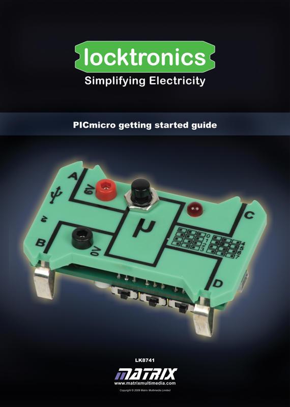
3 Page 3 What you need What you need to follow the examples in this document: 1. The Locktronics microcontroller carrier and USB cable: This uses a PIC 18F2455 microcontroller. It behaves just like a normal microcontroller - but when you plug the USB lead in and press the reset switch you can send a new program to the device. p2b 2. A Locktronics baseboard, and the following component carriers: 1 x power-supply carrier 2 x slide switch carriers 2 x LED (5V) carriers 1 x 10k variable resistor carrier 2 x 10k resistor carriers 3. A DC Power supply: The mains-powered DC power supply can be adjusted to give output voltages of 3V, 4.5V, 6V, 7.5V, 9V or 13.5V, with currents typically up to 1A. The voltage is changed by turning the selector dial on the back of the supply until the arrow points to the required voltage. The Locktronics PICmicro device must use the 6V supply setting. p2a The Locktronics DC power supply carrier requires a polarity of a positive inner and negative outer. p2c

 Program 1 - The bank problem (Programmable logic gate) Program 2 - Fridge alarm")
 Program 4 - Car alarm (Monostable and Astable functions) Program 5 - Decorative lights (Sequence generator) Program 6 - General purpose timer Program 7 - General purpose signal")
4 Page 4 Accessing the built in programs Using the built-in programs: The Locktronics microcontroller comes with eight programs already written into its memory. (Actually, this is one program which starts with a menu that allows you to select from what amounts to eight programs.) Reset switch The programs are numbered from 0 to 7 (rather than from 1 to 8) to correspond with the positions of the three selector switches. The table opposite makes this clearer: The built-in programs are: Program 0 - Burglar alarm (3-inputAND gate) Program 1 - The bank problem (Programmable logic gate) Program 2 - Fridge alarm (Thermistor control) Program 3 - Keep cool! (Motor speed control) Program 4 - Car alarm (Monostable and Astable functions) Program 5 - Decorative lights (Sequence generator) Program 6 - General purpose timer Program 7 - General purpose signal generator. Selector switches p3c p3b To select one of these programs: set the switches to the correct position for the program you require, (using the table as a guide); connect a 6V power supply to the power sockets on the carrier, as shown in the picture below; press the Reset switch. p3a How to connect the power supply to the Locktronics microcontroller carrier.
 loaded onto your computer. This is used to design your PIC program, and simulate it on-screen.")

5 Page 5 Developing your own programs Create your own programs: You can create your own programs, download them to the Locktronics microcontroller carrier, and use them in a circuit. You will need Flowcode (v3.6, v4.2 or later) loaded onto your computer. This is used to design your PIC program, and simulate it on-screen. There is a free version of the program that you can use to develop and download programs. The free version is limited to 50 flowchart icons. When the program does what you want, you download the program to the Locktronics microcontroller, via a USB cable. Flowcode converts the program into code for the PIC microcontroller on the Locktronics microcontroller carrier, which is preprogrammed with software that allows you to send a new program via USB. You will find detailed instructions on how to install Flowcode in the Flowcode Getting Started guide at Note that if you want to use the PIC for the Microcontrolelr systems course again you will need to reload the original program. p4a p4b The PIC microcontroller: Here is the pin-out for the 28 pin 18F2455 microcontroller. The Locktronics microcontroller uses only four of the Input / Output terminals on the PIC chip, marked as A, B, C and D on the pinout. Any of these can be configured to act as an input, to transfer information from sensors in the outside world to the microcontroller, or to act as an output, and transfer the results of a program from the microprocessor to actuators in the outside world. However, the Locktronics carrier is designed with certain functions in mind: Terminals A and B are connected to two of the analogue-capable inputs, AN0 and AN1 on A. The built-in analogue-to-digital converter (ADC) generates a digital signal from the analogue voltage applied to these inputs. Terminals C and D can be used to send pulse-width modulated (PWM) signals (alternating rapidly between on and off,) to devices such as motors and bulbs, to control their speed / brightness, respectively.


6 Page 6 Using Flowcode Using Flowcode: You will find step-by-step instructions on how to use Flowcode in the Flowcode Getting Started guide at Your first program: p5a We start with a simple program, to light a LED when a switch is pressed. Open the Flowcode application. Click on the New program icon, at the left-hand end of the toolbar. The Choose a Target dialogue box opens. Scroll down the list of PIC targets and select LocktronicsPIC. V3 components can be found in the component toolbar. V4 components can be found under the common toolbar item. p5b p5e p5c V3 V4 Set up the components in the panel: 1. The switch: Add a switch component to the program. Right click the switch component and choose component connections from the pop up menu. Use this to connect the switch to PORT A bit 0, (which is terminal A on the Locktronics carrier.) p5f 2. The LED: Add a LED component to the program. Right click the LED component and choose component connections from the pop up menu. Use this to connect the LED to PORT C bit 1 (terminal C on the Locktronics carrier.) p5d


7 Page 7 Using Flowcode Drag a loop icon onto the program panel between the Begin and End icons. Then drag an input icon below the loop icon and an output icon below that. Configuring the icons: Click on Edit in the menu at the top of the Flowcode window. Click on Variables... to open the Variable Manager dialogue box. Click on Add New Variable.... A new dialogue box opens. Type in the name input for the new variable, and accept the Byte type. Click OK, and close the Variable Manager box. Double-click on each of the icons in turn to open the Properties dialogue boxes. Configure the icons as follows: Save the Flowcode program. p6b Display name Repeat Loop while 1 Test Loop at the Start p6a Display name Read the switch Variable input PORT A Input from Single Bit 0 Display name Make it control the LED Variable input PORT C Output to Single Bit 1 Simulate the program: Click on Run in the menu, and select the Step Into option. The Begin icon has a red box around it. Each time you press the F8 key, the red box moves down to the next icon. In this way, the program is simulated step-by-step. When the red box returns to the top of the While loop, click on the switch image to switch it on. Continue pressing the F8 key to see the effect of this change. Then click on the switch again to switch it off, and see what effect this has when you simulate the program. Stop the simulation using either the blue square on the Tools menu, or the Stop option in the Run menu. Compile the program: Connect the Locktronics microcontroller to the computer using the USB lead. Click on Chip in the menu. Select the Compile to chip... option. First of all, this converts the program into the C programming language, and from there into Assembler. Finally it produces the binary code needed by the PIC microcontroller, and passes this via the USB lead to the chip. The program can now be tested on the Locktronics baseboard.

 p7a Try this: Modify the program so that the switch lights two LEDs, connected to C bit 1 (terminal C) and C bit 2 (terminal D).")


8 Page 8 Using Flowcode Build the circuit: The picture shows one way to build the circuit. Notice the red and black leads that connect the microcontroller to the power supply. The switch is connected to the 0V power rail by a 10kΩ resistor, (though the actual value is not important - any value of a few kω will do.) p7a Try this: Modify the program so that the switch lights two LEDs, connected to C bit 1 (terminal C) and C bit 2 (terminal D). A second program: p7b This time, your program will make the LED flash. The Flowcode program is shown on the right. Some of the icon configuration is the same as last time and is not listed below. The new icons are configured in the same way, using the details given below: Display name If: Is it on? input=1 Display name Switch LED on Value 1 PORT C Output to Single Bit 1 Display name Delay value Wait 1 sec 1 second Display name Switch LED off Value 0 PORT C Output to Single Bit 1 Simulate and compile the program in the same way as before. The circuit layout is exactly the same. Try this: Modify the program so that: the LED flashes twice as fast; the LED turns on and stays on for 5 seconds when the switch is closed, (but does not flash.)


9 Page 9 Using Flowcode A third program: The aim is to make the microcontroller behave as an AND gate, and so output a logic 1 signal (and light the LED) only when both switch A AND switch B are closed. The Flowcode program is shown on the right. You need to create three new variables, called switcha, switchb and result. Look back at page 6 if you can t remember how to do this. The new icons are configured in the same way as before. The text boxes that follow should help with the configuration: Display name Read switch A Variable switcha PORT A Input from Single Bit 0 p8a Display name Read switch B Variable switchb PORT A Input from Single Bit 1 Display name Calculation Check for AND result = switcha AND switchb Display name Output Variable result PORT C Output to Single Bit 1 Simulate and compile the program in the same way as before. The circuit layout needs a second switch unit (i.e. switch and 10kΩ resistor,) with the junction between them connected to terminal B ( A bit 1.) One way to do this is shown in the picture. p8b Try this: Modify the program so that: the microcontroller behaves as an OR gate, which lights the LED when either switch A OR switch B is closed; the microcontroller behaves as: a NOR gate, which lights the LED when neither switch A NOR switch B is closed; a NAND gate, which lights the LED until both switch A and switch B are closed.

10 Page 10 Using Flowcode Other programming issues: Flowcode can control a range of devices more complex than simple switches and LEDs. In version 4 these are grouped under the tabs labelled Common, Peripheral etc. They are added to the Flowcode program in the same way as switches and LEDs by clicking on their name. IN version 3 the components are all listed in the component toolbar. The Flowcode program provides some built-in routines, called Component Macros, that control these devices. For example, open a new Flowcode program, in the usual way, directed at the Locktronics PIC target. Add an ADC component to the program like you did previously for the LED and Switch components. Drag a Component Macro icon into the gap between BEGIN and END, and double-click on it. A Properties dialogue box like the one shown opens. It lists a number of macros which can be used to control the device. In the case of the ADC component, these include sampling the analogue channel as a byte, sampling the analogue channel as a integer, sampling the analogue channel as a floating point voltage or sampling the analogue channel as a string voltage. p9a After choosing one of the component macros you may have to supply parameter and or return values. Parameters are information that is passed to the hardware macro and return values are information passed from the component macro back to your program. In the case of the ADC component there is only a return value so here you would reference a variable to store the analogue reading. Experiment with a range of devices and their Component Macros to see what is possible. The MatrixMultimedia website ( offers a wide variety of sample programs which you can download and investigate. Click on Flowcode in the Products box on the Home page, and then look at Flowcode V3 Examples or Flowcode V4 Examples depending on your version in the Flowcode Help and Support section. Good luck with the PICmicro course!


11 Page 11 Driver installation procedure Installing device drivers onto Windows Vista or Windows 7 1. Set power switch to USB 2. Insert USB cable 3. Follow any onscreen instructions Drivers are available on the Matrix ELSAM CD Rom or at Installing device drivers onto Windows XP
12 Page 12 Device specification Locktronics PIC features and details PICmicro The PICmicro device used onboard the PICmicro board is a PIC18F2455 USB enabled microcontroller. The PIC uses a 4MHz crystal to drive the onboard phase locked loop oscillator, which supplies the PICmicro device with a fixed clock speed of 48MHz. Voltage Supply The voltage supply is either taken directly from the 5V USB or can also be provided by supplying the onboard 2mm sockets with 6V. The switch SW5 is used to switch between power sources. USB The USB circuitry is used to reprogram the device but can also be accessed via the users source code. To reprogram the device load the LocktronicsProg software, ensure the PICmicro board is powered up and connected to the USB and then press the reset button on the carrier. Program selection switches The program selection switches act as a simple way to switch between programs or behaviors of the board. Locktronics PIC Carrier Schematic
Introduction to microcontrollers
 Page 1 Page 2 Contents Introduction 2 Worksheet 1 - Switch on the LED 3 Worksheet 2 - Make the LED flash 5 Worksheet 3 - Keep the LED lit for a short time 7 Worksheet 4 - Set up a latch 9 Worksheet 5 -
MIAC-01 Now you are in control
 Page 1 Now you are in control General purpose industrial controller Full graphical programming language supplied A wide variety of applications Page 2 Introduction What does it do? MIAC (Matrix Industrial
Atmel AVR datasheet. Matrix Multimedia Atmel AVR Board EB Contents
 Atmel AVR datasheet Contents 1. About this document 2. General information 3. Board overview 4. Getting Started 5. Block schematic and description Appendix A. Circuit diagram B. Compatible AVR device C.
ARM programmer and daughter board EB Technical datasheet
 ARM programmer and daughter board EB185-00-1 Technical datasheet Contents 1 About this document...2 2 General information...3 3 Description...3 4 Board layout...4 5 Testing this product...5 6 Circuit description...7
CPLD board datasheet EB
 CPLD board datasheet EB020-00- Contents. About this document... 2 2. General information... 3 3. Board layout... 4 4. Testing this product... 5 5. Circuit description... 6 Appendix Circuit diagram Copyright
CPLD board datasheet EB
 CPLD board datasheet EB020-00-3 Contents. About this document... 2 2. General information... 3 3. Board layout... 4 4. Testing this product... 5 5. Circuit description... 6 Appendix Circuit diagram Copyright
Internet board datasheet EB
 Internet board datasheet EB023-00-1 Contents 1. About this document... 2 2. General information... 3 3. Board layout... 4 4. Testing this product... 5 5. Circuit description... 9 Appendix 1 Circuit diagram
Now you are in control
 Page 1 Now you are in control General purpose industrial controller Full graphical programming language supplied A wide variety of applications trademark of. Page 2 Introduction What does it do? MIAC (Matrix
MIAC-01. Operation and Programming guide. Now you are in control. MIAC operation and programming guide. Page 1 MI3278
 Page 1 MIAC-01 Now you are in control Operation and Programming guide MI3278 Page 2 Maximum ratings Power supply (V+) Transistor output supply (M) 16VDC, 2A 28VDC, 4A Inputs (I1 - I8) -3 to +45V Transistor
1. About this document General information Board layout Testing this product Circuit description...
 dspic / PIC24 Multiprogrammer datasheet EB064-00 00-1 Contents 1. About this document... 2 2. General information... 3 3. Board layout... 4 4. Testing this product... 5 5. Circuit description... 6 Appendix
Goal: We want to build an autonomous vehicle (robot)
") Goal: We want to build an autonomous vehicle (robot) This means it will have to think for itself, its going to need a brain Our robot s brain will be a tiny computer called a microcontroller Specifically
Goal: We want to build an autonomous vehicle (robot) This means it will have to think for itself, its going to need a brain Our robot s brain will be a tiny computer called a microcontroller Specifically
ECIO Base Board datasheet EB061-00
 ECIO Base Board datasheet EB061-00 00-2 Contents 1. About this document... 2 2. General information... 3 3. Board layout... 4 4. Circuit description... 5 Appendix 1 Circuit diagram Copyright Matrix Multimedia
SPI Memory and D/A board datasheet EB
 SPI Memory and D/A board datasheet EB013-00-2 Contents 1. About this document...2 2. General information...3 3. Board layout...4 4. Testing this product...5 5. Circuit description...6 Appendix 1 Circuit
ECIO base board. EB061
 ECIO base board www.matrixmultimedia.com EB061 Contents About this document 3 Board layout 3 General information 4 Circuit description 4 Circuit diagram 5 2 Copyright Matrix Multimedia Ltd. About this
PICmicro Microcontroller Lite programmer datasheet
 PICmicro Microcontroller Lite programmer datasheet Contents 1. About this document 2. General information 3. Board overview 4. Getting Started 5. Block schematic and description Appendix A. Circuit diagram
ARM programmer and daughter board
 ARM programmer and daughter board www.matrixtsl.com EB185 Contents About this document 3 Board layout 3 General information 4 Circuit description 4 Protective cover 5 Circuit diagram 6 2 Copyright About
Card Reader Board EB037-00
 Card Reader Board EB037-00 00-1 Contents 1. About this document... 2 2. General information... 3 3. Board layout... 4 4. Testing this product... 5 5. Circuit description... 6 Appendix 1 Circuit diagram
Getting Started Guide
 Introduction Flowcode is an Integrated Development Environment (IDE) for programming microcontrollers such as 8, 16 and 32bit PIC, Arduino and ARM devices. It achieves this by using flowcharts instead
Mechatronics and Measurement. Lecturer:Dung-An Wang Lecture 6
 Mechatronics and Measurement Lecturer:Dung-An Wang Lecture 6 Lecture outline Reading:Ch7 of text Today s lecture: Microcontroller 2 7.1 MICROPROCESSORS Hardware solution: consists of a selection of specific
LED board. EB004
 LED board www.matrixmultimedia.com EB004 Contents About this document 3 Board layout 3 General information 4 Circuit description 4 Protective cover 4 Circuit diagram 5 2 Copyright About this document This
E-Blocks Build Your Own PLC Bundle
 Page 1 E-Blocks Build Your Own PLC Bundle Cover Page Page 2 Flowcode Installing Flowcode Instruction for installing Flowcode can be found inside the installation booklet located inside the Flowcode DVD
UNIVERSITY OF BOLTON SCHOOL OF ENGINEERING MSC SYSTEMS ENGINEERING AND ENGINEERING MANAGEMENT SEMESTER 2 EXAMINATION 2016/2017
 TW30 UNIVERSITY OF BOLTON SCHOOL OF ENGINEERING MSC SYSTEMS ENGINEERING AND ENGINEERING MANAGEMENT SEMESTER 2 EXAMINATION 2016/2017 MICROPROCESSOR BASED SYSTEMS MODULE NO: EEM7016 Date: Wednesday 17 May
LIN bus board datasheet EB
 LIN bus board datasheet EB027-00-1 Contents 1. About this document... 2 2. General information... 3 3. Board layout... 4 4. Testing this product... 5 5. Circuit description... 7 Appendix 1 Circuit diagram
P&E Microcomputer Systems, Inc. P.O. Box 2044, Woburn, MA 01888, USA
 P&E Microcomputer Systems, Inc. P.O. Box 2044, Woburn, MA 01888, USA TEL: (617) 353-9206 FAX: (617) 353-9205 http://www.pemicro.com USB-ML-MON08 Rev D Technical Summary Document # PE3357, Version 1.01
RS485 board datasheet EB062-00
 RS485 board datasheet EB062-00 00-1 Contents 1. About this document... 2 2. General information... 3 3. Board layout... 4 4. Testing this product... 5 5. Circuit description... 6 Appendix 1 Circuit diagram
Embedded Systems Lab Lab 1 Introduction to Microcontrollers Eng. Dalia A. Awad
 Embedded Systems Lab Lab 1 Introduction to Microcontrollers Eng. Dalia A. Awad Objectives To be familiar with microcontrollers, PIC18F4550 microcontroller. Tools PIC18F4550 Microcontroller, MPLAB software,
PIC Dev 14 Through hole PCB Assembly and Test Lab 1
 Name Lab Day Lab Time PIC Dev 14 Through hole PCB Assembly and Test Lab 1 Introduction: The Pic Dev 14 is a simple 8-bit Microchip Pic microcontroller breakout board for learning and experimenting with
ToolStick-EK TOOLSTICK USER S GUIDE. 1. Kit Contents. 2. ToolStick Overview. Green and Red LEDs. C8051F321 provides USB debug interface.
 TOOLSTICK USER S GUIDE 1. Kit Contents The ToolStick kit contains the following items: ToolStick Silicon Laboratories Evaluation Kit IDE and Product Information CD-ROM. CD content includes: Silicon Laboratories
8051 Microcontroller
 8051 Microcontroller The 8051, Motorola and PIC families are the 3 leading sellers in the microcontroller market. The 8051 microcontroller was originally developed by Intel in the late 1970 s. Today many
Contents. The USB Logic Tool... 2 Programming... 2 Using the USB Logic Tool... 6 USB Logic Tool Features... 7 Device Hardware...
 USB Logic Tool Contents The USB Logic Tool... 2 Programming... 2 Using the USB Logic Tool... 6 USB Logic Tool Features... 7 Device Hardware... 11 The USB Logic Tool The device is meant to be a prototyping
AVR Intermediate Development Board. Product Manual. Contents. 1) Overview 2) Features 3) Using the board 4) Troubleshooting and getting help
 Overview 2) Features 3) Using the board 4) Troubleshooting and getting help") AVR Intermediate Development Board Product Manual Contents 1) Overview 2) Features 3) Using the board 4) Troubleshooting and getting help 1. Overview 2. Features The board is built on a high quality FR-4(1.6
AVR Intermediate Development Board Product Manual Contents 1) Overview 2) Features 3) Using the board 4) Troubleshooting and getting help 1. Overview 2. Features The board is built on a high quality FR-4(1.6
M32 Development Board
 M32 Development Board User Guide Document Control Information This Document Release Date: 12th March 2006 This Document Version: 1.0 Document History Author Release Date Reference Release Notes JSL 23rd
MT2 Introduction Embedded Systems. MT2.1 Mechatronic systems
 MT2 Introduction Embedded Systems MT2.1 Mechatronic systems Mechatronics is the synergistic integration of mechanical engineering, with electronics and intelligent computer control in the design and manufacturing
Bluetooth board EB Technical datasheet
 Bluetooth board EB024-00-2 Technical datasheet Contents 1. About this document... 2 2. General information... 3 3. Board layout... 4 4. Testing this product... 5 5. Circuit description... 7 Appendix 1
FLOW CODE 3 NO CODING, NO LIMITS... DATASHEET FLOW CODE
 Page 1 DATASHEET Microcontroller development software Easy to use graphical interface Fast and flexible FLOW CODE 3 www.matrixmultimedia.com Page 2 Flowcode 3 is one of the World s most advanced graphical
Figure 1. Proper Method of Holding the ToolStick. Figure 2. Improper Method of Holding the ToolStick
 TOOLSTICK C8051F560 DAUGHTER CARD USER S GUIDE 1. Handling Recommendations To enable development, the ToolStick Base Adapter and daughter cards are distributed without any protective plastics. To prevent
ELCT708 MicroLab Session #1 Introduction to Embedded Systems and Microcontrollers. Eng. Salma Hesham
 ELCT708 MicroLab Session #1 Introduction to Embedded Systems and Microcontrollers What is common between these systems? What is common between these systems? Each consists of an internal smart computer
Bolt 18F2550 System Hardware Manual
 1 Bolt 18F2550 System Hardware Manual Index : 1. Overview 2. Technical specifications 3. Definition of pins in 18F2550 4. Block diagram 5. FLASH memory Bootloader programmer 6. Digital ports 6.1 Leds and
4D Picaso Touchscreen Display board datasheet EB
 4D Picaso Touchscreen Display board datasheet EB076-00 00-1 CONTENTS 1. About this document. 2 2. General Information.. 3 3. Board layout... 3 4. Testing this product... 4 5. Circuit description.. 4 Appendix
Department of Electronics and Instrumentation Engineering Question Bank
 www.examquestionpaper.in Department of Electronics and Instrumentation Engineering Question Bank SUBJECT CODE / NAME: ET7102 / MICROCONTROLLER BASED SYSTEM DESIGN BRANCH : M.E. (C&I) YEAR / SEM : I / I
Figure 1. Proper Method of Holding the ToolStick. Figure 2. Improper Method of Holding the ToolStick
 TOOLSTICK C8051F330 DAUGHTER CARD USER S GUIDE 1. Handling Recommendations To enable development, the ToolStick Base Adapter and daughter cards are distributed without any protective plastics. To prevent
Introduction 3. Worksheet 1 - Switch on the LED 4. Worksheet 2 - Make the LED flash 6. Worksheet 3 - Keep the LED lit for a short time 8
 Page 2 Contents Introduction 3 Worksheet 1 - Switch on the LED 4 Worksheet 2 - Make the LED flash 6 Worksheet 3 - Keep the LED lit for a short time 8 Worksheet 4 - Set up a latch 10 Worksheet 5 - Set up
Wireless LAN board. EB069
 Wireless LAN board www.matrixmultimedia.com EB069 Contents About this document 3 Board layout 3 General information 4 Protective cover 4 Testing the product 5 Circuit description 6 Circuit diagram 7 2
Breeze Board. Type A. User Manual.
 Breeze Board Type A User Manual www.dizzy.co.za Contents Introduction... 3 Overview Top... 4 Overview Bottom... 5 Getting Started (Amicus Compiler)... 6 Power Circuitry... 7 USB... 8 Microcontroller...
Keywords Digital IC tester, Microcontroller AT89S52
 Volume 6, Issue 1, January 2016 ISSN: 2277 128X International Journal of Advanced Research in Computer Science and Software Engineering Research Paper Available online at: www.ijarcsse.com Digital Integrated
SANKALCHAND PATEL COLLEGE OF ENGINEERING, VISNAGAR. ELECTRONICS & COMMUNICATION DEPARTMENT Question Bank- 1
 SANKALCHAND PATEL COLLEGE OF ENGINEERING, VISNAGAR ELECTRONICS & COMMUNICATION DEPARTMENT Question Bank- 1 Subject: Microcontroller and Interfacing (151001) Class: B.E.Sem V (EC-I & II) Q-1 Explain RISC
STM32 F4xx Discovery Board Setup Guide
 STM32 F4xx Discovery Board Setup Guide Audio Weaver November 2016 Copyright Information 2014 DSP Concepts, Inc., ALL RIGHTS RESERVED. This document may not be reproduced in any form without prior, express
Graphical LCD Display Datasheet EB
 Graphical LCD Display Datasheet EB043-00-1 Contents 1. About this document... 2 2. General information... 3 3. Board layout... 6 4. Testing this product... 7 5. Circuit description... 8 Appendix 1 Circuit
Lecture (02) PIC16F84 (I)
 PIC16F84 (I)") Lecture (02) PIC16F84 (I) By: Dr. Ahmed ElShafee ١ Review of Memory Technologies The PIC 16 Series PIC 16F84A The PIC 16F84A Memory The Oscillator Instruction Cycle Power up and Reset Parallel ports Technical
Lecture (02) PIC16F84 (I) By: Dr. Ahmed ElShafee ١ Review of Memory Technologies The PIC 16 Series PIC 16F84A The PIC 16F84A Memory The Oscillator Instruction Cycle Power up and Reset Parallel ports Technical
Computer Hardware Requirements for Real-Time Applications
 Lecture (4) Computer Hardware Requirements for Real-Time Applications Prof. Kasim M. Al-Aubidy Computer Engineering Department Philadelphia University Real-Time Systems, Prof. Kasim Al-Aubidy 1 Lecture
The Atmel ATmega328P Microcontroller
 Ming Hsieh Department of Electrical Engineering EE 459Lx - Embedded Systems Design Laboratory 1 Introduction The Atmel ATmega328P Microcontroller by Allan G. Weber This document is a short introduction
Embedded World Television, Radio, CD player, Washing Machine Microwave Oven Card readers, Palm devices
 A presentation on INTRODUCTION We are living in the Embedded World. We are surrounded with many embedded products and our daily life largely depends on the proper functioning of these gadgets. Television,
Introduction to Arduino. Wilson Wingston Sharon
 Introduction to Arduino Wilson Wingston Sharon cto@workshopindia.com Physical computing Developing solutions that implement a software to interact with elements in the physical universe. 1. Sensors convert
An introduction to digital electronics
 Page 1 Page 2 Contents Worksheet 1 - Analogue vs digital 3 Worksheet 2 - The NOT function 5 Worksheet 3 - The AND function 7 Worksheet 4 - The OR function 9 Worksheet 5 - The NAND function 11 Worksheet
M16C/62P QSK QSK62P Plus Tutorial 1. Software Development Process using HEW4
 M16C/62P QSK QSK62P Plus Tutorial 1 Software Development Process using HEW4 Overview The following tutorial is a brief introduction on how to develop and debug programs using HEW4 (Highperformance Embedded
E-Blocks Datalogger Bundle
 Page 1 E-Blocks Datalogger Cover Page Page 2 Flowcode Installing Flowcode Instruction for installing Flowcode can be found inside the installation booklet located inside the Flowcode DVD case. Before starting
Computer Hardware Requirements for ERTSs: Microprocessors & Microcontrollers
 Lecture (4) Computer Hardware Requirements for ERTSs: Microprocessors & Microcontrollers Prof. Kasim M. Al-Aubidy Philadelphia University-Jordan DERTS-MSc, 2015 Prof. Kasim Al-Aubidy 1 Lecture Outline:
PIC Dev 14 Surface Mount PCB Assembly and Test Lab 1
 Name Lab Day Lab Time PIC Dev 14 Surface Mount PCB Assembly and Test Lab 1 Introduction: The Pic Dev 14 SMD is a simple 8-bit Microchip Pic microcontroller breakout board for learning and experimenting
Figure 1.1: Some embedded device. In this course we shall learn microcontroller and FPGA based embedded system.
 Course Code: EEE 4846 International Islamic University Chittagong (IIUC) Department of Electrical and Electronic Engineering (EEE) Course Title: Embedded System Sessional Exp. 1: Familiarization with necessary
Raspberry Pi board. EB080
 Raspberry Pi board www.matrixmultimedia.com EB080 Contents About this document 3 Board layout 3 General information 4 Circuit description 4 Circuit diagram 5 2 Copyright Matrix Multimedia Ltd. About this
UNIVERSITY OF BOLTON SCHOOL OF ENGINEERING B.ENG (HONS) ELECTRICAL AND ELECTRONIC ENGINEERING EXAMINATION SEMESTER /2016
 ELECTRICAL AND ELECTRONIC ENGINEERING EXAMINATION SEMESTER /2016") UNIVERSITY OF BOLTON TW59 SCHOOL OF ENGINEERING B.ENG (HONS) ELECTRICAL AND ELECTRONIC ENGINEERING EXAMINATION SEMESTER 1-2015/2016 INTERMEDIATE EMBEDDED SYSTEMS MODULE NO: EEE5004 Date: Thursday 14 January
UNIVERSITY OF BOLTON TW59 SCHOOL OF ENGINEERING B.ENG (HONS) ELECTRICAL AND ELECTRONIC ENGINEERING EXAMINATION SEMESTER 1-2015/2016 INTERMEDIATE EMBEDDED SYSTEMS MODULE NO: EEE5004 Date: Thursday 14 January
USB Debug Adapter. Power USB DEBUG ADAPTER. Silicon Laboratories. Stop. Run. Figure 1. Hardware Setup using a USB Debug Adapter
 C8051F2XX DEVELOPMENT KIT USER S GUIDE 1. Kit Contents The C8051F2xx Development Kits contain the following items: C8051F206 or C8051F226 Target Board C8051Fxxx Development Kit Quick-Start Guide Silicon
PIC 28 Pin Board Documentation. Update Version 5.0
 PIC 28 Pin Board Documentation Update 2009.10 Version 5.0 Table of Contents PIC 28 Pin Board Documentation... 1 Table of Contents... 2 Introduction... 3 Circuit Schematic... 4 The following is the Circuit
8051 Intermidiate Development Board. Product Manual. Contents. 1) Overview 2) Features 3) Using the board 4) Troubleshooting and getting help
 Overview 2) Features 3) Using the board 4) Troubleshooting and getting help") 8051 Intermidiate Development Board Product Manual Contents 1) Overview 2) Features 3) Using the board 4) Troubleshooting and getting help 1. Overview 2. Features The board is built on a high quality FR-4(1.6
8051 Intermidiate Development Board Product Manual Contents 1) Overview 2) Features 3) Using the board 4) Troubleshooting and getting help 1. Overview 2. Features The board is built on a high quality FR-4(1.6
Programmable Device Interface PDI-1 A Versatile Hardware Controller with USB interface
 Programmable Device Interface PDI-1 A Versatile Hardware Controller with USB interface Features and Specifications Arduino compatible for simple USB Programming 126 x 64 Graphic LCD 12x Digital IO ports*
Sensor board. EB003
 Sensor board www.matrixtsl.com EB003 Contents About this document 3 Board layout 3 General information 4 Circuit description 4 Protective cover 5 Circuit diagram 6 2 Copyright About this document This
Display Real Time Clock (RTC) On LCD. Version 1.2. Aug Cytron Technologies Sdn. Bhd.
 On LCD. Version 1.2. Aug Cytron Technologies Sdn. Bhd.") Display Real Time Clock (RTC) On LCD PR12 Version 1.2 Aug 2008 Cytron Technologies Sdn. Bhd. Information contained in this publication regarding device applications and the like is intended through suggestion
Display Real Time Clock (RTC) On LCD PR12 Version 1.2 Aug 2008 Cytron Technologies Sdn. Bhd. Information contained in this publication regarding device applications and the like is intended through suggestion
Centre for Instrumentation, Control and Automation User s Guide to the MAD 2 Microcontroller Board
 Centre for Instrumentation, Control and Automation User s Guide to the MAD 2 Microcontroller Board Mark Simms September 19, 2002 1 2 Analog Input 8 ports, 8/10-bit resolution Digital I/O 8/16 ports Timers
SCA8X0-21X Demo Kit User Manual. Doc.Nr C
 SCA8X0-21X0-3100 Demo Kit TABLE OF CONTENTS SCA8X0-21X0-31X0 DEMO KIT 1 Introduction...3 2 Quick start for using the SCA8X0-21X0-31X0 DEMO KIT...3 3 Hardware...4 4 GUI software...4 4.1 Resetting GUI and
Microcontroller Overview
 Microcontroller Overview Microprocessors/Microcontrollers/DSP Microcontroller components Bus Memory CPU Peripherals Programming Microcontrollers vs. µproc. and DSP Microprocessors High-speed information
Getting acquainted with the development tools June 27, 2006 ELE492 Embedded System Design Exercise 1
 Getting acquainted with the development tools June 27, 2006 ELE492 Embedded System Design Exercise 1 Overview In this first exercise, a few tasks are given to get acquainted with the PIC microcontroller
Lab #2: Building the System
 Lab #: Building the System Goal: In this second lab exercise, you will design and build a minimal microprocessor system, consisting of the processor, an EPROM chip for the program, necessary logic chips
Accelerometer board. EB068
 Accelerometer board www.matrixtsl.com EB0 Contents About this document Board layout General information Testing this product Circuit description 5 Circuit diagram Copyright 0 Matrix TSL About this document
Images Scientific OWI Robotic Arm Interface Kit (PC serial) Article
 Article") Images Scientific OWI Robotic Arm Interface Kit (PC serial) Article Images Company Robotic Arm PC Interface allows real time computer control and an interactive script writer/player for programming and
Images Scientific OWI Robotic Arm Interface Kit (PC serial) Article Images Company Robotic Arm PC Interface allows real time computer control and an interactive script writer/player for programming and
What is Locktronics? Science and technology. Electronics. Engineering. Automotive. Aviation maintenance. Simplifying Electricity & Electronics
 What is Locktronics? Simplifying Electricity & Electronics Locktronics is a range of products that simplifies the process of learning and teaching electricity and electronics. The core range consists of
P89V51RD2 Development Board May 2010
 P89V51RD2 Development Board May 2010 NEX Robotics Pvt. Ltd. 1 P89V51RD2 Development Board Introduction: P89V51RD2 Development Board P89V51RD2 Development Board is a low cost development board which have
Unit 2. Computer Control. PIC stands for PROGRAMMABLE INTERFACE CONTROLLER. A PIC chip takes in input signals and then controls output transducers
 Unit 2 Computer Control PIC stands for PROGRAMMABLE INTERFACE CONTROLLER A PIC chip takes in input signals and then controls output transducers Name: Form: 2 ASIC or Application Specific Integrated Circuits
Document Version 2.0 DATASHEET
 Document Version 2.0 DATASHEET Contents About E-blocks What Are E-blocks?... 3 Connector Pinout... 5 New in E-blocks 2... 6 Conversion from E-blocks to E-blocks 2 BL0113 - E-blocks Upstream to E-blocks
CN310 Microprocessor Systems Design
 CN310 Microprocessor Systems Design Microcontroller Nawin Somyat Department of Electrical and Computer Engineering Thammasat University Outline Course Contents 1 Introduction 2 Simple Computer 3 Microprocessor
The Atmel ATmega168A Microcontroller
 Ming Hsieh Department of Electrical Engineering EE 459Lx - Embedded Systems Design Laboratory The Atmel ATmega168A Microcontroller by Allan G. Weber 1 Introduction The Atmel ATmega168A is one member of
PIC Microcontroller Introduction
 PIC Microcontroller Introduction The real name of this microcontroller is PICmicro (Peripheral Interface Controller), but it is better known as PIC. Its first ancestor was designed in 1975 by General Instruments.
SH69P55A EVB. Application Note for SH69P55A EVB SH69P55A EVB SH69V55A
 Application Note for SH69P55A EVB SH69P55A EVB The SH69P55A EVB is used to evaluate the SH69P55A chip's function for the development of application program. It contains of a SH69V55A chip to evaluate the
SPI memory and D/A board
 SPI memory and D/A board www.matrixtsl.com EB013 Contents About this document 3 Board layout 3 General information 4 Circuit description 4 Protective cover 6 Circuit diagram 7 2 Copyright About this document
MadLab JellyBean. version 1.0. Written by James Hutchby Copyright MadLab Ltd All Rights Reserved.
 MadLab JellyBean version 1.0 Written by James Hutchby Copyright MadLab Ltd. 2010 All Rights Reserved info@madlab.org www.madlab.org MadLab is a registered service mark of MadLab Ltd. in the UK. PIC is
User Manual Rev. 0. Freescale Semiconductor Inc. FRDMKL02ZUM
 FRDM-KL02Z User Manual Rev. 0 Freescale Semiconductor Inc. FRDMKL02ZUM 1. Overview The Freescale Freedom development platform is an evaluation and development tool ideal for rapid prototyping of microcontroller-based
Microcontrollers. Principles and Applications. Ajit Pal +5 V 2K 8. 8 bit dip switch. P2 8 Reset switch Microcontroller AT89S52 100E +5 V. 2.
 Ajit Pal Microcontrollers Principles and Applications +5 V 2K 8 8 bit dip switch P2 8 Reset switch Microcontroller AT89S52 100E +5 V +5 V 2.2K 10 uf RST 7 Segment common anode LEDs P1(0-6) & P3(0-6) 7
SKP16C26 Tutorial 1 Software Development Process using HEW. Renesas Technology America Inc.
 SKP16C26 Tutorial 1 Software Development Process using HEW Renesas Technology America Inc. 1 Overview The following tutorial is a brief introduction on how to develop and debug programs using HEW (Highperformance
Z8 Encore! XP F1680 Series 8-Bit Flash Solution with Extended Peripherals
 Embedded Flash Solutions Z8 Encore! XP F1680 Series High-performance 8-bit Flash MCU F1680 advantage low power - 1.8 V highly integrated peripherals flexible memory options optimized cost/performance target
AXE Stack 18. BASIC-Programmable Microcontroller Kit. An inexpensive introduction to microcontroller technology for all ability levels
 Ltd AXE Stack 18 BASIC-Programmable Microcontroller Kit a division of An inexpensive introduction to microcontroller technology for all ability levels Free Windows interface software Programmable in BASIC
AC/DC. Adapter. Ribbon. Cable Serial. Serial. Adapter. Figure 1. Hardware Setup using an EC2 Serial Adapter
 C8051F32X DEVELOPMENT KIT USER S GUIDE 1. Kit Contents The C8051F32x Development Kit contains the following items: C8051F320 Target Board C8051Fxxx Development Kit Quick-Start Guide C8051F32x Development
Freeduino USB 1.0. Arduino Compatible Development Board Starter Guide. 1. Overview
 Freeduino USB 1.0 Arduino Compatible Development Board Starter Guide 1. Overview 1 Arduino is an open source embedded development platform consisting of a simple development board based on Atmel s AVR
Good Idea to Working Electronic Model
 Good Idea to Working Electronic Model by Jan H. Lichtenbelt, March 2011 Abstract Seeing an idea manifest itself into a fully working creation is always satisfying, however so many good ideas go to waste
ECE 362 Lab Verification / Evaluation Form Experiment 3
 ECE 362 Lab Verification / Evaluation Form Experiment 3 Evaluation: IMPORTANT! You must complete this experiment during your scheduled lab perior. All work for this experiment must be demonstrated and
ARDUINO MINI 05 Code: A000087
 ARDUINO MINI 05 Code: A000087 The Arduino Mini is a very compact version of the Arduino Nano without an on board USB to Serial connection The Arduino Mini 05 is a small microcontroller board originally
1/Build a Mintronics: MintDuino
 1/Build a Mintronics: The is perfect for anyone interested in learning (or teaching) the fundamentals of how micro controllers work. It will have you building your own micro controller from scratch on
Welcome to the course!
 Page 2 Welcome to the course! The course contains a series of programming exercises, (part 1) supported by background information for reference, (parts 2 to 6). Part 1 - Programming Exercises - p.4 Part
ON4AKH Antenna Rotator controller Version 1.0
 ON4AKH Antenna Rotator controller Version 1.0 1. Some construction tips The project consists out of 3 boards. The 1 st board is the main board containing the PIC micro controller and the H-bridge components
AKKON USB CONTROLLER BOARD
 TN002 AKKON USB CONTROLLER BOARD USB Microcontroller board with the PIC18F4550 * Datasheet Authors: Gerhard Burger Version: 1.0 Last update: 20.01.2006 File: Attachments: no attachments Table of versions
VLSI Design Lab., Konkuk Univ. Yong Beom Cho LSI Design Lab
 AVR Training Board-I V., Konkuk Univ. Yong Beom Cho ybcho@konkuk.ac.kr What is microcontroller A microcontroller is a small, low-cost computeron-a-chip which usually includes: An 8 or 16 bit microprocessor
AVRminiV3.1 Manual. 1. AVRminiV3.1 Overview. 2. AVRminiV3.1 Features and Specifications Standard Features: 2.2. Optional Features:
 AVRminiV3. Manual. AVRminiV3. Overview The AVRminiV3. board is a low-cost versatile development board for Atmel AVR processors. The AVRminiV3. supports all AVR processors in 40-pin and 64-pin packages