INSTALLATION INSTRUCTIONS FOR
|
|
|
- Baldric Flynn
- 5 years ago
- Views:
Transcription

1 INSTALLATION INSTRUCTIONS FOR MODEL 3314 LED 1
2 Table of Contents DESCRIPTION... 3 THE SCOREBOARD SYSTEM SHOULD INCLUDE THE FOLLOWING PARTS:... 3 INSTRUCTIONS FOR REPORTING SHIPPING DAMAGE... 3 INSTALLATION OVERVIEW... 4 PRODUCT SPECIFICATIONS... 4 Overall Dimensions:... 4 Weight:... 4 Mounting Recommendations:... 4 Power Requirements:... 4 Cable Recommendations (for cable-controlled systems only):... 4 DETERMINING LOCATION AND ORIENTATION... 5 INSTALLING MOUNTING POLES OR I-BEAMS... 5 MOUNTING THE SCOREBOARD... 6 RUNNING & CONNECTING THE CONTROL CABLE... 9 At the scorekeeper s location:... 9 At the scoreboard: RUNNING & CONNECTING THE ELECTRIC SERVICE TESTING THE INSTALLED SYSTEM Testing the scoreboard system: IMPORTANT! Warranty Activation/Installation & Completion Sign Off Sheet
3 DESCRIPTION 3314 LED SCOREBOARD NOTE TO INSTALLERS: PLEASE RETURN THIS MANUAL TO THE INDIVIDUAL IN CHARGE OF THE SCOREBOARD UPON COMPLETION OF INSTALLATION. The scoreboard and all accompanying accessories have been carefully inspected and tested before leaving the factory. However, it is possible for damage to have occurred during shipping so we ask that you inspect all shipping containers upon arrival for damage and ensure that you have all of the parts listed below. If you find that damage has occurred during shipping, DO NOT refuse the shipment. Instead, accept the shipment from the carrier, follow the instructions for filing a freight damage claim found below, and notify the manufacturer immediately. THE SCOREBOARD SYSTEM SHOULD INCLUDE THE FOLLOWING PARTS: ITEMS IN LARGE PACKAGE(S) (1) 4 - ft. x 8 - ft. Baseball Scoreboard, shipped in (1) section ITEMS IN ACCESSORY BAG (1) Handheld controller Cable-controlled systems (standard): (1) 20-ft. control cable (1) Junction box covers with built-in 5-pin din socket (1) Customer-specified length of control cable Wireless systems (optional): (1) Wireless transmitter built-in to the controller INSTRUCTIONS FOR REPORTING SHIPPING DAMAGE Shipping damage must be noted at the time of delivery. Consignee must note DAMAGED on the Delivery Receipt Form. Please make notations of the type of damage to the freight and to the packaging. Ask the delivery driver to call the local terminal and report immediately. The shipper is not responsible for the shipments that are not signed for as damaged upon arrival. Please contact the manufacturer immediately to report the damage. The shipper is responsible for filing the claim, unless shipped 3RD Party. If damage is discovered after delivery, call the delivery company to report the concealed damage and please call the manufacturer immediately to report. Concealed damage must be reported within 5 days after delivery date. If the damages are found after this time, the manufacturer will not be responsible. 3
4 INSTALLATION OVERVIEW This manual will walk you through the installation of the scoreboard. While care has been taken to consider the many scenarios for installation, some general information applies to all. Use this guide as closely as possible to ensure proper installation, as follows: 1. Review the product specifications below to determine your specific installation hardware. 2. Determine the scoreboard s location and orientation. 3. Install the mounting poles/i Beams (supplied by the customer). 4. Mount the scoreboard to the poles/i Beams (mounting hardware supplied by customer). 5. Install the control cable for cable-controlled systems (not necessary for Wireless Remote Control systems). 6. Install the electrical service for the scoreboard and the controller. 7. Install any options, such as sponsor panels or protective nets, according to the installation instructions included with each option package. 8. Test the installed system. 9. Fax/return warranty activation sheet to Scoreboard Service Company at (270) PRODUCT SPECIFICATIONS Overall Dimensions: 4 - ft x 8 - shipped in one (1) section Weight: Hanging weight = approximately 180bs Shipping weight = approximately 240 lbs. Mounting Recommendations: (2) 8 steel I-beams (W8 x 31) OR (2) 8 OD galvanized steel poles (schedule 40); total length determined by local codes, customer preferred mounting height, and scoreboard options. Power Requirements: Scoreboard: (1) 120-volt, 20-amp, 60 Hz grounded AC circuit connected to a power disconnect switch or circuit breaker (refer to the wiring diagram on page 9 for instructions on determining the scoreboard s power requirements specific power requirement information is also marked on the scoreboard s serial number label, located on the scoreboard) Hand held controller: Will be powered through the communication cables from the scoreboard terminated at the connection at the wall cover plate. Cable Recommendations (for cable-controlled systems only): Four conductor cable 28 gauge, twisted pair (two pairs), shielded data cable 4
5 DETERMINING LOCATION AND ORIENTATION The scoreboard should be positioned so that the greatest number of spectators can easily view it. Also, consider the best orientation of the scoreboard should the system be used to score a daytime or afternoon game. The scoreboard should be positioned so that sunlight does not glare off of its face. In the U.S., placement on the South or West side of the field is recommended. Consult with the local building or zoning department before final determination and installing the scoreboard. INSTALLING MOUNTING POLES OR I-BEAMS NOTE: The following information for installing the mounting poles/beams are suggestions only. Local codes, field placement, scoreboard options, customer preference, and other special considerations will determine the specifics of your installation, including footer specifications, above ground height, and total length of the poles/i-beams. 1. Install the two (2) mounting poles/i-beams (supplied by the customer) on the field with 4 center spacing and with 14-6 of pole/i-beam above ground (refer to the figures below). 2. The poles/i-beams must be set into concrete footers. Make sure the poles are level and plumb and spaced on 4 centers. The mounting faces of I-beams must be straight with each other. If the face of an I- beam is turned, shims will be needed to mount the scoreboard. The required dimensions for the footers vary depending on local building codes, soil & weather conditions, and scoreboard size. Consult with local building officials for the required pole sizes and footer construction regarding this installation. A local architect, structural engineer, or sign installer may also be a source of assistance. IMPORTANT: DO NOT MOUNT THE SCOREBOARD TO A WALL. A MINIMUM OF CLEARANCE MUST BE MAINTAINED FOR ACCESS TO THE BACK OF THE SCOREBOARD 5
6 CABINET. CONTROL MODULE, POWER, AND SIGNAL CABLE CONNECTIONS ARE ACCESSED ON THE BACK OF THE SCOREBOARD. MOUNTING THE SCOREBOARD NOTE: IF THE POLES/I-BEAMS ARE NOT IN ALIGNMENT --- SHIMS MAY BE NEEDED TO MOUNT THE SCOREBOARD PROPERLY. MOUNTING THE SCOREBOARD WITH THE POLES/I-BEAMS OUT OF ALIGNMENT MAY DAMAGE THE SCOREBOARD AND VOID THE WARRANTY. 1. Using the lift holes provided, connect a lift device to the scoreboard, as in the image below. 2. Lift the scoreboard into place to the desired height, ensuring that the scoreboard is level. 3. Secure the scoreboard to the poles/beams using the mounting flanges attached to the scoreboard. The unit must be attached to each pole/beam on top and bottom. 4. If using steel I-beams, either weld the mounting flanges to the supports, or drill the mounting flanges and supports to use bolts, washers, and nuts to secure the scoreboard to the I-beams. 5. If galvanized steel poles are being used, weld or bolt steel angles to the mounting flanges, which can then be welded to or bolted through the pole. Refer to the figure on the next page for detailed illustrations of these suggested mounting methods. 6
7 NOTE: MOUNTING HARDWARE SUPPLIED BY CUSTOMER Scoreboard Dimensions: 4 tall x 8 wide x 8.0 depth 7
8 Front View: Mounted Rear View: Mounted 8
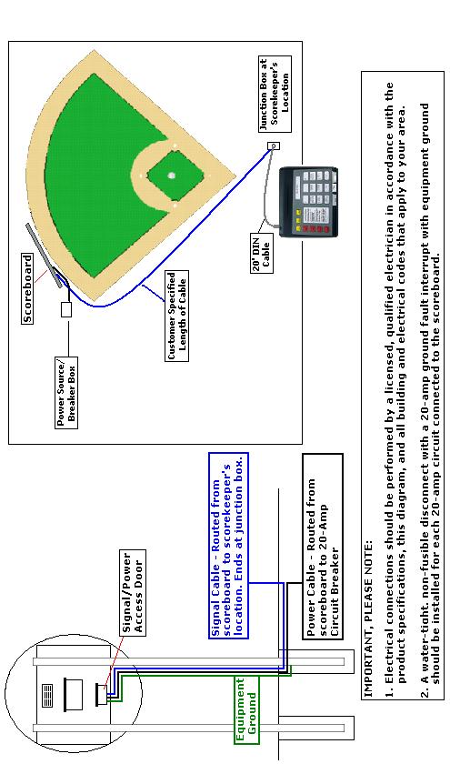
 The control cable must be run in a separate conduit than is used for the electrical service.")

9 RUNNING & CONNECTING THE CONTROL CABLE (For scoreboards with Wireless Remote Control, skip this step.) The control cable must be run in a separate conduit than is used for the electrical service. The control cable should run from the scoreboard to a location that is within 10 feet of the scorekeeper s location and into a 2 X4 wall box. At the scorekeeper s location: Before connecting any cables to the hand held controller make sure that the batteries have been removed. 1. With the communication cable installed between the scoreboard and the 2 X4 wall box, locate the wall plate provided with your installation hardware. 9
10 2. The back of the wall plate has a label indicating how the connections are to be made. As follows connect the black wire on the wall plate to the orange wire, connect the gray wire on the wall plate to the bare (shield) wire in the cable, connect the green wire on the wall plate to the blue wire of the cable, connect the white wire of the wall plate to the white with a blue stripe of the cable. This is for a hand held controller only to connect the red wire to the white with orange stripe wire of the cable. To prevent confusion it is recommended to have purchased the cable with the scoreboard, other cable may not be suitable for the installation giving false errors or communication problems between the controller and the scoreboard. 3. Secure the junction box cover to the installed junction box. At the scoreboard: 4. Remove the signal/power access door located on the back of panel A. 10
11 5. From the ground, run the control cable through a sealed, water-tight conduit then through a water-tight conduit fitting into the left side of the signal cable/power access door and into the scoreboard. A hole is provided for a conduit connector 6. Inside the scoreboard, connect the control cable leads to the appropriate terminals on the terminal block, according to the label above the terminal block. The connections are as follows connect the orange and bare wire of the cable to the terminal block opposite the black & gray wire connection, connect the blue wire of the cable to the terminal block opposite the green wire connection, connect the white with blue stripe of the cable to the terminal opposite the white wire connection. Do not connect the white with the orange stripe of the cable UNLESS YOU ARE USING A HAND HELD CONTROLLER THIS CONNECTION WILL HAVE TO BE MADE AS FOLLOWS: Connect the white with orange stripe of the cable the terminal opposite the red wire connection. MAKING THIS CONNECTION USING A LARGE CONTROLLER WILL BURN THE CONTROLLER OUT. If you need assistance call


12 NOTE: Refer to the connections that were made at the scorekeeper s location. Make the connections at the scoreboard match the connections at the scorekeeper s location. 7. Re-secure the signal/power access door to the scoreboard. RUNNING & CONNECTING THE ELECTRIC SERVICE NOTE: IT IS RECOMMENDED TO HAVE A LICENSED ELECTRICIAN FOR THIS PORTION. IDEALLY, THE SCOREBOARD WILL BE POWERED FROM A DEDICATED 120-VOLT / 20 AMP CIRCUIT. ADDITIONALLY, SINCE THE SCOREBOARD S POWER SHOULD BE TURNED OFF AFTER EACH USE, THERE SHOULD BE EASY ACCESS TO THE POWER SWITCH OR CIRCUIT BREAKER. IF ACCESS TO THE CIRCUIT BREAKER IS NOT AN OPTION, INSTALL A SWITCH SOMEWHERE THAT IS ACCESSIBLE, EVEN IF UNDER THE SCOREBOARD AT AN ABOVE AVERAGE HEIGHT. 1. The scoreboard has a ½ knock-out on the lower right corner for bringing in the electrical service. It can be enlarged if the conduit size is ¾. This is where the conduit from the power source needs to terminate. 12
13 2. The connections are standard black, white, and green (ground). Replace the cover when complete. 13
14 14
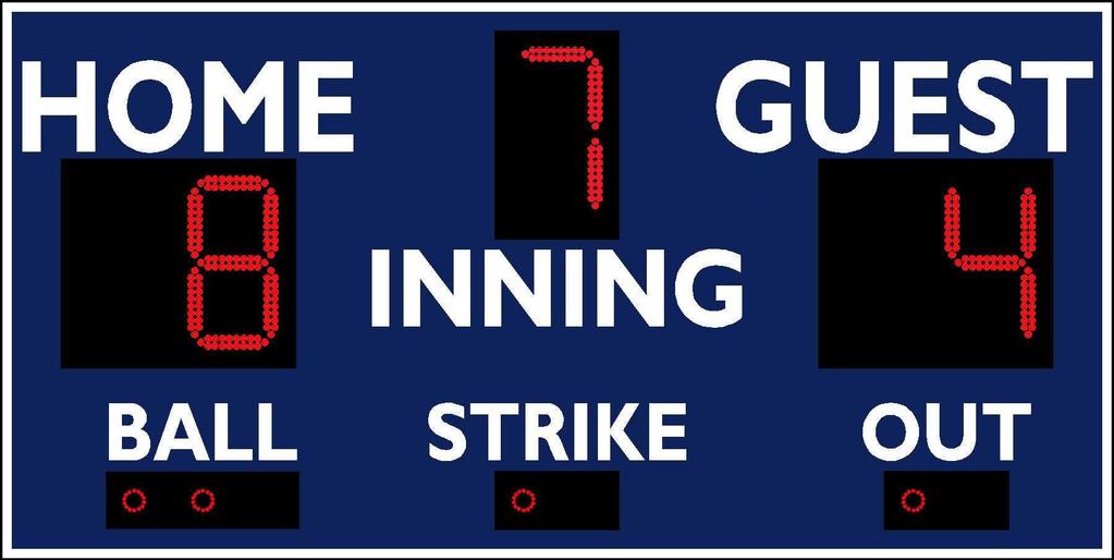
15 TESTING THE INSTALLED SYSTEM Testing the scoreboard system: 1. Turn the power to the scoreboard ON using the power disconnect switch or circuit breaker. The controller has an LED indicator on the top left corner. This indicator should blink any time a key is pressed. If your scoreboard is a cable system, verify that all cable connections are properly terminated and that the 20 supplied cable is properly connected on both the back of the controller and at the junction box. If your scoreboard is a wireless system, verify that the batteries inside the handheld controller have sufficient voltage for operation. There are four (4) AA batteries that supply power to the controller during wireless operation. Together, they should have a minimum of 3.12 Volts in order to operate the controller. 2. The HOME SCORE should display a 5 for about three seconds (indicates baseball mode ), and then both the HOME and GUEST scores should display a 0, while the INNING shows a 1. BALL, STRIKE, and OUT indicators will be blank. If the HOME score does not show a 5 any time the scoreboard is first turned on, follow these steps: Press the SELECT GAME key and hold it for three (3) seconds. Press the INNING Key (#5 key on the keypad). Press the OUT Key (#9 key on the keypad) to store the selection. Press NEW GAME to begin game play. 3. Use the controller keys to verify that all sections of the scoreboard respond properly. Example: Add scores to both teams, increase Innings, Balls, Strikes, and Outs. 4. If the scoreboard displays a flashing 8 in the Inning position, this is either an indication of no signal communication between the scoreboard and controller, or simply an extended period of inactivity with the controller. The timeout period is one hour. If the time is less than that, check all communication cable connections and press NEW GAME on the controller. If the flashing 8 remains, contact Technical Support. NOTE: Always turn both the controller and the scoreboard OFF after each use. If the controller is turned OFF but the scoreboard remains ON, (or if the controller loses communication with the scoreboard), the scoreboard s INNING digit will begin to flash with the rest of the displays blank. This feature is intended to remind the user to turn power to the scoreboard OFF after each use. 15
16 IMPORTANT! Warranty Activation/Installation & Completion Sign Off Sheet NOTE: This sheet must be completely filled out and returned/faxed (270) to Scoreboard Service Company before your warranty can be activated. Your Serial Number Your Model Number Date Purchased Sales Agent Person Authorizing Purchase (title) Date Installation Completed Company or Person Responsible For Installation (address/phone number) This document confirms that the installation for the 4-ft.x 8-ft. Baseball Scoreboard has been completed. All structural, wiring, and power requirements have been met. This unit has been tested in scoring and diagnostic modes, ensuring the functionally of the unit. Scoring/timing equipment responsible party Installer So that we may better serve you, please have this information available in the event you need to call technical support. Customer Service:
MODEL 3312 LED
 INSTALLATION INSTRUCTIONS FOR MODEL 3312 LED www.sportablescoreboards.com 1 Table of Contents DISCRIPTION... 3 THE SCOREBOARD SYSTEM SHOULD INCLUDE THE FOLLOWING PARTS:... 3 INSTRUCTIONS FOR REPORTING
Model 7416LED
 INSTALLATION INSTRUCTIONS FOR Model 7416LED www.sportablescoreboards.com 1 Table of Contents DESCRIPTION... 3 THE SCOREBOARD SYSTEM SHOULD INCLUDE THE FOLLOWING PARTS:... 3 INSTRUCTIONS FOR REPORTING SHIPPING
SC-9
 OPERATING INSTRUCTIONS FOR SC-9 www.sportablescoreboards.com 1 Table of Contents INSTRUCTIONS FOR REPORTING SHIPPING DAMAGE... 3 GETTING STARTED... 6 CABLE SYSTEMS... 6 WIRELESS SYSTEMS... 6 SUPPLYING
SCOREBOARD SPECIFICATIONS FOR
 SCOREBOARD SPECIFICATIONS FOR MODEL 3365-58 LED www.sportablescoreboards.com Sportable Scoreboard Inc. 106 Max Hurt Drive Murray, KY 42071 Phone: 800-323-7745 Fax: 270-759-4112 www.sportablescoreboards.com
OPERATING INSTRUCTIONS FOR MODEL ST-15 5-DIGIT SPORTS TIMER
 OPERATING INSTRUCTIONS FOR MODEL ST-15 5-DIGIT SPORTS TIMER Table of Contents OPERATING INSTRUCTIONS... 0 MODEL ST-15... 0 2- YEAR WARRANTY... 2 IMPORTANT!... 3 Warranty Activation/Installation & Completion
MODEL 9266 LITTLE LEAGUE BASEBALL SCOREBOARD. Instruction Manual
 UNITEC MANUFACTURING DIVISION MODEL 9266 LITTLE LEAGUE BASEBALL SCOREBOARD (WITH INNING BY INNING SCORING & PITCH COUNT) Instruction Manual Mailing Address: PO Box 260, Yorkville, NY 13495-0260 Plant Address:
EVERSAN. Instruction Manual MODEL 9007/9008 TENNIS SCOREBOARD. Address: 34 Main Street, Whitesboro, NY 13492
 MODEL 9007/9008 TENNIS SCOREBOARD Instruction Manual Address: 34 Main Street, Whitesboro, NY 13492 Phone: 315-736-3967 Toll Free: 800-383-6060 Fax: 315-736-4058 SCOREBOARDS TIMERS MESSAGE SIGNS VIDEO DISPLAYS
OPERATING INSTRUCTIONS AND SERVICE MANUAL BASEBALL SCOREBOARD MODEL MP-3350 WITH MP-2002 CONTROL
 OPERATING INSTRUCTIONS AND SERVICE MANUAL BASEBALL SCOREBOARD MODEL MP-3350 WITH MP-2002 CONTROL EFFECTIVE S.N. XXXX JAN 1, 1993 1 1. General Information TABLE OF CONTENTS 1.1 Description 1.2 Identification
EVERSAN. MODEL 9658 EVERSAN PERIOD INDOOR/OUTDOOR MULTI-FUNCTION SCOREBOARD. Instruction Manual
 MODEL 9658 EVERSAN HOME PERIOD POSS. POSS. BONUS BONUS GUEST INDOOR/OUTDOOR MULTI-FUNCTION SCOREBOARD Instruction Manual Address: 34 Main Street, Whitesboro, NY 13492 Phone: 315-736-3967 Toll Free: 800-383-6060
Operating Instructions & Service Manual FOULS
 FOULS Operating Instructions & Service Manual FOULS Basketball Player Fouls Panels Model MP-5215 EFFECTIVE S.N. 17,100, June 18, 2001 TABLE OF CONTENTS PAGE 1. GENERAL INFORMATION 3 1.1 DESCRIPTION 1.2
Basketball Shot Clock Set LX2180 Manual
 Basketball Shot Clock Set LX2180 Manual 72 Industrial Boulevard Wrightsville, GA 31096 Phone: (800) 445-7843 Fax: (800) 864-0212 www.electro-mech.com LX2180 Revision 5 February 8, 2013 Table of Contents
MODEL 9360-SO SOCCER SCOREBOARD
 MODEL 9360-SO SOCCER SCOREBOARD Instruction Manual Address: 34 Main Street, Whitesboro, NY 13492 Phone: 315-736-3967 Toll Free: 800-383-6060 Fax: 315-736-4058 SCOREBOARDS TIMERS MESSAGE SIGNS VIDEO DISPLAYS
OPERATING INSTRUCTIONS AND SERVICE MANUAL 4000 SCOREBOARD CONVERSION. TO PLAY WITH 5000 SCOREBOARD and CONTROL
 OPERATING INSTRUCTIONS AND SERVICE MANUAL 4000 SCOREBOARD CONVERSION TO PLAY WITH 5000 SCOREBOARD and CONTROL EFFECTIVE S.N. 17,500, November 28, 2001 TABLE OF CONTENTS 1. GENERAL INFORMATION 1.1 DESCRIPTION
OPERATING INSTRUCTIONS AND SERVICE MANUAL BASEBALL SCOREBOARD MODEL MP-7388 WITH MP-5000 CONTROL
 OPERATING INSTRUCTIONS AND SERVICE MANUAL BASEBALL SCOREBOARD MODEL MP-7388 WITH MP-5000 CONTROL EFFECTIVE S.N.18,725, July, 2004 TABLE OF CONTENTS 1. General Information 1.1 Description 1.2 Identification
OPERATING INSTRUCTIONS AND SERVICE MANUAL. MODEL MP-3804 BLACK FLAG DISPLAY WITH MP-2002 Control
 OPERATING INSTRUCTIONS AND SERVICE MANUAL MODEL MP-3804 BLACK FLAG DISPLAY WITH MP-2002 Control EFFECTIVE S.N. 18,959 May 2, 2003 TABLE OF CONTENTS 1. General Information 1.1 Description 1.2 Identification
OPERATING INSTRUCTIONS AND SERVICE MANUAL FOOTBALL SCOREBOARD MODEL MP-7442 WITH MP-5000 CONTROL
 OPERATING INSTRUCTIONS AND SERVICE MANUAL FOOTBALL SCOREBOARD MODEL MP-7442 WITH MP-5000 CONTROL EFFECTIVE S.N. 18,725, June, 2005 TABLE OF CONTENTS 1. General Information 1.1 Description 1.2 Identification
SECTION MODEL 2577 INDOOR SCOREBOARD. A. Single-face electronic scoreboard and control console for indoor use.
 SECTION 116643 MODEL 2577 INDOOR SCOREBOARD PART 1 GENERAL 1.01 SECTION INCLUDES A. Single-face electronic scoreboard and control console for indoor use. 1.02 REFERENCES A. Standard for Electric Signs,
OPERATING INSTRUCTIONS AND SERVICE MANUAL OUTDOOR HOCKEY SCOREBOARD MODEL MP-3555 WITH MP-3000 CONTROL MODEL
 OPERATING INSTRUCTIONS AND SERVICE MANUAL OUTDOOR HOCKEY SCOREBOARD MODEL MP-3555 WITH MP-3000 CONTROL MODEL EFFECTIVE S.N.XXXX, DEC 20, 1999 1. General Information TABLE OF CONTENTS 1.1 Description 1.2
Nevco Message Center Installation Manual Retain this manual in your permanent file. 08/27/ Rev. C
 Nevco Message Center Installation Manual Retain this manual in your permanent file. 08/27/2014 135-0144 Rev. C Table of Contents INSTALLATION INSTRUCTIONS... 1 UNPACKING THE EQUIPMENT... 1 MESSAGE CENTER
OPERATING INSTRUCTIONS AND SERVICE MANUAL BASKETBALL SHOTCLOCK MODEL MP-5299
 OPERATING INSTRUCTIONS AND SERVICE MANUAL BASKETBALL SHOTCLOCK MODEL MP-5299 EFFECTIVE S.N. 17,000, December, 2000 TABLE OF CONTENTS 1. General Information 1.1 Description 1.2 Identification 1.3 Damage
ELECTRO-MECH SCOREBOARD CO.
 ELECTRO-MECH SCOREBOARD CO. MP-320 DELAY OF GAME TIMER SCOREBOARD OWNER S HANDBOOK Thank you for choosing an Electro-Mech Scoreboard for your athletic complex. We are confident that your new scoreboard
SECTION MODEL INDOOR SCOREBOARD. A. Four-face electronic scoreboard and control console for indoor use.
 SECTION 116643 MODEL 2650-4 INDOOR SCOREBOARD PART 1 GENERAL 1.01 SECTION INCLUDES A. Four-face electronic scoreboard and control console for indoor use. 1.02 REFERENCES A. Standard for Electric Signs,
ELECTRO-MECH SCOREBOARD CO.
 ELECTRO-MECH SCOREBOARD CO. MODEL 2570 BASKETBALL SCOREBOARD OWNER S HANDBOOK Thank you for choosing an Electro-Mech Scoreboard for your athletic complex. We are confident that your new scoreboard will
OPERATING INSTRUCTIONS AND SERVICE MANUAL HOCKEY SCOREBOARD. MODEL MP-3579 WITH MP-3000 Control
 OPERATING INSTRUCTIONS AND SERVICE MANUAL HOCKEY SCOREBOARD MODEL MP-3579 WITH MP-3000 Control EFFECTIVE S.N. 11370 MARCH 7,1996 TABLE OF CONTENTS 1. General Information 1.1 Description 1.2 Identification
ELECTRO-MECH SCOREBOARD CO.
 ELECTRO-MECH SCOREBOARD CO. MODEL 2350 BASKETBALL SCOREBOARD OWNER S HANDBOOK Thank you for choosing an Electro-Mech Scoreboard for your athletic complex. We are confident that your new scoreboard will
ELECTRO-MECH SCOREBOARD CO.
 ELECTRO-MECH SCOREBOARD CO. MODEL 2150 SHOT TIMER OWNER S HANDBOOK Thank you for choosing an Electro-Mech Scoreboard for your athletic complex. We are confident that your new shot timer will give many
Secured Series: Hub Plus Kit Single Door Controller Package Installation Manual
 Secured Series: Hub Plus Kit Single Door Controller Package Installation Manual This package is designed to simplify the connections to our Secured Series Hub Plus Controller. This will translate into
INSTRUCTION MANUAL DIGI-LOCK. Keyless Entry System. Installation. Programming. Troubleshooting. BASE Industries
 INSTRUCTION MANUAL DIGI-LOCK Keyless Entry System Installation Programming Troubleshooting BASE Industries 45 Pomona Rd. Corona, CA. 9880 Revision F TABLE OF CONTENTS OWNER REGISTRATION CARD INTRODUCTION
ELECTRO-MECH SCOREBOARD CO.
 ELECTRO-MECH SCOREBOARD CO. 3050 FOOTBALL DELAY OF GAME TIMER OWNER S HANDBOOK Thank you for choosing an Electro-Mech Scoreboard Company product for your athletic complex. We are confident that it will
Breaker Panel Technical Practice NPDRP1114
 030-000218 REV E 1114-03E January 30, 2013 Westell Breaker Panel Technical Practice NPDRP1114 FEATURES DIN rail panel accepts up to 6 DIN rail devices (one surge and 5 breakers) Specific configuration
Nevco Outdoor LED Scoreboard Installation Manual
 Nevco Outdoor LED Scoreboard Installation Manual Retain this manual in your permanent file. //5 5-0RA Section : Installation Instructions Installation consists of three steps (Unpacking the Equipment,
ControlKeeper 4. General Information. Connecting Relay Loads. Installation Sheet. Getting Started. Power Supply Wiring. Mounting the Cabinet
 General Information ControlKeeper 4 Installation Sheet Model# CK4-120NO- Model# CK4-277NO The ControlKeeper-4 model is shipped in one package and is configured with either a 120V or a 277V transformer.
EVERSAN. MODEL 9769 BASKETBALL, VOLLEYBALL, WRESTLING SCOREBOARD. Instruction Manual
 MODEL 9769 BASKETBALL, VOLLEYBALL, WRESTLING SCOREBOARD Instruction Manual Address: 34 Main Street, Whitesboro, NY 13492 Phone: 315-736-3967 Toll Free: 800-383-6060 Fax: 315-736-4058 SCOREBOARDS TIMERS
Model LX2550 Product Guide
 Model LX2550 Product Guide Indoor Basketball Scoreboard 72 Industrial Boulevard Wrightsville, GA 31021 Phone:(800) 445-7843 Fax:(800) 864-2012 www.electro-mech.com LX2550 Revision 7 October 21, 2012 Table
Westell. Breaker Panel Technical Practice NPDRP1114
 030-000218 REV F 1114-03F June 29, 2017 Westell Breaker Panel Technical Practice NPDRP1114 FEATURES DIN rail panel accepts up to 6 DIN rail devices (one surge and 5 breakers) Specific configuration of
Model LX2370 Product Guide
 Model LX2370 Product Guide Indoor Basketball Scoreboard 72 Industrial Boulevard Wrightsville, GA 302 Phone:(800) 445-7843 Fax:(800) 864-202 www.electro-mech.com Table of Contents Scoreboard Specifications...3
ELECTRO-MECH SCOREBOARD CO.
 ELECTRO-MECH SCOREBOARD CO. MODEL 8850 HOCKEY SCOREBOARD OWNER S HANDBOOK Thank you for choosing an Electro-Mech Scoreboard for your athletic complex. We are confident that your new scoreboard will give
ELECTRO-MECH SCOREBOARD CO.
 ELECTRO-MECH SCOREBOARD CO. MP-259/220, MP-259/220V, MP-259/220W, MP-269/220, MP-269/220V, MP-269/220W BASKETBALL SCOREBOARDS OWNER S HANDBOOK Thank you for choosing an Electro-Mech Scoreboard for your
VRp Three-Phase Precision AC Voltage Regulator
 VRp-22500-0338 Three-Phase Precision AC Voltage Regulator INSTALLATION INSTRUCTIONS Inspection and Unpacking Please inspect the wooden crate for obvious shipping damage. Some crates contain up to six (6)
Model LX8850 Product Guide
 Model LX8850 Product Guide Indoor Hockey Scoreboard 72 Industrial Boulevard Wrightsville, GA 31021 Phone:(800) 445-7843 Fax:(800) 864-2012 www.electro-mech.com LX8850 Revision 7 February 27, 2013 Table
Model LX8750 Product Guide
 Model LX8750 Product Guide Indoor Hockey Scoreboard 72 Industrial Boulevard Wrightsville, GA 31021 Phone:(800) 445-7843 Fax:(800) 864-2012 www.electro-mech.com LX8750 Revision 7 October 22, 2012 Table
ICS Entrance Management Sign Installation Guide. Version 1.0
 ICS Entrance Management Sign Installation Guide Version 1.0 Thank you for purchasing your new ICS Entrance Management System (EMS) from Innovative Control Systems, Inc. Installation Overview This document
SPECIAL INSTRUCTIONS FOR CAPACITORS COMPACT GENERATORS
 SPECIAL INSTRUCTIONS FOR CAPACITORS COMPACT GENERATORS (WITH CAPACITOR CHARGER BOARD A3517-02) The process depends on Generator and System configuration. This document applies to installation of Capacitors
Model# CKM18 Model# CKM36 Model# CKM48 WARNING
 Installation Instructions Model# CKM18 Model# CKM36 Model# CKM48 WARNING HAZARDOUS VOLTAGES. DISCONNECT FROM SUPPLY BEFORE REMOVING COVERS. NO USER SERVICEABLE PARTS INSIDE. SERVICE BY QUALIFIED PERSONNEL
Installation, Testing, and Operating Procedures 30 AMP PORTABLE AND PERMANENT SERIES GFCI SINGLE and MULTIPHASE
 IMPORTANT! Please read all the information on this sheet. SAVE THESE INSTRUCTIONS! NOTICE BEFORE USING READ INSTRUCTIONS COMPLETELY. TO BE INSTALLED BY A QUALIFIED ELECTRICIAN IN ACCORDANCE WITH NATIONAL
Series 803 LED Product Price Display
 Series 803 LED Product Price Display May 2007 Rev. 1.1 1 Installation and Operation Manual Table of contents 1. Safety.......3 2. Series 803 sign features.......4 2.1 Sign descriptions........4 2.2 Control
Vapor Monitor Interface Module
 Manual No: 577013-951 Revision: A Vapor Monitor Interface Module Installation Guide Notice Veeder-Root makes no warranty of any kind with regard to this publication, including, but not limited to, the
Installation & Operations Manual
 Installation & Operations Manual Emergency Solar Tower Phone 2100-TSL Landline Solar Tower 2100-TSC Cellular Solar Tower 2100-TS9 900 MHz Solar Tower 2100-TST 2-Way Radio Solar Tower 2100-TSV VoIP Solar
It s a Better Way to Weigh!
 Midmark Way Platform Scale It s a Better Way to Weigh! Table of Contents Pre-Installation......................... 2 Specifications... 2 Parts Identification... 3 Assembly & Installation... 3-4 Post Mounted
poly-planar Marine Audio Systems
 ME60BT Bluetooth Amplifier 1 Introduction: The ME60BT is a four channel, 120 Watts RMS Bluetooth wireless audio amplifier, capable of delivering up to 30W RMS per channel. It has a compact, water resistant
TECHKNOW, INC. Kiosk Order Confirmation System INSTALLATION MANUAL. Revision Date: July 11, 2012 Part # Version 3.2
 document Page 1 of 18 TECHKNOW, INC Kiosk Order Confirmation System INSTALLATION MANUAL Revision Date: July 11, 2012 Part # Version 3.2 Techknow, Inc. 393 Mayfield Road Duncan, SC 29334 www.gotechknow.com
HIGH-5 INSTALLATION INSTRUCTIONS /460V Three-Phase Input using ABB ACS355 VFD
 HIGH-5 INSTALLATION INSTRUCTIONS 208-230/460V Three-Phase Input using ABB ACS355 VFD For an electronic copy of these instructions, please visit www./installation-services-and-guides TABLE OF CONTENTS Safety
A note about our online installation instructions:
 A note about our online installation instructions: Most Modern Fan Co. products have been in our assortment for several years or longer. As we continually work to improve product performance and user experience,
QUASAR Installation & Maintenance Guide motorized actuator for windows and skylights
 Functional Fenestration Inc (FFI) Quasar Actuator Application Options On Wall or Frame Awning Skylight Hopper Concealed in Frame or Curtain Wall CAD files available on request from FFI. Optional brackets
sonnen Installation Practical
 sonnen Installation Practical sonnen Components sonnenbatterie eco 8.0 Single Phase System Components 4 sonnenbatterie eco 8.0 Single Phase System Components 5 sonnenbatterie eco 8.0 Single Phase System
Features: Contents: If you are missing any of the above components please contact Racepak at
 -------------------------------------------------------------------------------------------- 250-DS-UDX -------------------------------------------------------------------------------------------- Features:
Overview These instructions are presented as a guideline for installing and setting up the LX Series Breaker Control Panel.
 LX Breaker Control Panels Installation and Setup Procedure Hubbell Building Automation, Inc. 9601 Dessau Road Building One Suite 100 Austin, Texas 78754 512-450-1100 512-450-1215 Fax www.hubbell-automation.com
Installation Instructions. (220V Single-phase Input using ABB ACS550 VFD)
") Installation Instructions (220V Single-phase Input using ABB ACS550 VFD) 1 TABLE OF CONTENTS Parts List.... Page 3 Fan Placement, Spacing, and Clearance..... Page 4 Fan Maintenance.. Page 4 Installation
Installation Instructions (220V Single-phase Input using ABB ACS550 VFD) 1 TABLE OF CONTENTS Parts List.... Page 3 Fan Placement, Spacing, and Clearance..... Page 4 Fan Maintenance.. Page 4 Installation
Installation/Operating Instructions 220V VCB Silhouette/Series E Electric Video Conferencing Background by Draper
 Installation/Operating Instructions 220V VCB Silhouette/Series E Electric Video Conferencing Background by Draper Caution 1 Read instructions through completely before proceeding; keep them for future
Owner s Manual. Models 1503 and 1504 Basic Stand Alone Digital Keypad Entry Devices
 Owner s Manual Models 1503 and 1504 Basic Stand Alone Digital Keypad Entry Devices DoorKing, Inc. 120 Glasgow Avenue Inglewood, California 90301 U.S.A. Phone: 310-645-0023 Fax: 310-641-1586 www.doorking.com
FDS / FDS-R / FDS-PS
 FDS / FDS-R / FDS-PS USER MANUAL For use with 120V 60Hz input. Output is 120V 60Hz at 5amps 600W MAX. switched. ETL LISTED Conforms to UL STD 1241 3091594 79-15167-00 REV. A www.fiberstars.com Page 1 of
Model LX2655 Product Guide
 Model LX2655 Product Guide Indoor Scoreboard for Basketball/Volleyball/Wrestling 72 Industrial Boulevard Wrightsville, GA 31021 Phone:(800) 445-7843 Fax:(800) 864-2012 www.electro-mech.com LX2655 Revision
Blackout Shutter Kits with Breathable Wall Light Traps
 Blackout Shutter Kits with Breathable Wall Light Traps 2018 Growers Supply All Rights Reserved. Reproduction is prohibited without permission. Maintain controlled airflow without sacrificing blackout environments.
INDOOR SPORTS SCOREBOARD INSTALLATION RECOMMENDATIONS REV
 INDOOR SPORTS SCOREBOARD INSTALLATION RECOMMENDATIONS 98-0001-23 REV 1805.03 TABLE OF CONTENTS DISCLAIMER The suggestions and recommendation within this document are intended as a guide for the installation
MODEL 9386 MULTI-SPORT TIMER
 MODEL 9386 MULTI-SPORT TIMER Instruction Manual Address: 34 Main Street, Whitesboro, NY 13492 Phone: 315-736-3967 Toll Free: 800-383-6060 Fax: 315-736-4058 SCOREBOARDS TIMERS MESSAGE SIGNS VIDEO DISPLAYS
FEATURES. AlphaBlueLight Emergency Towers Installation & Operations Manual FIGURE 1: FRONT & REAR VIEWS
 AlphaBlueLight Emergency Towers Installation & Operations Manual FIGURE 1: FRONT & REAR VIEWS FEATURES ADA Compliant (hands free operation) LED call status indicator Powder coated steel construction inside
Site Preparation CHAPTER
 CHAPTER 3 Site Preparation This chapter describes the steps to take and the considerations you should keep in mind prior to installing the modules in an open rack. It also contains information that applies
User Manual. EventCUBE CW/WW
 User Manual EventCUBE CW/WW Introduction: Thank you for your purchase. The EventCUBE CW/WW is a DMX intelligent LED Pin Spot light. This LED Pin Spot light is for the serious production company looking
INSTALLATION INSTRUCTIONS
 LIGHTING CONTROL PANELS 16 AND 24 RELAYS INSTALLATION INSTRUCTIONS INSTALLATION OVERVIEW The installation instructions contained in this document are provided as a guide for proper and reliable installation.
User s Manual. ACS550-PD Stock 3R Irrigation Packaged Drive Supplement to ACS550-U1 User s Manual
 User s Manual ACS550-PD Stock 3R Irrigation Packaged Drive Supplement to ACS550-U1 User s Manual 2 ACS550-PD 3R Irrigation Packaged Drive ACS550 Drive Manuals GENERAL MANUALS ACS550-U1 User s Manual (1
Copy Machine Reader. Installation and Setup Guide
 Copy Machine Reader Installation and Setup Guide CONTENTS 1 COPY MACHINE READER INSTALLATION 1 Overview 1 Reader Specifications 3 CR1120/CR1122 INSTALLATION 3 Copier Interface 3 AC Electrical 3 Communications
Bluetooth Ceiling Fan Control with App Owner's Manual
 READ AND SAVE THESE INSTRUCTIONS 0 Model Number RCBT00 Bluetooth Ceiling Fan Control with App Owner's Manual -Speed Hand Held Transmitter Single Light Supplied with Receiver Includes Light Dimming Selection
CP150B Vandal & Weather Resistant Keypad Security Systems
 Vandal & Weather Resistant Keypad Security Systems EN Security System CP150B - Vandal & Weather Resistant Keypad The CP150B keypad provides alarm and or access control functionality when used on selected
Titan Media Cart. Installation and Operation Manual
 Titan Media Cart Installation and Operation Manual Table of Contents INTRODUCTION SERVICE AND SUPPORT... 1 PRODUCT RETURNS... 1 UNPACKING... 1 TITAN SINGLE MEDIA CART... 2 TITAN DUAL MEDIA CART... 2 BEFORE
FIT. Fuel Island Terminal Installation and Operation Manual. The material in this manual is subject to engineering changes and editorial revisions
 FIT Fuel Island Terminal Installation and Operation Manual The material in this manual is subject to engineering changes and editorial revisions Copyright 2002 OPW Fuel Management Systems OPW Fuel Management
Quick Draw Electronics. Shooting Sports Timer User Manual. Model CLUB All In One
 Quick Draw Electronics Shooting Sports Timer User Manual Model CLUB All In One Rev. C August 2018 QUICKDRAW ELECTRONICS SHOOTING SPORT TIMER SYSTEM THE SYSTEM CONSISTS OF; IMPACT SENSOR LIGHT ASSEMBLY
V8-80HS-1 SERIES OF HIGH-SPEED MOTORIZED ZOOM LENSES
 X684 V8-80HS-1 SERIES OF HIGH-SPEED MOTORIZED ZOOM LENSES Copyright 2000 Vicon Industries Inc. All rights reserved. Product specifications subject to change without notice. Vicon and its logo are registered
Global Water Instrumentation, Inc.
 Instrumentation, Inc. 11390 Amalgam Way Gold River, CA 95670 T: 800-876-1172 Int l: (916) 638-3429, F: (916) 638-3270 Display: EZ100 11/12/04-1 - Congratulations on your purchase of the EZ100 Display.
Quick Start Installation Guide
 apc/l Quick Start Installation Guide Version A2 Document Part Number UM-201 May 2010 OVERVIEW The apc/l is an intelligent access control and alarm monitoring control panel which serves as a basic building
Product Manual MNX10043 REV A MODEL DSB. Dual Sensor Modular Switch box
 Product Manual MNX10043 REV A MODEL DSB Dual Sensor Modular Switch box Contents Section I Overview Introduction..... 2 Description 2 DSB Model Selection.. 2 Section II Installation Mounting Instructions....
Please read these instructions carefully before installing This will ensure an easy start and a great first customer experience with TS4 installation
 Please read these instructions carefully before installing This will ensure an easy start and a great first customer experience with TS4 installation INTERACTIVE INSTALLATION AND SAFETY MANUAL FOR TS4:
COOPER POWER SERIES. RS-485 digital communications accessory board installation and operation instructions. Voltage Regulators MN225074EN
 Voltage Regulators MN225074EN Effective March 2017 Supersedes January 2012 (S225-40-7) RS-485 digital communications accessory board installation and operation instructions COOPER POWER SERIES DISCLAIMER
ClearPass Series CP1000-R
 ClearPass Series CP1000-R Service & Installation Manual Note: Successful turnstile installation depends on reading this manual. Important Note: Please keep this service manual after installation. If an
User s Manual. ACS550-PD 3R Irrigation Packaged Drive Supplement to ACS550-U1 User s Manual
 User s Manual ACS550-PD 3R Irrigation Packaged Drive Supplement to ACS550-U1 User s Manual 2 ACS550-PD 3R Irrigation Packaged Drive ACS550 Drive Manuals GENERAL MANUALS ACS550-U1 User s Manual (1 200 HP)
CRM Control Panel and Weather Detection System CRM3 for DC actuators (part # 40821J) CRM4 for AC actuators (part # 40822K)
 CRM4 for AC actuators (part # 40822K)") CRM Control Panel and Weather Detection System CRM3 for DC actuators (part # 40821J) CRM4 for AC actuators (part # 40822K) CRM Applications CRM includes a control relay box and a power supply; additional
CRM Control Panel and Weather Detection System CRM3 for DC actuators (part # 40821J) CRM4 for AC actuators (part # 40822K) CRM Applications CRM includes a control relay box and a power supply; additional
Specifications for Modular Sound Shadow Sound Masking Sound Management Group, LLC.
 Specifications for Modular Sound Shadow Sound Masking Sound Management Group, LLC. 1.01 General Requirements This section details general requirements for plenum sound masking installations. 1.1 Contract
Manual No: Revision: A. TLS-4XX Consoles. Upgrade Installation Instructions
 Manual No: 577013-961 Revision: A TLS-4XX Consoles Upgrade Installation Instructions Notice Veeder-Root makes no warranty of any kind with regard to this publication, including, but not limited to, the
Part 2: Building the Controller Board
 v3.01, June 2018 1 Part 2: Building the Controller Board Congratulations for making it this far! The controller board uses smaller components than the wing boards, which believe it or not, means that everything
3M Add-On Terminals 4220P (100, 200, 300 & 400 pairs)
") 3M Add-On Terminals 4220P (100, 200, 300 & 400 pairs) Instructions August 2011 3 78-8130-2330-1-C 1.0 General 1.1 The 3M Add-On Terminals 4220P-100, 4220P-200, 4220P-300 and 4220P-400 are designed to expand
3M Add-On Terminals 4220P (100, 200, 300 & 400 pairs) Instructions August 2011 3 78-8130-2330-1-C 1.0 General 1.1 The 3M Add-On Terminals 4220P-100, 4220P-200, 4220P-300 and 4220P-400 are designed to expand
ReachFree ID Installation Instructions for Wash Select II. Unitec
 ReachFree ID Installation Instructions for Wash Select II Unitec www.startwithunitec.com Proprietary Information and Materials of Unitec Inc. Such proprietary information and materials may not be disclosed
Specifications, Installation, and Operating Instructions
 Specifications, Installation, and Operating Instructions Model: Power Vantage AC Panel Protector CAUTION: The installation of a surge protection device () must be done by qualified electrical personnel.
ORB TM 4-20 ma Input Box Installation & Operation Manual
 IOM ORB TM 4-20 ma Input Box Installation & Operation Manual ORB TM 4-20 ma Input Box Installation & Operation Manual CONTENTS I. HANDLING & STORAGE... 1 Inspection and Handling Disposal and Recycling
Alpha Eclipse Pure Color 3600C Series
 3460 Borreson Street San Diego, California 92117 Toll Free: (800) 223-4636 Local: (858) 273-3036 Fax: (888) 923-4636 E-mail: info@alpha-american.com Website: http://alpha-american.com Alpha Eclipse Pure
Type 4 Disconnect Enclosures
 143 SAGINAW CONTROL & ENGINEERING STOCK PRICE LIST Saginaw Control & Engineering s are designed to work in a wide range of environments indoors or outdoors, and will house most standard types of disconnects
D-Pack 6 Classic ORDERCODE 50315
 D-Pack 6 Classic ORDERCODE 50315 Congratulations! You have bought a great, innovative product from Showtec. The Showtec D-Pack 6 Classic brings excitement to any venue. Whether you want simple plug-&-play
Telephony Multi-Taps. 9000T-TP Series
 9000T-TP Series The 9000T-TP series 1 GHz twisted-pair power multi-tap taps off part of its input RF and AC, but lets the rest pass through. It divides the tapped-off signal and power into multiple outputs,
ClearPix Screen In Ceiling Casing Installation Manual Slot Version
 Screen Research Rue du Finistere ZAC Erdre Active 44240 La Chapelle sur Erdre, France Tel. +33 (0) 2 40 77 87 89 Fax +33 (0) 2 40 77 86 78 http://www.screenresearch.com info@screenresearch.com ClearPix
GV-EL124S Electric Strike
 GV-EL124S Electric Strike Featured with a built-in door status sensor, the GV-EL124S is a fail-secure electric strike, but it is field convertible from fail secure to fail safe. It can be mounted either
MESACONTRACT i n c o r p o r a t e d
 MESACONTRACT PRICE LIST & ORDERING INFORMATION AUGUST 2007 Terms and Conditions of Sale Credit terms: Terms are net 30 days of shipment, with approved credit. Cash discount of 1% if paid in 10 days. A
xtablet T1600 Vehicle Holder Installation Guide
 This document will step you through setting up the T1600 Vehicle Holder installation and tips for a safe, clean and long lasting installation. Preparing to Mount the Vehicle Holder Warning : Dock mounting