XEV EX48 Superheat Controller
|
|
|
- Nickolas Golden
- 6 years ago
- Views:
Transcription
 Installation and Operations Manual 1.1. General Warning Please read the following safety precautions and warnings before using this manual: CAUTION!")
1 Instruction Sheet PA January 2014 XEV EX48 Superheat Controller XEV EX48 Superheat Controller with ModBus Communication Capability XEV EX48 Driver for Emerson EX4,5,6,7,8 Electronic Stepper Expansion Valves (-40 F to 55 F SST) Installation and Operations Manual 1.1. General Warning Please read the following safety precautions and warnings before using this manual: CAUTION! This manual is part of the product and should be kept near the controller for easy and quick reference. The controller should not be used for purposes different from those described in this manual. It can not be used as a safety device. Check the application limits before proceeding. SAFETY PRECAUTIONS AND WARNINGS! Check that the supply voltage is correct before connecting the controller. Do not expose to water or moisture: use the controller only within the operating limits and avoid sudden temperature changes with high humidity to prevent condensation from forming. Warning! Disconnect all electrical connections before performing any kind of maintenance. Mount the probe where it is not accessible by the end user. The controller must not be opened. In case of failure or faulty operation, send the controller back to Emerson Climate Technologies with a detailed description of the fault. Verify the maximum current that can be applied to each relay (see Section 15, Specifications). Ensure that the wires for probes, loads, and the power supply are separated and far enough from each other, without crossing or intertwining. In case of applications in industrial environments, the use of main filters (our mod. FT1) in parallel with inductive loads could be useful General Description The XEV EX48 superheat controllers are factory pre-programmed to drive the Emerson EX4,5,6,7,8* electronic stepper expansion valves. The controller regulates evaporator superheat (SH) to optimize performance independent of climate or load conditions. The XEV EX48 controllers have also been pre-set to operate with the Emerson PT5, (4 to 20mA) pressure transducer and the ECN-N60, NTC temperature probe. The LAN connection transmits the pressure signal to the other XEVs; this allows the use of only one pressure transducer in multiplexed cabinet applications. The controller can also have two (2) configurable digital inputs, the first one is dry contact d1s and the other one is at high voltage d2s to simplify connections with cooling demand signal. With the integrated display, it is possible to see the superheat (SH) value, the Percentage valve opening, or the probe values; the local keyboard enables the controller to be programmed without any other devices. An RS485 serial link connects the controller to other Emerson monitoring and supervising systems, such as the Einstein E2 with software version 2.84 and above or Xweb. * If EX7 or EX8 Valves are used, change the tep Code in Pr2 parameter setting (see p.8) 2.2 Ordering Code for Individual Controllers Emerson PCN Description Refrigerant XEV EX48 R404A,507,407A, 22,134a, R410A,CO2 Sub Controllers Only XEV EX48 controller XEV electrical connectors Adie Road P.O. Box St. Louis MO USA CUSTOMER SERVICE (314)

2 2.21 Ordering Codes for Complete Kits Emerson PCN Description Refrigerant XEV EX4 KIT XEV EX5 KIT XEV EX6 KIT XEV EX7 KIT XEV EX8 KIT R404A,507,407A,22, 134a, R410A,CO2 Sub R404A,507,407A,22, 134a, R410A,CO2 Sub R404A,507,407A,22, 134a, R410A,CO2 Sub R404A,507,407A,22, 134a, R410A,CO2 Sub R404A,507,407A,22, 134a, R410A,CO2 Sub 3.0 Wiring Connections Note: If the high voltage Digital Input d2s (cooling demand) is not used, then the dry contact d1s must be used for Cooling Demand. When d1s is used some PR2 parameters must be altered from factory default to; i1p set to CL i1f to CCL i2p set op i2f set to rl Complete Kits XEV EX48 controller XEV Electrical connectors EX Valve (4,5,6,7,8) EXV-M60 Valve Cable PT5-18M Pressure Transducer PT4-M60 Transducer cable ECN-N60 Temperature sensor 90-T40F3 24V Transformer, 40VA 60HZ 120/208/240V 2.22 Ordering Codes for Kits Less Valve 4.0 Valve Connections and Configuration Note: For the XEV EX48 Controller, the valve motor parameter has been pre-adjusted to the Emerson EX valve s Bipolar motor. Emerson PCN Description Refrigerant XEV Kit Less Valve R404A,507,407A,22, 134a, R410A, CO2 Sub Kits Less Valve XEV EX48 controller XEV Electrical connectors EXV-M60 Valve Cable PT5-18M Pressure Transducer PT4-M60 Transducer cable ECN-N60 Temperature sensor 90-T40F3 24V Transformer, 40VA 60HZ 120/208/240V The XEV-EX48 Superheat Controller comes pre-set to specifically work with all other Emerson components listed above. The base Controller model is the XEV22D. UL File Number E tep Model Lst (steps*10) ust (steps*10) Table tep Parameter Table CPP (ma*10) CHd (ma*10) Maximum Current Sr (step/ sec) 0 Manual Setting Par Par Par Par Par 1 EX4 EX5 EX A EX A EX A 325 From table 4-1 select the valve through the tep parameter. This way, you can be sure of the correct configuration Regarding connections, use Table 4-2 as a quick reference on the connections for the Emerson EX valves. Connection Numbering Emerson EX 4 Blue 2 Brown 3 Black 1 White Table Wire Valves (Bipolar)

3 5.0 Absolute Maximum Power The XEV EX48 controller is capable of driving EX4,EX5,EX6,EX7,EX8 stepper valves; listed in Table 4-1 are the maximum values of current that the actuator can supply to the stepper wiring. Use Minimum 20VA Class II transformers. 6.2 XEV EX48 LEDS Each LED function is described in Table 6-2: NOTE: After making the connection, switch the XEV controller OFF and ON to make sure that the valve is positioned properly. Download EX Valve Selection Software by going to link below. ECV-Selection_R07.xls 6.0 Front Panel 7.0 USER INTERFACE Figure XEV EX48 Front Panel 6.1 Keys and Functions Table 6-1 shows the keys found on the front Panel of the XEV EX48 and their corresponding functions: 7.1 Read-Only Values 1. Press and release the UP arrow key. 2. The first read-only label is displayed. 3. Slide labels using the UP or DOWN arrow keys. 4. Press the SET key to see the read-only value. To change and view the parameter, press SET. 5. To exit the fast access menu, press and release the SET + UP arrow keys or wait for the device timeout for 3 minutes. Key SET Function To display and to modify the SUPERHEAT set point. In programming mode, it selects a parameter or confirms a value. By pressing and releasing this key, you will display the Temperature and Pressure values. In programming mode, it scrolls through the parameters and/or increases their values. In programming mode, it scrolls through the parameters and/or decreases their values. Key Combinations To lock and unlock the keyboard. To enter programming mode. 7.2 Superheat Setpoint 1. Press the SET key until the setpoint is displayed. 2. To return and view the temperature, wait for 5 seconds or press the SET key again. 7.3 Modify Superheat Setpoint 1. Press the SET key until the set point is displayed. 2. Use the UP or DOWN arrow keys to change its value. 3. Press SET to store the new value. Table XEV EX48 Front Panel Keys and Functions


4 7.4 Enter Pr1 Parameters List 7.7 How to Assign a MODBUS Address 1. To enter the programming mode, press and hold the SET and DOWN arrow keys together for about 3 seconds or until the dots at the top of the display start flashing. 2. Arrow down to PR2 and press SET to select. 3. PAS for password will display and flash. 4. Use the arrow keys to set the 321 password. Press SET to save. 1. Press the SET + DOWN arrow keys for about 3 seconds. 2. The device will display the first parameter in Pr1 menu. Only 3 parameters to set on Pr1 are Fty, ope, SFd Fty = Type of Refrigerant ope = Start Opening Percentage SFd = Start Function Duration Note: If a time-out occurs while setting the password (PR2 flashes), press SET to resume entering the password 5. Use the arrow keys to scroll through and locate Nod. Press SET. Use the arrow keys to scroll through and locate Std. Press SET. 6. Use the arrow keys to scroll through and locate Adr Press SET. Use the arrow keys to choose the address number of the device. Press SET to save. 7. To exit, press the SET and UP arrow keys together or wait 15 seconds without pressing a key. 7.5 Enter Pr2 Parameters List 1. Enter the Pr1 level menu. 2. Select Pr2 parameter and press SET. 3. The PAS label will be displayed followed by a blinking Insert 321 password using the UP and DOWN arrow keys. 7.6 Modify the Parameters Value 1. Enter the programming mode by pressing the SET and DOWN arrow keys for about 3 seconds. 2. Select the required parameter. 3. Press the SET key to display its value. 4. Use the UP or DOWN arrow keys to change its value. 5. Press the SET key to store the new value and move to the next parameter. 6. To exit, press SET + UP or wait 30 seconds without pressing a key. Note: The set value is stored even when the time-out expires and ends the procedure.
5 8.0 Parameters Note: All pressure parameters are relatives or absolutes depending on the PrM parameter.
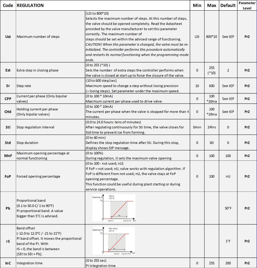
6 8.0 Parameters
7 8.0 Parameters
8 8.0 Parameters

9 8.0 Parameters 9.0 Digital Inputs The XEV EX48 comes with two (2) digital inputs: a voltage-free input and a high voltage input; Both can be configured as cooling call. In this way the cooling signal can come from the controllers with direct load outputs or via the Controllers with voltage-free outputs. One of these inputs must be configured as the cooling call Forced Opening 11.1 Probes The recommended temperature probe placement is illustrated in Figure For Suction Lines less tan 7/8 Diameter, bulb placement should be at 12 o clock position. For Suction lines greater tan 7/8 Dia. The preferred bulb placement is at 4 or 8 o clock For suction pressure probes, there is no particular recommendation. Temperature Sensor Must Be insulated If necessary, change the FoP parameter to force the valve to open. For example, if FoP is set to 50 (FoP = 50), the valve will be opened at half of full scale. To disable this function, set the FoP to default value (FoP = not used). The valve opening is enabled only when CCL digital input is enabled Electrical Connections The controller comes with a screw terminal Block to connect cables with a cross section up to 2.5 mm 2. Heat-resistant cables have to be used. Before connecting the cables, verify that the power supply complies with the controller s requirements. Separate the probe cables from the power supply cables, from the outputs and the power connections. Do not exceed the maximum current allowed on each relay, in case of heavier loads, use a suitable external relay. Figure Recommended Temperature Probe Placement
10 12.0 RS485 Serial Line 14.0 Display Messages All models can be connected to the monitoring and supervising system XWEB500. If Mod = StD, the standard MODBUS-RTU protocol is used; if Mod = AdU, the custom XWEB library is required. This last configuration makes it possible to use the same serial address of the thermostat that gives the cooling request to XEV. In this way, it is possible to reduce the number of addresses used How to Use the Hot Key 13.1 How to Program a Hot Key From the Controller (Upload) 1. Program one controller using the front keypad. 2. When the controller is ON, insert the Hot Key and press the UP arrow key; the upl message will appear followed by a flashing End LED. 3. Push the SET key and the End LED will stop flashing. 4. Turn OFF the controller, remove the Hot Key, then turn it ON again. Note: The Err message is displayed in case an error or failure in programming occurs. In this case, push the UP arrow key again if you want to restart the upload or remove the Hot Key to abort the operation How to Program the Controller Using a Hot Key (Download) 1. Turn OFF the controller. 2. Insert a programmed Hot Key into the 5-pin connector and then turn the controller ON. 3. Automatically the parameter list of the Hot Key is downloaded into the controller memory, the dol message will blink followed by a flashing End LED. 4. After 10 seconds, the controller will restart work with the new parameters. 5. Remove the Hot Key. Note: The Err message is displayed in case an error or failure in programming occurs. In this case, turn the unit OFF and then ON if you want to restart the download or remove the Hot Key to abort the operation Alarm Recovery Probe alarms P1 and P2 start a few seconds after the fault in the probe; they automatically stop few secondsafter the probe restarts normal operation. Check the connections before replacing the probe. Maximum and minimum alarms HSH, LSH, MoP, and LoP automatically stop as soon as the variable returns to normal values. The controller is provided with an internal check to verify memory integrity. Alarm EE flashes when a failure in the internal memory is detected. In this case, call for service.
11 15.0 Specifications Housing Self extinguishing ABS Case Front: 4 DIN modules, 70 mm x 135 mm with male and female connectors Dimensions Depth: 60 mm Mounting: DIN RAIL mounted in a omega (3) din rail Protection IP20 Connections Detachable screw terminal block 2.5 mm2 wiring Power Supply 24VAC/DC ±10% Power Absorption (depending on the valve) 20VA max Display Three (3) digits with icons, red LEDs, height 14.2 mm Inputs 1 temperature probe Pt1000 or NTC (For EX Valves) Digital Inputs 1 pressure transducer 4 to 20mA (For EX Valves) or 0 to 5V 1 free of voltage 1 at high voltage Outputs for Valve Bipolar or unipolar valves Data Storage On the non-volatile memory (EEPROM) Kind of Action 1B Pollution Grade Normal Software Class A Temperature Operating: 0 to 60 C Relative Humidity 20 to 85% (no condensing) Resolution 0.1 C or 1 F Precision at 25C ±0.7 C ±1 digit 16.0 E2 MODBUS Network Wiring Connect MODBUS Network to the RS485 Connector on the E2 PIB board (Belden 8641 recommended). Note to wire the RS485 +/- polarity at the E2 in the reverse of the XEV devices. Position the three termination jumpers to the UP (terminated) position to provide RS485 termination at the E2. Do not connect the shield of the MODBUS network to the E2 PIB center terminal. Instead, use a 100 ohm 1/2 watt resistor to connect the MODBUS cable shield to earth ground. At each XEV device, wire the MODBUS cable to the RS485 +/- terminals and connect the MODBUS shield to the pin 16 terminal. Terminate the end of the MODBUS network at the last XEV device on the daisy chain with the MODBUS termination block (P/N ), or by connecting a 150 ohm resistor between the MODBUS +/- terminals.


 and configured in E2 General Services ( Serial tab) to enable COM4 or an E2 Expansion COM Card (P/N 637-4871) to enable COM6.")
12 17.0 ECT MODBUS Networking to E2s 17.1 E2 Setup of Devices Set Up Network Ports Before setting up device, the port on the E2 that has the MODBUS cable connected must be set up as a MODBUS port. 1. Log in to the E2 with Level 4 access. 2. Press followed by General Controller Info 3. Press to open the Serial tab of the General Controller Info setup screens: Figure Location of E2 COm Parts (E2 Versions 3.xx and below) Connecting an XEV controller to an E2 requires the E2 to be version 2.84 or above. Contact Retail Solutions for upgrade information if the controller is a version before An E2 has up to three COM ports that can be assigned for MODBUS communication: COM2, an RS485 port on the E2 power interface board, and COM4 and COM6, which are optional ports requiring expansion cards. COM4 is recommended for MODBUS connection of Emerson units. COM ports can only be used for one function; in other words, if COM2 is set up as the I/O network, you cannot connect MODBUS devices to COM2. Ensure your E2 is equipped with an RS485 COM Card (P/N ) and configured in E2 General Services ( Serial tab) to enable COM4 or an E2 Expansion COM Card (P/N ) to enable COM6. Connect the MODBUS network cable to the three terminal connector on the COM port you wish to assign as MODBUS. Reverse polarity of +/- on RS485 cable from E2 to the device. Figure Serial Communications Manager Screen 4. This screen will have a Connection field for all COM ports on the E2. Highlight the COM port connection field that will be used for the device, and press LOOK UP. From the list of network types, select MODBUS. 5. Four fields will become visible underneath the COM port connection field, which pertain to the way the device communicates: Baud - Default setting is 19.2k. The baud rate setting should be set to match the baud rate of the device(9600). (All devices connected to the same COM port should be set to the same baud rate.) Data Size - Leave this field at the default value (8) Parity - Leave this field at the default value(none) Stop Bits - Leave this field at the default value (1). 6. Press to save changes and exit Add and Connect the Device To enable communications between E2 and the units, the devices must be added and addressed in E2. 1. Log in to the E2 with Level 4 access. 2. Press - Connected I/O Boards and Controllers. Figure MODBUS Networking Figure Num Network Ctrls NetSetup Screen
.")

13 3. In the Num Network Ctrls: NetSetup screen, under the ECT tab, enter the number of devices in the Quantity field. (Max shows the maximum number of devices allowed on the network.) 4. Press to return to the Network Setup menu, then select - Network Summary. 5. Locate the units you added to the network list (press and to scroll through the list). If desired, enter new name for each device in the Name field. Unknown - The device is not communicating or has not been commissioned. Verify the device is powered up, wired correctly, and has the proper network address, baud rate, and parity. No Port - No port is set up in the E2 Serial Configuration Manager to be a MODBUS port. Wrong FW Rev - This message is likely caused by the device having a firmware version older than the minimum revision required by E2 for communication. Replace the device with a new one or a device that has the latest version of firmware on it. Figure Network Summary Screen 6. By default, each device in the network list has a board number of 0. To set the address and begin communication, choose the device and press. In the list of MODBUS devices, choose the address number corresponding to the address set up through the front display, and press to select it. A window will open where you can specify the address of the controller. If a network ID has already been selected, its name will be shown next to the network ID in this list. If the network ID you are trying to assign has already been used, you must set the address on this device to a different number that is not being used. Figure Network Summary Screen 17.2 Wiring Types Retail Solutions specifies Belden #8761 shielded twisted pair cables for use as MODBUS wiring (or Belden #82761 and Belden #88761 for plenum installations). For MODBUS network wiring of XEV series of controllers to E2, Belden #8641 (CPC P/N ) is the recommended wire type to use. If the recommended cable is not available in your area, be sure the wiring meets or exceeds the following Figure List of MODBUS Devices 7. Repeat Steps 5 and 6 until each device has a name and address. 8. When finished, press to return to the Network set up menu, then press Network Summary (Figure 17-7). Locate the devices you set up, and look at each device s status in the Status field You will see one of the following messages: Online - The device is communicating normally. Offline - The device is not communicating, has not been commissioned, is not functional, or is not powered up. Verify the device is powered up, wired correctly, and has the proper network address, baud rate, and parity.
14 17.3 MODBUS Termination Box Because the XEV device has no on-board means of termination, use the MODBUS termination block (P/N ) for termination that can be wired to the end of the cable segment using the three pin connector. Wire the two signal wires to the outside terminals, and connect the shield to pin 16, keeping the exposed shield wire length as short as possible (3 inches ideal maximum length). Figure MODBUS Termination Block (P/N ) EmersonClimate.com/FlowControls Technical Support: PA R1 (01/14) Emerson is a trademark of Emerson Electric Co Emerson Climate Technologies, Inc. All rights reserved.
EXD-TEVI Economizer Controller for Tandem Compressors
 Technical Bulletin EXD-TEVI is a stand-alone controller for enhanced wet vapor injection for Copeland tandem Scroll compressors in heating applications. Features EXD-TEVI Emerson solution for specified
Controllers for compressor racks with advanced energy saving. PN08 September 2016
 page 1 / 16 XC400/600 for small/medium compressor rack management Dixell introduces the new compact parametric controllers for compressor rack with. Dixell presents the XC400/600 series, dedicated to the
COMPUTER PROCESS CONTROLS
 TECHNICAL BULLETIN Installation Instructions: ESR8 Valve Regulator (P/N 810-3195) Introduction The ESR8 Valve Regulator board (P/N 810-3195), shown in Figure 1, is a Lon- Works Echelon based electronic
Control Techniques Variable-Speed Drive (VSD) Interface to E2 v and Above
 Interface to E2 v and Above") TECHNICAL BULLETIN Part #: 026-4122 Revision 0 Date: 2/5/2007 Control Techniques Variable-Speed Drive (VSD) Interface to E2 v. 2.40 and Overview Beginning with version 2.40, the E2 RX, BX, and CX series
TECHNICAL BULLETIN Part #: 026-4122 Revision 0 Date: 2/5/2007 Control Techniques Variable-Speed Drive (VSD) Interface to E2 v. 2.40 and Overview Beginning with version 2.40, the E2 RX, BX, and CX series
MODEL: R1M-P4. PC Recorders R1M Series. SPECIFICATIONS OF OPTION: Q COATING (For the detail, refer to M-System's web site.)
") PC Recorders Series PC RECORDER (4 totalized counter inputs, 8 contact inputs and outputs) Functions & Features Industrial recorder on PC Totalized counter inputs Counts stored in E 2 PROM Easy system
PC Recorders Series PC RECORDER (4 totalized counter inputs, 8 contact inputs and outputs) Functions & Features Industrial recorder on PC Totalized counter inputs Counts stored in E 2 PROM Easy system
UNIT CONTROLLER 7 (UC7) Operation & Installation. Hydronic Units
 Operation & Installation. Hydronic Units") UNIT CONTROLLER 7 (UC7) Operation & Installation Hydronic Units Date: 1 November 2012 Issue: 5 Page 1 of 17 Contents 1. Connections, hydronic unit... 3 2. Functions assigned to SSR1, SSR2 and AUX... 3
UNIT CONTROLLER 7 (UC7) Operation & Installation Hydronic Units Date: 1 November 2012 Issue: 5 Page 1 of 17 Contents 1. Connections, hydronic unit... 3 2. Functions assigned to SSR1, SSR2 and AUX... 3
AE R6 August CoreSense Protection for Copeland Discus Compressors
 August 2018 CoreSense Protection for Copeland Discus Compressors TABLE OF CONTENTS SAFETY... 3 Safety Instructions... 3 Safety Icon Explanation... 3 Instructions Pertaining to Risk of Electrical Shock,
Extruder Controls ExtruVision S
 Extruder Controls ExtruVision S ExtruVision S - The compact system solution for controlling, visualization, and operating extrusion systems Combination of control panel BA Touch with 5.7'' monitor and
AE R6 July 2018 Electronic Unit Controller
 July 2018 Electronic Unit Controller TABLE OF CONTENTS Safety... 3 Safety Instructions... 3 Safety Icon Explanation... 3 Instructions Pertaining to Risk of Electrical Shock, Fire, or Injury to Persons...
rcc.1081 Installation Instructions
 rcc.1081 Installation Instructions Table of Contents Introduction...1 Specifications...2 Mounting...3 Wiring...5 Wiring Method...7 BACnet Network Wiring...8 Setting BACnet Address...9 Setting the BACnet
Supplementary operating instructions for your air curtain system Controller TMC 500
 Supplementary operating instructions for your air curtain system Controller TMC 500 (Translation of the original) Serial number: Year: Please quote this number when contacting customer service! Date 08.04.2016
ETM MD100 Drive System 1/2HP (370W) User Manual. Table of Contents. Drive Features
 User Manual. Table of Contents. Drive Features") Table of Contents Drive Features... 1 Drive Specifications... 2 Certifications... 3 Installation - Drive Dimensions... 3 Motor Dimensions (mm)... 4 Drive Mounting... 4 Wiring... 5 I/O Terminals... 9 Menu...
Table of Contents Drive Features... 1 Drive Specifications... 2 Certifications... 3 Installation - Drive Dimensions... 3 Motor Dimensions (mm)... 4 Drive Mounting... 4 Wiring... 5 I/O Terminals... 9 Menu...
Rev 2 08-OCT Control Link ACC Anti-Condensate Controller System Installation and Operation Manual
 026-4704 Rev 2 08-OCT-2010 Control Link ACC Anti-Condensate Controller System Installation and Operation Manual 3240 Town Point Drive NW Suite 100 Kennesaw, GA 30144 Phone: 770-425-2724 Fax: 770-425-9319
Rack Input Module Installation Instructions
 Rack Input Module Installation Instructions DOC. #560105000 A 7/30/04 PRINTED IN U.S.A. Regulatory Compliance Safety This device has been tested and found to be in compliance with the requirements set
Millennium Simplicity Elite Parameter Points and Quirks
 Millennium Simplicity Elite Parameter Points and Quirks How to access, view and change parameter settings Program Button Test Reset UP Alarms Change Data Address Down 1. Push the Program button once. The
Type EKE 1B. English. More info. Applications. 1. Superheat controller: standalone / network. 2. Valve driver. Dimensions in mm EKE 1B
 ENGINEERING TOMORROW 080R9321 Installation guide Electronic superheat controller Type EKE 1B Introduction Superheat controller EKE 1B is for use where superheat must be accurately controlled, typically
Rev CH Breaker Gateway Installation and Operation Manual
 026-1710 Rev 1 05-15-07 CH Breaker Gateway Installation and Operation Manual 1640 Airport Road, Suite 104 Kennesaw, GA 31044 Phone: (770) 425-2724 Fax: (770) 425-9319 ALL RIGHTS RESERVED. The information
Soft Starter Remote Operator. Section 1.0 Introduction 1.1 Important user information General Manual description...2.
 Section 1.0 Introduction 1.1 Important user information... 2 1.2 General... 2 1.3 Manual description...2 Contents Section 2.0 Specification 2.1 General technical data...3 2.2 Dimensions...3 Section 3.0
Carbon Monoxide Sensor - ModBus
 Introduction The CO Sensor uses an electrochemical sensor to monitor CO level in a range of 0 to 500 ppm and communicates via an RS-485 network configured for ModBus protocol. Before Installation Read
quick start guide Carel EVD Evolution MODBUS Device E2 Setup for
 Carel EVD Evolution MODBUS Device E2 Setup for 527-0355 This document will guide you through setting up and commissioning the Carel EVD Evolution MODBUS device in the E2 controller. Note that Open MODBUS
4-step Chiller and Heat Pump Controller
 4-step Chiller and Heat Pump Controller Technical Data Sheet GENERAL DESCRIPTION MODELS CODE MODEL DESCRIPTION MW324000 ECH 420 HEAT PUMP WITH 4 STEPS/ 2 CIRCUITS + MODBUS MW324005 ECH 420/V WITH SCREW
MODEL: R1M-D1. PC Recorders R1M Series. SPECIFICATIONS OF OPTION: Q COATING (For the detail, refer to M-System's web site.)
") PC Recorders R1M Series PC RECORDER (contact output, 32 points) Functions & Features Industrial recorder on PC 32-point open collector outputs Easy system expansion via Modbus RTU Recorded data exportable
PC Recorders R1M Series PC RECORDER (contact output, 32 points) Functions & Features Industrial recorder on PC 32-point open collector outputs Easy system expansion via Modbus RTU Recorded data exportable
MCX08M2 Programmable controller
 Data sheet MCX08M2 Programmable controller MCX08M2 is an electronic controller that holds all the typical functionalities of MCX controllers in the compact size of 8 DIN modules: programmability connection
User s manual. Programmable panel meter IPD
 User s manual Programmable panel meter IPD Assembly Wall assembly: +0,5 +0,2 Window of 46 x 91 mm (2.5" x 3.5" ) Made with ABS (UL94-HB) -0-0 General cares in the installation The equipments must not be
INSTALLATION MANUAL. LC 200 Electronic Overload Guard. Software versione PW0501 R 0.3
 INSTALLATION MANUAL LC 200 Electronic Overload Guard Software versione PW0501 R 0.3 CONTENTS MAIN FEATURES LC 200 TECHNICAL FEATURES Page 2 SYMBOLS Page 3 WARNINGS Page 3 IDENTIFICATION DATA PLATE Page
Technical data. Safety notes. Product features
 Technical data sheet BKN230-MOD 11-00002.F Communication and power supply unit for motorised fire dampers Communication via RTU (RS-48) AC 230 V supply via Euro plug Power is supplied to the actuators
INSTALLATION INSTRUCTIONS
 www.altroniccontrols.com INSTALLATION INSTRUCTIONS EXACTA 21 MONITORING AND CONTROL SYSTEM CAUTION: The EXACTA 21 CONTROL SYSTEM is CSA CERTIFIED FOR use in Class I, GROUPS C & D, Division 2 hazardous
XR-CHC and XRB-CHC Refrigeration controllers with Bluetooth connectivity
 XR-CHC and XRB-CHC Refrigeration controllers with Bluetooth connectivity PN 13/18 September Dixell introduces its new XR-CHC and XRB-CHC controllers with Bluetooth connectivity for refrigerated applications.
EE360. High-End Moisture in Oil Transmitter. Typical applications. Features EE360 EE360. (+34)
") is dedicated for reliable monitoring of lubrication, hydraulic and insulation oils as well as diesel fuel. In addition to highly accurate measurement of water activity (a w ) and temperature (T), calculates
is dedicated for reliable monitoring of lubrication, hydraulic and insulation oils as well as diesel fuel. In addition to highly accurate measurement of water activity (a w ) and temperature (T), calculates
IntesisBox. v.0.1. User Manual Issue Date: 12/2017 r1.3 EN
 IntesisBox HS-RC-MBS-1 v.0.1 Modbus RTU (EIA-485) Interface for Hisense air conditioners. Compatible with commercial line of air conditioners commercialized by Hisense. User Manual Issue Date: 12/2017
Quick Start Installation Guide
 apc/l Quick Start Installation Guide Version A2 Document Part Number UM-201 May 2010 OVERVIEW The apc/l is an intelligent access control and alarm monitoring control panel which serves as a basic building
XC1000D SERIES: CONTROLLERS FOR APPLICATIONS UP TO
 D: 10 DIN Rail 82x156mm XC1000D SERIES: CONTROLLERS FOR APPLICATIONS UP TO 15 COMPRESSOR/FAN OUTPUTS SERIAL OUTPUT XC1000D series for comsors and condensing fans monitoring and management of medium-large
H704-42(H)(E), H704-42/1(H)(E)
(E), H704-42/1(H)(E)") POWER MONITORING INSTALLATION GUIDE H704-42(H)(E), H704-42/1(H)(E) Branch Current Monitor DANGER NOTICE Installer's Specifications General: Operating Temp. Range 0 to 60 C (32 to 140 F) (
POWER MONITORING INSTALLATION GUIDE H704-42(H)(E), H704-42/1(H)(E) Branch Current Monitor DANGER NOTICE Installer's Specifications General: Operating Temp. Range 0 to 60 C (32 to 140 F) (
MAKING MODERN LIVING POSSIBLE AK-255 CO 2. Controller On-Site Installation Guide DANFOSS ELECTRONIC CONTROLS & SENSORS
 MAKING MODERN LIVING POSSIBLE Controller On-Site Installation Guide DANFOSS ELECTRONIC CONTROLS & SENSORS How to Use This Guide Read this Guide completely as you install and start up your new Controller.
UNIVERSAL CURRENT CONVERTER
 UNIVERSAL CURRENT / VOLTAGE CONVERTER AC/DC Current / Voltage Analyzer The is the first CURRENT / VOLTAGE CONVERTER & ANALYZER ALL IN ONE - of the market. It allow you to connect all isolated current sensors.
2 Table of Contents 1. TABLE OF CONTENTS. 1. Table of Contents Introduction Wiring Diagram Terminals Review...
 TPR-6 Temperature Protection Relay Instruction Manual Ver. June 1 st 2010 2 Table of Contents 1. TABLE OF CONTENTS 1. Table of Contents... 2 2. Introduction... 3 3. Wiring Diagram... 5 4. Terminals Review...
MODEL: R1M-GH. PC Recorders R1M Series
 PC Recorders Series PC RECORDER (thermocouple or DC input, 16 points) Functions & Features Industrial recorder on PC 16-point thermocouple or DC inputs Easy system expansion via Modbus RTU Recorded data
RTD-W Installation Instructions
 RTD-W Installation Instructions 0V +V POWER 15-24VDC 0V S1 S2 S3 0V S4 S5 S6 English RTD-W Installation Instructions 100.00 RTD-W Control Interface realtime Control Systems 24VAC/30VDC, 1A REMC P1 P2 RS485
MODEL: R1M-A1. PC Recorders R1M Series. SPECIFICATIONS OF OPTION: Q COATING (For the detail, refer to M-System's web site.)
") PC Recorders R1M Series PC RECORDER (contact input, 32 points) Functions & Features Industrial recorder on PC 32-point dry contact inputs Easy system expansion via Modbus RTU Recorded data exportable to
PC Recorders R1M Series PC RECORDER (contact input, 32 points) Functions & Features Industrial recorder on PC 32-point dry contact inputs Easy system expansion via Modbus RTU Recorded data exportable to
Thermoelectric Cooler Controller TED1000
 Thermoelectric Cooler Controller TED1000 Operating Instructions MANUAL-TED1000-1.0 Aug 2015 Rev.1 2 Contents 1 General... 4 1.1 Warranty and Assistance... 4 1.2 Maintenance... 4 1.3 General Safety Considerations...
MX200 SERIES Modbus Card 50P GE Zenith Controls. Operation and Maintenance Manual 50R-2200B 12/00
 g MX200 SERIES Modbus Card 50P-1105 GE Zenith Controls 50R-2200B 12/00 Operation and Maintenance Manual Table of Contents Overview...01 Page LED Indicator...02 Installation...03 Installing the Network
FAN SPEED CONTROLLERS
 SETION INDEX FUNTIONS XV100 - SINGLE-PHASE FAN SPEED MANAGEMENT Single-phase speed controllers XV300 - THREE-PHASE FAN SPEED MANAGEMENT SERIAL OUTPUT Three-phase inverter speed controllers and programming
UNT1100 Series. Binary Output Jumpers AO2 AO1 AO3 AO4 AOCM AOCM AOCM AOCM AO1. AI Switches Job Information N2 Address. Ref N2+ N2- ADDR 0 = ALL OPEN
 1 2 8 4 AI6 R R Installation Bulletin UNT1100 Issue Date 0309 UNT1100 Series Introduction The Unitary (UNT) controller (UNT1100 Series) is a digital controller with applications for air handling units,
USER S MANUAL. DAS-G01 The Power of Tomorrow
 USER S MANUAL DAS-G01 The Power of Tomorrow Richmond Heights 2018 0 USER S MANUAL DAS-G01 The Power of Tomorrow Richmond Heights 2018 Page 1 USER'S MANUAL TABLE OF CONTENTS Page # 1.0 GENERAL INFORMATION...
XB800D Series (v.1.0)
") XB800D Series (v.1.0) INDEX 1. IMPORTANT RECOMMENDATIONS 3 1.1 PRODUCT DISPOSAL (WEEE) 4 2. INTRODUCTION 5 3. GENERAL SPECIFICATIONS 5 3.1 PROCESSING ENVIRONMENT 5 3.1.1 Fields of application... 5 3.1.2
XB800D Series (v.1.0) INDEX 1. IMPORTANT RECOMMENDATIONS 3 1.1 PRODUCT DISPOSAL (WEEE) 4 2. INTRODUCTION 5 3. GENERAL SPECIFICATIONS 5 3.1 PROCESSING ENVIRONMENT 5 3.1.1 Fields of application... 5 3.1.2
CDD Carbon Dioxide Transmitter
 Introduction The OSA CO2 transmitter uses Infrared Technology to monitor CO2 levels within a range of 0 2000 ppm and outputs a linear 4-20 ma or 0-5/0-10 Vdc signal. The enclosure is designed to operate
TECHNICAL REFERENCE MANUAL FOR CAREL CONTROLLERS
 TECHNICAL REFERENCE MANUAL FOR CONTROLLERS IOM-02 April 2017 Contents Page FUNCTIONAL LAYOUT... 1 pco5+ DESIGN... 2 SERIAL PORTS... 3 MOUNTING, DIMENSIONS & INSTALLATION... 4 Installation... 5 Environmental
MOD-RI Room Interface Modules with Modbus
 Product sheet MOD3.00 Type MOD-RI MOD-RI Room Interface Modules with Modbus The MOD-RI are room interface modules designed to provide room control interface for the building management systems. The MOD-RI
Rev 3 06-APR Modular Refrigerant Leak Detection Sensor (MRLDS) Installation and Operation Manual
 Installation and Operation Manual") 026-1307 Rev 3 06-APR-2010 Modular Refrigerant Leak Detection Sensor (MRLDS) Installation and Operation Manual 3240 Town Point Drive NW Suite 100 Kennesaw, GA 30144, USA Phone 770-425-2724 Fax 770-425-9319
026-1307 Rev 3 06-APR-2010 Modular Refrigerant Leak Detection Sensor (MRLDS) Installation and Operation Manual 3240 Town Point Drive NW Suite 100 Kennesaw, GA 30144, USA Phone 770-425-2724 Fax 770-425-9319
isma-b-fcu FCU Hardware User Manual Global Control 5 Sp. z o.o. Warsaw, Poland
 isma-b-fcu User Manual FCU Hardware Global Control 5 Sp. z o.o. Warsaw, Poland www.gc5.pl Table of contents 1 Introduction 3 1.1 Document change log 3 1.2 Safety rules 3 1.3 Technical specifications 4
AIR CONDITIONING CATALOGUE
 AIR CONDITIONING CATALOGUE INDEX THE COMPANY APPLICATIONS PLUS PRODUCTS 1 CIRCUIT UP TO 2 COMPRESSOR CONTROLLERS IC100 advanced multifunction controllers 2 CIRCUIT UP TO 6 COMPRESSOR CONTROLLERS IC200
Product Manual SZ2141
 Product Manual SZ11 Refrigeration Controller Communicating Controls Description The SZ11 is a microprocessor-based refrigeration controller and alarm interface designed to control three coolers or freezers
MODEL: R2K-1 SEN TRONIC AG. R2K Series
 1 MODEL: R2K-1 R2K Series /RS-485 CONVERTER Functions & Features Bidirectional converter between and RS-485 used when connecting Modbus RS-485 devices to a PC CE marking Standard: Conforms to, EIA Transmission
DUCM Hardware. Niobrara Research & Development Corporation P.O. Box 3418 Joplin, MO USA
 DUCM Hardware Manual DUCM Hardware Installation Manual This manual covers the DUCM hardware features and installation procedures. Effective: May 29, 2015 Niobrara Research & Development Corporation P.O.
UDC 1000 and UDC 1500 MICRO-PRO SERIES UNIVERSAL DIGITAL CONTROLLERS
 UDC 1000 and UDC 1500 MICRO-PRO SERIES UNIVERSAL DIGITAL CONTROLLERS EN0I-6041 12/99 PRODUCT SPECIFICATION SHEET OVERVIEW The UDC 1000 and UDC 1500 are microprocessor-based 1/16 DIN and 1/8 DIN controllers
Ethernet / RS485 Gateway
 Ethernet / RS485 Gateway CONFIGURATION HANDBOOK ICL70 LOREME 12, rue des Potiers d'etain Actipole BORNY - B.P. 35014-57071 METZ CEDEX 3 Phone 03.87.76.32.51 Contact : Commercial@Loreme.fr - Technique@Loreme.fr
mark150s mark150/485s DDC controllers Summary
 mark150s mark150/485s DDC controllers Summary DDC (Direct digital control) controller mark150s and mark150/485s are free programmable process stations with ARM Cortex M4 processor and OS FreeRTOS. They
INSTALLATION INSTRUCTIONS MBPEFY Series Mixing Box for Mitsubishi PEFY Series Units. Before Starting Installation Warning. Installation Instructions
 Before Starting Installation Warning Shut power to unit prior to any work being done. Personal injury or death could result. Only qualified HVAC service personnel should install, troubleshoot, repair or
XT-9100 Technical Bulletin
 System 9100 Technical Manual 636.4 Technical Bulletins Section Technical Bulletin Issue Date 0896 XT-9100 Technical Bulletin XT-9100 Extension Module/XP-910x Expansion Modules Page 3 Introduction 3 SX
Measurement Systems Datascan Installation and User Guide
 Measurement Systems Datascan Installation and User Guide Supplied By Contents Contents 1. INTRODUCTION... 1 1.1 GENERAL... 1 1.2 DATASCAN MODULE RANGE... 1 1.2.1 Measurement Processors... 1 1.2.2 Analog
NGC-40-BRIDGE. Control and Monitoring Modules for use with the nvent Raychem NGC-40 System Installation Instructions
 NGC-40-BRIDGE Control and Moniting s f use with the nvent Raychem NGC-40 System Installation Instructions B C D A DESCRIPTION The nvent RAYCHEM NGC-40-BRIDGE module provides the interface between a panel's
UNIT CONTROLLER 8 (UC8) Modbus RTU communications
 Modbus RTU communications") UNIT CONTROLLER 8 (UC8) Modbus RTU communications Date: 2 February 2018 UC8 Software version: 2.0.9 Issue: 5 Page 1 of 34 Contents 1. Introduction... 3 2. Available modbus functions... 4 3. Communications
UNIT CONTROLLER 8 (UC8) Modbus RTU communications Date: 2 February 2018 UC8 Software version: 2.0.9 Issue: 5 Page 1 of 34 Contents 1. Introduction... 3 2. Available modbus functions... 4 3. Communications
Two Door Controller GEN-045
 Australian Owned, Designed and Manufactured Two Door Controller GEN-045 Genesis Electronics Australia Pty Ltd www.genesiselectronics.com.au Distributed by: Genesis reserves the right to change or modify
ECON-ZIP-BASE. ZIP Economizer Base Unit. Wiring Diagram USA CANADA LATIN AMERICA / CARIBBEAN
 ECON-ZIP-BASE ZIP Economizer Base Unit 24 VAC ± 20%, 50/60 Hz; Class 2 power source 4 VA Base Control (ECON-ZIP-BASE) 5.5 VA Base Control with Energy Module (ECON-ZIP-BASE + ECON-ZIP-EM) Power Consumption
Rev Cutler-Hammer Smart Breaker Panel Control Manual
 026-70 Rev 0 6-0-03 Cutler-Hammer Smart Breaker Panel Control Manual 640 Airport Road, Suite 04 Kennesaw, GA 3044 Phone: (770) 425-2724 Fax: (770) 425-939 ALL RIGHTS RESERVED. The information contained
R1M-GH THERMOCOUPLE & DC INPUT MODULE MODEL. Remote I/O R1M Series. (16 points)
") Remote I/O R1M Series THERMOCOUPLE & DC INPUT MODULE (16 points) MODEL MODEL & SUFFIX CODE SELECTION R1MGH2T MODEL Modbus protocol I/O TYPE GH2 : Thermocouple or DC input, 16 points FIELD TERMINAL TYPE
Remote I/O R1M Series THERMOCOUPLE & DC INPUT MODULE (16 points) MODEL MODEL & SUFFIX CODE SELECTION R1MGH2T MODEL Modbus protocol I/O TYPE GH2 : Thermocouple or DC input, 16 points FIELD TERMINAL TYPE
Iso DIN. User Manual. 1 channel Earth Fault Monitoring
 Page 1 of 5 2017 03 20 User Manual Iso DIN Iso DIN User Manual 1 channel Earth Fault Monitoring Megacon AB Ranhammarsvägen 20 S 168 67 Bromma Sweden Tel: 08 402 42 50 sales@megacon.se www.megacon.se eee
INTRINSICALLY SAFE DUPLEXER PROTECTION. ELECTRONICS, INC Vulcan Road Apopka, Florida MOTOR INSTRUCTION MANUAL
 INTRINSICALLY SAFE DUPLEXER INSTRUCTION MANUAL MOTOR PROTECTION ELECTRONICS, INC. 2464 Vulcan Road Apopka, Florida 32703 Phone: Website: (407) 299-3825 www.mpelectronics.com Operating Program Revision:
TEMPERATURE AND HUMIDITY TRANSDUCER P18 TYPE USER S MANUAL
 TEMPERATURE AND HUMIDITY TRANSDUCER P18 TYPE USER S MANUAL 1 2 CONTENTS 1. APPLICATION... 5 2. BASIC REQUIREMENTS, OPERATIONAL SAFETY... 5 3. INSTALLATION... 5 3.1. Assembly...5 3.2. Electrical Connections...7
RTD-NET Installation Instructions
 LED3 SW1 LED4 RTD-NET Installation Instructions 0V +V POWER 15-24VDC English RTD-NET Installation Instructions 100.00 RTD-NET Control Interface realtime Control Systems REMC P1 P2 RS485 D-BUS DB DA GND
DSTHM-2 COMBINED T AND RH DUCT TRANSMITTER. Mounting and operating instructions
 Mounting and operating instructions Table of contents SAFETY AND PRECAUTIONS 3 PRODUCT DESCRIPTION 4 ARTICLE CODES 4 INTENDED AREA OF USE 4 TECHNICAL DATA 4 STANDARDS 4 OPERATIONAL DIAGRAMS 5 WIRING AND
RXTP ROOM TEMPERATURE
 ROOM TEMPERATURE CONTROLLER WITH PI CONTROL Mounting and operating instructions Table of contents SAFETY AND PRECAUTIONS 3 PRODUCT DESCRIPTION 4 ARTICLE CODES 4 INTENDED AREA OF USE 4 TECHNICAL DATA 4
* Options * ** Siemens Building Technologies HVAC Products POLYCOOL. for chillers, air conditioning units, etc.
 3 371 POLYCOOL Superheat Controller for chillers, air conditioning units, etc. RWR62.732 Standalone electronic superheat controller for use with any type of dry expansion evaporator in refrigeration plants.
ASTAT XB/XBm Remote Operator
 ASTAT XB/XBm Remote Operator User Manual 1 Introduction 1.1 Important User Information Observe all necessary safety precautions when controlling the soft starter remotely. Alert personnel that machinery
NGC-40-BRIDGE CONTROL AND MONITORING MODULES FOR USE WITH THE RAYCHEM NGC-40 SYSTEM INSTALLATION INSTRUCTIONS
 NGC-40-BRIDGE CONTROL AND MONITORG MODULES FOR USE WITH THE RAYCHEM NGC-40 SYSTEM STALLATION STRUCTIONS B C D APPROVALS A Shown not to scale Hazardous Locations Class I, Div. 2, Groups A,B,C,D T4 Class
Fast Route to Reliable Energy Savings ZIP Economizer
 Fast Route to Reliable Energy Savings ZIP Economizer LCD Display Automotive quality, easy-to-read display allows easy verifi cation of set values and real time operating information Alarm Notification
GCI-5K INSTALLATION AND OPERATOR S MANUAL
 GCI-5K INSTALLATION AND OPERATOR S MANUAL Grid-tied inverter for wind Ningbo Ginlong Technologies 1 INTRODUCTION 2 SAFETY GUIDELINES AND WARNINGS 3 INSTALLATION 3.1 Selecting a location for the inverter
EWPC 901/A rel. 6/96 ing
 EWPC 91A rel. 696 ing temperature controller with alarm output WHAT IT IS The EWPC 91A is a temperature controller specifically designed for refrigeration applications. The instrument includes a 1 Vdc
Application Engineering B U L L E T I N. AE R1 November Intelligent Store Discus V1.0 Operators Manual
 Application Engineering B U L L E T I N AE8-1337 R1 November 2006 Intelligent Store Discus V1.0 Operators Manual The Intelligent Store Discus product line has recently been introduced on 2D, 3D, and 4D
TCNM-ACBB1 Installation Manual
 The TCNM-ACBB1 is a connection box that can be used as an accessory to facilitate system connections for installation and device replacement of several Banner family reading devices. System cabling is
Installation and Programming Manual. Niobrara Research & Development Corporation P.O. Box 3418 Joplin, MO USA
 DUCM DF1 Manual DUCM DF1 Installation and Programming Manual This manual describes the DUCM application for interfacing DF1 slaves to a Modbus or RNIM serial network. Effective: February 16, 2017 Niobrara
Universal Controller
 3 342 Universal Controller For comfort control in HVAC & R-Systems Standalone electronic universal controller with P or PI response Operating voltage in accordance to type AC 24 V Control application selectable
IMIO100 IMIO105. DDC controllers. Summary
 IMIO100 IMIO105 DDC controllers Summary DDC (Direct digital control) controller IMIO100 and IMIO105 are free programmable process stations with ARM Cortex M4 processor and OS FreeRTOS. They contain one
FrigoPack FU+ New Generation of Intelligent Refrigeration Inverters
 FU+ New Generation of Intelligent Refrigeration Inverters Efficient and Energy-saving Control of Refrigeration Compressors and Condenser Fans www.frigokimo.com Effective speed control saves energy and
Rev Single-Channel Pulse Modulating Anti-Sweat Control (SC-PMAC) Installation and Operation Manual
 Installation and Operation Manual") 026-1502 Rev 2 11-20-07 Single-Channel Pulse Modulating Anti-Sweat Control (SC-PMAC) Installation and Operation Manual 1640 Airport Road, Suite 104 Kennesaw, GA 30144 Phone: (770) 425-2724 Fax: (770)
026-1502 Rev 2 11-20-07 Single-Channel Pulse Modulating Anti-Sweat Control (SC-PMAC) Installation and Operation Manual 1640 Airport Road, Suite 104 Kennesaw, GA 30144 Phone: (770) 425-2724 Fax: (770)
Operating instructions. Switching amplifier DN0210 DN / / 2015
 Operating instructions Switching amplifier DN0210 DN0220 UK 80011079 / 00 01 / 2015 Contents 1 Preliminary note...4 1.1 Symbols used...4 1.2 Warning signs used...4 2 Safety instructions...5 2.1 General...5
User Guide. Multipipe Units CMAA / RTMA CNT-SVU004B-GB
 User Guide Multipipe Units CMAA / RTMA CNT-SVU004B-GB USER GUIDE WARNING Supply the unit at least 24 hours before the initial startup to heat the compressor oil. In conditions of low water temperature,
SERVO-DRIVE. PROGRAMMABLE STEP MOTOR CONTROLLER R ETH and R ETH. Manual Ver. 05
 SERVO-DRIVE PROGRAMMABLE STEP MOTOR CONTROLLER R272-42-ETH and R272-80-ETH Manual Ver. 05 2018 1. Product designation Programmable step motor controller R272-42-ETH is designed to operate with hybrid two
EMPlus 600. Electronic digital indicator
 EMPlus 600 EN Electronic digital indicator USER INTERFACE UP Press and release Scroll menu items Increases values DOWN Press and release Scroll menu items Decrease values KEYS EMPlus 600 STAND-BY (ESC)
Operating Bulletin. Model BB3-232 and BB3-I-232 USB Multi-Drop Box. The Fastest Flow Controller Company in the World!
 Operating Bulletin Model BB3-232 and BB3-I-232 USB Multi-Drop Box The Fastest Flow Controller Company in the World! 1 10/16/2017 Rev.1 DOC-BB3232MAN 2 Introduction Alicat BB3-232 Multi-Drop Box Operating
MVS RAIL ELECTRONIC FAN SPEED CONTROLLER. Mounting and operating instructions
 DIN RAIL ELECTRONIC FAN SPEED Mounting and operating instructions Table of contents SAFETY AND PRECAUTIONS 3 PRODUCT DESCRIPTION 4 ARTICLE CODES 4 INTENDED AREA OF USE 4 TECHNICAL DATA 4 STANDARDS 5 WIRING
RTU560 Connections and Settings DIN Rail RTU 560CIG10
 Connections and Settings DIN Rail RTU 560CIG10 Application, characteristics and technical data have to be taken from the hardware data sheet: 560CIG10 1KGT 150 719 Operation The 560CIG10 is a DIN rail
KOBOLD TDA Series Digital Temperature Transmitter
 KOBOLD TDA Series Digital Temperature Transmitter TDA-15 Series User Instructions KOBOLD Instruments Inc. 1801 Parkway View Drive Pittsburgh, PA 15205 Phone (412) 788-2830 Fax (412)-788-4890 www.koboldusa.com
P3-SCM. General Specifications
 General Specifications Module Type Modules per Base Modules per Group I/O Points Used Field Wiring Connector Operating Temperature Storage Temperature Humidity Environmental Air Vibration Shock Field to
M15S OPERATION MANUAL
 M15S OPERATION MANUAL minikol ITALY www.minikol.com Index 1. Operation overview and general introduction... 1 2. Operation Modes... 2 2.1. Manual mode...2 2.2. Single mode...3 2.2.1. Setting target value...3
installation Operation ADDRESS product diagram H8030/8031 INSTALLATION GUIDE
 POWER MONITORING INSTALLATION GUIDE H8030/8031 H8030/8031 Modbus Energy Meter Networked kw/kwh Transducer Product Identification Model Max Amps CT Size Enhanced Data Stream Meters H8030-0100- 100 H8030-0300-
User Guide. For controller on CXAO / RTXB heat pumps CGCM / CXCM 2 circuit units. CNT-SVU005C-GB Original instructions
 User Guide For controller on CXAO / RTXB heat pumps CGCM / CXCM 2 circuit units CNT-SVU005C-GB Original instructions Table of contents Advanced electronics... 3 Technical Specifications... 4 Display description...
QUICK SETUP GUIDE PMC-1000, PMC-1001, PMM-1000, PMB PM Series Power Meter. Safety Information. Equipment Maintenance and Service.
 PM Series Power Meter QUICK SETUP GUIDE PMC-1000, PMC-1001, PMM-1000, PMB-1960 Safety Information DANGER! HAZARD OF ELECTRIC SHOCK, EXPLOSION, OR ARC FLASH Follow safe electrical work practices. See NFPA
Installation and Programming Manual
 PMN Manual PMN Installation and Programming Manual This Manual describes the PMN PowerLogic Modbus Plus Network module, its uses and set up. Effective: 12 August, 1999 Niobrara Research & Development Corporation
IntesisBox Modbus Server KILSEN KSA-7xx. User s Manual 08/2013 r1.2 eng
 IntesisBox Modbus Server KILSEN KSA-7xx User s Manual 08/2013 r1.2 eng Intesis Software S.L. 2013 All rights reserved. Information in this document is subject to change without notice. The software described