Programmable Logic Controller. XGB Series
|
|
|
- Jack Jefferson
- 6 years ago
- Views:
Transcription

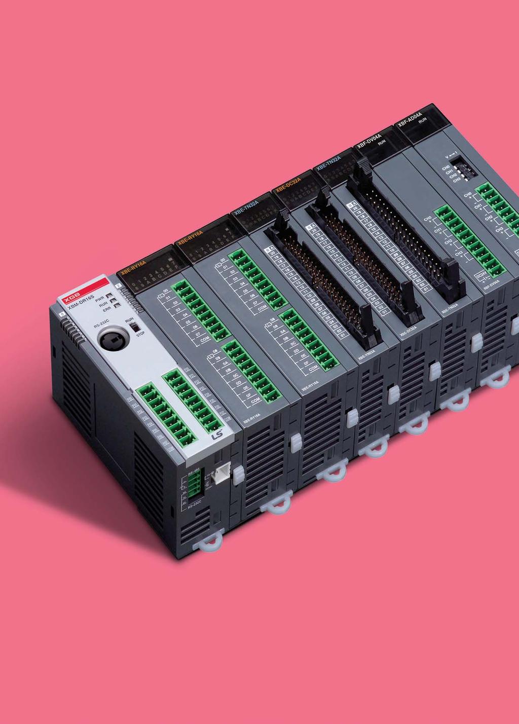
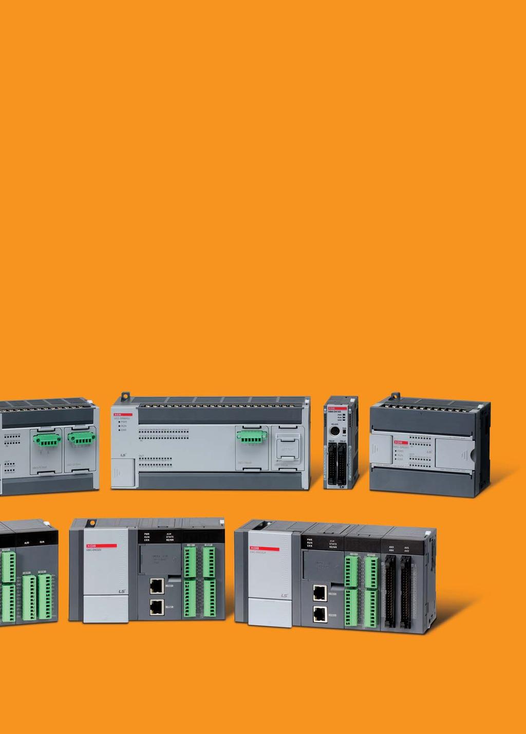
1 Programmable Logic Controller XGB Series

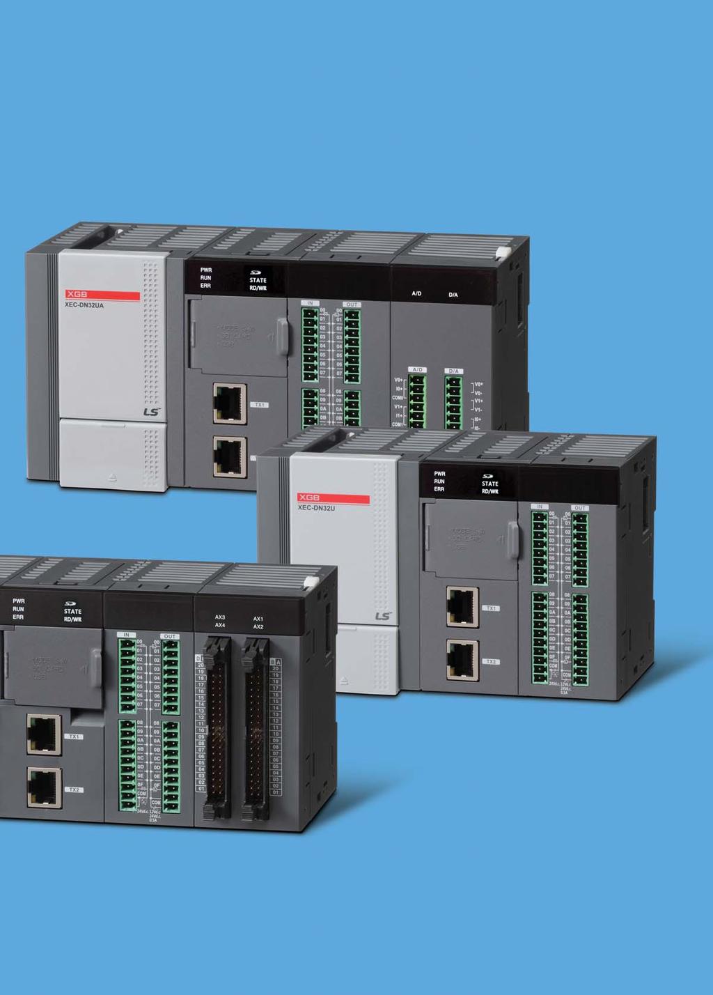
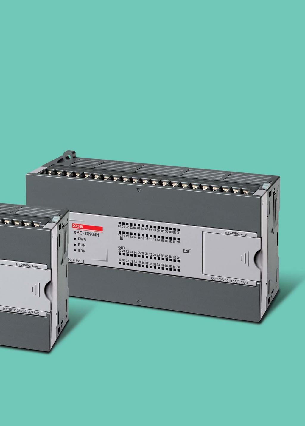
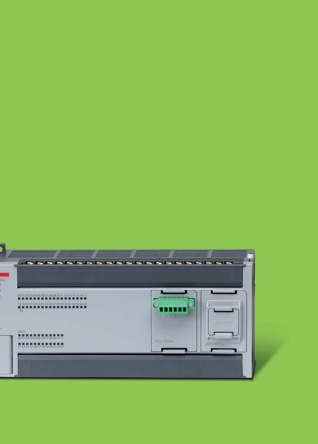
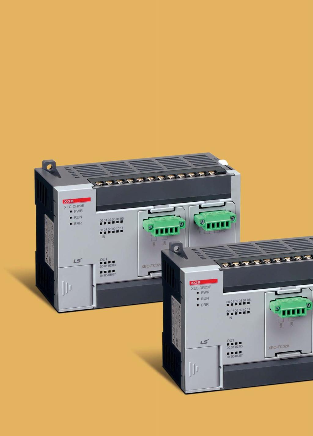
2 Programmable Logic Controller XGB U TYPE XBM Slim XBC/XEC H TYPE XBC/XEC E TYPE XBC/XEC SU TYPE 2
3 FEATURES 4 ~ 15 FEAT ATUR URES XBC/XEC U 16 ~ 23 XGB U Programmable Logic Controller XBC/XEC H 24 ~ 29 XBC/XEC SU 30 ~ 33 XBC/XEC E 40 ~ 47 XBM Slim 48 ~55 XBC/XEC H XBC/XEC SU XBC/XEC E XBM Slim APPLICATION 56 ~ 107 3

4 Intro AllInOne PLC With Next Generation Technology 4

5 XGB is a micro PLC that offers maximum performance at minimum cost. With its high functionality, XGB supports from simple control system to complex task. Strengthening its communication functions, XGB offers useroriented integrated control. Based on its strengths, XGB can be used in many application fields. 5
 1506490 1146490 1356490 1006490 306090 Expansion Special Module Communication Module Size(WHD) 206390")
6 Features Its Slim It s Powerful It s Slim Item Size(WHD) XBC/XEC U Type (Standard) XBC/XEC H Type XBC/XEC SU Type XBC/XEC E Type XBM Slim Type Size(WHD) Expansion Special Module Communication Module Size(WHD)

7 The actual size of the product It s Powerful Ethernet 1 Ch. (Dual Port) RS232C 1 Ch. RS485 1 Ch. PID Web Server Data Log USB Pulse catch High speed counter 8 Ch. Analog input/ output 8 Ch. Positioning 4 axes External interrupt XBC/XEC U Type 7
")
8 Features What you have dreamed of, we make it happen. XGB U sets new standards in Ultimate performance with its many innovations IoT (Internet of Things) realizes smart factories XGBU is a useroriented controller 8

9 Various Expansion Compatible with XGB expansion modules Max. 2 High speed backplane expansion modules Max. 10 expansion modules Max. 352 I/O points Expansion I/O module DC24 input, Transistor output, Relay output Special module Analog input, Analog output, RTD, Thermocouple, Highspeed counter, Positioning (Line drive 2 axes, EtherCAT network 8 axes) Communication modules RS232C, RS422/485, Ethernet, CANopen (Master/Slave), ProfibusDP (Master/Slave), DeviceNet (Slave), EtherNet/IP, RAPIEnet Expansion(XBC/XEC U Type) Max. 10 expansion modules Max. 2 High speed backplane modules Max. 2 Communication modules High speed Backplane I/F Interface Speed Basic I/F High speed Backplane I/F Communication Basic Data Log Easy parameter set up for [General save], [Trigger save], [Event save] without instruction 16GB of operation data storable Additional function SD memory format, FTP link, Diagnosis, Sending attached with a data log file PLC program upload/download O/S update 9
 Existing products XGB U Internet Daisy Chain Topology Daisy Chain Topology")

 SNTP Server SNTP client SNTP client SNTP client Gmail XGB Board")
10 Features Dual Port Ethernet(XBC/XEC U type) 2 ports unmanaged Ethernet switch support Cost saving through simple wiring FTP server support (Data logging) Existing products XGB U Internet Daisy Chain Topology Daisy Chain Topology Star Topology Web Server Monitoring of PLC information and data through web browser (PLC basic info., module info., diagnosis, device monitoring, flag monitoring, data log file download, O/S update, ladder program update, etc.) Time synchronization by setting basic parameters (SNTP: Simple Network Time Protocol) service through commercial (SMTP: Simple Mail Transfer Protocol) SNTP Server SNTP client SNTP client SNTP client Gmail XGB Board ESMTP ESMTP/ TLS ESMTP 10

11 Ultimate Performance Universal IoT User Oriented 11
 4Ch XBC/XEC H SU 100kHz(4Ch) 100kHz(2Ch) 20kHz(4Ch) 20kHz(6Ch) 8Ch 8Ch 50kHz(4Ch) 50kHz(1Ch) 10kHz(4Ch) 8kHz(3Ch) 4Ch 4Ch E 4kHz 4Ch 2kHz 2Ch XBM 20kHz 4Ch 2 multiplication: 10kHz 4")
12 Features U will experience the utmost efficiency for your applications with U s outstanding features Powerful builtin function Builtin high speed counter Phase 1 Phase 2 Phase U 100kHz(8Ch) 8Ch 50kHz(4Ch) 4Ch XBC/XEC H SU 100kHz(4Ch) 100kHz(2Ch) 20kHz(4Ch) 20kHz(6Ch) 8Ch 8Ch 50kHz(4Ch) 50kHz(1Ch) 10kHz(4Ch) 8kHz(3Ch) 4Ch 4Ch E 4kHz 4Ch 2kHz 2Ch XBM 20kHz 4Ch 2 multiplication: 10kHz 4 multiplication: 8kHz 2Ch 12

13 Builtin PID function It supports builtin PID control function up to 16 loops. It provides parameter setting using XG5000, convenient loop state monitoring through trend monitor. It can simply get a coefficient value by improved autotuning algorithm Control accuracy improvement by using various additional functions such as PWM output, MV, PV, SV Ramp, etc. It provides various control modes such as forward/reverse mixed operation, 2stage SV PID control, cascade control, etc. Various alarm functions such as MV high/low limit, PV high/low limit, PV variation Builtin analog I/O function (Available for XBC/XECDN32UA type only) Builtin analog input 4 channels (voltage/current, 14bit) Builtin analog output 4 channels (voltage/current 14bit) Builtin position control function (Available for XBC/XECDN32UP type only) Line drive output positioning function with up to 2Mpps 4axis Parameter set up by XGPM providing operation data edition, divers monitoring and diagnosis functions. High speed counter Pulse catch/input filter Positioning Encoder Sensor RS232C/485 Ethernet ModbusRTU/ASCII Servo drive Servo/Stapping motor 13
 XBC/XEC H Max.")
14 Features With its highspeed processing and system capability, XGB offers the utmost efficiency for your applications. XBC/XEC U Standard type Max. 10 stages (High speed interface module : Max. 2 stages) XBC/XEC H Max. 10 stage(including communication 2 stages) 14
, Battery DC 24V, Input 4 points TR")
15 XBC/XEC SU Option : Max. 2 stages (Only SU/E type) Max. 7 stage(expansion + Option), Communication Max. 2 stages XBC/XEC E XBOM2MB XBORTCA XBODC04A XBOTN04A XBOAD02A XBODA02A XBOAH02A XBORD01A XBOTC02A Option modules Memory / program READ/WRITE RTC (Real time clock), Battery DC 24V, Input 4 points TR (Sink), Output 4 points Voltage/Current, Input 2ch Voltage/Current, Output 2ch Voltage/Current, Input 1ch / Voltage/Current, Output 1ch RTD (Resistance temperature detector), Input 1ch TC (Thermo couple), Input 2ch Option : Max. 2 stages XBM Slim Max. 7 stage(communicaion Max. 2 stages) 15

16 XGB U Ultimate Performance Universal IoT User Oriented C o n t e n t s General specifications Performance specifications Wiring
17
18 General specifications Block type unit (U, H, SU, E) Item Ambient temperature Descriptions 0 ~ 55 C Standard Storage temperature 25 ~ + 70 C Ambient humidity 5 ~ 95%RH (Noncondensing) Storage humidity 5 ~ 95%RH (Noncondensing) Occasional vibration Frequency Acceleration Pulse width Vibration resistance 10 f < 57Hz 0.075mm 57 f 150Hz 9.8m/s 2 (1G) Continuous vibration Frequency Acceleration Pulse width 10 times each direction (X, Y and Z) IEC f < 57Hz 0.035mm 57 f 150Hz 4.9m/s 2 (0.5G) Shock resistance Peak acceleration: 147m/s 2 (15g) Duration: 11ms Pulse waveform: Halfsine, 3times each direction per each axis IEC Square wave impulse noise ±500 V LSIS Standard Electrostatic discharge 4kV IEC IEC Noise resistance Radiated electromagnetic field noise 80 ~ 1000MHz, 10V/m IEC IEC Operating ambience Altitude Pollution level *1) Cooling Fast transient/ Burst noise Main unit 2kV Expansion module 1kV Free from corrosive gases and excessive dust Up to 2,000m Less than 2 Aircooling IEC IEC *1) Pollution level indicates the degree to which conductive material is generated in the environment where the equipment is used. Pollution level 2 is the condition that only nonconductive pollution occurred but temporary conductivity may be produced due to condensing. 18
19 Performance specifications Block type unit XBC U Performance specifications Item XBCDN(P)32U Specifications XBCDR28U XBCDN(P)32UA XBCDR28UA XBCDN(P)32UP XBCDR28UP Remark Program control method Cyclic execution of stored program, Timedriven interrupt, Processdriven interrupt I/O control method Batch processing by simultaneous scan (Refresh method), Directed by program instruction Program language Number of instructions Basic Application Ladder Diagram, Instruction List XGB U Processing speed (Basic instruction) 60ns/step Program capacity 32Kstep Max. I/O points 352points 348points 352points 348points 352points 348points Main + 10 expansioons P P00000 ~ P2047F(32,768 point) Input/Ouput M M00000 ~ M2047F(32,768 point) K K00000 ~ K8191F(131,072 point) L L00000 ~ L4095F (65,536 point) Link F F00000 ~ F2047F (32,768 point) Flag Data area T C 100ms, 10ms, 1ms: T0000 ~ T2047 (2,048 point) C000 ~ C2047 (2,048 point) Timer Counter S S00.00 ~ S Step D D00000 ~ D19999(20000word) Data register U U00.00 ~ U0B.31 (384 word) Analog Data Z Z000~Z127 (128 word) N N0000~N10239(10,240 word) File register R RAM area 2 block (R0 ~ R16,383) FLASH area : 4 block (128Kbyte) Total program 256 Initial task 1 Cyclic task Max 16 Initial task I/O task Internal device task Max 8 Max 16 High Speed Counter task Max 8 Operation mode RUN, STOP, DEBUG Selfdiagnosis function Detects errors of scan time, memory, I/O and power supply Program port USB 1 channel, Ethernet Retain data at power failure Latch area setting in basic parameter Internal consumption current 700mA 990mA 780mA 1,040mA 1,250mA 1,550mA Weight 571g 630g 683g 732g 673g 722g *1) AutoMDIX (Automatic mediumdependent interface crossover) : It is the function to automatically detect whether the cable connected to the Ethernet port is peertopeer(straight) or cross cable 19
20 Performance specifications Block type unit XEC U Performance specifications Item Specifications XECDN(P)32U XECDR28U XECDN(P)32UA XECDR28UA XECDN(P)32UP XECDR28UP Remark Program control method Cyclic execution of stored program, Timedriven interrupt, Processdriven interrupt I/O control method Batch processing by simultaneous scan (Refresh method), Directed by program instruction Program language Ladder Diagram, Instruction List, SFC, ST Operator 18 Basic function Floatingpoint Arithmetic Functions Number of instructions Basic function block 43 Special function block Each special module has own special function blocks Processing speed (Basic instruction) 60ns/step Program memory 384Kbyte Max. I/O points 352points 348points 352points 348points 352points 348points Main + 10 expansioons Symbolic variable(a) 64KB (Retain setting available) Input variable(i) 2KB Output variable(q) 2KB M 32KB (Retain setting available) Data area Direct variable R W 32KB * 2blocks 64KB Same area with R F 4KB System flag K 16KB Keep relay Flag variable L U 8KB 768 Byte Link relay Analog data refresh area Flash area N 20KB 4blocks (128Kbyte) P2P parameter Using R device Timer No limit in points (Time range: 0.001~ 4,294, ) Counter No limit in points (Counter range: 64 bit range) Total program 256 Initial task 1 Cyclic task Max 16 Initial task 1 Initial task Cyclic task I/O task Max 16 Max 8 Internal device task Max 16 High Speed Counter task Max 8 Operation mode RUN, STOP, DEBUG Selfdiagnosis function Detects errors of scan time, memory, I/O and power supply Program port USB 1 channel Retain data at power failure Latch area setting in basic parameter Internal consumption current Weight 700mA 571g 990mA 630g 780mA 683g 1,040mA 732g 1,250mA 673g 1,550mA 722g 20
21 Built in function Programmable Logic Controller Builtin function Item XBC/XEC DN(P)32U XBC/XEC DR28U XBC/XEC DN(P)32UA Specifications XBC/XEC DR28UA XBC/XEC DN(P)32UP XBC/XEC DR28UP Remark PID control Seria Protocol Control by instruction, autotunning, PWM output, Forced output, Operation scan time setting, Antiwindup, Delta MV, PV tracking, Hybrid operation, Cascade operation Dedicated protocol, Modbus protocol User defined protocol, LS bus(inverter protocol) Embedded00 P2P:01 XGB U Channel RS232C 1 port and RS485 1 port Transfer spec Cable: 100BaseTX Speed: 100Mbps AutoMDIX *1 IEEE Ethernet Topology Diagnosis Line, star Module information, service condition Protocol Service XGT dedicated Modbus TCP/IP user define frame P2P, High Speed link, Remote connection Embedded01 P2P:02 Highspeed link:01 Datalog Group Data set Extension File size SD memory type Memory size File system Max 10 group 32 per group csv file Max 16Mbyte SD,SDHC type(recommand: SanDisk,Transcend) Max 16GB FAT32 Performance 1phase : 100KHz 8 channels 2phase : 50KHz 4 channels High Speed Counter Counter mode 4 counter modes are supported based on input pulse and I/DEC method 1 pulse operation Mode : I/DEC count by program 1 pulse operation Mode : I/DEC count by phase B pulse input 2 pulse operation Mode : I/DEC count by input pulse 2 pulse operation Mode : I/DEC count by difference of phase Function Internal/external preset Latch counter Compare output of rotation per unit time *1) AutoMDIX(Automatic mediumdependent interface crossover) : It is the function to automatically detect whether the cable connected to the Ethernet port is peertopeer(straight) or cross cable 21
22 Performance specifications Built in function XEC U Positioning Item Specifications Remark Basic Function interpolation of control axi: 4axis Control Method:Position, Speed, Speed/Position,Feed Control Control Unit: Pulse,mm, inch, degree Positioning Data: Each axis can have up to 400 data(step number:1~400) Operation pattern: End, Keep, Continuous Operation method: Singular, Repeat 2/3/4 axis linear interpolation 2 axis circular interpolation 3 axis helical interpolation Positioning Method: Absolute/Incremental method Address range: 2,147,483,648~2,147,483,647 Speed: Max 2Mpps(1~2,000,000pps) Acc /Dec process: Trapezoid type, Stype Available On UP type Homing method DOG+HOME(Off), DOG+HOME(On), Upper limit + HOME,DOG, High speed, Upper/Lower limit, HOME Manual operation Encoder input Jog operation, MPG operation, Inching operation Line drive(rs422a) input 1Channel(Max 200kpps) Analog Analog input Analog output Item Specifications Remark Channels Specification Channels Specification Input Range Input resistance Max.Resolution Accuracy Output Range Load resistance Max.Resolution 4channels (current/voltage) Voltage: 1~5V, 0~5V, 0~10V, 10~10V, Current: 4~20,0~20 Current input or Voltage input can be selected through the external terminal wiring setting. 1 or more(voltage input), 250 (current iput) 1/ mV(1 ~ 5V), mV(0 ~ 5V) 0.625mV(0 ~ 10V), 1.250mV(±10V) 0.250mV(1 ~ 5V), mV(0 ~ 5V) 0.625mV(0 ~ 10V), 1.250mV(±10V) 1.0 (4 ~ 20 ) 1.25 (0 ~ 20 ) ±0.2% or less (When ambient temperature is 25 ) ±0.3% or less (When ambient temperature is 0 ~ 55 ) Voltage 2 channels,current 2 channels Voltage: 1~5V, 0~5V, 0~10V, 10~10V, Current: 4~20,0~20 Output ranges are set in user program or I/O parameter per each channel. 1 or more(voltage output), 600 or less(current output) 1/ (4 ~ 20 ) 1.25 (0 ~ 20 ) Available On UP type Accuracy ±0.2% or less (When ambient temperature is 25 ) ±0.3% or less (When ambient temperature is 0 ~ 55 ) 22
23 Wiring XGB U input/output wiring Programmable Logic Controller XBCDN(P)32U (16 point input) TB1 TB8 TB9 Circuit configuration TB1 TB2 TB3 TB4 TB5 TB6 TB7 TB8 Contact Contact Type TB1 8 TB2 9 TB3 A TB4 B TB5 C TB6 D TB7 E TB8 F TB9 COM XGB U TB10 COM XBCDN32U Transistor output (Sink type) Circuit configuration TB1 TB8 TB9 TB10 TB1 TB2 TB3 TB4 TB5 TB6 TB7 TB8 TB1 TB2 TB3 TB4 TB5 TB6 TB7 TB8 TB9 TB10 Contact A B C D E F DC12/24V COM Type 23
24 XBC/XEC H High Performance C o n t e n t s Performance specifications Wiring 26 27
25
26 Performance specifications Block type unit High performance type Performance specifications Item Control method I/O control method Programming language Processing speed Program capacity Main unit I/O points XBC/XECDR32H XBCDR32H/ DC *1) XECDR32H/ DI XBC/XECDN32H XECDP32H *1) XBCDN32H/DC XBC/XECDR64H XBCDR64H/DC *1) XECDR64H/DI XBC/XECDN64H XECDP64H *1) XBCDN64H/DC Repetitive, cyclic, interrupt, constant scan Refresh mode (Batch processing by scan synchronization), Direct mode by instruction Ladder diagram or IEC standard (LD, SFC, ST) *1) 83 ns / Step 15Kstep (IEC type: 200KB) (Input:16, Output:16) (Input:16, Output:16) (Input: 32, Output: 32) (Input: 32, Output: 32) Max. I/O points (Main + Expansion 10 stages) 352 points 384 points Total program Operation mode Self diagnosis Program port Retain data at power failure Builtin functions 128 RUN, STOP, DEBUG Detects errors of scan time, memory error, I/O error, battery error, power error, etc. USB (Rev 1.1), RS232C 1 channel (Loader) Latch area setting at basic parameter RS232C / RS485(2 ch), Pulse catch, Input filter, External interrupt, PID control, Highspeed counter, Positioning, RTC Data memory XBC XEC (IEC type) P P0000 ~ P1023F (16,384 points) Symbolic variable A 32KB (Max. 16KB retain setting available) M M0000 ~ M1023F (16,384 points) Input variable I 2KB(%IX ) K K0000 ~ K4095F (65,536 points) Output variable Q 2KB(%QX ) L L0000 ~ L2047F (32,768 points) M 16KB (Max. 8KB retain setting available) F F0000 ~ F1023F (16,384 points) Direct variable R 20KB (1 block) T 100ms, 10ms, 1ms: T0000 ~ T1023 (1,024)(Adjustable by parameter setting) W 20KB C C0000 ~ C1023 (1,024) F 2KB S S00.00 ~ S K 8KB D D0000 ~ D10239 (10,240 word) L 4KB Flag variable U00.00 ~ U0A.31 U N 10KB (Analog data refresh area: 352 word) Z Z000 ~ Z127 (128 word) U 1KB N N000 ~ N5119 (5,120 word) Flash area R 20KB (2 blocks) *1) XEC is IEC standard language programming. 26
27 Wiring XBC/XEC H input/output wiring XBC/XECDN(R)32H XBC/XECDN/DR/DP32H Input wiring (sink/source type) XBC/XECDR32H Relay output wiring type Circuit configuration Circuit configuration TB2 TB4 TB6 TB8 TB10 TB12 TB14 TB16 TB18 TB20 TB22 TB24 TB2 TB4 TB6 TB8 TB10 TB12 TB14 TB16 TB18 TB20 TB22 TB24 Contact A 0C 0E COM 24V Contact PE C0M C 2E C0M3 Contact Type TB1 TB3 TB5 TB7 TB9 TB11 TB13 TB15 TB17 TB19 TB21 TB23 RX TX SG B 0D 0F 24G Contact Type TB1 TB3 TB5 TB7 TB9 TB11 TB13 TB15 TB17 TB19 TB21 TB23 Power C0M A C0M2 2D 2F XBC/XEC H XBC/XECDN32H Transistor output wiring (sink type) Circuit configuration TB2 TB4 TB6 TB8 TB10 TB12 TB14 TB16 TB18 TB20 TB22 TB24 Contact PE DC12/24V C0M C 2E C0M3 Contact Type TB1 TB3 Power TB5 20 DC12/ 24V TB7 22 TB9 C0M0 TB11 25 TB13 27 TB15 28 TB17 2A TB19 C0M2 TB21 2D TB23 2F * XBC input : P00~P1F, XEC input : I00~I31 * XBC output : P21~P3F, XEC output : Q00~Q31 27
28 Wiring XBC/XEC H input/output wiring XECDP32H Transistor output wiring (source type) Circuit configuration TB2 TB4 TB6 TB8 TB10 TB12 TB14 TB16 TB18 TB20 TB22 TB24 Contact PE DC12/24V C0M C 2E C0M3 Contact Type TB1 TB3 Power TB5 DC12/ 20 24V TB7 22 TB9 C0M0 TB11 25 TB13 27 TB15 28 TB17 2A TB19 C0M2 TB21 2D TB23 2F XBCDN(R)64H XECDN/DR/DP64H Input wiring (sink/source type) Circuit configuration TB2 TB4 TB6 TB8 TB10 TB12 TB14 TB16 TB18 TB20 TB22 TB24 TB26 TB28 TB30 TB32 TB34 TB36 TB38 TB40 TB42 Contact A 0O 0E C0M A 1C 1E C0M1 24V Contact Type TB1 RX TB3 TX TB5 SG TB7 01 TB9 03 TB11 05 TB13 07 TB15 09 TB17 0B TB19 0D TB21 0F TB23 MC TB25 11 TB27 13 TB29 15 TB31 17 TB33 19 TB35 1B TB37 1D TB39 1F TB41 24G XBCDR60H XECDR64H Relay output wiring Circuit configuration TB2 TB4 TB6 TB8 TB10 TB12 TB14 TB16 TB18 TB20 TB22 TB24 TB26 TB28 TB30 TB32 TB34 TB36 TB38 TB40 TB42 Contact PE COM1 29 2B 2C 2E COM A 3C 3E COM5 Contact Type TB1 TB3 Power TB5 20 TB7 22 TB9 COM0 TB11 25 TB13 27 TB15 28 TB17 2A TB19 COM2 TB21 2D TB23 2F TB25 30 TB27 32 TB29 34 TB31 36 TB33 COM4 TB35 39 TB37 38 TB39 3D TB41 3F * XBC input : P00~P1F, XEC input : I00~I31 * XBC output : P21~P3F, XEC output : Q00~Q31 28
29 Programmable Logic Controller XBCDP64H Transistor output wiring (sink type) Circuit configuration TB2 TB4 TB6 TB8 TB10 TB12 TB14 TB16 TB18 TB20 TB22 TB24 TB26 TB28 TB30 TB32 TB34 TB36 TB38 TB40 TB42 Contact PE DC12/24V COM1 29 2B 2C 2E COM A 3C 3E COM5 Contact Type TB1 TB3 TB5 TB7 TB9 TB11 TB13 TB15 TB17 TB19 TB21 TB23 TB25 TB27 TB29 TB31 TB33 TB35 TB37 TB39 TB41 Power COM A COM2 2D 2F COM D 3F DC12/24V XBC/XEC H XBCDP64H Transistor output wiring (source type) Circuit configuration TB2 TB4 TB6 TB8 TB10 TB12 TB14 TB16 TB18 TB20 TB22 TB24 TB26 TB28 TB30 TB32 TB34 TB36 TB38 TB40 TB42 Contact PE DC12/24V COM1 29 2B 2C 2E COM A 3C 3E COM5 Contact Type TB1 TB3 TB5 TB7 TB9 TB11 TB13 TB15 TB17 TB19 TB21 TB23 TB25 TB27 TB29 TB31 TB33 TB35 TB37 TB39 TB41 Power COM A COM2 2D 2F COM D 3F * XBC input : P00~P1F, XEC input : I00~I31 * XBC output : P21~P3F, XEC output : Q00~Q31 29

30 XBC/XEC SU Standard C o n t e n t s Performance specifications Wiring 32 33
31
32 Performance specifications Block type unit Standard type Performance specifications Item Control method I/O control method Programming language Processing speed Program capacity Main unit I/O points Max. I/O points (Main + Expansion 7 stages) Total program Operation mode Self diagnosis Program port Retain data at power failure Builtin functions XBC/XECDN20SU XBC/XECDR20SU XBC/XECDP20SU XBC/XECDN30SU XBC/XECDN40SU XBC/XECDR30SU XBC/XECDR40SU XBC/XECDP30SU XBC/XECDP40SU Repetitive, cyclic, interrupt, constant scan Refresh mode (Batch processing by scan synchronization), Direct mode by instruction 20 (Input:12, Output:8) Ladder diagram, Instruction List 94 ns / Step 15Kstep / 200KB 30 (Input:18, Output:12) 40 (Input:24, Output:16) XBC/XECDN60SU XBC/XECDR60SU XBC/XECDP60SU 60 (Input:36, Output:24) 244 points 254 points 264 points 284 points 128 RUN, STOP, DEBUG Detects errors of scan time, memory error, I/O error, battery error, power error, etc. RS232C 1 channel (Loader), USB 1 channel (Utype model) Latch area setting at basic parameter RS232C / RS485(2 ch), Pulse catch, Input filter, External interrupt, PID control, Highspeed counter, Positioning Data memory XBC XEC Data area P M K L F T C S D U Z P0000 ~ P1023F (16,384 points) M0000 ~ M1023F (16,384 points) K0000 ~ K4095F (65,536 points) L0000 ~ L2047F (32,768 points) F0000 ~ F1023F (16,384 points) 100ms, 10ms, 1ms: T0000 ~ T1023 (1,024) (Adjustable by parameter setting) C0000 ~ C1023 (1,024) S00.00 ~ S D0000 ~ D10239 (10,240 word) U00.00 ~ U0A.31 (Analog data refresh area: 352 word) Z000 ~ Z127 (128 word) Symbolic variable Input variable Output variable A I Q M Direct variable R W F Flag K variable L U Flash area 16KB (Max. 16KB retain setting abailable) 2KB (%IX ) 2KB (%QX ) 8KB (Max. retain setting available) 20KB (1 block) 20KB 2KB 8KB 4KB 1KB 20KB (2 block) R N0000 ~ N10236 (10,240 word) *Some products are due in market soon. 32
33 Wiring XBC/XEC SU input/output wiring XBC/XECDR20SU XBC/XECDN20SU XBC/XECDP20SU Input wiring (sink/source type) Circuit configuration TB2 TB4 TB6 TB8 TB10 TB12 TB14 TB16 TB18 TB20 TB22 TB24 Contact A COM Contact Type TB1 TB3 TB5 TB7 TB9 TB11 TB13 TB15 TB17 TB19 TB21 TB23 RX TX SG B XBC/XECDR20SU Relay output wiring Circuit configuration TB2 TB4 TB6 TB8 TB10 TB12 TB14 TB16 TB18 TB20 TB22 TB24 Contact PE C0M0 C0M1 C0M2 43 COM G Contact Type TB1 TB3 TB5 TB7 TB9 TB11 TB13 TB15 TB17 TB19 TB21 TB23 AC V V XBC/ C/XE XEC SU XBC/XECDN20SU Transistor output wiring (sink type) Circuit configuration TB2 TB4 TB6 TB8 TB10 TB12 TB14 TB16 TB18 TB20 TB22 TB24 Contact PE COM0 COM1 COM2 43 COM G Contact Type TB1 TB3 TB5 TB7 TB9 TB11 TB13 TB15 TB17 TB19 TB21 TB23 AC V P V * XBC input : P00~P23, XEC input : I00~I35 * XBC output : P40~P57, XEC output : Q00~Q23 33
34 Wiring XBC/XEC SU input/output wiring XBC/XECDP32H Transistor output wiring (source type) Circuit configuration TB2 TB4 TB6 TB8 TB10 TB12 TB14 TB16 TB18 TB20 TB22 TB24 Contact PE C0M0 C0M1 C0M2 Q03 COM3 Q05 Q07 24G Contact Type TB1 TB3 TB5 TB7 TB9 TB11 TB13 TB15 TB17 TB19 TB21 TB23 AC V Q00 Q01 Q02 N Q04 Q06 24V XBC/XECDR30SU XBC/XECDN30SU XBC/XECDP30SU Input wiring (sink/source type) Circuit configuration TB2 TB4 TB6 TB8 TB10 TB12 TB14 TB16 TB18 TB20 TB22 TB24 Contact A 0C 0E 10 COM Contact Type TB1 TB3 TB5 TB7 TB9 TB11 TB13 TB15 TB17 TB19 TB21 TB23 RX TX SG B 0D 0F 11 XBC/XECDR30SU Relay output wiring Circuit configuration TB2 TB4 TB6 TB8 TB10 TB12 TB14 TB16 TB18 TB20 TB22 TB24 Contact PE COM0 COM1 COM2 43 COM COM4 49 4B 24G Contact Type TB1 TB3 TB5 TB7 TB9 TB11 TB13 TB15 TB17 TB19 TB21 TB23 AC V A 24V * XBC input : P00~P23, XEC input : I00~I35 * XBC output : P40~P57, XEC output : Q00~Q23 34
35 Programmable Logic Controller XBC/XECDN30SU Transistor output wiring (sink type) Circuit configuration TB2 TB4 TB6 TB8 TB10 TB12 TB14 TB16 TB18 TB20 TB22 TB24 Contact PE COM0 COM1 COM2 43 COM COM4 49 4B 24G Contact Type TB1 TB3 TB5 TB7 TB9 TB11 TB13 TB15 TB17 TB19 TB21 TB23 AC V P A 24V XBC/XECDP30SU Transistor output wiring (source type) Circuit configuration TB2 TB4 TB6 TB8 TB10 TB12 TB14 TB16 TB18 TB20 TB22 TB24 Contact PE COM0 COM1 COM2 Q03 COM3 Q05 Q07 COM4 Q09 Q11 24G Contact Type TB1 TB3 TB5 TB7 TB9 TB11 TB13 TB15 TB17 TB19 TB21 TB23 AC V Q00 Q01 Q02 N Q04 Q06 Q08 Q10 24V XBC/ C/XE XEC SU XBC/XECDR40SU XBC/XECDN40SU XBC/XECDP40SU DC24 Input wiring (sink/source type) Circuit configuration TB2 TB4 TB6 TB8 TB10 TB12 TB14 TB16 TB18 TB20 TB22 TB24 TB26 TB28 TB30 Contact A 0C 0E COM Contact Type TB1 TB3 TB5 TB7 TB9 TB11 TB13 TB15 TB17 TB19 TB21 TB23 TB25 TB27 TB29 RX TX SG B 0D 0F * XBC input : P00~P23, XEC input : I00~I35 * XBC output : P40~P57, XEC output : Q00~Q23 35
36 Wiring XBC/XEC SU input/output wiring XBC/XECDR40SU Relay output wiring Circuit configuration TB2 TB4 TB6 TB8 TB10 TB12 TB14 TB16 TB18 TB20 TB22 TB24 TB26 TB28 TB30 Contact PE C0M0 C0M1 C0M2 43 COM COM4 49 4B COM5 4D 4F 24G Contact Type TB1 TB3 TB5 TB7 TB9 TB11 TB13 TB15 TB17 TB19 TB21 TB23 TB25 TB27 TB29 AC V A 4C 4E 24V XBC/XECDN40SU Transistor output wiring (sink type) Circuit configuration TB2 TB4 TB6 TB8 TB10 TB12 TB14 TB16 TB18 TB20 TB22 TB24 TB26 TB28 TB30 Contact PE C0M0 C0M1 C0M2 43 COM COM4 49 4B COM5 4D 4F 24G Contact Type TB1 TB3 TB5 TB7 TB9 TB11 TB13 TB15 TB17 TB19 TB21 TB23 TB25 TB27 TB29 AC V P A 4C 4E 24V XBC/XECDP40SU Transistor output wiring (source type) Circuit configuration TB2 TB4 TB6 TB8 TB10 TB12 TB14 TB16 TB18 TB20 TB22 TB24 TB26 TB28 TB30 Contact PE C0M0 C0M1 C0M2 03 COM COM COM G Contact Type TB1 TB3 TB5 TB7 TB9 TB11 TB13 TB15 TB17 TB19 TB21 TB23 TB25 TB27 TB29 AC V N V * XBC input : P00~P23, XEC input : I00~I35 * XBC output : P40~P57, XEC output : Q00~Q23 36
37 Programmable Logic Controller XBC/XECDR60SU XBC/XECDN60SU XBC/XECDP60SU Input wiring (sink/source type) XBC/XECDR60SU Relay output wiring Circuit configuration Circuit configuration TB2 TB4 TB6 TB8 TB10 TB12 TB14 TB16 TB18 TB20 TB22 TB24 TB26 TB28 TB30 TB32 TB34 TB36 TB38 TB40 TB42 TB2 TB4 TB6 TB8 TB10 TB12 TB14 TB16 TB18 TB20 TB22 TB24 TB26 TB28 TB30 TB32 TB34 TB36 TB38 TB40 TB42 Contact A 0C 0E A 1C 1E COM Contact PE C0M0 C0M1 C0M2 43 COM COM4 49 4B COM5 4D 4F COM COM G Contact Type TB1 TB3 TB5 TB7 TB9 TB11 TB13 TB15 TB17 TB19 TB21 TB23 TB25 TB27 TB29 TB31 TB33 TB35 TB37 TB39 TB41 RX TX SG B 0D 0F B 1D 1F Contact Type TB1 AC100 TB3 240V TB5 40 TB7 41 TB9 42 TB11 TB13 44 TB15 46 TB17 TB19 48 TB21 4A TB23 TB25 4C TB27 4E TB29 TB31 50 TB33 52 TB35 TB37 54 TB39 56 TB41 24V XBC/ C/XE XEC SU * XBC input : P00~P23, XEC input : I00~I35 * XBC output : P40~P57, XEC output : Q00~Q23 37
38 Wiring XBC/XEC SU input/output wiring XBC/XECDN60SU Transistor output wiring (sink type) Circuit configuration TB2 TB4 TB6 TB8 TB10 TB12 TB14 TB16 TB18 TB20 TB22 TB24 TB26 TB28 TB30 TB32 TB34 TB36 TB38 TB40 TB42 Contact PE C0M0 C0M1 C0M2 43 COM COM4 49 4B COM5 4D 4F COM COM G Contact Type TB1 AC100 TB3 240V TB5 40 TB7 41 TB9 42 TB11 P TB13 44 TB15 46 TB17 TB19 48 TB21 4A TB23 TB25 4C TB27 4E TB29 TB31 50 TB33 52 TB35 TB37 54 TB39 56 TB41 24V XBC/XECDP60SU Transistor output wiring (source type) Circuit configuration TB2 TB4 TB6 TB8 TB10 TB12 TB14 TB16 TB18 TB20 TB22 TB24 TB26 TB28 TB30 TB32 TB34 TB36 TB38 TB40 TB42 Contact PE C0M0 C0M1 C0M2 03 COM COM COM COM COM G Contact Type TB1 TB3 TB5 TB7 TB9 TB11 TB13 TB15 TB17 TB19 TB21 TB23 TB25 TB27 TB29 TB31 TB33 TB35 TB37 TB39 TB41 AC V N V * XBC input : P00~P23, XEC input : I00~I35 * XBC output : P40~P57, XEC output : Q00~Q23 38
39 Programmable Logic Controller XBC/XEC SU 39
40

41 XBC/XEC E Economic C o n t e n t s Performance specifications Wiring 42 43
42 Performance specifications Block type unit Economic Performance specifications Item Program control method I/O control method Program language Processing speed (Basic instruction) Program capacity Max. I/O points (Main+Option X ) Operation Mode Total number of program block Initialization Fixed period Task External input Internal device Program port Self diagnostic functions Built in functions Retain data at power failure XBC/XECDR10E XBC/XECDN10E XBC/XECDP10E Specifications ( E type) XBC/XECDR14E XBC/XECDN14E XBC/XECDP14E XBC/XECDR20E XBC/XECDN20E XBC/XECDP20E Reiterative operation, Fixed cycle operation Ladder Diagram (LD), Sequential Function Chart (SFC) Structured Text (ST), Instruction List (IL) XBC/XECDR30E XBC/XECDN30E XBC/XECDP30E Scan synchronized batch processing method (Refresh method) Direct method by instruction 14 point (1 option) 18 point (1 option) 240 ns /step 4 Kstep (XBCD E), 50 KB (XECD E) 28 point (2 option) 38 point (2 option) RUN, STOP, DEBUG (%I 0.0.0~%I 0.0.3) 8 RS232C 1 channel (Loader) Watchdog Timer, Memory error detection I/O error detection, etc. RS232C or RS485(1 ch), Pulse catch, Input filter, External interrupt, Highspeed counter Latch area setting at basic parameter 42
43 Wiring XBC/XEC E input/output wiring XBC/XECDR10E XBC/XECDN10E XBC/XECDP10E Input iring (sink/source type) Circuit configuration TB2 TB4 TB6 TB8 TB10 TB12 TB14 Contact COM Contact Type TB1 TB3 TB5 TB7 TB9 TB11 TB13 RX TX SG XBC/XECDR10E Relay output wiring Circuit configuration TB2 TB4 TB6 TB8 TB10 TB12 TB14 Contact PE COM0 COM1 COM G Contact Type TB1 AC100 TB3 240V PE TB5 40 TB7 41 TB9 42 TB11 TB13 24V XBC/XECDN10E Transistor output wiring (sink type) Circuit configuration TB2 TB4 TB6 TB8 TB10 TB12 TB14 Contact PE P COM0 COM G Contact Type TB1 TB3 TB5 TB7 TB9 TB11 TB13 AC V V XBC/XEC E XBC/XECDP10E Transistor output wiring (source type) Circuit configuration TB2 TB4 TB6 TB8 TB10 TB12 TB14 Contact PE N COM0 COM G Contact Type TB1 TB3 TB5 TB7 TB9 TB11 TB13 AC100 ~240V V * XBC input : P00~P11, XEC input : I00~I17 * XBC output : P40~P4B, XEC output : Q00~Q11 43
44 Wiring XBC/XEC E input/output wiring XBC/XECDR14E XBC/XECDN14E XBC/XECDP14E Input iring (sink/source type) Circuit configuration TB2 TB4 TB6 TB8 TB10 TB12 TB14 Contact COM Contact Type TB1 TB3 TB5 TB7 TB9 TB11 TB13 RX TX SG XBCDR14E Relay output wiring Circuit configuration TB2 TB4 TB6 TB8 TB10 TB12 TB14 Contact PE COM0 COM1 COM G Contact Type TB1 AC100 TB3 240V PE TB5 40 TB7 41 TB9 42 TB11 TB13 24V XBC/XECDN14E Transistor output wiring (sink type) Circuit configuration TB2 TB4 TB6 TB8 TB10 TB12 TB14 Contact PE P COM0 COM G Contact Type TB1 TB3 TB5 TB7 TB9 TB11 TB13 AC V V XBC/XECDP14E Transistor output wiring (source type) Circuit configuration TB2 TB4 TB6 TB8 TB10 TB12 TB14 Contact Contact Type TB1 TB3 TB5 TB7 TB9 TB11 TB13 AC V V * XBC input : P00~P11, XEC input : I00~I17 * XBC output : P40~P4B, XEC output : Q00~Q11 44
45 Programmable Logic Controller XBC/XECDR20E XBC/XECDN20E XBC/XECDP20E Input iring (sink/source type) Circuit configuration TB2 TB4 TB6 TB8 TB10 TB12 TB14 TB16 TB18 TB20 TB22 TB24 Contact A COM Contact Type TB1 TB3 TB5 TB7 TB9 TB11 TB13 TB15 TB17 TB19 TB21 TB23 RX TX SG B XBCDR20E Relay output wiring Circuit configuration TB2 TB4 TB6 TB8 TB10 TB12 TB14 TB16 TB18 TB20 TB22 TB24 Contact PE COM0 COM1 COM G Contact Type TB1 TB3 TB5 TB7 TB9 TB11 TB13 TB15 TB17 TB19 TB21 TB23 PE XBC/XECDN20E Transistor output wiring (sink type) Circuit configuration TB2 TB4 TB6 TB8 TB10 TB12 TB14 TB16 TB18 TB20 TB22 TB24 Contact PE P COM0 COM1 03 COM G Contact Type TB1 TB3 TB5 TB7 TB9 TB11 TB13 TB15 TB17 TB19 TB21 TB23 AC V V XBC/XEC E XBC/XECDP20E Transistor output wiring (source type) Circuit configuration TB2 TB4 TB6 TB8 TB10 TB12 TB14 TB16 TB18 TB20 TB22 TB24 Contact PE N COM0 COM1 03 COM G Contact Type TB1 TB3 TB5 TB7 TB9 TB11 TB13 TB15 TB17 TB19 TB21 TB23 AC V V * XBC input : P00~P11, XEC input : I00~I17 * XBC output : P40~P4B, XEC output : Q00~Q11 45
46 Wiring XBC/XEC E input/output wiring XBC/XECDR30E XBC/XECDN30E XBC/XECDP30E Input iring (sink/source type) Circuit configuration TB2 TB4 TB6 TB8 TB10 TB12 TB14 TB16 TB18 TB20 TB22 TB24 Contact A OC OE 10 COM Contact Type TB1 TB3 TB5 TB7 TB9 TB11 TB13 TB15 TB17 TB19 TB21 TB23 RX TX SG B OD OF 11 XBCDR30E Relay output wiring Circuit configuration TB2 TB4 TB6 TB8 TB10 TB12 TB14 TB16 TB18 TB20 TB22 TB24 Contact PE COM0 COM1 COM2 43 COM COM4 49 4B 24G Contact Type TB1 TB3 TB5 TB7 TB9 TB11 TB13 TB15 TB17 TB19 TB21 TB23 PE XBC/XECDN30E Transistor output wiring (sink type) Circuit configuration TB2 TB4 TB6 TB8 TB10 TB12 TB14 TB16 TB18 TB20 TB22 TB24 Contact PE P COM0 COM1 03 COM COM G Contact Type TB1 TB3 TB5 TB7 TB9 TB11 TB13 TB15 TB17 TB19 TB21 TB23 AC V V XBC/XECDP30E Transistor output wiring (source type) Circuit configuration TB2 TB4 TB6 TB8 TB10 TB12 TB14 TB16 TB18 TB20 TB22 TB24 Contact PE N COM0 COM1 03 COM COM G Contact Type TB1 TB3 TB5 TB7 TB9 TB11 TB13 TB15 TB17 TB19 TB21 TB23 AC V V * XBC input : P00~P11, XEC input : I00~I17 * XBC output : P40~P4B, XEC output : Q00~Q11 46
47 Programmable Logic Controller XBC/XEC E 47
48 XBM Slim Slim C o n t e n t s General specification Performance specifications Wiring
49
 Storage humidity 5 ~ 95%RH (Noncondensing) Occasional vibration Frequency Acceleration Pulse width Vibration resistance 10 f < 57Hz 0.075mm 57 f 150Hz 9.")
50 General specification Slim Modular type unit (XBMDR16S, DN16S, DN32S) Item Ambient temperature Descriptions 0 ~ 55 C Standard Storage temperature 25 ~ + 70 C Ambient humidity 5 ~ 95%RH (Noncondensing) Storage humidity 5 ~ 95%RH (Noncondensing) Occasional vibration Frequency Acceleration Pulse width Vibration resistance 10 f < 57Hz 0.075mm 57 f 150Hz 9.8m/s 2 (1G) Continuous vibration Frequency Acceleration Pulse width 10 times each direction (X, Y and Z) IEC f < 57Hz 0.035mm 57 f 150Hz 4.9m/s 2 (0.5G) Shock resistance Peak acceleration: 147m/s 2 (15g) Duration: 11ms Pulse waveform: Halfsine, 3times each direction per each axis IEC Square wave impulse noise ±500 V LSIS Standard Electrostatic discharge 4kV IEC IEC Noise resistance Radiated electromagnetic field noise 80 ~ 1000MHz, 10V/m IEC IEC Operating ambience Altitude Pollution level *1) Cooling Fast transient/ Burst noise Main unit 2kV Expansion module 1kV Free from corrosive gases and excessive dust Up to 2,000m Less than 2 Aircooling IEC IEC *1) Pollution level indicates the degree to which conductive material is generated in the environment where the equipment is used. Pollution level 2 is the condition that only nonconductive pollution occurred but temporary conductivity may be produced due to condensing. 50
51 Performance specifications Modular type unit Performance specifications Control method I/O control method Programming language Processing speed Program capacity Main unit I/O points Item XBMDR16S XBMDN16S XBMDN32S Max. I/O points (Main + Expansion 7 stages) Total program Operation mode Self diagnosis Program port Retain data at power failure Built in functions Repetitive, cyclic, fixed cycle operation, constant scan Refresh mode (Batch processing by scan synchronization), Direct mode by instruction 16 points (Input:8, Output:8) Ladder diagram, Instruction List 160 ns/step 10Kstep Data memory 16 points (Input:8, Output:8) 32 points (Input:16, Output:16) 240 points 256 points 128 RUN, STOP, DEBUG Detects errors of scan time, memory error, I/O error, battery error, power error, etc. RS232C 1 channel (Loader) Latch area setting at basic parameter RS232C/RS485(2 ch), Pulse catch, Input filter, External interrupt, PID control, Highspeed counter, Positioning *1) Data area P M K L F T C S D U Z N XBM P0000 ~ P127F (2,048 points) M0000 ~ M255F (4,096 points) K0000 ~ K2559F (Special area: K2600~K2559F) (40,960 points) L0000 ~ L1279F (20,480 points) F000 ~ F255F (4,096 points) 100ms, 10ms, 1ms: T000 ~ T255 (256) (Adjustable by parameter setting) C000 ~ C255 (256) S00.00 ~ S D0000 ~ D5119 (5,120 word) U00.00 ~ U07.31 (Analog data refresh area: 256 word) Z000 ~ Z127 (128 word) N0000 ~ N3935 (3,936 word) *1) XBMDR16S does not have builtin positioning function. XBM Slim 51
52 Wiring XGB Slim input/output wiring XBMDR16S Input wiring (sink/source type) Circuit configuration Contact Type TB1 0 TB2 1 TB3 2 TB4 3 TB5 4 TB6 5 TB7 6 TB8 7 TB9 COM XBMDR16S Relay output wiring Circuit configuration TB1 Contact 20 Type TB2 21 TB3 22 TB4 23 TB5 24 TB6 25 TB7 26 TB8 TB9 27 COM XBMDN16S Input wiring(sink/source type) Circuit configuration Contact Contact Type B10 B09 B08 B07 B06 B05 B04 B03 B02 B COM COM A10 A09 A08 A07 A06 A05 A04 A03 A02 A01 52
53 Programmable Logic Controller XBMDR16S Transistor output wiring (sink type) Circuit configuration Contact Type B10 B09 B08 B07 B06 B05 B04 B03 B02 B01 A10 A09 A08 A07 A06 A05 A04 A03 A02 A DC12 /24V COM XBMDN16S Input wiring(sink/source type) Circuit configuration B10 Contact 0 Contact Type A10 B09 1 A09 B08 2 A08 B07 B A07 A06 B05 B A05 A04 B03 7 A03 B02 COM A02 COM B01 COM A01 COM XBMDR16S Transistor output wiring (sink type) Circuit configuration Contact Type B10 B09 B08 B07 B06 B05 B04 B03 B02 B01 A10 A09 A08 A07 A06 A05 A04 A03 A02 A DC12 /24V A 2B 2C 2D 2E 2F COM XBM Slim 53
54 Wiring Modular type unit Slim Type Contact Circuit configuration Input wiring (XBMDN32S) A10 A09 A08 A07 A06 A05 A04 A03 A02 A A 0B 0C 0D 0E 0F COM COM B10 B09 B08 B07 B06 B05 B04 B03 B02 B COM COM Contact Type Contact Circuit configuration Transistor output wiring (XBMDN16S) B10 B09 B08 B07 B06 B05 B04 B03 B02 B01 A10 A09 A08 A07 A06 A05 A04 A03 A02 A DC12/ 24V COM Type Contact Circuit configuration Transistor output wiring (XBMDN32S) B10 B09 B08 B07 B06 B05 B04 B03 B02 B01 A10 A09 A08 A07 A06 A05 A04 A03 A02 A A 2B 2C 2D 2E 2F DC12/ 24V COM 54
55 Programmable Logic Controller XBM Slim 55

56 Application XGB Series C o n t e n t s Input/Output specification Names and functions Builtin functions Expansion DC Input Transistor Output Relay Output DC Input/Relay Output Analog Input Analog Output Analog Input/Output RTD Thermocouple Temperature controller module Load Cell input module Positioning module EtherCAT positioning module High Speed counter module Modular type Communication Option modules/smart link Software XGT Panel ixp Series XGT Panel exp Series XGT Panel XP Series Product list Dimension
57
58 Input/Output specification Block type unit U type Input specification Item Input point Insulation method Rated input voltage Rated input current Operation voltage range On voltage / On current Off voltage / Off current Input resistance Off On Response time On Off Insulation pressure Insulation resistance Common method Proper cable size Operation indicator External connection method Weight XECDN32U/XECDN32UP/XECDN32UA XECDR28U/XECDR28UP/XECDR28UA 16 point Photo coupler insulation DC24V About 4mA (Contact point 0~3: about 7mA) DC20.4~28.8V (within ripple rate 5%) DC19V or higher / 3mA or higher DC6V or lower / 1mA or lower About 5.6 (P00~P07: about 4.7 ) 1/3/5/10/20/70/100ms (Set by I/O parameter) Default: 3ms AC560Vrms/3 cycle (altitude 2000m) 10ms or more by MegOhmMeter 16 point/com 0.3~0.75mm 2 LED On when Input On 8 point terminal block + 10point terminal connector 571g Transistor output specification Item Output point Insulation method Rated load voltage Operation load voltage range Max. load current Off leakage current Max. inrush current Max. voltage drop when On Surge absorber Off On Response time On Off Common method Proper wire size Voltage External power Current Operation indicator External connection method Weight XECDN32U/XECDN32UP/XECDN32UA 16 point Photo coupler insulation DC 12/24V DC 10.2 ~ 26.4V 0.5A/1 point, 2A/1COM 0.1mA or less 4A/10ms or less DC 0.4V or less Zener diode 1ms or less 1ms or less (rated load, resistive load) 16 point/com Stranded wire 0.3~0.75mm 2 (external diameter 2.8mm or less) DC12/24V ± 10% (Ripple voltage 4 Vpp or less) 10mA or less (When connecting DC24V) LED On when Output On 8 point terminal block connector + 10 point terminal block connector 571g 58
59 Programmable Logic Controller High performance type Input specification Item Input points Rated input voltage Rated input current Operation voltage range On voltage / On current Off voltage / Off current Input resistance Response Off On time On Off XBC/XEC DR32H XBC/XECDN32H XECDP32H XBC/XEC DR64H XBC/XECDN64H XECDP64H XECDR32H/ D1 XECDR64H/ D1 16 points 32 points 16 points DC 24V 4mA (Contact 0~7: 9mA) DC 20.4 ~ 28.8V (Ripple rate < 5%) DC 19V or more/3ma or more DC 6V or less/1ma or less 5.6kΪ(P00 ~ P07: 2.7kΪ) DC 12 / 24V 5 /10mA (Contact 0~7 : 7/15mA) DC 9.5~30V (Ripple rate < 5%) DC 9V or more/3ma or more DC 5V or less/1ma or less 2.7kΪ(%IX0.0.0~%IX0.0.7:1.8kΪ) 1/3/5/10/20/70/100 ms (Setting by CPU parameter) Initial value: 3ms Relay output specification Item Output point Insulation method Rated load voltage / current Min. load voltage / current Max. load voltage Off leakage current Max. On / Off frequency Mechanical Service life Response time Common method Electrical Off On On Off XBC/XECDR32H XBC/XECDR64H 16 points 32 points Relay insulation DC 24V 2A (Resistive load)/ac 220V 2A (COS = 1), 5A/COM DC 5V/1mA AC 250V, DC 125V 0.1mA (AC 220V, 60Hz) 3,600 times/hr 20millions times or more Rated load voltage/current 100,000 times or more AC 200V/1.5A, AC 240V/1A (COS = 0.7) 100,000 times or more AC 200V/1A, AC 240V/0.5A (COS = 0.35) 100,000 times or more DC 24V/1A, DC 100V/0.1A (L / R = 7ms) 100,000 times or more 10ms or less 12ms or less 4 points/com P20 ~ 2F: 4 points/com P30 ~ 3F: 8 points/com Transistor output specification Item Output point Insulation method Rated load voltage Load voltage range Max. load voltage Off leakage current Max. inrush current Max. voltage drop (On) Surge absorber Off On Response time On Off Common method External power supply Voltage Current XBCDN32H/XECDN(P)32H XBCDN64H/XECDN(P)64H 16 points 32 points Photo coupler insulation DC 12/24V DC 10.2 ~ 26.4 V 0.5A / 1point (P20 ~ 23: 0.1A/point) 0.1mA or less 4A/10ms or less DC 0.4V or less Zener Diode 1ms or less 1ms or less (Rated load, resistive load) P20 ~ 2F: 4 points/com 4 points/com P30 ~ 3F: 8 points/com DC 12/24V ± 10% (Ripple voltage 4 Vpp or less) 10mA or less (DC 24V connection) APPLICSTION 59
60 Input/Output specification Block type unit Standard type Input specification Item Input point Rated input voltage Rated input current Operation voltage range On voltage / On current Off voltage / Off current Input resistance Off On Response time On Off XBC/XECDN20SU XBC/XECDR20SU XBC/XECDN30SU XBC/XECDR30SU XBC/XECDN40SU XBC/XECDR40SU XBC/XECDN60SU XBC/XECDR60SU 12 points 18 points 24 points 36 points DC 24V 4mA (Contact point 0~1:16mA, 2~7 :10mA), DN20SU (DN30SU) : 4mA (Contact point 0~7: 10mA) DC 20.4 ~ 28.8V (Ripple rate < 5%) DC 19V or more/3ma or more DC 6V or less/1ma or less 5.6kΪ(P00 ~ P07 : 2.7kΪ) 1/3/5/10/20/70/100ms (Setting by CPU parameter) Initial value : 3ms Transistor output specification (Sink/Source type) Item Output point Insulation method Rated load voltage Load voltage range Max. load voltage Off leakage current Max. inrush current Max voltage drop (on) Surge absorbe Off On Response time On Off XBC/XECDN20SU XBC/XECDR20SU XBC/XECDP20SU XBC/XECDN30SU XBC/XECDR30SU XBC/XECDP30SU XBC/XECDN40SU XBC/XECDR40SU XBC/XECDP40SU XBC/XECDN60SU XBC/XECDR60SU XBC/XECDP60SU 8 points 12 points 16 points 24 points Photo coupler insulation DC 12/24V DC 10.2 ~ 26.4V 0.5A/1 point, 2A / 1COM 0.1mA or less 4A/10ms or less DC 0.4V or less Zener Diode DC 12/24V± 10% (Ripple voltage 4Vpp or less) 25mA or less (DC 24V connection) Relay output specification Item Output point Insulation method Rated load voltage/current Min. load voltage/current Max. load Current Off leakage current Surge absorber Off On Response time On Off Common method ( / COM) Mechanical Lifecycle Electrical XBC/XECDR20SU XBC/XECDR30SU XBC/XECDR40SU XBC/XECDR60SU 8 points 12 points 16 points 24 points Relay insulation DC 24V 2A/AC 220V 2A (COS = 1), 5A/COM DC 5V/1mA AC 250V, DC 125V 0.1mA (AC 220V, 60Hz) 10ms or less 12ms or less 4 points/com (P40, P41 : 1 point/com), (P42 P43 : 2 points/com) Rated load voltage/current 10 million times or more AC 220V/1.5A, AC 240V/1A (COS = 0.7) 10 million times or more AC 200V/1A, AC 240V/0.5A (COS = 0.35) 10 million times or more DC 24V/1A, DC 100V/0.1A (L / R = 7ms) 10 million times or more 60
61 Programmable Logic Controller Economic type Input specification Modal Main unit Specification XBC/XECDR10E XBC/XECDN10E XBC/XECDR14E XBC/XECDN14E XBC/XECDR20E XBC/XECDN20E XBC/XECDR30E XBC/XECDN30E Input point 6 points 8 points 12 points 18 points Insulation method Photo coupler insulation Rated input voltage DC 24V Rated input current About 4mA (Contact point 0~3: about 7mA) Operation voltage range DC 20.4~28.8V (Within ripple rate 5%) On voltage / On current DC 19V or higher / 3mA or higher Off voltage / Off current DC 6V or lower / 1mA or lower Input resistance About 5.6kΪ(%I 0.0.0~%I 0.0.3: about 2.7kΪ) Response time Off On On Off 1/ 3 / 5 / 10 / 20 / 70 / 100ms (Set by I/ O parameter) Default: 3ms Insulation pressure AC 560Vrms / 3 cycle (Altitude 2000m) Insulation resistance 10kΪor more by MegOhmMeter Common method 6 points / COM 8 points / COM 12 points / COM 18 points / COM Proper cable size 0.3 mm2 Operation indicator LED On when Input On External connection method 14 point terminal block connector (M3 6 screw) 24 point terminal block connector (M3 6 screw) Weight 330g 313g 340g 315g 450g 418g 465g 423g Relay output specification Specification Modal Main unit XBC/ XECDR10E XBC/ XECDR14E XBC/ XECDR20E XBC/ XECDR30E Output point 4 points 6 points 8 points 12 points Insulation method Relay insulation Rated load voltage / Current DC 24V 2A (resistive load) / AC 220V 2A (COSF = 1), 5A / COM Min. load voltage/ Current DC 5V / 1mA Max. load voltage AC 250V, DC 125V Off leakage current 0.1mA (AC 220V, 60Hz) Max. On / Off frequency 3,600 times / hour Surge absorber None Mechanical 20 million times or more Rated load voltage / Current 100,000 times or more Service life Electrical AC 200V / 1.5A, AC 240V / 1A (CO = 0.7) 100,000 times or more AC 200V / 1A, AC 240V / 0.5A (CO = 0.35) 100,000 times or more DC 24V / 1A, DC 100V / 0.1A (L / R = 7ms) 100,000 times or more Response time Off On On Off 10ms or less 12ms or less Common method Proper cable size Operation indicator External connection method 2 points / COM 4 points / COM 4 points / COM 4 points / COM Stranded cable 0.3~0.75mm2 (External diameter 2.8mm or less) LED On when Output On 14 point terminal block connector (M3 6 screw) 24 point terminal block connector (M3 6 screw) APPLICSTION 61
62 Input/Output specification Block type unit Economic type Transistor output specification (Sink / Source type) Modal Specification Output point Insulation method Rated load voltage Operation load voltage range Max. load current Off leakage current Max. inrush current Max. voltage drop when On Surge absorber Off On Response time On Off Common method Proper wire size Voltage External power Current Operation indicator External connection method XBC/XECDN10E XBC/XECDP10E XBC/XECDN14E XBC/XECDP14E Main unit XBC/XECDN20E XBC/XECDP20E XBC/XECDN30E XBC/XECDP30E 4 points 6 points 8 points 12 points Photo coupler insulation DC 12/24V DC 10.2~26.4V 0.5A/1 point, 2A/1COM 0.1mA or less 4A/10ms or less DC 0.4V or less Zener diode 1ms less 1ms less (Rated load, resistive load) 4 point / COM Stranded wire 0.3~0.75mm2 (External diameter 2.8mm or less) DC 12/24V±10% (Ripple voltage 4 Vpp or less) 25mA or less (When connecting DC 24V) LED On when Output On 14 point terminal block connector (M3 6 screw) 24 point terminal block connector (M3 6 screw) 62
63 Modular type unit Programmable Logic Controller Slim type Input specification Item XBMDR16S XBMDN16S XBMDN32S Input point Rated input voltage Rated input current Operation voltage range Off On Response time On Off Common method 8 points 8 points 16 points DC 24V 4mA (00 ~ 03: 7mA) DC 20.4 ~ 28.8V (Ripple rate < 5%) 1/3/5/10/20/70/100ms (Set by CPU parameter) Default : 3ms 8 points/com 16 points/com Relay output specification Item XBMDR16S Output point 8 points Insulation method Relay insulation Rated load voltage / current DC 24V 2A (Resistive load)/ac 220V 2A (COS = 1), 5A/COM Min. load voltage / current DC 5V/1mA Max. load voltage AC 250V, DC 125V Off leakage current 0.1mA (AC 220V, 60Hz) Max. On / Off frequency 3,600 times/hr Mechanical 20 millions times or more Rated load voltage/current 100,000 times or more Service life Electrical AC 200V/1.5A, AC 240V/1A (COS = 0.7) 100,000 times or more AC 200V/1A, AC 240V/0.5A (COS = 0.35) 100,000 times or more DC 24V/1A, DC 100V/0.1A (L / R = 7ms) 100,000 times or more Response time Off On On Off 10ms or less 12ms or less Common method 8 points / COM Transistor output specification Item XBMDN16S XBMDN32S Output point 8 point 16 point Insulation method Photo coupler insulation Rated load voltage DC 12 /24V Load voltage range DC 10.2 ~ 26.4V Max. load voltage 0.2A/1 point (P20 ~ 23: 0.1A/Point) Max. inrush current 4A/10ms or less Max. voltage drop (On) DC 0.4V or less Response time Off On On Off 1ms or less 1ms or less (Rated load, Resistive load) Common method 8 point / COM 16 point / COM Extenal power supply Voltage Current DC 12/24V ±10% (Ripple voltage 4 Vpp or less) 25mA or less (DC 24V connection) External connection method 20pin connector APPLICSTION 63

64 Names and functions Block type unit (U) Name Descritpions Remark LED for displaying input, output Displays the On/Off status of input, output contacts Connector for PADT Connector (USB 1channel) to access to XG5000 Input terminal block Terminal block receiving the actual input signal Output terminal block Terminal block outputting the actual output signal RUN/STOP mode switch Sets the basic unit s operation mode. STOP RUN : Program s operation is executed. RUN STOP : Program s operation is stopped. (In case of STOP, the remote operation is available.) Status display LED Displays the basic unit s operation status. PWR (Red light On) : The power is supplied. RUN (Green light On) : During RUN mode ERR (Flickering red light) : Occurrence of errors during operation STATE (Red light On/flickering Red light): When the SD card is installed, the red light is turned On; when the SD card error occurs, the red light is flickering. RD/WR (Flickering red light) : During SD card Write SD card connector Connector with the SD memory card Terminal block for the embedded Enet communication Terminal block for the embedded communication Terminal block for the embedded Enet communication Terminal block (lower part of the product) for the embedded RS232C/485 communication Battery holder Battery holder (upper part of the product) 64


65 Programmable Logic Controller Block type unit (High performance, Standard, Economic) Name Descriptions Descritpions Remark Input LED Input indication Red On: Input signal On Red Off: Input signal Off PWR: Power indication Red On: Power On Red Off: Power Off Condition LED RUN: RUN indication Green On: PLC Run Green Off: PLC Stop ERR: Error indication Red OnandOff: PLC Error Red Off: PLC Normal condition Output LED Output LED On: Output signal On Off: Output signal Off Expansion module connector Expansion module connector Connection of expansion module (I/O, Special function, Communication) PADT connector PADT connection Connector for XG5000/XGPD connection Mode switch Mode setting Setting Run/Stop mode of PLC Input terminal block Input wiring connection Output terminal block Ouput wiring connection Builtin RS485 connector Builtin RS485 connection RS485 +/ terminal connection Builtin RS232C connector Builtin RS232C connection RS232C T D, R D, SG terminal connection Power terminal Power supply terminal AC V power supply Option module slot Slot for option module APPLICSTION 65


66 Names and functions Modular type unit (XBMDR16S, DN16S, DN32S) Name Descriptions Descritpions Remark Input LED Input indication Red On: Input signal On Red Off: Input signal Off PWR: Power indication Red On: Power On Red Off: Power Off Condition LED RUN: RUN indication Green On: PLC Run Green Off: PLC Stop ERR: Error indication Red OnandOff: PLC Error Red Off: PLC Normal condition Output LED Output LED On: Output signal On Off: Output signal Off Expansion module connector Expansion module connector Connection of expansion module (I/O, Special function, Communication) PADT connector PADT connection Connector for XG5000/XGPD connection Mode switch Mode setting Setting Run / Stop mode of PLC Input connector / Terminal block Input wiring connection Output connector / Terminal block Ouput wiring connection Builtin RS485 connector Built in RS 485 connection RS 485 +/ terminal connection Builtin RS232C connector Builtin RS 232C connection RS232C T D, R D, SG terminal connection Power connector Power supply connection DC 24V power supply 66
67 Builtin functions Programmable Logic Controller XGB U Performance specifications Items Specification Remark Control by instruction, autotunning, PWM output, Forced output, PID control Operation scan time setting, Antiwindup, Delta MV, PV tracking, Hybrid operation, Cascade operation Dedicated protocol, Serial Protocol Modbus protocol User defined protocol, LS bus (inverter protocol) Embedded00 P2P:01 Channel RS232C 1 port and RS485 1 port Cable: 100BaseTX Transfer spec Speed: 100Mbps AutoMDIX *1 IEEE Topology Line, star Ethernet Diagnosis Module information, service condition Protocol Service XGT dedicated Modbus TCP/IP user define frame P2P, High Speed link, Remote connection Embedded01 P2P:02 Highspeed link:01 Group Max 10 group Data set 32 per group Extension csv file Datalog File size Max 16Mbyte SD memory type SD,SDHC type (Recommand: SanDisk,Transcend) Memory size Max 16GB File system FAT32 Performance 1phase : 100MHz 8 channels 2phase : 50MHz 4 channels 4 counter modes are supported based on input pulse and I/DEC method High speed counter Counter mode 1 pulse operation Mode : I/DEC count by program 1 pulse operation Mode : I/DEC count by phase B pulse input 2 pulse operation Mode : I/DEC count by input pulse 2 pulse operation Mode : I/DEC count by difference of phase Function Internal/external preset Latch counter Compare output of rotation per unit time *1 AutoMDIX (Automatic mediumdependent interface crossover) : It is the function to automatically detect whether the cable connected to the Ethernet port is peertopeer (straight) or cross cable APPLICSTION 67
68 Builtin functions XGB U Builtin positioning function (XBC/XECDxxxUP) Items Basic function Specification of control axi: 4axis Control Method:Position, Speed, Speed/Position, Feed Control Control Unit: Pulse,mm, inch, degree Positioning Data: Each axis can have up to 400 data (Step number:1~400) Operation pattern: End, Keep, Continuous Operation method: Singular, Repeat Remark Interpolation 2/3/4 axis linear interpolation 2 axis circular interpolation 3 axis helical interpolation Positioning Method: Absolute/Incremental method Address range: 2, 147, 483, 648~2, 147, 483, 647 Speed: Max 2Mpps (1~2,000,000pps) Acc /Dec process: Trapezoid type, Stype Availavle on Analog Homing method DOG+HOME (Off), DOG+HOME (On), Upper limit + HOME, DOG, High speed, Upper/Lower limit, HOME Manual operation Jog operation, MPG operation, Inching operation Encoder input Line drive (RS422A) input 1Channel (Max 200kpps) Builtin analog function (XBC/XECDxxxUA) Items Channels Input Range 4channels (current/voltage) Specification Voltage: 1~5V, 0~5V, 0~10V, 10~10V Current: 4~20, 0~20 Current input or Voltage input can be selected through the external terminal wiring setting. Remark Analog input Input resistance Specification 1MΩ or more (voltage input), 250Ω (current iput) 1/16000 Max. resolution (1 ~ 5V) (0 ~ 5V) (0 ~ 10V) (±10V) 1.0 (4 ~ 20 ) 1.25 (0 ~ 20 ) Channels Accuracy Output Range ±0.2% or less (When ambient temperature is 25 ) ±0.3% or less (When ambient temperature is 0 ~ 55 ) Voltage 2 channels,current 2 channels Voltage: 1~5V, 0~5V, 0~10V, 10~10V Current: 4~20, 0~20 Output ranges are set in user program or I/O parameter per each channel. Availavle on Analog Analog output Specification Load resistance 1MΩ or more(voltage output), 600Ω or less(current output) 1/16000 Max. resolution (1 ~ 5V) (0 ~ 5V) (0 ~ 10V) (±10V) 1.0 (4 ~ 20 ) 1.25 (0 ~ 20 ) Accuracy ±0.2% or less (When ambient temperature is 25 ) ±0.3% or less (When ambient temperature is 0 ~ 55 ) 68
69 Programmable Logic Controller XGB H/SU/E, XBM Performance specifications Classification Description Block type unit Modular type H SU E XBM Signal Aphase, Bphase Count input Input type Voltage input (Open collector) Signal Signal level DC 24V Max. count speed 100kpps 100kpps 4kpps 20kpps 1 phase 100kpps 4ch/20kpps 4ch 100kpps 2ch/20kpps 6ch 4kpps 4ch 20kpps 4ch Number of 50kpps 2ch/10kpps 2ch 2 multiplication: 10kpps channels 50kpps 1ch 2 phase 2kpps 2ch 50kpps 2ch/8kpps 2ch 8kpps 3ch 4 multiplication: 8kpps Count range Signed 32bit (2,147,483,648 ~ 2,147,483,647) Count mode Linear count (If 32bit range exceeded, Carry / Borrow occurs) (Program setting) Ring count (Repeated count within setting range) 1phase input Input mode (Program setting) 2phase input CW/CCW input Signal type Voltage Increasing/Decreasing operation setting by Bphase input 1 phase input Increasing/Decreasing operation setting by program Up /Down 2 phase input Automatic setting by difference in phase setting CW/CCW Aphase input: increasing operation Bphase input: decreasing operation 1 phase input 1 multiplication Multiplication 2 phase input 4 multiplication function CW/CCW 1 multiplication Signal Preset instruction input Control input Signal level DC 24V input type Signal type Voltage External output Output points Type Output type Count enable Preset function Auxiliary mode 2 point / channel (for each channel): output contact point of basic unit available 1 point / channel (for each channel): output contact point of basic unit available Select program setting, signalcompared (>, >=, =, <=, <) or section compared output (Included or excluded) Relay, Opencollector output (Sink) To be set through program To be set through terminal (contact) or program Count latch Input specification Item Input voltage Input current On voltage (min.) Off voltage (max.) Description 24V DC (20.4V ~ 28.8V) 4mA 20.4V 6V APPLICSTION 69
70 Builtin functions Highspeed counter Parts designation Block type unit High performance type (XBCH) Terminal P000 P001 P002 P003 P004 P005 P006 P007 P008 P009 P00A P00B P00C P00D P00E P00F COM0 Name Usage 1phase 2Phase 1phase 2Phase Ch0 counter input Ch1 counter input Ch2 counter input Ch3 counter input Ch4 counter input Ch5 counter input Ch6 counter input Ch7 counter input Ch0 preset 24V Ch1 preset 24V Ch2 preset 24V Ch4 preset 24V Ch5 preset 24V Ch6 preset 24V Ch7 preset 24V Ch8 preset 24V Input common Ch0 Aphase input Ch0 Bphase input Ch2 Aphase input Ch2 Bphase input Ch4 Aphase input Ch4 Bphase input Ch6 Aphase input Ch6 Bphase input Ch0 preset 24V Ch2 preset 24V Ch4 preset 24V Ch6 preset 24V Input common Counter input terminal Counter input terminal Counter input terminal Counter input terminal Counter input terminal Counter input terminal Counter input terminal Counter input terminal Preset input terminal Preset input terminal Preset input terminal Preset input terminal Preset input terminal Preset input terminal Preset input terminal Preset input terminal Input common Aphase input Bphase input Aphase input Bphase input Aphase input Bphase input Aphase input Bphase input Preset input terminal No use Preset input terminal No use Preset input terminal No use Preset input terminal No use Input common High performance type (XECH) Terminal IX0.0.0 IX0.0.1 IX0.0.2 IX0.0.3 IX0.0.4 IX0.0.5 IX0.0.6 IX0.0.7 IX0.0.8 IX0.0.9 IX IX IX IX IX IX COM0 Name Usage 1phase 2Phase 1phase 2Phase Ch0 counter input Ch1 counter input Ch2 counter input Ch3 counter input Ch4 counter input Ch5 counter input Ch6 counter input Ch7 counter input Ch0 preset 24V Ch1 preset 24V Ch2 preset 24V Ch4 preset 24V Ch5 preset 24V Ch6 preset 24V Ch7 preset 24V Ch8 preset 24V Input common Ch0 Aphase input Ch0 Bphase input Ch2 Aphase input Ch2 Bphase input Ch4 Aphase input Ch4 Bphase input Ch6 Aphase input Ch6 Bphase input Ch0 preset 24V Ch2 preset 24V Ch4 preset 24V Ch6 preset 24V Input common Counter input terminal Counter input terminal Counter input terminal Counter input terminal Counter input terminal Counter input terminal Counter input terminal Counter input terminal Preset input terminal Preset input terminal Preset input terminal Preset input terminal Preset input terminal Preset input terminal Preset input terminal Preset input terminal Input common Aphase input Bphase input Aphase input Bphase input Aphase input Bphase input Aphase input Bphase input Preset input terminal No use Preset input terminal No use Preset input terminal No use Preset input terminal No use Input common Standard type (XBCSU) Terminal P000 P001 P002 P003 P004 P005 P006 P007 P008 P009 P00A P00B P00C P00D P00E P00F COM0 Name Usage 1phase 2Phase 1phase 2Phase Ch0 counter input Ch1 counter input Ch2 counter input Ch3 counter input Ch4 counter input Ch5 counter input Ch6 counter input Ch7 counter input Ch0 preset 24V Ch1 preset 24V Ch2 preset 24V Ch4 preset 24V Ch5 preset 24V Ch6 preset 24V Ch7 preset 24V Ch8 preset 24V Input common Ch0 Aphase input Ch0 Bphase input Ch2 Aphase input Ch2 Bphase input Ch4 Aphase input Ch4 Bphase input Ch6 Aphase input Ch6 Bphase input Ch0 preset 24V Ch2 preset 24V Ch4 preset 24V Ch6 preset 24V Input common Counter input terminal Counter input terminal Counter input terminal Counter input terminal Counter input terminal Counter input terminal Counter input terminal Counter input terminal Preset input terminal Preset input terminal Preset input terminal Preset input terminal Preset input terminal Preset input terminal Preset input terminal Preset input terminal Input common Aphase input Bphase input Aphase input Bphase input Aphase input Bphase input Aphase input Bphase input Preset input terminal No use Preset input terminal No use Preset input terminal No use Preset input terminal No use Input common 70
71 Programmable Logic Controller Economic type (XBCE) Terminal P000 P001 P002 P003 P004 P005 P006 P007 COM0 Name Usage 1phase 2Phase 1phase 2Phase Ch0 Aphase input Counter input terminal Ch0 Bphase input Counter input terminal Ch2 Aphase input Counter input terminal Ch2 Bphase input Counter input terminal Ch0 preset 24V Preset input terminal Preset input terminal Ch2 preset 24V Preset input terminal Preset input terminal Input common Common terminal Ch0 counter input Ch1 counter input Ch2 counter input Ch3 counter input Ch0 preset 24V Ch1 preset 24V Ch2 preset 24V Ch4 preset 24V Input common Aphase input Bphase input Aphase input Bphase input Preset input terminal No use Preset input terminal No use Common terminal Parts designation Modular type unit Modular type (XBM) Terminal P000 P001 P002 P003 P004 P005 P006 P007 COM0 Name Usage 1phase 2Phase 1phase 2Phase Ch0 Aphase input Counter input terminal Ch0 Bphase input Counter input terminal Ch2 Aphase input Counter input terminal Ch2 Bphase input Counter input terminal Ch0 preset 24V Preset input terminal Preset input terminal Ch2 preset 24V Preset input terminal Preset input terminal Input common Common terminal Ch0 counter input Ch1 counter input Ch2 counter input Ch3 counter input Ch0 preset 24V Ch1 preset 24V Ch2 preset 24V Ch3 preset 24V Input common Aphase input Bphase input Aphase input Bphase input Preset input terminal No use Preset input terminal No use Common terminal Wiring Voltage output encoder Open collector encoder APPLICSTION 71
72 Builtin functions Positioning Parts designation Block type unit Performance specification Classification of control axis Interpolation Control mode Control unit Positioning data Positioning monitor Backup Positioning Positioning method Positioning range Speed range Acceleration / Deceleration type Acceleration / Deceleration time Max. output pulse Max. distance of connection Description Block type unit Modular type Htype SUtype Stype 2 axes 2axis linear interpolation Position control, Speed control, Speed/Position switching control, Position /Speed switching control Pulse 30step pattern for each axis (XBC: 80step) (operation step number : 1~ 30, XBC : 1~ 80) Dedicated monitoring function for positioning in XG5000 Permanent backup of downloaded parameter (FLASH memory) 2month Super Cap.backup of parameter / Data modified during operation(xbm) battery backup (XBC) Permanent backup of parameter / Data in RAM by instruction (FLASH memory) Absolute/incremental method 2,147,483,648 ~ 2,147,483, ,000 (pulse/sec) Trapezoidal acceleration/deceleration 1 10,000 ms (4 patterns each can be set) 100 Kpps 2m Economic block type unit (Etype) dose not support builtin positioning functions Electrical specification Output Signal Output pulse Rated input voltage DC 5~24V Load voltage range DC 4.75~26.4V Max. load current / Inrush current 100mA (1 point) 1A/10ms or less Max. voltage drop (On) DC 0.3V or less Leakage current (Off) 0.1mA or less Response time 100 μs or less Signal Rated input Load voltage voltage / Current range On voltage / Current Off voltage / Current Input resistance Response time Input External high limit External low limit Approximate zero zero DC 24V/7mA DC 24V/4mA DC 20.4 ~ 28.8V DC 19V/5.7mA or more DC 19V/3.4mA or more DC 6V/1.8mA or less DC 6V/1.1mA or less 3.3Ϊ 5.6Ϊ 0.5ms or less 72
73 Programmable Logic Controller I/O specifications Block type unit High performance type (XBC/XECH) Item Input Output XBC pin number (XEC pin number) X axis Y axis P00008 (%IX0.0.8) P00009 (%IX0.0.9) P0000C (%IX0.0.12) P0000D (%IX0.0.13) COM P00020 P00021 (%QX0.0.0) (%QX0.0.1) P00022 P00023 (%QX0.0.2) (%QX0.0.3) P COM 0 ~ 3 P0000A (%IX0.0.10) P0000B (%IX0.0.11) P0000E (%IX0.0.14) P0000F (%IX0.0.15) Limit L Limit H DOG Signal name Low limit High limit Near point Origin Zero signal (+24V) Input COM Common Pulse/CW Pulse (Open collector) Direction/CCW Direction (Open collector) DC 12V~24V External power supply Output COM External 24V GND Direction of positioning signal to external Operating condition 4mA / 24V DC 12~24V Standard type (XBC/XECSU) Item Input Output XBC pin number X axis P00008 (%IX0.0.8) P00009 (%IX0.0.9) P0000C (%IX0.0.12) P0000D (%IX0.0.13) P COM 0~3 Y axis P0000A (%IX0.0.10) P0000B (%IX0.0.11) P0000E (%IX0.0.14) P0000F (%IX0.0.15) COM P00040 P00041 (%QX0.0.0) (%QX0.0.1) P00042 P00043 (%QX0.0.2) (%QX0.0.3) Limit L Limit H DOG Signal name Low limit High limit Near point Origin Zero signal (+24V) Input COM Common Pulse/CW Pulse (Open collector) Direction/CCW Direction (Open collector) DC 12V~24V External power supply Output COM External 24V GND Direction of positioning signal to external Operating condition 4mA / 24V DC 12~24V I/O specifications Modular type unit Standard type Item Input Output XBM pin number X axis Y axis P00000 P00002 P00001 P00003 P00004 P00006 P00005 P00007 COM P00020 P00021 P00022 P /24V COM Limit L Limit H DOG Origin Input COM Pulse Direction DC 12/24V Output COM Signal name Low limit High limit Near point Zero signal (+24V) Common Pulse/CW (Open collector) Direction/CCW (Open collector) External power supply External 24V GND Direction of positioning signal to external Operating condition Edge Edge Edge Edge APPLICSTION 73
74 Builtin functions PID/Pulse catch/input filter/task/rtc I/O specifications Block type unit Performance specification (PID) Classification of control loop Control mode Control period Forward/Reverse Mixed control Cascade Function SV Ramp Alarm Auto tuning Additional function Description Block type unit Modular type H SU S 16loop independent control P control, PI control, PD control, PID control 10ms ~ 6,553.5ms (Setting unit: 0.1ms) Switching control direction automatically when exceeding dead band Improved control precision by serial connection between master loop and slave loop Preventing overload caused by excessive SV change by setting variation slope Improved control stability with various alarm function such as MV high limit / Low limit, PV high limit/low limit, PV variation width Auto tuning with improved autotuning algorithm PWM output, PV Tracking, MV, PV, etc Economic block type unit (Etype) dose not support builtin PID functions Pulse catch When Oncondition time of input signal is shorter than 1 scan time (Min. 50 μs ), Pulse catch processes the input signal as normal input. External input signal Input image data Item Description Block type unit Modular type H SU E S Pulse catch 10 μs : 4 points (P00000~P00003) 50 μs : 4 points (P00004~P00007) 10 μs : 2 points (P00000~P00001) 50 μs : 6 points (P00002~P00007) 50 μs : 4 points (P00000~P00003) 50 μs : 8 points (P00000~P00007) Input filter Input filter prevents processing of the input signal that is shorter than the filtering time. (Filtering time is set by parameter) In the application site where noise is frequently generated, input filter prevents wrong input caused by noise. External input signal Input image data Classification of setting points Input filtering time setting Setting range Description Block type unit Modular type H SU E S Every input contact Assigning for each module 1 ~ 100ms (1, 3, 5, 10, 20, 70, 100) 74
75 Programmable Logic Controller Task Task function is the processing method of internal/external signal generated periodically or aperiodically. It stops operation of scan program for the moment and then execute the assigned task. Classification Initial task Cyclic task I/O task Internal device task External interrupt Description Block type unit Modular type H SU E S 1( _INT) μs : 4 points (P00000~P00003) 50 μs : 4 points (P00004~P00007) 10 μs : 2 points (P00000~P00001) 50 μs : 6 points (P00002~P00007) 8 50 μs : 4 points (P00000~P00003) 50 μs : 8 points (P00000~P00007) RTC RTC function is for time management of system and error log. RTC function is executed steadily when power is off or instantaneous power cut status. Current time of RTC is renewed every scan by system operation status information flag. Classification Description Block type unit Modular type H SU E S RTC Builtin Option module Option module Not available APPLICSTION 75
76 Expansion DC Input Specification Specification Model XBEDC08A XBEDC16A XBEDC32A Input point 8 points 16 points 32 points Rated input voltage/current Operation voltage range Input resistance DC 24V / 4mA DC 20.4 ~ 28.8V (Ripple rate < 5%) 5.6kΪ Response time Off On On Off 1 / 3 / 5 / 10 / 20 / 70 / 100ms (setting by CPU parameter) Initial value: 3ms Insulation pressure Insulation resistance COMMON method 8 points / COM AC 560Vrms / 3 Cycle (altitude 2000m) 10MΪor more by megger 16 points / COM 32 points / COM Internal current consumption 30mA 40mA 50mA XBEDC08A XBEDC16A XBEDC32A Wiring (XBEDC08A/DC16A) 8point DC Input XBEDC08A 16point DC Input XBEDC16A 76
77 Transistor Output Programmable Logic Controller Specification XBETN08A XBETN16A XBETN32A Model Specification Type Output point Rated load voltage Load voltage range Max. load current Off leakage current Max. voltage drop (On) Off On Response time On Off Common method Internal current consumption External power supply Voltage Current XBETN08A XBETP08A XBETN16A XBETP16A XBETN32A XBETP32A Sink Source Sink Source Sink Source 8 point 16 point 32 point DC 12 / 24V DC 10.2 ~ 26.4 V 0.2A / 1point 0.2A / 1point, 2A / COM 0.1mA or less DC 0.4V 1mA or less 1mA or less (Rated load, resistive load) 8 points / COM 16 points / COM 32 points / COM 40mA 60mA 120mA DC 12 / 24V ± 10% (Ripple voltage 4 Vpp) 10mA or less (DC 24V connection) 20mA or less (DC 24V connection) Analog range Digital Output R a n g e Resolution Current consumption Item Item Range Type Unsigned value Signed value Precise value Percentile value Max. conversion speed Max. absolute input Analog Input Channels Insulation method Connection terminal Occupied I/O points DC 5V DC 24V Voltage DC 1 ~ 5V, DC 0 ~ 5V, DC 0 ~ 10V, DC 10 ~ 10V (Input resistance 1MΪmin ) XBFAD04C Current DC 4 ~ 20mA DC 0 ~ 20mA (Input resistance 250MΪ) 16bit binary data (Data : 14bit) 0 ~ ~ ~ 5000 (1 ~ 5V), 0 ~ 5000 (0 ~ 5V), 4000 ~ (4 ~ 20mA), 0 ~ (0 ~ 10V) 0 ~ (0 ~ 20mA) 0 ~ / mV (1 ~ 5V) mV(0 ~ 5V) 1.0µA (4 ~ 20mA) 0.625mV (0 ~ 10V) 1.250mV(±10V) 1.25µA (0 ~ 20mA) 1ms/channel DC ±15V DC ±3mA 4 channel/module Photocoupler insulation between input terminal and PLC power (no insulation between channels) 15point terminal block Fixed type : 64points 110mA 100mA Wiring (XBETN08A/TN16A) 8point Sink Output XBETN08A 16point Sink Output XBETN16A APPLICSTION 77
78 Expansion Relay Output Specification Model XBERY08A XBERY16A Specification XBERY08A XBERY16A Output point Insulation method Rated input voltage/current Min. load voltage/current Max. load voltage Off leakage current Max. on/off frequency Surge absorber Mechanical Service life Electrical Off On Response time On Off COMMON method Internal current consumption Operation indicator External connection method 8 points 16 points Relay insulation DC 24V 2A (resisitive load)/ac 220V 2A (COSΨ = 1), 5A /COM DC 5V 1mA AC 250V, DC 125V 0.1mA (AC 220V, 60Hz) 3,600 times / hr None 20million times or more Rated load voltage/current 100,000 times or more AC 200V/1.5A, AC 240V/1A (COSΨ = 0.7) 100,000 times or more AC 200V/1A, AC 240V/0.5 (COSΨ = 0.35) 100,000 tiems or more DC 24V/1A, DC 100V/0.1A (L / R = 7ms) 100,000 times or more 10ms or less 12ms or less 8 points / 1COM 230mA 420mA Output On, LED On 9pin terminal block connector 9pin terminal block connector 2 Item Item XBFDV04C Voltage XBFDC04C Current Analog range Range DC 1 ~ 5V, DC 0 ~ 5V, DC 0 ~ 10V, DC 10 ~ 10V (Input resistance 1kΪor more ) DC 4 ~ 20mA DC 0 ~ 20mA (Input resistance 600MΪor less ) Digital Output R a n g e Resolution Max. conversion speed Analog Input Channels Insulation method Connection terminal Occupied I/O points Current consumption Type Unsigned value Signed value Precise value Percentile value DC 5V DC 24V 16bit binary data (Data : 14bit) 0 ~ ~ ~ 5000 (1 ~ 5V), 0 ~ 5000 (0 ~ 5V), 4000 ~ (4 ~ 20mA), 0 ~ (0 ~ 10V) 0 ~ (0 ~ 20mA) 0 ~ / mV (1 ~ 5V) mV (0 ~ 5V) 0.625m V(0 ~ 10V) 1.250mV (±10V) 1.0µA (4 ~ 20mA) 1.25µA (0 ~ 20mA) 1ms/channel 4 channel/module Photocoupler insulation between output terminal and PLC power (no insulation between channels) 11point terminal block Fixed type : 64points 75mA 170mA 78
79 DC Input / Relay Output Programmable Logic Controller DC Input specification Model DC Input (XBEDR16A) Specification Input point Insulation method Rated input voltage Rated input current Operation voltage range On voltage/on current Off voltage/off current Input resistance Off On Response time On Off COMMON method Weight 8 points Photocoupler DC 24V 4mA DC 20.4 ~ 28.8V (Ripple rate < 5%) DC 19V or more/3ma or more DC 6V or less/1ma or less 5.6kΪ 1/3/5/10/20/70/100ms (setting by CPU parameter) init value: 3ms 8 points/com 81g XBEDR16A Relay output specification Model Relay Output (XBEDR16A) Specification Output point Insulation method Rated input voltage/current Min. load voltage/current Max. load volfage Off leakage current Max. on/off frequency Surge absorber Mechanlcal Service life Electrical Off On Response time On Off COMMON method Internal current consumption Operation indicator External connection method 8 points Relay insulation DC 24V 2A (resisitive load)/ac 220V 2A (COSΨ = 1), 5A /COM DC 5V 1mA AC 250V, DC 125V 0.1mA (AC 220V, 60Hz) 3,600 times/hr None 20million times or more Rated load voltage/current 100,000 times or more AC 200V/1.5A, AC 240V/1A (COSΨ = 0.7) 100,000 times or more AC 200V/1A, AC 240V/0.5 (COSΨ = 0.35) 100,000 tiems or more DC 24V/1A, DC 100V/0.1A (L / R = 7ms) 100,000 times or more 10ms or less 12ms or less 8 points/1com 250mA Output On, LED On 9pin terminal block connector Wiring (XBEDR16A) 8point DC Input 8point Relay Output APPLICSTION 79
80 Expansion Analog Input Specification Item XBFAD04A XBFAD04C XBFAD08A XBFAD04A XBFAD04C Analog range Digital output Item Resolution Range Type Max. conversion speed Max. absolute input Analog Input channels Insulation method Connection terminal Occupied I/O points Current consumption Unsigned value Signed value Range Precise value Percentile value DC 5V DC 24V Voltage DC 0~10V (input resistance : 1MΩ min.) 12bit binary data 0~ ~2000 ±15V ± 25mA DC±15V DC±3mA ±15V ± 25mA 4 channel/module 4 channel/module 8 channel/module Photocoupler insulation between I/O terminal and power supply Current Voltage Current Voltage Current DC 4~20mA, DC 0~20mA (input resistance: 250Ω) DC 1 ~ 5V DC 0 ~ 5V DC 0 ~ 10V DC 10 ~ 10V (Input resistance : 1MΩ min) DC 4 ~ 20mA DC 0 ~ 20mA (Input resistance : 250MΩ) 16bit binary data (Data : 14bit) 0 ~ ~8000 Photocoupler insulation between input terminal and PLC power (No insulation between channels) DC 1~5V DC 0~5V DC 0~10V (Input resistance : 250MΩ) DC 4~20mA, DC 0~20mA (input resistance: 250Ω) 12bit binary data 0~ ~ ~5000 (1~5V) 4000~ ~500 (DC 1~5V) 4000~ ~2000/ 0~5000 (0~5V) (4~20mA) (DC 4~20mA) 0~ ~500 (DC 0~5V) 0~2000 0~10000 (0~5V) 0~ ~ ~10000( 10V) (0~20mA) 0~1000(DC 0~10V) (DC 0~20mA) 0~1000 0~ ~1000 1/ mV 2.5mV 5µA 0.250mV (1 ~ 5V) 5µA (DC 1~5V, 0~5v) (1/4000) (1/4000) mV (0 ~ 5V) 1.0µA (4 ~ 20mA) (DC 4~20mA, 2.5mV 0.625mV (0 ~ 10V) 1.25µA (0 ~ 20mA) (DC 0~10V) 0~20mA) 1.250mV (±10V) 1.5ms / channel 1ms / channel 1.5ms / channel Photocoupler insulation between I/O terminal and power supply 11point terminal block 15point terminal block Fixed type : 64 points 11point terminal block 120mA 110mA 105mA 62mA 100mA 85mA Names and Functions Name Descriptions RUN LED Indicates condition of module LED On: Normal condition LED On and Off: Flickering LED Off: Power Off or module malfunction Input selection S/W Terminal block External power supply terminal Voltage/Current selection switch V: Voltage input selection I: Current input selection External device connection External DC 24V input Wiring Wiring with 2wire sensor Wiring with 4wire sensor Use 22AWG, 2 conductor, twist shielded cable when wiring between analog module and external device. 80
81 Analog Output Programmable Logic Controller Specification XBFDV04A XBFDV04C XBFDC04C Analog range Resolution Item Analog range Selection Output range Unsigned value Signed value Digital data Precise value Max. conversion speed Max. absolute output Accuracy Analog output channels Insulation method Connection terminal Occupied I /O points Current consumption Percentile value Data format DC 5V DC 24V XBFDV04A XBFDV04C XBFDC04C XBFDC04A DC 0 ~ 10 V (Load resistance 2kΩ) 0 ~ 10 V 0 ~ ~ ~ 1000 Resolution (1/4000) 2.5mV DC 1 ~ 5V DC 0 ~ 5V DC 0 ~ 10V DC 10 ~ 10V (Input resistance : 1kΩ or more) 1000~5000 (1~5V) 0~5000 (0~5V) 0~10000 (0~10V) 1000~10000 (±10V) 0.250m (1~5V) m (0~5V) 0.625m (0~10V) 1.250m (±10V) 0 ~ ~ /1600 DC 4 ~ 20mA DC 0 ~ 20mA (Input resistance : 600MΩ or less) 4000~20000 (4~20mA) 0~20000 (0~20mA) 0~1000 0~ ~1000 Data format of digital input is set by user program or I/O parameter (Setting for each channel is available.) 1ms/channel ±15V ±0.5% or less 4 channel/module Photocoupler insulation between I/O terminal and power supply 110mA 70mA 1ms/channel 4 channel/module 11point terminal block Fixed type: 64 points 75mA 170mA 1.0µA (4~20mA) 1.25µA (0~20mA) Photocoupler insulation between output terminal and PLC power (no insulation between channels) 4 ~ 20mA / 0 ~ 20mA (Load resistance 510Ω) XG 5000 I/O parameter 4 ~ 20mA/0 ~ 20mA 0 ~ ~ ~ 2000/0 ~ 2000 Resolution (1/4000) 5 μa 1ms/channel ±25mA ±0.5% or less 4 channel/module Photocoupler insulation between I/O terminal and power supply 110mA 120mA Names and Functions RUN LED Name Terminal block External power supply terminal Descriptions Indicates condition of module LED On: Normal condition LED On and Off: Flickering LED Off: Power Off or module malfunction External device connection External DC 24V input Wiring 2kΩ or more 510Ω or less XBF DV04A 2kΩ or more XBF DC04A 510Ω or less XBF DV04C 1kΩ or more 1kΩ or more XBF DC04C 600Ω or less 600Ω or less APPLICSTION 81

82 Expansion Analog Input/Analog Output Specification XBFAH04A Item Analog channel Analog range Analog range selection Unsigned value Signed value Digital data Precise value Resolution (1/4000) Max. conversion speed Max. absolute output Accuracy Insulation method Connection terminal Occupied I/O points Current consumption Percentile value DC 5V DC 24V Input XBFAH04A Output 2 channels 2 channels DC 1 ~ 5V, DC 0 ~ 5V, DC 0 ~ 10V (Input resistance: 1 MΪmin.) DC 4 ~ 20mA, DC 0 ~ 20mA (Input resistance 250Ϊ) DC 1 ~ 5V, DC 0 ~ 5V, DC 0 ~ 10V (Load resistance 2kΪ) DC 4 ~ 20mA, DC 0 ~ 20mA (Load resistance 510Ϊ) XG 5000 I/O parameter and External switch 0 ~ ~ ~ 500 (DC 1 ~ 5V), 0 ~ 500 (DC 0 ~ 5V), 0 ~ 1000 (DC 0 ~ 10V) 400 ~ 2000 (DC 4 ~ 20mA), 0 ~ 2000 (DC 0 ~ 20mA) 0 ~ mV (DC 1~5V, 0~5V), 2.5mV (DC 0~10V) 5 (DC 4~20mA, 0~20mA) ±15V, 25mA 1ms / Channel ±0.5% or less Photocoupler insulation between I/O terminal and power supply 11point terminal block Fixed type: 64 points 120mA 130mA Names and Functions Name Descriptions INPUT LED Indicates input condition of module LED On: Normal condition LED On and Off: Flickering LED Off: Power Off or module malfunction OUTPUT LED Indicates output condition of module LED On: Normal condition LED On and Off: Flickering LED Off: Power Off or module malfunction Input selection S/W Output selection S/ W Terminal block External power supply terminal Expansion connector Voltage / Current selection switch for input Voltage / Current selection switch for output Terminal for external input device Terminal for external output device Terminal for external DC 24V input Terminal for expansion Wiring Wiring with 2wire sensor (for analog input) Wiring with 4 wire sensor (for analog input) Use 22AWG, 2 conductor, twist shielded cable when wiring between analog module and external device. 82
83 RTD Programmable Logic Controller Specification Current consumption Item Number of channels Sensor PT 100 type JPT 100 Temperature PT 100 range JPT 100 PT 100 Digital JPT 100 output Scaling 25 Accuracy 0 ~ 55 Conversion speed Wiring method DC 5V DC 24V XBFRD04A 4 JIS C JIS C , KS C ~ ~ ~ ~ ~ 4000 ±0.3% or less ±0.5% or less 40ms / Ch 3wire 100mA 100mA XBFRD04A Names and Functions Name Descriptions RUN LED ALM LED Terminal block External power terminal Expansion connector Displays the hardware operation status (Fatal fault) On: Normal status Flickering: Error (0.2s flickering) Off: hardware error or power off Displays the status of the channels (Light fault) Flickering: Line disconnection (1s flickering) Off: Normal status 3wire RTD sensors can be connected Supplies the external DC 24V Connects the module with an expansion module Wiring 2wire 3wire 4 wire Terminal Terminal Terminal APPLICSTION 83
84 Expansion Thermocouple Specification XBFTC04S Number of channels Input sensor type Temperature input range Digital output Item Scaling display (Defined by user) Normal temperature (25) Accuracy Temperature coneffcient (0 ~ 55) Max. conversion speed Warmingup time Terminal I /O points occupied Current consumption K J T R Temperature display unit DC 5V DC 24V XBFTC04S 4 Thermocouple K/J/T/R JIS C ~ ( ~ ) ~ ( ~ ) ~ ( ~ ) 0.0 ~ (32.0 ~ ) Display down to one decimal place K, J, T: 0.1 R: 0.5 Unsigned scaling (0 ~ 65535) Signed scaling (32768 ~ 32767) ±0.2% ±100 ppm / 50ms / Channel 15 minutes or more 11point terminal 64 points 100mA 100mA Names and Functions RUN LED ALM LED Name Terminal block External power terminal RJC Descriptions Displays the hardware operation status (Fatal fault) On: Normal status Flickering: Error (0.2s flickering) Off: hardware error or power off Displays the status of the channels (Light fault) Flickering: Line disconnection (1s flickering) Off: Normal status Terminals to connect the thermocouple sensor Terminals to supply the external DC 24V Device for Reference Junction Compensation Wiring Module Compensation cable Terminals Shield cable Sensor 84
85 Temperature controller module Programmable Logic Controller Specification XBFTC04TT Control loop Thermocouple type and input range Precision Cold junction compensation Sampling period Control method Control parameter Transistor output Insulation Averaging function Item Warmup Maximum rate of ambient temperature changing Access terminal IO occupation point Power supply Current consumed K J T Max. no. of installation Standard precision Temperature coefficient Compensation method Compensation degree Target value (SV) Proportional gain Integral time Derivative time Output point Rated load voltage Max. load current Max. voltage drop when on Leakage current when off Response time On => Off Off => On Control output cycle Time proportional resolution Between input channels Input terminalplc power Output terminalplc power Between output channels Weighted average Moving average XBFTC04TT 4 loop ~ ~ ~ ~ ~ % or less (25, normal temperature, except 200~100 for the T type) 100ppm/ (0.01%/ ) Automatic compensation by RJC sensing ms/ 4 loop PID CONTROL, ON/OFF CONTROL Setting within range according to input type (temperature unit setting) 0: ON/OFF CONTROL, REAL 0: Except integral control, REAL 0: Except derivative control, REAL 4 DC 24 V 0.1 A / Output point DC 1.2 V or less 0.1 ma or less 1 ms or less 1 ms or less 0.5 ~ sec (Setting unit: 0.5 sec.) Larger one of either 10 ms or 0.05% of the fullscale Withstanding voltage: 400V AC, 50/60Hz 1min, Photo relay leakage current 10mA or less Photo relay Insulation resistor: 500V DC, 10 M or above Noninsulation 0 ~ 99% (setting range) 0 ~ 99 times (setting range) 20 minutes or above 0.5 /min (30 /hour) or less 16 point terminal (10 point terminal 1ea, 6 point terminal 1ea) Fixed: 64 points XBMDxxxS type: 7ea, XB(E)CDxxxH type: 10ea, XB(E)CDxxxSU: 7ea, XB(E)CDxxxU: 10ea 5 V, DC 24 V Internal DC 5 V : 120 ma, External DC 24 V : 100 ma APPLICSTION 85
86 Expansion Temperature controller module Specification XBFTC04RT Control loop RTD type and input range Precision Sampling period Control method Control parameter Transistor output Insulation Averaging function Access terminal IO occupation point Max. no. of installation Power supply Current consumed Item Pt100 JPt100 Standard precision Temperature coefficient Target value (SV) Proportional gain Integral time Derivative time Output point Rated load voltage Max. load current Max. voltage drop when on Leakage current when off Response time On => Off Off => On Control output cycle Time proportional resolution Between input channels Input terminal PLC power Output terminal PLC power Between output channels Weighted average Moving average XBFTC04RT 4 loop ~ ~ % or less (25, normal temperature) 100ppm/ (0.01%/ ) 500ms/ 4 loop PID CONTROL, ON/OFF CONTROL Setting within range according to input type (temperature unit setting) 0: ON/OFF CONTROL, REAL 0: Except integral control, REAL 0: Except derivative control, REAL 4 DC 24 V 0.1 A/Output point DC 1.2 V or less 0.1 ma or less 1 ms or less 1 ms or less 0.5 ~ sec (Setting unit: 0.5 sec.) Larger one of either 10 ms or 0.05% of the fullscale Photo relay Photo relay Withstanding voltage: 1500V AC, 50/60Hz 1min, leakage current 10mA or less Insulation resistor: 500V DC, 10 M Noninsulation or above 0 ~ 99% (setting range) 0 ~ 99 times (setting range) 18 point terminal (12 point terminal 1ea, 6 point terminal 1ea) Fixed: 64 points XBMDxxxS type: 7ea, XB(E)CDxxxH type: 10ea, XB(E)CDxxxSU: 7ea, XB(E)CDxxxU: 10ea 5 V, DC 24 V Internal DC 5 V : 120 ma, External DC 24 V : 100 ma 86
87 Load Cell input module Programmable Logic Controller Specification Item Input Channel Load Cell Input Voltage Load Cell Type Resolution Analog Input Range Load Cell Output Sensitivity Input Accuracy Sampling Cycle (per channel) Specifications 2 Channel (Insulation between Channels) 5VDC 5%, (8 per 350 load cell channel) Fourwire or Sixwire 1/ ~ (when the rated output of the load cell is 0.0 ~ 1.0 / V) 0.01% or below (nonlinear accuracy, 25 ) Zero Drift: 0.25 Gain Drift: 15ppm// 5 Classification Insulation Method Insulation Voltage Resistance (Internal Test Specifications) Insulation Resistance Insulation Input terminal Internal circuits Between input channels External power Internal circuits Isolator Transformer DC/DC Converter AC 550 V 50/60 Hz 1 minute, Leakage 10 ma or below DC500 V, 10 M or above XBFLD02S Warmup time 30 minutes or above Input Connector 8 pins Connector(CH0)/10 pins Connector(CH1) IO Occupation Points: Fixed type:64 points Max. no. of installation XBMDxxxS type: 7ea, XB(E)CDxxxH type: 10ea, XB(E)CDxxxSU: 7ea, XB(E)CDxxxU: 10ea, Power Supply 5V, DC 24 Consumption Internal DC5V : 110 External DC24V : 280 APPLICSTION 87

88 Expansion Positioning module Specification XBFPD02A N0. of control axis Pulse output type Max. pulse output Max. connection length Item Control mode Interpolation Positioning data Configuration tool Backup Positioning method Unit Positioning range Positioning Speed range Acceleration/Deceleration type Acceleration/Deceleration time Max. encoder input Error/Operation I/O occupied points Connection terminal Current consumption (ma) XBFPDO2A 2 axis Line drive 2Mpps 10m Position control, Speed control, Speed /Position switching control, Position / Speed switching control Linear interpolation, Circula interpolation 150 operation data for each axis Builtin function parameter of XG5000 Flash memory Absolute/Incremental method pulse 2,147,483,648 ~ 2,147,483,648 1~2,000,000 (pulse/sec) Trapezoidal acceleration/deceleration 0~65,535ms, Asymmetric acceleration/deceleration 200kpps (Line drive) LED Fixed type: 64 points 40pin connector 500 Names and Functions Name Descriptions RUN LED 1. RUN Displays the hardware operation status On: Normal status Off: Abnormal status 2. X_AXIS, Y_AXIS On: Operation Flickering: Error Terminal block Terminals to connect the MPG, external device and drive device. Terminal Pin number X axis Y axis B20 A20 B19 A19 A18 B18 A17 B17 A16 B16 A15 B15 A14 B14 A13 B13 A12 B12 A11 B11 A10 B10 A09 B09 A08 B08 A07 B07 A06 B06 A05 B05 A04 B04 A03 B03 A02 B02 A01 B01 MPG A+ MPG A MPG B+ MPG B FP+ FP RP+ RP OV+ OV DOG COM INP INP COM CLR CLR COM HOME +5V HOME COM Signal name Manual Pulse Generator/Encoder A+ input Manual Pulse Generator/Encoder A input Manual Pulse Generator/Encoder B+ input Manual Pulse Generator/Encoder B input Forward pulse+ Forward pulse Reverse pulse+ Reverse pulse High limit Low limit Near point Common Inposition signal Inposition signal common Deviation counter clear signal Deviation counter clear signal common Zero signal(dc 5V) Zero signal Common 88

89 EtherCAT positioning module Programmable Logic Controller Specification Control method Item of control axis Interpolation function XBFPN08B 8 2~8 axes linear interpolation, 2 axes circular interpolation, 3 axes helical interpolation Position control, Speed control, Speed/Position control, Position/Speed control, Position/Torque Control, Feed control Control unit Pulse, mm, inch, degree Positioning data Each axis can have up to 400 operation data.(operation step number : 1~400) Available to set with XGPM or program Connection RS232C port of CPU module or USB XGPM Setting data Common, Basic, Extended, Servo parameter, Operation data, Cam data, Command information Monitor Operation information, Trace, Input terminal information, Error information Backup Positioning method Save the parameter, operation data in MRAM ROM (No need of Battery) Absolute method/incremental method Absolute Incremental Speed/Position, Position/Speed Switching control XBFPN08B Position address range mm Inch ~ ( ) ~ ~ ( ) ~ ~ ( ) ~ degree ~ ~ ~ pulse ~ ~ ~ Positioning mm 0.01~ (ßÆ/min) Inch 0.001~ (Inch/min) Speed range degree 0.001~ (degree/min) pulse 1~20,000,000(pulse/SEC) rpm 0.1~ (RPM) Acc./Dec. process Trapezoid type, Stype Acc./Dec. time Manual Operation Homing method Speed change function Torque unit Absolute position system External Encoder input Channel Max. Input Input form Input type Connection connector Communication Period Max. transmission distance Communication cable Error indication Communication status indication Consumable current Weight 1~2,147,483,647ms selection is available from 4 types of acceleration/deceleration pattern Jog Operation, MPG Operation, Inching Operation Refer to the method supported by the servo driver Speed change (Percent/Absolute value) Rated torque % designation Available (when using absolute encoder type servo driver) 1 channel 200 kpps Line drive input (RS422A IEC specification), open collector output type encoder CW/CCW, PULSE/DIR, Phase A/B 9point connector 1ms 100m Over CAT.5 STP (Shielded Twistedpair) cable Indicated by LED Indicated by LED 510mA 115g APPLICSTION 89
90 Expansion EtherCAT positioning module Names and Functions Name Descriptions Module ready signal On: Positioning module normal status Off: Power OFF or CPU module reset status Flicker: Positioning module abnormal status Operation indicator LED (AX1 ~ AX8) On: applicable axis is running Off: applicable axis is stop status Flicker: applicable axis is error status Communication status indicator LED On: communication with servo driver is connected Off: communication with servo driver is disconnected Flicker: Error occurs during communicating with servo driver TRX status LED On: Wiring with servo driver is done Off: Wiring with servo driver is not done Flicker: communicating with servo driver Connector for encoder wiring Connector to connect with encoder RJ45 connector RJ45 connector to connect with servo driver Terminal Pin arrangement Pin Signal name Signal direction A 24V A 5V A COM B 24V B 5V B COM Z 24V Z 5V Z COM A 24V A 5V A COM B 24V B 5V B COM Z 24V Z 5V Z COM Encoder A 24V input Encoder A 5V input Encoder A input COM Encoder B 24V input Encoder B 5V input Encoder B input COM Encoder Z 24V input Encoder Z 5V input Encoder Z input COM Input 90
91 High speed counter module Programmable Logic Controller Specification XBFHO02A XBFHD02A Count input signal Up/down setting Multiplication function Control input External output Operation status display Item Maximum coefficient speed Number of channels Coefficient range Count mode Input pulse mode Count enable Preset function Signal Input type Signal level 1phase input 2phase input CW/CCW 1phase input 2phase input CW/CCW Signal Signal level Signal type Output points Type Output type Input signal Output signal Busy status Auxiliary mode function Terminal I/O occupied points Current consumption(ma) Weight XBFHO02A Voltage input (Open Collector) DC 5/12/24V 200kpps Specification Aphase, Bphase XGFHD02A Differential input (Line Drive): RS422A Line Drive/HTL LEVEL Line Drive 500kpps (HTL input : 250kpps) 2 Channels Signed 32bit (2,147,483,648 ~ 2,147,483,647) Linear Count (When 32bit range exceeded, Carry /Borrow occurs, The count value stopped) Ring Count (Repeated count within setting range) 1phase input 2phase input CW/CCW input Increasing/Decreasing operation setting by Bphase input Increasing/Decreasing operation setting by program Automatic setting by difference in phase Aphase input: Increasing operation Bphase input: Decreasing operation 1/2 multiplication 1/2/4 multiplication 1 multiplication Preset instruction input, Auxiliary mode instruction input DC 5V/12V/24V (by terminal selection) input type Voltage 2point/channel (for each channel): Terminal output available Select singlecompared (>, >=, =, =<, <) or section compared output (Included or excluded) Open collector output (Sink) Aphase input, Bphase input, Preset instruction input, Auxiliary mode instruction input External output 0, External output 1 Module Ready To be set through program (Count available only in enable status) To be set through terminal or program Count clear, Count latch, Section count(time setting value: 0~60000), Measurement of input frequency(for respective input phase), Measurement of counts per hour(time setting value: 0~60000) Count prohibited function 40 pin connector Fixed point: g Names and Functions Name Descriptions Run LED (A,B, P, G, 00, 01) Ready signal (RDY) External wiring connector On: Relevant channel pulse inputting, Preset/Auxiliary function signal inputting, Outputting Off: No input of relevant channel pulse, No input of preset/ Auxiliary function signal, No output of comparison On: HSC module normal Off: Power off or CPU module reset, HSC module error Flicker: HSC module error Connector to conect with external I/O APPLICSTION 91
92 Expansion Modular type Terminal (XBFHO02A) Pin arrangement B ch1 A ch0 Signal name BA A 24V A 12V A 5V A COM B 24V B 12V B 5V B COM P 24V P 12V P 5V P COM G 24V G 12V G 5V G COM OUT0 OUT1 24V 24G A phase pulse input 24V A phase pulse input 12V A phase pulse input 5V A phase pulse input COM B phase pulse input 24V B phase pulse input 12V B phase pulse input 5V B phase pulse input COM Preset input 24V Preset input 12V Preset input 5V Preset input COM Auxiliary function input 24V Auxiliary function input 12V Auxiliary function input 5V Auxiliary function input COM Comparison output 0 Comparison output 1 External power input 24V External power input GND Terminal (XBFHD02A) Pin arrangement B ch1 A ch0 Signal name BA A + A A + A B + B B + B P 24V P 12V P 5V P COM G 24V G 12V G 5V G COM OUT0 OUT1 24V 24G A phase differentiation input + A phase differentiation input A phase differentiation input + A phase differentiation input B phase differentiation input + B phase differentiation input B phase differentiation input + B phase differentiation input Preset input 24V Preset input 12V Preset input 5V Preset input COM Auxiliary function input 24V Auxiliary function input 12V Auxiliary function input 5V Auxiliary function input COM Comparison output 0 Comparison output 1 External power input 24V External power input GND 92
93 Communication Programmable Logic Controller Ethernet (XBLEMTA) Item Communication spec. Protocol With LS PLCs Service With other devices Application HS link sending/receiving data of channel Connectable to upper stage Service Media Current consumption (ma) XBLEMTA 10/100 BaseTX TCP/IP, UDP/IP Highspeed link, P2P service P2P service XGT Dedicated protocol Server/Client, Modbus/TCP Server/Client 200words/block (Max.64blocks) 6 channels Communication with PC (HMI) and external devices, Highspeed communication among LSIS PLCs UTP/STP Category RS232C, RS422 / 485 XBLC21A XBLC41A Item Builtin RS232C XBLC21A Builtin RS485 XBLC41A Interface RS232C 1ch RS232C 1ch RS485 1ch RS422 / 485 1ch MODEM function Dedicated mode Remote communication via the external MODEM (XBLC21A Only) 1:1 or 1:N via the dedicated protocol Mode XG5000 mode P2P mode Program download, Upload and control via the remote control Communication defined by the protocol using XGPD XGT/Modbus master Operation Server (slave) XGT/Modbus server, Userdefined communication mode Data format Client (master) Start Bit Data Bit Stop Bit Parity Setting XGT/Modbus P2P Master, Userdefined communication 1 7 or 8 1 or 2 Even / Odd / None Setting by XGPD parameter Synchronous Speed (bps) Station number Distance Asynchronous 1,200/2,400/4,800/9,600/19,200/38,400/57,600/115,200 bps Setting by XGPD, Max. 32 stations RS232C: Max.15m (Expansion by MODEM), RS422/485: Max 500m MODEM communication Support Network 1: 1 1: N Diagnostic Via LED and XGPD Max. expansion Builtin 2 stages Builtin 2 stages RAPIEnet (XBLEIMT) Transmission standard Basic standard Item Transmission speed Transmission method Max. extension distance between nodes Max. number of nodes Max. protocol size Access method to service zone Frame error check Normal communication guarantee Dimension (mm) Current consumption(ma) Weight (g) XBL EIMT 100Mbps Base band 100m 64 1,516 bytes CSMA / CD CRC 32 = X 32 +X 26 + X 23 +,,,,, + X 2 + X + 1 Max. 1,200 (packet/sec) 90(H) x 27(W) x 60(D) APPLICSTION 93
94 Expansion Communication Ethernet/IP (XBLEIPT) Transmission standard Max. setting data size per block Basic standard Item Transmission speed Transmission method Max. extension distence between nodes Access method to service zone Frame error check Topology The number of TCP connections (Client/Server) CIP (IO communication) Number of Max. services (P2P) Number of Max. installations Periodic client Aperiodic client Dimension (mm) Current consumption(ma) Weight (g) XBL EIPT 100Mbps Base band 100m CSMA/CD CRC 32 = X 32 +X 26 + X 23 +,,,,, + X 2 + X + 1 Line, Star 16 / / bytes 512 bytes 90(H) x 27(W) x 60(D) ProfibusDP Module (XBLPMEC, XBLPSEA) Item Module Type Network Type Standard Interface Topology Modulation Type Protocol Max. Distance & Transmission Speed 100 Max. number of stations per segment Cable used Max. Communication size Distance (m) 1, Max. Communication size per block Communication Transmission cycle Communication Receive cycle Max. number of units installed Communication Parameters to set Internalconsumed current (ma) Weight (g) XBLPMEC XBLPSEA Slave ProfibusDP EN501170/DIN19245 RS485 (Electric) Bus type NRZ (Non Return to Zero) Profibus DPV0 Send Speed (bps) 9.6k/19.2k/93.75k/187.5k 500k 1.5M 3M/6M/12M 32 (including master & repeater) Electrictwist shielded pair cable Input : 122 Word Outpuut : 122 Word Input : 64 Word Outpuut : 64 Word 10/20/50/100/200/500ms, 1/5/10s Main unit scan 2 + Data receive time + Communication module scan 2 units XG5000 (setting station and highspeed link parameter block) (including connector: 122) 94
95 Programmable Logic Controller DeviceNet Module (XBLDSEA) Transmission Specification Item Master/Slave Operation Parameter setting Data process unit XG5000 (Highspeed link) Basic Specification Transmission Speed (kbps) Transmission Type Communication Thick Cable distance (m) Thin Cable Terminal resistance ( ) Max.drop length (m) 125 kbps 250 kbps 500 kbps Data Packet Message Access Control Network Structure Bus Type Max. number of nods System Features Operation Voltage Diagnosis Function Send/Receive period Max. communication point Max. block number Max. point number per block Max. modules installed Internalconsumed current (ma) Weight (g) XBLDSEA 125/250/500 Poll, Bit strobe, COS, Cyclic 500 (125kbps)/250 (250kbps)/100 (500kbps) 100 (125/250/500kbps) 121 (1%, 1/4W) 6 (Max. extended length 156) 6 (Max. extended length 78) 6 (Max. extended length 39) 0~8 Bytes CSMA/NBA Trunk/drop line Power/Signal cable inside the identical network cable Poll type Up to 64 (including master) MAC IDs (MAC Identifier) Insertion and removal of nod available in voltage On status DC 24V Module: Checks duplicated station/ Checks CRC error SyCon: Detects defective station/checks BusOff/Autoscan function XG5000: Monitors Highspeed link Available only in slave Setting to Highspeed link of XG5000 (RS232C of CPU module or USB port) Word Select among 10ms, 20ms, 50ms, 100ms, 200ms, 500ms, 1s, 5s and 10s Default : 20ms Send 2048points, Receive 2048 points, 256 bytes respectively 64 (Setting range: 0~63) 1024 points (64 Words) Up to 2 100mA 110 Rnet (XBLRMEA) Transmission Speed Max. Tx distance Connection Cable Maximum stations connected Item Diagnostic function Terminal resistance ( ) Master/Slave operation Data Processing unit XG5000(HS Link) Specification Network Tx/Rx cycle Max. Communication points. Max. Block number Max. points by Block Auto scanning Max. module mounted XBLRMEA 1Mbps(Rnet I/F modules common) Max. 750m Twisted pair shielded cable Master station 1[station no:0(fixed)] + Slave stations up to 31[station no:1~63], Note 1) Only 1 master is available in the network. XG5000 : High Speed Link Monitoring 110 ( 5%), 1/2W Only available as Master Byte Selection among 20ms, 50ms, 100ms, 200ms(default), 500ms, 1s, 5s, 10s 3,780 Bytes (slave 31stations * 120Bytes/station) 64 (setting range : 0~63) 120 Byte (60words) Supported 2 modules APPLICSTION 95
96 Expansion Communication CANopen Module (XBLCMEA, XBLCSEA) Item Transmission Speed Num. of port Max. node TPDO PDO RPDO Max. size of data per PDO PDO transfer type Support SDO SDO transfer type Access method Topology SY Service NMT. eode control Emergency NMT. error control Network scan Size (mm) Current consumption (ma) Weight (g) XBLCMEA XBLCSEA 10, 20, 50, 100, 125, 250, 500, 800, 1000Kbps Total Byte Synchronous acyclic (0), synchronous cyclic (1~240), RTR (252~253), timeevent trigger(254~255) Client 127/Server 1 Server 1 Expedited, Normal CSMA/BA (Carrier Sense Multiple Access/Bitwise Arbitration) BUS Producer Cycle : 20~5000ms Consumer NMT master NMT slave Save the last five per slave Save up to last 10 Heartbeat, Life guarding Heartbeat 90 (H)27 (W)60 (D)

 Smart link Connection cable Terminal board Terminal")
 R32CNS5A40P (Relay board : sink) R40H/20HH05SXBM3 R40H/20HH10SXBM3 C40HH05SBXBI C40HH10SBXBI")
 C40HH05PHXBP C40HH15PHXBP C40HH20PHXBP 0.5m 1.5m 2.0m APPLICSTION 97")
97 Option modules / Smart link Programmable Logic Controller Option modules Option modules XBO AD02A Voltage/Current, Input 2 chs XBODA02A Voltage/Current, Output 2 chs Voltage/Current, Input 1 ch XBOAH02A Voltage/Current, Output 1 ch XBOTC02A TC (Thermocouple), Input 2 chs XBORTCA RTC (Real Time Clock) XBODC04A DC 24V, Input 4 points XBOTN04A Transistor (Sink), Output 4 point XBORD01A RTD (Resistance Temperature Detect, Input 1 ch) Smart link Connection cable Terminal board Terminal board Connection cable XBMDN16S XBMDN32S XBEDC32A XBETN32A XBETP32A Cable length TG71H40S (Terminal board) TG71H40CA (Terminal board, Common) R32CNS5A40P (Relay board : sink) R40H/20HH05SXBM3 R40H/20HH10SXBM3 C40HH05SBXBI C40HH10SBXBI C40HH15SBXBI C40HH20SBXBI C40HH30SBXBI C40HH05SBXBI C40HH10SBXBI C40HH15SBXBI C40HH20SBXBI C40HH30SBXBI 0.5m 1.0m 0.5m 1.0m 1.5m 2.0m 3.0m 0.5m 1.0m 1.5m 2.0m 3.0m R32CPS5A40P (Relay board : source) C40HH05PHXBP C40HH15PHXBP C40HH20PHXBP 0.5m 1.5m 2.0m APPLICSTION 97
 Ladder monitor")


98 Software XG5000 (Programming software) Program editing & Engineering software Windowsbased easy operation MultiPLC, Multiprogramming support Various monitoring and diagnosis functions Vista 2000, XP (Limited use in Windows 98, ME) Ladder monitor Variable monitor Forced I/O Trend monitor Special module monitor XG PD (Network setting software) Convenient network setting Extended monitoring function for network system and communication modules Fast interface with CPU by effective network management Various builtin diagnosis, functions (CPU condition, Link conditon, Service condition, Frame monitoring) Parameter setting Network scan Link monitoring Fast ethernet XGT Panel Other PLC Cnet LS Inverter Smart I/O Other net devics Frame monitoring Service condition monitoring 98
 Web Server/Data Server Path through XPRemote : Remote controlling and")
99 XGT Panel ixp Series Programmable Logic Controller Main Specification 1GHz 32bit RISC Embedded CPU 16,777,216 TFT color LCD 128MB display data and 1MB backup memory Ethernet 1ch, RS232C 2ch, RS422/485 1ch USB host 3ch and device 1ch SD memory card interface Main Functions PLC ladder monitoring (XGK/XBC PLC only) Web Server/Data Server Path through XPRemote : Remote controlling and monitoring Item Display type Screen size Display Resolution Color indication Indication degree Backlight Backlight duration Brightness Touch panel Sound Output Process Flash Memory Operating RAM Backup RAM Backup data Battery duration Ethernet USB Host RS232C RS422/485 SD Card Human sensor Audio output Expansion module VM module Multilanguage Animation Recipe Data logging Script executor Certifications Protection standard Dimension (mm) Panel cut (mm) Rated voltage Power consumption (W) Weight(Kg) SEWOO printer only ixp50tta/dc TFT color LCD 21.3cm (8.4) 26.4cm (10.4) 30.7cm (12.1) 38.1cm (15) pixel(svga) pixel(svga) pixel(svga) 1, pixel(svga) 16bit and 24bit Color (default: 16bit Color) Left/Right: 80 deg. Up: 80 deg. Down: 60 deg. Left/Right: 80 deg. Up: 60 deg. Down: 80 deg. LED Type 70,000 hours 60,000 hours 500 cd/ 700 cd/ 550 cd/ 800 cd/ 4Line type, analog Magnetic buzzer (85dB) ARM CortexA8 Core (32bit RISC), 1GHz 512MB(display 128MB) 1GB(display 128MB) 256MB 512MB 1MB Date/Hour data, Logging/Alarm/Recipe data and nonvolatile device Approx. 3 years (Operating ambient temperature of 25 ) 1 channel, 10/100BASETX 3 channels, USB 2.0 host (mouse, keyboard, printer* and USB memory driver is available) 1 channel, USB 2.0 slave (for download and upload project file) 1 channel 1 channel, RS422/485 mode 1 Slot (SDHC) Detection range: side 11.5m, front 4050cm Angle: high/low 100, left/right 140 (detecting 520 micron infrared light) LINEOUT 1 channel For communication and I/O option module (available later) 4 channels video input (available later) Up to 12 language simultaneously GIF format is available available available available CE, UL(cUL), KC IP DC24V ixp70tta/dc ixp70tta/ac ixp80tta/dc ixp80tta/ac DC12/24V(AC V) ixp90tta/dc ixp90tta/ac APPLICSTION 99

100 XGT Panel exp Series Main Specification TFT LCDapplied wide type LED Backlight adopted for enhanced contrast ratio and lowpower PLC Ladder monitoring function: Only XGK/XBC supports* Web Server* / Data Server* / PathThrough Function* Remote Viewer Function* Screen editor : XPBuilder Functions that support only the TTA model Item Display Type Display Size Resolution Color Display Angle Backlight Backlight Capacity Brightness(LCD) Touch Panel Sound Processor Flash Memory Operation RAM Backup RAM Backup Type Battery Capacity RTC Function Ethernet USB Port RS232C RS485 RS422/485 Multilanguage Animation Recipe Data logging Script executor Certification Protection Size (mm) Panel Cut (mm) Power Power Consumption (W) Weight (kg) exp20tta/dc exp40tte/dc exp40tta/dc exp60tta/dc TFT color LCD 10.9cm (4.3 inch) 480 x 272 (WQVGA) 17.7cm (7 inch) 800 x 480 (WVGA) 25.9cm (10.2 inch) 16.7M colors 65,536 colors Left/Right: 60 deg. Up: 40 deg. Down: 60 deg. Left/Right: 55 deg. Up: 35 deg. Down: 55 deg. LED mode, Auto On/Off 30,000 hr or more 20,000 hr or more 550 cd/ 500 cd/ 350 cd/ 4wire system, Analogue Magnetic buzzer (85dB) ARM9 Core (32bit RISC), 454MHz 128MB(Screen 64MB) 128MB 128KB Date/Time data, Logging/Alarm/Recipe data, nonvolatile device Around 3 years (Upon operation at 25) Builtin 1 channel, 10/100BASETX 1 channel, 10/100BASETX 1 channel, USB 2.0 host (mouse, keyboard, printer* and USB memory driver is available) 1 channel, USB 2.0 slave (for download and upload project file) 1 channel 1 channel 1 channel, 422/485 Combination Up to 12 language simultaneously GIF format is available available available available CE, UL(cUL), KC IP DC24V SEWOO printer only 100

101 XGT Panel XP Series Programmable Logic Controller Graphic type XP30/XP40/XP50/XP70/XP80/XP90 High and vivid distinction with 65,536 colors High quality raster and vector symbols Various BMP JPG GIF graphic file support: BMP, JPG, GIF, WMF, etc Simple animation effects: animated GIF 10/100BASET Ethernet interface Convenient and easy screen editing Strengthened data management: Logging, Recipe, and Alarm Read function of a controller s state information: Monitoring and maintenance Multilingual display: up to 8 languages Offline and concurrent simulation with XG5000 Easy to change the address of the graphic objects: Tag function with XGT Panel USB host for peripheral devices: USB Drive, Mouse, keyboard, printer, etc Sufficient memory for screen data: 10MB Display Element Screen Size Resolution Color Backlight Contrast Brightness Viewing Up/Down(Degree) Angle Left/Right(Degree) Touch Panel Movement LED Screen Data Memory Backup Data Ethernet USB Interface RS232C Serial RS422/485 CF Card Interface AUX Interface Certification Protection Size(WHD)mm Panel Cut (WH)mm Weight (kg) Power Model Type Rated Voltage Permitted Voltage Power Consumption(W) AC DC AC DC XP30BTE/DC Mono Color Mono Blue LCD TFT Color LCD 14cm (5.7) 17.7cm (7) 21cm (8.4) 26cm (10.4) 31cm (12.1) 38cm (15) column Gray Scale 256 colors 65,536 colors 65,536 colors LED mode CCFL(can be replaced), Auto On/Off 50,000 hours 60,000 hours 30,000 hours 50,000 hours 60,000 hours Adjustable Fixed 230cd/ 600cd/ 280cd/ 480cd/ 430cd/ 400cd/ 450cd/ 20/40 80/80 70/70 50/60 50/60 45/65 45/75 60/50 45/45 80/80 65/65 65/65 65/65 65/65 75/75 4wire system, analogue Analog resistive 8wire system, analogue Green: Normal RUN (Monitoring & drawing data download) Red: Error (Communication error & drawing data error) 4MB 128KB USB Host X 1 XP30BTA/DC XP30TTE/DC XP30TTA/DC XP40TTE/DC XP40TTA/DC XP50TTA/DC XP70TTA/AC XP70TTA/DC 10MB 512KB 1ch, 10/100BaseT USB Host X 2 CF card (TAPE1)1 Optional 4MB 128KB USB Host X 1 181x140x x 140 x x 140 x x 140 x x MB 512KB 1ch, 10/100BaseT USB Host X 2 USB Host X 1 2ch(1 port for PC communication) 1ch, 422/485 optional mode CF card (TAPE1)1 Optional 4MB 128KB CE, UL, KC IP65 (Front Water Proof Structure) x x x x 174 x x MB 512KB 1ch, 10/100BaseT USB Host X 2 CF card (TAPE1)1 Optional 20MB 395 x 294 x x DC 24V AC100~220V, DC 24V AC100~220V MIN 85 VAC, MAX 264 VAC MIN 19.2 VDC, MAX 28.8 VDC 10MB x 243 x x XP80TTA/AC XP80TTA/DC XP90TTA/AC 31.9 APPLICSTION 101


102 XGT Panel XP Series Text type XP10 Screen: Graphic STN LCD System RAM: 1000 words Flash memory: Program/Parameter back up Communication: Halfduplex comm. Baud rate: 1200~ bps Master/slave setting available RS232C/RS485 2 CH separate to use Power reguirements 24 V input or 5 V direct input by LS PLC Various function key ESC, ALM, SET, ENT, F1~F4, Arrow keys Panel Editor Easy programming and H/W setting Key to control PLC device and screen ESC key Alarm history Data input and Screen change PLC data setting Enter key DC24V input terminal RS232C port to download a project Brightness adjustment RS422 port Input voltage Item 5VDC 24VDC Consumption current Display Communication interface Flash memory Language RTC Download specification Keys Specifications XP10BKA/DC XP10BKB/DC DC 4.9 ~ 5.1 (RS232C port) DC 21.6 ~ 26.4 (DC Input connector) Less than 200mA LED backlight (192 x 64 Dots) RS232C, RS422/ K bytes Default: English, Can be switched to Korean/Chinese/Russian None Supports 115,200bps 12 Keys (F1~F4, ESC, ALM,,,,, SET, ENT) 102
103 Product list Programmable Logic Controller Product list Item Model Specifications Block type unit (U) Block type unit (High performance) Block type unit (Standard) Block type unit (Economic) XBC/XECDN(P)32U AC V, 16points DC24V input, 16points transistor sink(source) type output XBC/XECDR28U AC V, 16points DC24V input, 12points relay output XBC/XECDN(P)32UP AC V, 16points DC24V input, 16points transistor sink(source) type output, 4 axes builtin positioning XBC/XECDR28UP AC V, 16points DC24V input, 12points relay output, 4 axes builtin positioning XBC/XECDN(P)32UA AC V, DC24V input, 16points transistor sink(source) type output, 8 channel builtin analog XBC/XECDR28UA AC V, DC24V input, 12points relay output, 8 channel builtin analog XBC/XECDN(P)32U/DC DC 24V, 16points DC24V input, 16points transistor sink(source) type output XBC/XECDR28U/DC DC 24V, 16points DC24V input, 12points relay output XBC/XECDN(P)32UP/DC DC 24V, 16points DC24V input, 16points transistor sink(source) type output, 4 axes builtin positioning XBC/XECDR28UP/DC DC 24V, 16points DC24V input, 12points relay output, 4 axes builtin positioning XBC/XECDN(P)32UA/DC DC 24V, DC24V input, 16points transistor sink(source) type output, 8 channel builtin analog XBC/XECDR28UA/DC DC 24V, DC24V input, 12points relay output, 8 channel builtin analog XBC/XECDR32H AC V, DC24 input 16 points, relay output 16 points XBC/XECDR64H AC V, DC24 input 32 points, relay output 32 points XBC/XECDN32H AC V, DC24 input 16 points, transistor output 16 points (Sink) XBC/XECDN64H AC V, DC24 input 32 points, transistor output 32 points (Sink) XECDP32H AC V, DC24 input 16 points, transistor output 16 points (Source) XECDP64H AC V, DC24 input 32 points, transistor output 32 points (Source) XBCDR32H/DC DC 24V, DC24 input 16 points, relay output 16 points XBCDR64H/DC DC 24V, DC24 input 32 points, relay output 32 points XBCDN32H/DC DC 24V, DC24 input 16 points, transistor output 16 points (Sink) XBCDN64H/DC DC 24V, DC24 input 32 points, transistor output 32 points (Sink) XECDR32H/D1 DC 12/24V, DC12/24 input 16 points, relay output 16 points XECDR64H/D1 DC 12/24V, DC12/24 input 32 points, relay output 32 points XBC/XECDR20SU AC , DC24V input 12 points, relay output 8 points XBC/XECDR30SU AC , DC24V input 18 points, relay output 12 points XBC/XECDR40SU AC , DC24V input 24 points, relay output 16 points XBC/XECDR60SU AC , DC24V input 36 points, relay output 24 points XBC/XECDN20SU AC , DC24V input 12 points, transistor output 8 points (Sink) XBC/XECDN30SU AC , DC24V input 18 points, transistor output 12 points (Sink) XBC/XECDN40SU AC , DC24V input 24 points, transistor output 16 points (Sink) XBC/XECDN60SU AC , DC24V input 36 points, transistor output 24 points (Sink) XBC/XECDP20SU AC , DC24V input 12 points, transistor output 8 points (Source) XBC/XECDP30SU AC , DC24V input 18 points, transistor output 12 points (Source) XBC/XECDP40SU AC , DC24V input 24 points, transistor output 16 points (Source) XBC/XECDP60SU AC , DC24V input 36 points, transistor output 24 points (Source) XBC/XECDR10E AC V, 6 points DC24V input, 4 point Relay ouput XBC/XECDR14E AC V, 8 points DC24V input, 6 point Relay ouput XBC/XECDR20E AC V, 12 points DC24V input, 8 point Relay ouput XBC/XECDR30E AC V, 18 points DC24V input, 12 point Relay ouput XBC/XECDN10E AC V, 6 points DC24V input, 4 point transistor output (Sink) XBC/XECDN14E AC V, 8 points DC24V input, 6 point transistor output(sink) XBC/XECDN20E AC V, 12 points DC24V input, 8 point transistor output(sink) XBC/XECDN30E AC V, 18 points DC24V input, 12 point transistor output(sink) XBC /XECDP10E AC V, 6 points DC24V input, 4 point transistor output(source) XBC/XECDP14E AC V, 8 points DC24V input, 6 point transistor output(source) XBC/XECDP20E AC V, 12 points DC24V input, 8 point transistor output(source) XBC/ XECDP30E AC V, 18 points DC24V input, 12 point transistor output(source) APPLICSTION 103
104 Product list Product list Item Model Specifications XBMDR16S DC 24V, 8point DC24V input, 8point relay output Modular type XBMDN16S DC 24V, 8point DC24V input, 8point TR output unit Expansion I/O module Special module Communication module XBMDN32S XBEDC08A XBEDC16A XBEDC32A XBERY08A XBERY16A XBETN08A XBETN16A XBETN32A XBETP08A XBETP16A XBETP32A XBEDR16A XBFAD04A XBFAD04C XBFAH04A XBFDV04A XBFDV04C XBFDC04A XBFDC04C XBFRD04A XBFRD01A XBFTC04S XBFTC04TT XBFTC04RT XBFLD02S XBFPD02A XBFPN08B XBFPN04B XBFAD08A XBFHO02A XBFHD02A XBLC41A XBLC21A XBLEMTA XBLEIMT XBLEIPT XBLEIMF XBLEIMH XBLPMEC XBLPSEA XBLDSEA XBLPSEA XBLRMEA XBLCMEA XBLCSEA DC 24V, 16point DC24V input, 16point TR output 8point DC 24V input 16point DC 24V input 32point DC 24V input 8point relay output 16point relay output 8point Transistor (sink) output 16point Transistor (sink) output 32point Transistor (sink) output 8point Transistor (source) output 16point Transistor (source) output 32point Transistor (source) output 8point DC 24V input, 8point relay output 4channel analog input (current/voltage) 4channel analog input (current / voltage, resolution : 1/16000) 2channel analog input (current/voltage)/ 2channel analog output (current/ voltage) 4channel analog output (voltage) 4channel analog input (voltage, resolution : 1/16000) 4channel analog output (current) 4channel analog input (current, resolution : 1/16000) 4channel RTD input 1channel RTD input 4channel Thermocouple input Temperature controller, Thermocouple Temperature controller, RTD Load Cell input module Line drive 2 axis EtherCAT Positioning module, 8axes (XBC/XEC U only) EtherCAT Positioning module, 4axes (XBC/XEC U only) 8channel analog input (Current /voltage) 2channel Highspeed counter input (Open collector) 2channel Highspeed counter input (Line drive) Cnet (RS422/485), 1ch Cnet (RS 232C), 1ch Fast Ethernet (100Mbps), 1ch RAPIEnet, 2 ch Ethernet/IP, 2 ch RAPIEnet I/F, Max. 2km (Fiber 2ch.), 100Mbps RAPIEnet I/ F (Twisted pair 1ch, Fiber 2 ch.), 100Mbps ProfibusDP, Master, RS485 ProfibusDP, Slave, RS485 DeviceNet, Slave ProfibusDP, Slave, RS485 Rnet, Master CANopen (10, 20, 50, 100, 125, 250, 500, 800, 1000Kbps, Num of PDO : 32) CANopen (10, 20, 50, 100, 125, 250, 500, 800, 1000Kbps, Num of PDO : 64) Loader cable PMC310S Connection cable (PC to PLC), 9pin(PC)6pin(PLC) USB301A Connection cable (PC to PLC), USB 104
105 Programmable Logic Controller Product list Item Model Specifications Memory module XBOM2MB XBOAD02A XBODA02A XBOAH02A XBOTC02A Option modules XBORTCA XBODC04A XBOTN04A XBORD01A Memory Voltage/Current, Input 2 ch Voltage/Current, Output 2 ch Voltage/Current, Input 1ch/Voltage/Current, Output 1ch TC (Thermo couple), Input 2 ch RTC (Real time clock), Battery DC 24V, Input 4 points TR (Sink), Output 4 points RTD (Resistance temperature detector), Input 1ch Terminal board Connection cable XBMDN16S XBMDN32S XBEDC32A XBETN32A XBETP32A Cable length XTB40H (TG71H40S) (Terminal board) TG71H40CA (Terminal board, Common) R32CNS5A40P (Relay board: sink) R40H/20HH05SXBM3 R40H/20HH10SXBM3 C40HH05SBXBI C40HH10SBXBI C40HH15SBXBI C40HH20SBXBI C40HH30SBXBI C40HH05SBXBI C40HH10SBXBI C40HH15SBXBI C40HH20SBXBI C40HH30SBXBI 0.5m 1.0m 0.5m 1.0m 1.5m 2.0m 3.0m 0.5m 1.0m 1.5m 2.0m 3.0m R32CPS5A40P (Relay board:source) C40HH05PHXBP C40HH15PHXBP C40HH20PHXBP 0.5m 1.5m 2.0m Download cable diagram APPLICSTION 105
106 Dimension Block type unit XBC/XECU (Standard) XBC/XECH XBC/XECSU 106
107 Programmable Logic Controller XBC/XECE Modular type unit XBMS APPLICSTION 107
108 108 MEMO
109 Programmable Logic Controller APPLICSTION 109


110 Worldwide Network Domestic Factories Head Office LS Tower, 127, LSro, Dongangu, Anyangsi, GyeonggiDo, , Korea Tel : Fax : Cheongju Factory 1 Songjeongdong, Cheongjusi, Chungbukdo, , Korea Tel : Fax : Cheonan Factory 181 Samseongri,Mokcheonmyeon, Cheonansi Chungnamdo, Korea Tel : Fax : Busan Factory 119 Block Hwajeondong, Gangseogu,Busan, , Korea Tel : Fax : Overseas Factories Wuxi Factory, CHINA 102A. National High & New Tech Industrial Development Area.Wuxi. Jiangsu P.R. China Tel : Fax : Dalian Factory, CHINA 15. Liaohexi 3Road. Economic and Technical Development zone. Dalian China Tel : Fax : Hanoi Factory, VIETNAM Room 1311, 13th Floor, M3M4 Building91 Nguyen Chi Thanh street, Hanoi, Vietnam. Tel : Fax : R&D Center Advanced Technology R&D Center 533 Hogyedong, Dongangu, Anyangsi, Gyeonggido, , Korea Tel : Electro Technology R&D Center 1 Songjeongdong, Cheongjusi, Chungcheongbukdo, , Korea Tel : Automation R&D Center 181 Samseongri, Mokcheonmyeon, Cheonansi, Chungcheongnamdo, , Korea Tel : Power Testing & Technology Institute 1 Songjeongdong, Cheongjusi, Chungcheongbukdo, , Korea Tel :
Programmable Logic Controller. XGB Series
 Programmable Logic Controller XGB Series Programmable Logic Controller XGB U TYPE XBM Slim XBC/XEC H TYPE XBC/XEC E TYPE XBC/XEC SU TYPE 2 FEATURES 4 ~ 15 FEAT ATUR URES XGB U 16 ~ 21 XGB U Programmable
Main Unit AC or DC power
 Main Unit AC or DC power General Specification /DC /DC XEC-DR32H XEC-DN32H Ambient temperature Storage temperature Ambient humidity Storage humidity Vibration resistance Shock resistance Noise resistance
XGB Programmable Logic Controller
 83ns/Step processing speed Upto 10 expansion modules Up to 704* I/O point control PLC systems for Small and Medium Applications Communication Port ( RS 232C/RS 485) Floating-point arithmetic with on-board
PLC-CPU-CM3-SP Series
 FEATURES Processor Speed: 200 ns/step 16DI/16DO 10K Steps of Program Memory Expansion Max: 11 Modules (Max 384 pts.) PID Control Two 20K pps High-Speed Counters Built in Two 100K pps Pulse Output Built
Each special module has its own special function block (Number of program blocks in task)
") GLOFA-GM7 Features High function and high performance with dedicated MPU chip - IEC 61131-3 GLOFA-GM Network - Fnet, Rnet as master module - DeviceNet, Profibus-DP as slave module Various built-in functions
GLOFA-GM7 Features High function and high performance with dedicated MPU chip - IEC 61131-3 GLOFA-GM Network - Fnet, Rnet as master module - DeviceNet, Profibus-DP as slave module Various built-in functions
FEATURES DESCRIPTION FEATURES
 FEATURES Two High Speed Counters Two Pulse Train Outputs Two Pulse Width Modulation Outputs 24 Sinking or Sourcing Inputs 16 Outputs 1 RS232 Port 2 RS485 Ports Supports Modbus RTU Protocol Communicate
Family XGT. 1] Overview (Non-IEC type) XBC (Compact Economic) XBC (Compact Standard)
![Family XGT. 1] Overview (Non-IEC type) XBC (Compact Economic) XBC (Compact Standard)](/thumbs/89/98489596.jpg "Family XGT. 1] Overview (Non-IEC type) XBC (Compact Economic) XBC (Compact Standard)") NEW PRODUCT New Product (Non-IEC type) XBC (Compact Economic) 12 type: XBC-DR10E, -DR14E, -DR20E, -DR30E -DN10E, -DN14E, -DN20E, -DN30E -DP10E, -DP14E, -DP20E, -DP30E Power: AC100 ~ 240V Processing speed:
NEW PRODUCT New Product (Non-IEC type) XBC (Compact Economic) 12 type: XBC-DR10E, -DR14E, -DR20E, -DR30E -DN10E, -DN14E, -DN20E, -DN30E -DP10E, -DP14E, -DP20E, -DP30E Power: AC100 ~ 240V Processing speed:
Part Number Total I/O Power Voltage Input Voltage Output Type Maximum Digital I/O Maximum Analog I/O V AC Relay 24V DC.
 MicroSmart FC6A PLC CPU Module Specifications KEY FEATURES Embedded Ethernet port Embedded SD memory port Modbus TCP and RTU Embedded RS232C/RS485 user selectable Maximum 520 digital I/O Maximum 126 analog
Despite its ultra-slim design, a CPM2C system can provide up to 192 I/O points!
 Despite its ultra-slim design, a CPM2C system can provide up to 192 I/O! Model Numbers Expansion I/O Units Name CPM1A-8ET 8 input Transistor outputs (sinking) CPM1A-8ED 8 DC inputs CPM1A-8ER 8 relay outputs
TM221M16TG controller M IO transistor PNP spring
 Characteristics controller M221 16 IO transistor PNP spring Main Range of product Product or component type [Us] rated supply voltage Discrete input number Analogue input number Discrete output type Discrete
TM221ME16T controller M IO transistor PNP Ethernet
 Characteristics controller M221 16 IO transistor PNP Ethernet Main Range of product Product or component type [Us] rated supply voltage Discrete input number Analogue input number Discrete output type
CIMON-PLC CIMON-HMI CIMON-TOUCH CIMON-Xpanel
 CIMON-PLC CIMON-HMI CIMON-TOUCH CIMON-Xpanel 6 Total Solution For Industrial Automation KDT Systems Produrct 7 CIMON-PLC Total Solution for Industrial Automation PLC (Programmable Logic Controller)
FEATURES DESCRIPTION SPECIFICATIONS
 KNC-PLC-KS105 - Series FEATURES Four High-Speed Counters, Max 200 khz Four High-Speed Outputs, Max 200 khz 24VDC Power Required 8 Digital Inputs, 8 Digital Outputs 3 Year Lithium Battery for Data Retention
CPU Units with 20 I/O points
 CPM2A General s CPU Units with 20 I/O points CPU Units with 30 I/O points CPU Units with 40 I/O points Supply voltage AC power 100 to 240 VAC, 50/60 Hz DC power 24 VDC Operating voltage AC power 85 to
TM221M32TK controller M IO transistor PNP
 Characteristics controller M221 32 IO transistor PNP Main Range of product Product or component type [Us] rated supply voltage Discrete input number Analogue input number Discrete output type Discrete
MASTER-K120S. Economic type. Features. Specifications 12 I. Programmable Logic Controller. Enhanced communication functions
 MASTER-K120S Programmable Logic Controller Economic type Features High-performance and various block type Economic type: 10/14/20/30 points (10/14 points: 2points built-in Analog Timer) Standard type:
General information. Display. Supply voltage
 Data sheet SIMATIC S7-1200, CPU 1211C, COMPACT CPU, DC/DC/RELAY, ONBOARD I/O: 6 DI 24V DC; 4 DO RELAY 2A; 2 AI 0-10V DC, POWER SUPPLY: DC 20.4-28.8 V DC, PROGRAM/DATA MEMORY: 50 KB General information
TM221CE24T controller M IO transistor PNP Ethernet
 Characteristics controller M221 24 IO transistor PNP Ethernet Main Range of product Product or component type [Us] rated supply voltage Discrete input number Analogue input number Discrete output type
TM221M16R controller M IO relay
 Product data sheet Characteristics TM221M16R controller M221 16 IO relay Complementary Main Discrete I/O number 16 Number of I/O expansion module Supply voltage limits Inrush current Power consumption
General information. Display. Supply voltage. Input current. Encoder supply. Output current
 Data sheet SIMATIC S7-1200, CPU 1211C, COMPACT CPU, DC/DC/RELAY, ONBOARD I/O: 6 DI 24V DC; 4 DO RELAY 2A; 2 AI 0-10V DC, POWER SUPPLY: DC 20.4-28.8 V DC, PROGRAM/DATA MEMORY: 50 KB General information
TM221ME32TK controller M IO transistor PNP Ethernet
 Product data sheet Characteristics TM221ME32TK controller M221 32 IO transistor PNP Ethernet Complementary Main Discrete I/O number 32 Number of I/O expansion module Supply voltage limits Inrush current
General information. Display. Supply voltage. Input current. Encoder supply. Output current
 Data sheet SIMATIC S7-1200, CPU 1211C, COMPACT CPU, DC/DC/RELAY, ONBOARD I/O: 6 DI 24V DC; 4 DO RELAY 2A; 2 AI 0-10V DC, POWER SUPPLY: DC 20.4-28.8 V DC, PROGRAM/DATA MEMORY: 50 KB General information
TM221CE40R controller M IO relay Ethernet
 Characteristics controller M221 40 IO relay Ethernet Main Range of product Product or component type [Us] rated supply voltage Jan 6, 2019 Modicon M221 Logic controller 100...240 V AC Discrete input number
CPU & System Configuration
 & System Configuration XGT series contain variety of types for customized solutions which support wide coverage from small / middle to large sizesystem control. IEC based for highspeed and large scale
TM221ME16T controller M IO transistor PNP Ethernet
 Product datasheet Characteristics TM221ME16T controller M221 16 IO transistor PNP Ethernet Main Range of product Product or component type [Us] rated supply voltage Modicon M221 Logic controller 24 V DC
General information. Display. Supply voltage
 Data sheet SIMATIC S7-1200, CPU 1212C, COMPACT CPU, DC/DC/RLY, ONBOARD I/O: 8 DI 24V DC; 6 DO RELAY 2A; 2 AI 0-10V DC, POWER SUPPLY: DC 20.4-28.8 V DC, PROGRAM/DATA MEMORY: 75 KB General information Product
Display. Supply voltage. Input current. Encoder supply. Output current. Power losses. Memory
 Datasheet SIMATIC S7-1200, CPU 1214C, COMPACT CPU, AC/DC/RLY, ONBOARD I/O: 14 DI 24V DC; 10 DO RELAY 2A; 2 AI 0-10V DC, POWER SUPPLY: AC 85-264 V AC AT 47-63 HZ, PROGRAM/DATA MEMORY: 75 KB Display with
TM221CE24R controller M IO relay Ethernet
 Product data sheet Characteristics TM221CE24R controller M221 24 IO relay Ethernet Complementary Main Discrete I/O number 24 Number of I/O expansion module Supply voltage limits Network frequency Inrush
TM221CE40T controller M IO transistor PNP Ethernet
 Product data sheet Characteristics TM221CE40T controller M221 40 IO transistor PNP Ethernet Complementary Main Discrete I/O number 40 Number of I/O expansion module Supply voltage limits Inrush current
General information. Display. Supply voltage. Input current. Encoder supply. Output current
 Data sheet SIMATIC S7-1200, CPU 1211C, COMPACT CPU, AC/DC/RELAY, ONBOARD I/O: 6 DI 24V DC; 4 DO RELAY 2A; 2 AI 0-10V DC, POWER SUPPLY: AC 85-264 V AC AT 47-63 HZ, PROGRAM/DATA MEMORY: 50 KB General information
TM200CE24T controller M IO transistor Source+ Ethernet
 Product datasheet Characteristics TM200CE24T controller M200 24 IO transistor Source+ Ethernet Main Range of product Product or component type [Us] rated supply voltage Discrete I/O number 24 Discrete
8, 16, 32, 64 points I/O module Operation monitoring by LED display Easy maintenance: Terminal block type, one-touch installation of module
 I/O module Features 8, 16, 32, 64 points I/O module Operation monitoring by LED display Easy maintenance: Terminal block type, one-touch installation of module Input module specifications Type Input point
XGB Hardware. XGT Series. Programmable Logic Controller. User s Manual. Right choice for ultimate yield
 Right choice for ultimate yield LSIS strives to maximize customers' profit in gratitude of choosing us for your partner. Programmable Logic Controller XGB Hardware XGT Series User s Manual XBM-DR16S XBM-DN16S
General information. Display. Supply voltage. Input current
 Data sheet SIMATIC S7-1200, CPU 1215C, COMPACT CPU, AC/DC/RELAY, 2 PROFINET PORT, ONBOARD I/O: 14 DI 24V DC; 10 DO RELAY 2A, 2 AI 0-10V DC, 2 AO 0-20MA DC, POWER SUPPLY: AC 85-264 V AC AT 47-63 HZ, PROGRAM/DATA
Industrial Automation with PLC. LM MICRO SERIES PLC Selection Guide
 Industrial Automation with PLC LM MICRO SERIES PLC Selection Guide Features Highlights FEATURES HIGHLIGHTS Powerful CPU and Analogue Processing The CPU calculation speed for a single boolean instruction
TM200C24R controller M IO relay
 Product datasheet Characteristics TM200C24R controller M200 24 IO relay Main Range of product Product or component type [Us] rated supply voltage Discrete I/O number 24 Discrete input number Discrete output
General information Engineering with Programming package. Display with display
 Datasheet SIPLUS S7-1200 CPU 1212C AC/DC/RLY -40... +70 DEGREES C WITH CONFORMAL COATING BASED ON 6ES7212-1BE31-0XB0. COMPACT CPU, AC/DC/RELAY, ONBOARD I/O: 8 DI 24V DC 6 DO RELAY 2A 2 AI 0-10V DC, POWER
General information. Display. Supply voltage. Input current. Encoder supply. Output current
 Data sheet SIMATIC S7-1200, CPU 1214C, COMPACT CPU, DC/DC/RELAY, ONBOARD I/O: 14 DI 24V DC; 10 DO RELAY 2A; 2 AI 0-10V DC, POWER SUPPLY: DC 20.4-28.8 V DC, PROGRAM/DATA MEMORY: 75 KB General information
General information. Display. Supply voltage. Input current
 Data sheet SIMATIC S7-1200, CPU 1217C, COMPACT CPU, DC/DC/DC, 2 PROFINET PORT ONBOARD I/O: 10 DI 24V DC; 4 DI RS422/485; 6 DO 24V DC; 0,5A; 4 DO RS422/485; 2 AI 0-10V DC, 2 AQ 0-20MA; POWER SUPPLY: DC
TM241CE24T controller M IO transistor PNP Ethernet
 Characteristics controller M241 24 IO transistor PNP Ethernet Main Range of product Product or component type [Us] rated supply voltage Apr 10, 2018 Modicon M241 Logic controller 24 V DC Discrete input
Most Powerful Compact PLC!
 Most Powerful Compact PC! This compact PC offers the processing power and expandability of larger PCs. USB & RS232 Programming Port* Now available in a NEW transistor output model with 4-axis integrated
TM241CE40T controller M IO transistor PNP Ethernet
 Characteristics controller M241 40 IO transistor PNP Ethernet Main Range of product Product or component type [Us] rated supply voltage 18 Nov, 2018 Modicon M241 Logic controller 24 V DC Discrete input
CPU 1214C. Overview. Design. The compact CPU 1214C has:
 CPU 1214C Overview The compact high-performance CPU With 24 integral input/outputs Expandable by: 1 signal board (SB) or communication board (CB) 8 signal modules (SM) Max. 3 communication modules (CM)
Communications & Networking
 is a type of field bus that is primarily intended to be used to control sensors and actuators. is a network system that is compatible with the IEC62026 standard. A master device can communicate with slave
TM241CEC24T. Main. 14 (remote I/O architecture) W with max number of I/O expansion module ma fast input. 2.
 W with max number of I/O expansion module ma fast input. 2.") Product datasheet Characteristics TM241CEC24T Main Range of product Product or component type [Us] rated supply voltage Discrete input number Discrete output type Discrete output number Discrete output
Product datasheet Characteristics TM241CEC24T Main Range of product Product or component type [Us] rated supply voltage Discrete input number Discrete output type Discrete output number Discrete output
General information. Display. Supply voltage. Input current
 Data sheet SIMATIC S7-1200, CPU 1214C, COMPACT CPU, DC/DC/DC, ONBOARD I/O: 14 DI 24V DC; 10 DO 24 V DC; 2 AI 0-10V DC, POWER SUPPLY: DC 20.4-28.8 V DC, PROGRAM/DATA MEMORY: 100 KB General information Firmware
General information Engineering with Programming package. Display with display. Supply voltage 24 V DC Yes. Input current
 Datasheet SIMATIC S7-1200, CPU 1214C, COMPACT CPU, DC/DC/DC, ONBOARD I/O: 14 DI 24V DC; 10 DO 24 V DC; 2 AI 0-10V DC, POWER SUPPLY: DC 20.4-28.8 V DC, PROGRAM/DATA MEMORY: 75 KB General information Engineering
General information. Display. Supply voltage
 Data sheet SIMATIC S7-1200, CPU 1211C, COMPACT CPU, DC/DC/DC, ONBOARD I/O: 6 DI 24V DC; 4 DO 24 V DC; 2 AI 0-10V DC, POWER SUPPLY: DC 20.4-28.8 V DC, PROGRAM/DATA MEMORY: 50 KB General information Product
Ultra-Small/Ultra-Slim PLC
 Ultra-Small/Ultra-Slim PLC Panasonic Electric Works established a new world standard "SLIM" PLC. Starting from 10 I/O to 32 I/O, the CPU is only 25(w) x 90(h) x 70(d)mm. This is about 1/4 the size of the
TM241CEC24R controller M IO relay Ethernet CAN master
 Characteristics controller M241 24 IO relay Ethernet CAN master Main Range of product Product or component type [Us] rated supply voltage Nov 28, 2017 Modicon M241 Logic controller 100...240 V AC Discrete
Display. Supply voltage. Input current. Encoder supply. Output current. Power losses. Memory
 Datasheet SIMATIC S7-1200, CPU 1214C, COMPACT CPU, DC/DC/DC, ONBOARD I/O: 14 DI 24V DC; 10 DO 24 V DC; 2 AI 0-10V DC, POWER SUPPLY: DC 20.4-28.8 V DC, PROGRAM/DATA MEMORY: 75 KB Display with display Supply
General information. Supply voltage. Input current. Encoder supply. Power loss. Memory
 Data sheet SIMATIC S7-1200, CPU 1215C, COMPACT CPU, AC/DC/RELAY, 2 PROFINET PORT, ONBOARD I/O: 14 DI 24V DC; 10 DO RELAY 2A, 2 AI 0-10V DC, 2 AO 0-20MA DC, POWER SUPPLY: AC 85-264 V AC AT 47-63 HZ, PROGRAM/DATA
HMISBC Rear Module controller panel - Dig 8 inputs/8 outputs +Ana 4 In/2 Out
 Characteristics Rear Module controller panel - Dig 8 inputs/8 outputs +Ana 4 In/2 Out Main Range of product Product or component type Complementary Supply [Us] rated supply voltage Immunity to microbreaks
General information. Display. Supply voltage. Input current. Encoder supply. Output current. Power loss. Memory
 Data sheet SIPLUS S7-1200 CPU 1214C DC/DC/DC -40...+70 DEGREES C WITH CONFORMAL COATING BASED ON 6ES7214-1AG40-0XB0. COMPACT CPU, DC/DC/DC, ONBOARD I/O: 14 DI 24V DC 10 DO 24 V DC 2 AI 0-10V DC, POWER
General information. Display. Supply voltage. Input current. Encoder supply. Output current
 Data sheet *** SPARE PART*** SIMATIC S7-1200, CPU 1214C, COMPACT CPU, DC/DC/DC, ONBOARD I/O: 14 DI 24V DC; 10 DO 24 V DC; 2 AI 0-10V DC, POWER SUPPLY: DC 20.4-28.8 V DC, PROGRAM/DATA MEMORY: 50 KB General
Programmable Logic Controllers
 MicroSmart Performance Features: Available in 10, 16, 20, 24, and 40 I/O CPUs. PID Controls -Program up to 14 PID loops High Speed I/O -Built-in 4 high speed inputs -Single or Dual Phase -Max. 20KHz frequency
General information. Display. Supply voltage. Input current
 Datasheet SIMATIC S7-1200, CPU 1212C, COMPACT CPU, DC/DC/DC, ONBOARD I/O: 8 DI 24V DC; 6 DO 24 V DC; 2 AI 0-10V DC, POWER SUPPLY: DC 20.4-28.8 V DC, PROGRAM/DATA MEMORY: 50 KB General information Engineering
TM241CE24U controller M IO transistor NPN Ethernet
 Characteristics controller M241 24 IO transistor NPN Ethernet Main Range of product Product or component type [Us] rated supply voltage Mar 09, 2017 Modicon M241 Logic controller 24 V DC Discrete input
PM572, PM573, PM582, PM583, PM585, PM590, PM591, PM592
 Ordering Data DATA SHEET PM572, PM573, PM582, PM583, PM585, PM590, PM591, PM592 Processor Module 1 Ordering Data Processor Modules for AC500 (Standard) V2 Products Part No. Description Product Life Cycle
General information. Display. Supply voltage. Input current
 Data sheet SIMATIC S7-1200, CPU 1215C, COMPACT CPU, DC/DC/DC, 2 PROFINET PORT, ONBOARD I/O: 14 DI 24V DC; 10 DO 24V DC 0.5A 2 AI 0-10V DC, 2 AO 0-20MA DC, POWER SUPPLY: DC 20.4-28.8 V DC, PROGRAM/DATA
TM241CE24T controller M IO transistor PNP Ethernet
 Product data sheet Characteristics TM241CE24T controller M241 24 IO transistor PNP Ethernet Complementary Main Discrete I/O number 24 Number of I/O expansion module Supply voltage limits Inrush current
General information. Display. Supply voltage. Input current. Encoder supply. Output current
 Data sheet SIMATIC S7-1200, CPU 1215C, COMPACT CPU, DC/DC/DC, 2 PROFINET PORT, ONBOARD I/O: 14 DI 24V DC; 10 DO 24V DC 0.5A 2 AI 0-10V DC, 2 AO 0-20MA DC, POWER SUPPLY: DC 20.4-28.8 V DC, PROGRAM/DATA
General information Engineering with Programming package. Display with display. Supply voltage 24 V DC Yes
 Datasheet SIMATIC S7-1200, CPU 1215C, COMPACT CPU, DC/DC/DC, 2 PROFINET PORT, ONBOARD I/O: 14 DI 24V DC; 10 DO 24V DC 0.5A 2 AI 0-10V DC, 2 AO 0-20MA DC, POWER SUPPLY: DC 20.4-28.8 V DC, PROGRAM/DATA MEMORY:
PM572, PM573, PM582, PM583, PM585, PM590, PM591, PM592
 Ordering Data DATA SHEET PM572, PM573, PM582, PM583, PM585, PM590, PM591, PM592 Processor Module 1 Ordering Data Processor Modules for AC500 (Standard) V2 Products Part No. Description Product Life Cycle
TM221ME16RG. Main. Discrete output number. Discrete input current
 Product datasheet Characteristics TM221ME16RG Main Range of product Product or component type [Us] rated supply voltage Modicon M221 Logic controller 24 V DC Discrete input number 8 discrete input conforming
Programmable Relay ZEN V2 Units
 Programmable Relay ZEN V2 Units Please read and understand this catalog before purchasing the products. Please consult your OMRON representative if you have any questions or comments. Refer to Warranty
Max. I/O units. consumption
 CJ2-Series CPU Units Modular PLC H236 Fast and Powerful CPUs for Any Task All CPU s support IEC61131-3 Structured text, Sequential Function Charts and ladder library helps to reduce your programming effort,
TM241CE40R controller M IO relay Ethernet
 Characteristics controller M241 40 IO relay Ethernet Main Range of product Product or component type [Us] rated supply voltage Apr 10, 2018 Modicon M241 Logic controller 100...240 V AC Discrete input number
General information. Display. Supply voltage. Input current. Encoder supply. Power losses
 Data sheet SIMATIC S7-1200, CPU 1215C, COMPACT CPU, DC/DC/RELAY, 2 PROFINET PORT, ONBOARD I/O: 14 DI 24V DC; 10 DO RELAY 2A, 2 AI 0-10V DC, 2 AO 0-20MA DC, POWER SUPPLY: DC 20.4-28.8 V DC, PROGRAM/DATA
PRODUCT OVERVIEW. Redundant CPUs. High speed µs processing. Redundant power supplies. Large 62K-word program and 24Kword data memory capacity
 PRODUCT OVERVIEW ` CVM1 Series The CVM1D Duplex system s redundancy is a new option in Omron s large controllers. Two redundant CPUs and power supplies ensure that processes will continue operation when
Environmental Specifications CompactLogix Controllers and Compact GuardLogix 5370 Controllers
 Environmental Specifications - 1769 CompactLogix Controllers and Compact GuardLogix 5370 Controllers Temperature, operating IEC 60068-2-1 (Test Ad, Operating Cold), IEC 60068-2-2 (Test Bd, Operating Dry
ATV320U04N4C variable speed drive ATV kW V - 3 phase - compact
 Characteristics variable speed drive ATV320-0.37kW - 380...500V - 3 phase - compact Main Range of product Product or component type Product specific application Device short name Format of the drive Product
TM241CE24T controller M IO transistor PNP Ethernet
 Characteristics controller M241 24 IO transistor PNP Ethernet Product availability : Stock - Normally stocked in distribution facility Price* : 479.00 USD Main Range of product Product or component type
TM221CE40R controller M IO relay Ethernet
 Product datasheet Characteristics TM221CE40R controller M221 40 IO relay Ethernet Main Range of product Product or component type [Us] rated supply voltage Discrete input number Analogue input number Discrete
OTB1E0DM9LP I/O distributed module OTB - Ethernet TCP/IP m
 Characteristics I/O distributed module OTB - Ethernet TCP/IP - 0..100 m Main Range of product Product or component type Integrated connection type Mar 31, 2018 Modicon OTB I/O distributed module Discrete
General information. Display. Supply voltage. Input current. Encoder supply. Output current
 Data sheet SIMATIC S7-1200, CPU 1214C, COMPACT CPU, DC/DC/DC, ONBOARD I/O: 14 DI 24V DC; 10 DO 24 V DC; 2 AI 0-10V DC, POWER SUPPLY: DC 20.4-28.8 V DC, PROGRAM/DATA MEMORY: 75 KB General information Engineering
Advantages for the MicroLogix 1500 Controller (in addition to MicroLogix 1200 controller features)
") MicroLogix Programmable Controllers Overview 13 Advantages for the MicroLogix 1500 Controller (in addition to MicroLogix 1200 controller features) Large memory to solve a variety of applications. 1764-LSP:
MicroLogix Programmable Controllers Overview 13 Advantages for the MicroLogix 1500 Controller (in addition to MicroLogix 1200 controller features) Large memory to solve a variety of applications. 1764-LSP:
General information. Display. Supply voltage. Input current
 Data sheet SIMATIC S7-1200F, CPU 1214 FC, COMPACT CPU, DC/DC/DC, ONBOARD I/O: 14 DI 24V DC; 10 DO 24 V DC; 2 AI 0-10V DC, POWER SUPPLY: DC 20.4-28.8 V DC, PROGRAM/DATA MEMORY 125 KB General information
ATV320U07M2C variable speed drive ATV kW V - 1 phase - compact
 Characteristics variable speed drive ATV320-0.75kW - 200...240V - 1 phase - compact Main Range of product Product or component type Product specific application Device short name Format of the drive Product
Select a Micro800 Controller
 Select a Micro800 Controller Micro800 controllers are designed for low-cost, standalone machines. These economical small-size PLCs are available in different form factors based on the number of I/O points
General information. Display. Supply voltage. Input current
 Data sheet SIMATIC S7-1200F, CPU 1215 FC, COMPACT CPU, DC/DC/DC, 2 PROFINET PORT, ONBOARD I/O: 14 DI 24VDC; 10 DO 24V DC 0.5A; 2 AI 0-10V DC, 2 AO 0-20MA DC, POWER SUPPLY: DC 20.4-28.8 V DC, PROGRAM/DATA
General information. Display. Supply voltage. Input current. Encoder supply. Output current
 Data sheet SIMATIC S7-1200, CPU 1215C, COMPACT CPU, DC/DC/DC, 2 PROFINET PORT, ONBOARD I/O: 14 DI 24V DC; 10 DO 24V DC 0.5A 2 AI 0-10V DC, 2 AO 0-20MA DC, POWER SUPPLY: DC 20.4-28.8 V DC, PROGRAM/DATA
Perfect CPU for Small to Medium Sized Industrial Automation Systems
 Perfect CPU for Small to Medium Sized Industrial Automation Systems CPU Module CM3-SP32MDT/V/E/F CM3-SP32MDC/V/E/F CM3-SP16MDR/V/E/F TR(Sink) TYPE TR(Source) TYPE RELAY TYPE COMPACT BUT POWERFUL ALL- IN-
TM241C40U controller M IO transistor NPN
 Characteristics controller M241 40 IO transistor NPN Main Range of product Product or component type [Us] rated supply voltage 15/12/2018 Modicon M241 Logic controller 24 V DC Discrete input number 24
TM221CE24T. Main. Discrete output logic. Discrete input current. <= 7 relay output
 Product datasheet Characteristics TM221CE24T Main Range of product Product or component type [Us] rated supply voltage Discrete input number Analogue input number Discrete output type Discrete output number
TM241C24T controller M IO transistor PNP
 Characteristics controller M241 24 IO transistor PNP Main Range of product Product or component type [Us] rated supply voltage Feb 13, 2018 Modicon M241 Logic controller 24 V DC Discrete input number 14
TM241CE40R controller M IO relay Ethernet
 Characteristics controller M241 40 IO relay Ethernet Main Range of product Product or component type [Us] rated supply voltage Mar 09, 2017 Modicon M241 Logic controller 100...240 V AC Discrete input number
General information Engineering with Programming package. Display with display. Supply voltage 24 V DC Yes. Input current
 Datasheet SIPLUS S7-1200 CPU 1214C DC/DC/DC -40... +70 DEGREES C WITH CONFORMAL COATING BASED ON 6ES7214-1AG31-0XB0. COMPACT CPU, DC/DC/DC, ONBOARD I/O: 14 DI 24V DC; 10 DO 24 V DC; 2 AI 0-10V DC, POWER
Advantages for the MicroLogix 1400 Controller
 10 MicroLogix Programmable Controllers Overview dvantages for the MicroLogix 1400 Controller Large memory (10 K user program with 10 K user data) to solve a variety of applications. True online editing
VersaMax Micro and Nano Technical Product Presentation
 VersaMax Nano VersaMax Micro VersaMax Micro and Nano Technical Product Presentation Outline Introduction VersaMax Micro and Nano Product Strategy Future Products Product Description VersaMax Nano VersaMax
TM241CE40R controller M IO relay Ethernet
 Product data sheet Characteristics TM241CE40R controller M241 40 IO relay Ethernet Complementary Main Discrete I/O number 40 Discrete input logic Discrete input voltage Discrete input voltage type Voltage
XGB Standard/Economic Type Main Unit (IEC)
") Right choice for ultimate yield LSIS strives to maximize customers' profit in gratitude of choosing us for your partner. Programmable Logic Controller XGB Standard/Economic Type Main Unit (IEC) XGT Series
Right choice for ultimate yield LSIS strives to maximize customers' profit in gratitude of choosing us for your partner. Programmable Logic Controller XGB Standard/Economic Type Main Unit (IEC) XGT Series
PCD3.C90. Date Modification Asked by: Version E/A Bus Connector PCD2.K106 change to PCD3.K106 Müller.R 1.1
 Manual PCD3.C90 Revision History Date Modification Asked by: Version 14.09.09 E/A Bus Connector PCD2.K106 change to PCD3.K106 Müller.R 1.1 22.09.09 Added E/A Bus Connector PCD3.K116 Müller.R 1.2 06.01.10
HMISCU6B5 3 5 color touch controller panel - Dig 8 inputs/8 outputs +Ana 4 In/2 Out
 Characteristics 3 5 color touch controller panel - Dig 8 inputs/8 outputs +Ana 4 In/2 Out Main Range of product Product or component type Display size Display type Pixel resolution Touch panel Offer Sustainability
Select Micro800 Plug-in Modules and Accessories
 Select Micro800 Plug-in Modules and Accessories Micro800 plug-in modules extend the functionality of embedded I/O without increasing the footprint of the controller. It improves performance by adding additional
ATV930U30M3 variable speed drive - ATV930-3kW - 200/240Vwith braking unit - IP21
 Characteristics variable speed drive - ATV930-3kW - 200/240Vwith braking unit - IP21 Main Range of product Product or component type Device application Device short name Variant Product destination Mounting
OTB1S0DM9LP I/O distributed module OTB - Modbus non isolated serial link m
 Characteristics I/O distributed module OTB - Modbus non isolated serial link - 0..10 m Complementary Topology Bus length Main Number of devices per segment 0...32 Data format Parity Discrete input voltage
Micro PLCs MicroSmart
 Home > Products > PLCs > MicroSmart Micro PLCs MicroSmart Overview IDEC MicroSmart series PLC is the next generation of programmable logic controller. These flexible, adaptable PLCs are as compact as they
Programmable Logic Controllers Micro850
 ROCKWELL AUTOMATION PROCUREMENT SPECIFICATION PROCUREMENT SPECIFICATION Micro850 NOTICE: The specification guidelines in this document are intended to aid in the specification of products. Specific installations
HMISBC Rear Module controller panel - Dig 8 inputs/8 outputs +Ana 4 In/2 Out
 Product data sheet Characteristics HMISBC Rear Module controller panel - Dig 8 inputs/8 outputs +Ana 4 In/2 Out Main Range of product Product or component type Device presentation Complementary Supply