OPERATING INSTRUCTIONS:
|
|
|
- Carmel Casey
- 6 years ago
- Views:
Transcription
1
2 List OPERATING INSTRUCTIONS: Preparation For Installation, Product Identification Charging The Batteries ing And Adjusting The Lift Mounting Head s Brackets Mounting Clamps And Quick-Locking Arms Installation Of Accessories On The Control Unit And First Start Registration Of Heads On The Lift Adjusting The Angle Of The Measurement Heads Adjusting The Vertical CCD On Lift Targets Assembly And Targets Setting What Remains To Be Done? Last Operations All items listed in this table are discussed extensively in the following pages


3 Quick Start Steps Unpack The Wheel Aligner Box Targets Control Unit Measuring heads Clamps Targets Monitor Printer Mechanical turn tables 3

 and put them in charge - The 2 red LEDs on the charger will light up.")

4 Charge The Batteries Remove the Control Unit from the platform, remove the power cord normally placed in the printer compartment, connect the cable to the Control Unit and to a suitable power outlet. Leave the power switch of the Control Unit in OFF position. Only the charger is energized at this time. Identify the box containing the measuring heads and open it. Remove the batteries inserted in the heads (push the 2 tabs on each side) and put them in charge - The 2 red LEDs on the charger will light up. Tabs ing And Adjusting The Lift With the lift all the way down, hanged on the supports, check and adjust the ramps. Any registration made on a vehicle is done properly if the vehicle is on level then the lift should be leveled. The 3D wheel aligner compensates the lift variation between no load condition and to different loads as per lift variation between the ground position and the different heights to working position (ramps at different heights) but to do this, it is has to start from a known condition: LIFT LEVELED AT THE GROUND POSITION!! 4
.")
5 Mounting Head s Brackets Remove from the boxes containing the measuring heads the 2 supports to be screwed in the lift. Using the support of figure 1: Place the Turn Table properly as per the position shown in the manual (in the backward Turn Table place). Take the measures to fix the measuring heads supports as indicated in the service manual. Distance between the center of the Turn Table and the first hole of the heads support:1135 mm for the left side and 1140 mm for the right side with respect to the drive-in direction of the vehicle. Figure 1 - Support heads used up to 31/12/2014 Using the heads support as a template, mark the spot where drilling, drill with a drill bit for steel diameter of 6.7 mm and thread M8. The support of figure 2 must be fixed using the measurements shown below Figure 2 New measuring heads support Measure for the Left side ramp Drive-in Direction Measure for the Left side ramp Drive-in Direction Using the heads support as a template, mark the spot where drilling, drill with a drill bit for steel diameter of 6.7 mm and thread M8. 5


6 Mount Clamps And Quick-Locking Arms Identify the package containing the clamps and open it. Remove the clamps and assemble them. The knobs used to stop the arms should be pointing towards the ground in order to facilitate the adjustment of the arm and be sure that the knob turns easily into the groove on the arm to ensure a good seal. Please note the mounting position of the Quick Locking arms and relative adjustment knobs. The system is designed to have a left and right arm with both knobs mounted as shown, respect this position to have an easy adjustment, see the following figure. Clamp positioned with one arm in the 12 o clock Wheel diameter adjustment knob to the right, Quick Locking arms properly mounted with knobs at 6 o clock Arm in the 12 o clock Wheel diameter adjustment knob Knobs at 6 o clock - OK Connect the quick locking device on the clamp Insert the clips to lock the pin. Assemble the springs. Attach the claws. Attach the claws 6


7 Installation Of Accessories On The Control Unit And First Start Open the rear panel of the console. Open the Computer door on the front of the console. Make sure your computer is free from items used for packaging and is well ventilated. Remove the packaging of the monitor from the compartment of the printer. Take the monitor and tighten the brackets to the support on the console Connect the signal cable and the power cable to the monitor Make sure they are connected to the computer and to the power outlet Remove the printer from the box and connect it to the power outlet and the USB cable from the computer. Remove the SMART CARD from the plastic bag and place it correctly in the reader 7


8 You can now switch to the ON position the power switch on the back of the console. The computer will automatically turn on, check that the monitor turns on otherwise turn it on. Also turn on the printer and Insert the Ink cartridges. Take the two batteries placed previously under charge, insert them into the measuring heads and press the central gray button for more than a second in order to Turn on both heads. If all goes well you got to this point the computer has finished starting. In the monitor appears the logo page of Wheel Aligner program. In the lower right side of the monitor, spent about one minute, you have to see the two Bluetooth icons in Blue color which tells us that the heads are connected with the Computer. Now mount the heads of their respective supports. Make sure that the arrow stuck on the cover is facing the driving direction of the vehicle. 8


9 Registration Of Heads On The Lift ADJUSTING THE ANGLE OF THE MEASUREMENT HEADS Go in front of the monitor and from the logo page displayed on the right, proceed as follows: Press the F2 function key, you see the following page; Press F3 to select the Additional Features ; confirm by pressing F4 to access the next page. The cursor is now positioned on the Test Application, if it does not, press the F2 or F3 key to move the cursor to this selection. Confirm by pressing F4 to access the next page. By pressing the F2 or F3 move the cursor to select Measure Head: onboard sensor. Confirm by pressing F4 to access the next page. The measuring heads must be switched on. 9
 The heads are on but there is no Bluetooth connection, Bluetooth icons appear on the screen are gray - perform the procedure Searching for Bluetooth 3) The heads are on, the Bluetooth icons are")

 shown in the figure, bring the values ICL X to 0.00 degrees. THESE ADJUSTMENTS SHOULD BE MADE WITH LIFT COMPLETELY DOWN.")
10 If you do not read any values as in this screen, it can be caused by: 1) The heads are off - turn them on. 2) The heads are on but there is no Bluetooth connection, Bluetooth icons appear on the screen are gray - perform the procedure Searching for Bluetooth 3) The heads are on, the Bluetooth icons are blue colored (connection established), check that there are no obstructions between the CCD Under normal conditions, this page displays the values. Read the values ICL X and ICL Y of the 2 heads; these are the values of the inclinometers. ICL Y depends on the accuracy with which you have been carried out the fixing holes of the heads support to the lift, the optimal value is 0:00 degrees but a tolerance of +/- 1 degree is acceptable The ICL X is adjustable, see picture below. Acting on the Allen screws (size 3) shown in the figure, bring the values ICL X to 0.00 degrees. THESE ADJUSTMENTS SHOULD BE MADE WITH LIFT COMPLETELY DOWN. After the adjustment of the ICL X values close to zero (tolerance +/- 0,05 degrees) it is suggested to lock the adjustment screws by using a special glue (thread braker). ADJUSTING THE VERTICAL CCD ON LIFT This adjustment is used to compensate different heights between the left and right ramps of the lift. Installations on the floor (in the pit) and lifts who have ramps at the same height do NOT require this adjustment. To perform this procedure: Read the service manual. 10


11 Targets Assembly And Targets Setting Place one car on the lift stopped with the front wheels on the turn table. Fix the clamps on the wheels. Take care of the vertical arm of the clamp to be placed to 12 o clock as shown in the figure. In the rear part of the Target, there is a label which identifies the working position. There must be at Target FL; FR; RL and RR to be fixed on their respective wheels (Front Left, Front Right, Rear Left and Rear Right). Mount the targets on their clamps. The filter of the target should be facing the camera mounted in the measuring head. For now, do not stop the Target because they have to be adjusted in accordance to a correct angle Clamp / Target / Camera. The settings are made as follows: Filter Turn on the measuring heads. Go in front of the monitor and from the logo page displayed on the right, proceed as follows: Press the F2 key (blue) Press F2 or F3 key (blue or yellow) to move the cursor to System Configuration. Press F4 to continue. 11
 MATCHES WITH THE FILES ENTERED IN THE WHEEL ALIGNMENT PROGRAM CONFIGURATION.")


12 Press F2 or F3 key (blue or yellow) to move the cursor to Equipment Configuration. Press F4 to continue. Press F2 or F3 key (blue or yellow) to move the cursor to Equipment Configuration. Press F4 to continue. WE CHECK THAT THE TARGET CODE (ON BAR CODE STACKED ON THE REAR OF THE EACH TARGET) MATCHES WITH THE FILES ENTERED IN THE WHEEL ALIGNMENT PROGRAM CONFIGURATION. Press F2 or F3 key (blue or yellow) to move the cursor to the Target File Press F4 to continue. that the names of the Target written on this page match with the code on the label stacked on each target, see photo below. The name written here should match with the file characterization/calibration of the target and this file is used to correctly read the angles of the wheels. If the file name is wrong also file stored on your computer is not correct. Enter correct code and the right file normally stored on the USB memory key will be automatically copied on the wheel aligner program. The Target files are located in the memory stick that came with the PC. on the memory key, in the TARGET folder, the files stored have the same name of the target mounted on Clamps. Connect the USB to the PC. Referring to the previous image, write the correct code in each box of the Target if wrong or not present. When you press the F1 key to exit this page, the program will automatically copy the files from USB to PC, if not already done. 12


 to move the cursor to Target Mounting.")


13 This is an example of a Recovery key that came with the wheel alignment containing the TARGET folder with files. After pressing F1 from the target code page, the program goes back to show the page here displayed; move the cursor to Equipment Configuration and press F4. Press F2 or F3 (blue or yellow) to move the cursor to Target Mounting. Press F4 to continue. We are ready to record and lock the targets in the clamps in their normal operating position. Make sure that measuring heads are turned on. the Targets are fully inserted in clamps. Target out of position or absent Target far from the right position, please continue to rotate the target Target in right position lock Target close to the correct position, rotate slowly and lock With the pin slightly braked, turn the target until you find the correct position. THE TARGET WHEN REACHED THE RIGHT POSITION MUST BE LOCKED 13
14 What Remains To Be Done? Last Operations At this point the wheel aligner is ready for operation. It remains to choose: The measure unit by which you want to display the measurements (mm, degrees minutes or degrees decimal), The resolution of the measured values, How you want to display the vehicles database You have to write the heading of the client, the address, the phone, to be saved and printed in the report. Please consult your service manual and user manual for this information. 14
IBM. Rack Installation Instructions
 IBM Rack Installation Instructions Review the documentation that comes with your rack cabinet for safety and cabling information. When installing your server in a rack cabinet, consider the following:
25 Sport Scope Instruction Manual
 25 Sport Scope Instruction Manual Dear Customer, We appreciate your business and value your support for our product. At Sport Scope, we strive to provide our customers with quality, easy to use, and affordable
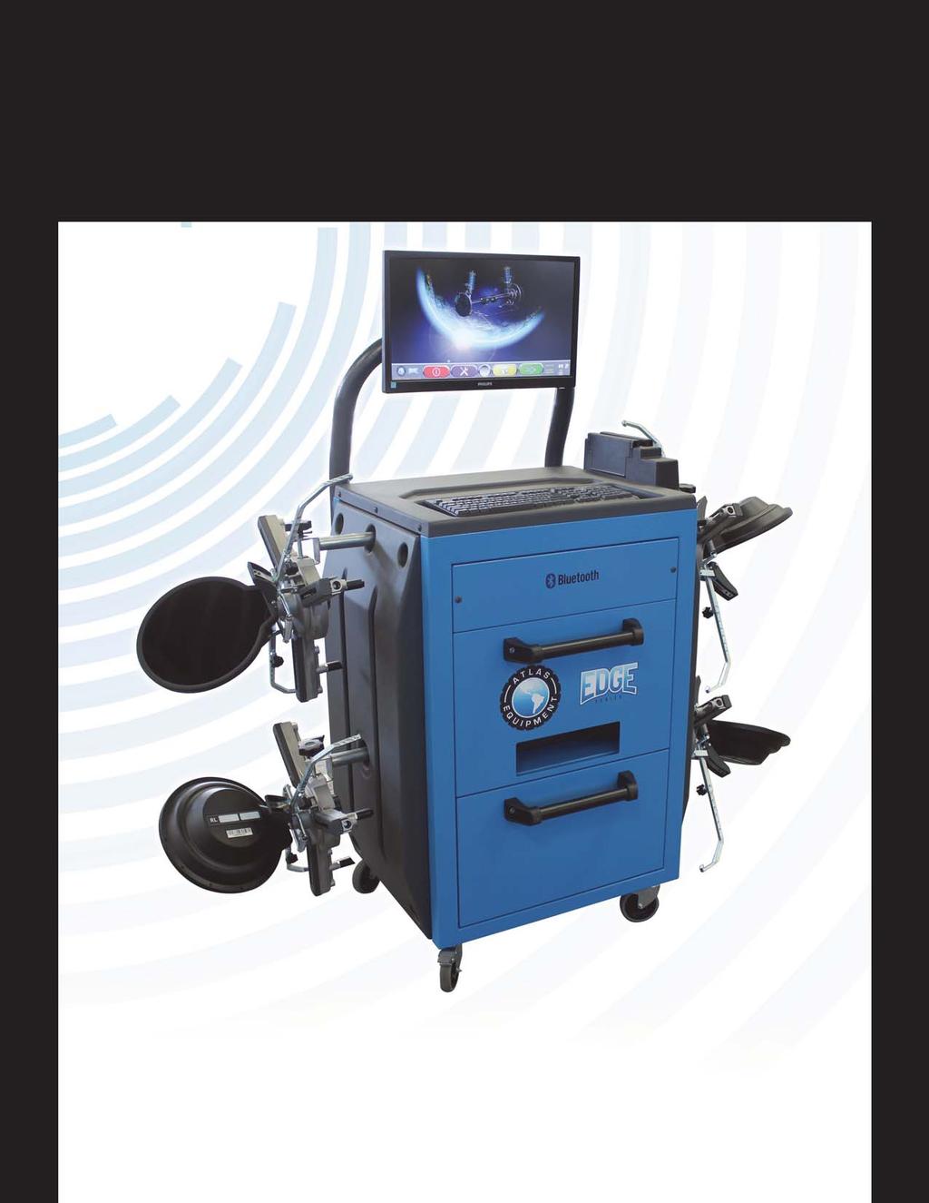
Atlas Edge Alignment Calibration Page 1
 Atlas Edge Alignment Calibration Page 1 ATLAS EDGE ALIGNMENT CALIBRATION GUIDE Figure A Before your calibration, Make sure you have all of the parts included in your Atlas Alignment Calibration Kit. See
Rack Installation Instructions
 Rack Installation Instructions Review the documentation that comes with your rack cabinet for safety and cabling information. When installing your server in a rack cabinet, consider the following: v Two
BMW KDS Wheel Alignment System
 OPERATION INSTRUCTIONS Form 5215T, 09-04 BMW KDS Wheel Alignment System WinAlign Program Version 8.0 Copyright 2004 Hunter Engineering Company Contents 1. Getting Started... 1 1.1 Introduction... 1 1.2
Further Information can be found at
 Below is a step by step guide to assembling the Hurricane-Rig. Remember that this is a precision optical instrument. Excessive force can bend critical parts. If treated well it should give many years of
Printing Your First Page. Attaching the Paper Support. Plugging in the Printer. Checking the Printer
 Printing Your First Page Attaching the Paper Support Checking the Printer Plugging in the Printer Installing the Ink Cartridges Installing the Printer Software Connecting the Printer 4011307 XXX-00 Attaching
Removal and Installation8
 8 Screw Types 8-4 Top Cover Assembly 8-5 Left Hand Cover 8-6 Right Hand Cover 8-10 Front Panel Assembly 8-14 Left Rear Cover 8-15 Right Rear Cover 8-16 Extension Cover (60" Model only) 8-17 Media Lever
English 1. Package Contents. The package contains the following items. In case there is any missing or damaged item, contact your dealer immediately.
 1. Package Contents The package contains the following items. In case there is any missing or damaged item, contact your dealer immediately. Car Recorder Bracket Quick Start Guide Car adapter 1 2. Product
KM-4800w. Installation Guide
 KM-4800w Installation Guide TABLE OF CONTENTS page 1 Installation Requirements 2 2 Unpacking 3 2. 1 Unpacking 3 2. 2 Confirmation of Accessories 5 3 Leveling the Machine 7 4 Setup of the Roll Deck 9 5
Installing the Printer Software
 4 Printing Your First Page Attaching the Paper Support 7 1 Checking the Printer 6 2 Plugging in the Printer 3 Installing the Ink Cartridges 5 Installing the Printer Software Connecting the Printer 4012581-00
Please read thoroughly before starting installation and check that kit contents are complete.
 Chrysler/Dodge/Jeep Remote Add-On CD player for RA1, RA2, RA3, or RA4 radios (Kit # 5000-8750) 2013-current RAM truck and Viper; 2015-current Charger, Challenger, and 300; 2017 Pacifica Please read thoroughly
Keyser Manufacturing Travel Indicator
 Keyser Manufacturing Travel Indicator Owner s Manual and Quick Reference Guide Table of Contents Disclaimer... 2 What s Included... 3 Travel Indicator Sensor Overview... 4 Recommendations for Installation...
* IMPORTANT * REGISTERING YOUR MACHINE
 * IMPORTANT * REGISTERING YOUR MACHINE Thank you for your purchase of the Keyline 994 Laser. Before continuing with machine setup and use, please complete the following; COMPLETE PRODUCT REGISTRATION FORM
Epson SureColor F6070 Setup Guide
 Epson SureColor F6070 Setup Guide 2 Unpacking and Assembling the Printer Read all of these instructions before using your printer. Also be sure to follow all warnings and instructions marked on the printer
Assembly and Set-Up Instructions
 HP DesignJet 500 and 800 Series Printers Assembly and Set-Up Instructions 1. Check the Contents of the Package This Assembly and Set-Up Poster Day-to-day package containing Using Your Printer documentation
INSTALLATION INSTRUCTIONS
 2015 F-150 8 MyTouch factory display 360º Vision System (Kit # AVMS-3618) DUE TO THE COMPLEXITY OF THIS KIT PROFESSIONAL INSTALLATION IS REQUIRED CALIBRATION KIT IS REQUIRED FOR FINAL PROGRAMMING -Must
Quick start guide for i5 520 ( or )
") Quick start guide for i5 520 (9405-520 or 9406-520) 1 Before you begin This Quick start guide contains an abbreviated set of setup instructions designed to help you quickly unpack and set up a standard
Quick start guide for i5 520 (9405-520 or 9406-520) 1 Before you begin This Quick start guide contains an abbreviated set of setup instructions designed to help you quickly unpack and set up a standard
TDM To MiniMech conversion ProceDure
 TDM To MiniMech conversion ProceDure (Model 9100 ATM) TDN 07102-00079 Apr 1 2009 CorporATe HeAdquArTers: 522 E. Railroad Street Long Beach, MS 39560 PHONE: (228) 868-1317 FAX: (228) 868-0437 COPYRIGHT
How To Install: C4000 EMV Upgrade Kit
 How To Install: C4000 EMV Upgrade Kit IMPORTANT: Before proceeding with installation please verify you have the current card reader bezel in the kit. Correct bezel will have a small eject pin hole below
Installation Instructions
 Installation Instructions Page 1 of 18 November 2007 Communication, Hands-Free Version 6.0 Accessory Development These Installation Instructions supersede all previous versions. SUBJECT PHONE DOCKING CRADLE
To connect the AC adapter:
 Replacing the AC Adapter Replacing the AC Adapter 3 Plug the power cord into a wall outlet. The power indicator turns on. To connect the AC adapter: Connect the power cord to the AC adapter. Power indicator
Xi4 Quick Reference Guide
 Xi4 Quick Reference Guide Use this guide to operate your printer on a daily basis. For more detailed information, refer to the User Guide. Printer Components Figure shows the components inside the media
Megatouch FORCE Monitor Chassis Board Replacement
 Megatouch FORCE Monitor Chassis Board Replacement Visit the Merit Industries, Inc. Web site http://www.meritind.com merit industries, inc. PM0337-01 Rev C Table of Contents FORCE Classic Monitor Chassis
Unpacking and Installing the Flora 2512 UV Printer. Steps 1: Unscrew the 10mm bolts holding the top. Then remove the top and put in a safe place.
 Unpacking and Installing the Flora 2512 UV Printer Steps 1: Unscrew the 10mm bolts holding the top. Then remove the top and put in a safe place. Step 2: Unscrew 10mm bolts holding the end panels. On the
Assembly and Setup Manual
 M-11 Series Copyboard/C-11 Series Captureboard Assembly and Setup Manual This is the installation and assembly manual for the M-11 series/c-11 series. To the Customer Specialized techniques are required
BD Laser User Guide * IMPORTANT * PLEASE READ THE FOLLOWING INSTRUCTIONS CAREFULLY AS IMPROPER USE MAY DAMAGE THE MACHINE AND VOID THE WARRANTY.
 BD Laser User Guide * IMPORTANT * PLEASE READ THE FOLLOWING INSTRUCTIONS CAREFULLY AS IMPROPER USE MAY DAMAGE THE MACHINE AND VOID THE WARRANTY. BD Laser arrives ready to use with jaws and cutters preinstalled.
Quick start guide for p5 520 ( )
") Quick start guide for p5 520 (9111-520) 1 Before you begin This Quick start guide contains an abbreviated set of setup instructions designed to help you quickly unpack and set up a standard system. Users
Quick start guide for p5 520 (9111-520) 1 Before you begin This Quick start guide contains an abbreviated set of setup instructions designed to help you quickly unpack and set up a standard system. Users
Instructions for installing your QuiltCam on your Gammill quilt machine.
 Instructions for installing your QuiltCam on your Gammill quilt machine. The items include with your QuiltCam Items included in all packages: QuiltCam Control Box, See Figure 1 Power Supply, Figure 2 Video
Rack Installation Instructions
 Rack Installation Instructions Review the documentation that comes with your rack cabinet for safety and cabling information. Before installing your server in a rack cabinet, review the following guidelines:
Dell Venue 11 Pro Bundle
 One Blue Hill Plaza, 16 th Floor, PO Box 1546 Pearl River, NY 10965 1-800-PC-AMERICA, 1-800-722-6374 (Voice) 845-920-0800 (Fax) 845-920-0880 Dell Venue 11 Pro Bundle This document provides step-by-step
M101M4 Tablet PC Quick Start Guide V1.0
 M101M4 Tablet PC Quick Start Guide V1.0 Please read these instructions carefully before using this product, and save this manual for future use. Getting Started Congratulations on purchasing this rugged
Additional Help For additional installation instructions and videos, please visit our website at What s Included
 Model 400, 40, 40 Additional Help For additional installation instructions and videos, please visit our website at www.current-usa.com What s Included Each LOOP Marine Bundle Kit includes: Item A B C D
Unpack the machine and its components. Cassette/Multi-purpose tray
 Set-Up Sheet Thank you for purchasing the Canon imageclass D320. To get your machine ready for use, please follow the instructions in this Set-Up Sheet before referring to any other documentation. Unpack
MBX INSTRUCTION MANUAL. Please read this manual carefully before using the MBX! Mid-range studio stand
 MBX Mid-range studio stand INSTRUCTION MANUAL EN Please read this manual carefully before using the MBX! CAMBO Thank you for purchasing a Cambo product. This new classed Mid-range studio stand will suit
INSTALLATION INSTRUCTIONS for the Kodak ADAPTIVE PICTURE EXCHANGE (APEX) 26, 48, 74, and 122
 26, 48, 74, and 122") {InstallationInstructs}{Production}{KodakServiceSupport}{None} Publication No. II3337-2 10FEB09 INSTALLATION INSTRUCTIONS for the Kodak ADAPTIVE PICTURE EXCHANGE (APEX) 26, 48, 74, and 122 Important Qualified
{InstallationInstructs}{Production}{KodakServiceSupport}{None} Publication No. II3337-2 10FEB09 INSTALLATION INSTRUCTIONS for the Kodak ADAPTIVE PICTURE EXCHANGE (APEX) 26, 48, 74, and 122 Important Qualified
UCIT LIVE HD 4 Camera DVR. Installation Manual. 10/17 Version 2.0
 UCIT LIVE HD 4 Camera DVR Installation Manual 10/17 Version 2.0 This is a step by step guide that will walk you through installing the UCIT LIVE HD 4 Channel Camera System. Basic wiring experience and
Rack Installation Instructions
 Rack Installation Instructions Review the documentation that comes with your rack cabinet for safety and cabling information. Before installing your server in a rack cabinet, review the following guidelines:
Macro View All in One Scope Description. 2. Features. 3. Package Contents
 Macro View All in One Scope 26700-104-00 1. Description Portable system ideal for inline use This self-contained video inspection system is a compact unit, that simplifies quality checks at any stage of
UCIT LIVE HD 4 Camera DVR. Installation Manual. 1/18 Version 1.0
 UCIT LIVE HD 4 Camera DVR Installation Manual 1/18 Version 1.0 This is a step by step guide that will walk you through installing the UCIT LIVE HD 4 Channel Camera System. Basic wiring experience and knowledge
IBM Systems. Quick start guide for IBM System p5 505 ( )
") IBM Systems Quick start guide for IBM System p5 505 (9115-505) 1 Before you begin This Quick start guide contains an abbreviated set of setup instructions designed to help you quickly unpack and set up
IBM Systems Quick start guide for IBM System p5 505 (9115-505) 1 Before you begin This Quick start guide contains an abbreviated set of setup instructions designed to help you quickly unpack and set up
Multi-Use Flip Desks.
 A S S E M B L Y i n s t r u c t i o n s Multi-Use Flip Desks How to install single and double ilid Multi-Use Flip Desks. Desks are shown modeled with keyboards, LCD monitors, mice and CPUs: these computer
Installing 6 Indexer: PRS Standard Tools
 888-680-4466 ShopBotTools.com Installing 6 Indexer: PRS Standard Tools Copyright 2016 ShopBot Tools, Inc. page 1 Copyright 2016 ShopBot Tools, Inc. page 2 Table of Contents Overview...5 Installing the
Soundbar Home Theater Speaker System with Bluetooth FAQ (NS-SB316) March 2016
 March 2016") Soundbar Home Theater Speaker System with Bluetooth FAQ (NS-SB316) March 2016 Setup... 2 Question 1: Where can I find mounting and setup instructions?... 2 Question 2: What tools and materials do I need
Soundbar Home Theater Speaker System with Bluetooth FAQ (NS-SB316) March 2016 Setup... 2 Question 1: Where can I find mounting and setup instructions?... 2 Question 2: What tools and materials do I need
The basic product comes with the IRS5 control board, 3 internal cables, 1 external cable with a 5 volt adapter and a mounting bracket with hardware.
 Please read these instructions and watch the Installation Video before you proceed with the installation of the PC-IRS5-01. Installation Video: http://youtu.be/os98e32vhb4 The PC-IRS5-01 Infrared Receiver
User's Guide. Video Borescope. Models BR200 and BR250
 User's Guide Video Borescope Models BR200 and BR250 Introduction Congratulations on your purchase of this Extech BR200 (17mm camera head) or BR250 (9mm camera head) Video Borescope. This instrument was
Thank you for purchasing a ZT-1300 printer! The following guide will help you install the equipment and software that goes with your ZT-1300 printer.
 Thank you for purchasing a ZT-1300 printer! The following guide will help you install the equipment and software that goes with your ZT-1300 printer. It is strongly recommended that you read through the
994 LASER QUICK GUIDE
 994 LASER Quick-Start Guide CONTENTS Machine set-up & password entry Jaw calibration Cut by code & decode How to replace the cutter & change the tracer Short form instructions Replacemente parts list IMPORTANT
Tactical Weather Station Set-Up Guide 1
 Tactical Weather Station Set-Up Guide 1 This is a generic overview of a portable WEATHERPAK 3 meter tripod set-up. Your system may not include all of the components listed, or may have different components.
Assembly and Setup Manual
 M-12 Series Copyboard / C-12 Series Captureboard Assembly and Setup Manual This is the installation and assembly manual for the M-12 series Copyboard and C-12 series Captureboard. (The copyboard and/or
CAVS USA Inc. Quick Start Manual For Karaoke Jukebox CAVS JB-99RX. Version and up
 Quick Start Manual For Karaoke Jukebox CAVS JB-99RX Version 1.0.0.261 and up 1 Contents Page 1. Unpacking 3 2. Installation 4 2.1 Touch Screen monitor 4 2.2 Mixer-Amplifier 5 2.3 Microphone 5 3. Booting
Start Here. 3 Set up your PictureMate Pal and print no computer required! 4. PictureMate Pal comes with all these items in the box.
 Start Here PM 00 Connect the power adapter to the back of. Connect the power cable to the power adapter. Set up your and print no computer required! Note: To print from your computer, see Plug In and Turn
Nov. 07, 2013 p. 5 - changed the B axis unit value to from Changed by Randy per Frank s request.
 Correction notes Nov. 07, 2013 p. 5 - changed the B axis unit value to 45.1389 from 40.0000. Changed by Randy per Frank s request. Jan. 22, 2018 p. 5 - changed the B axis unit value and corresponding picture
PoE/FPR Kit for Auto-Sync Time Clock. The Auto-Sync Time Clock is a validated time system with a Web interface and auto discovery.
 ASTCPOEK PoE/FPR Kit for Auto-Sync Time Clock The Auto-Sync Time Clock is a validated time system with a Web interface and auto discovery. The ASTCPOEK Kit provides Power over Ethernet with Full Power
trimble r10 GNSS System
 TRIMBLE R10 SERIES RECEIVER QUICK START GUIDE trimble r10 GNSS System C Warning: For safety information, refer to the Safety Information section of the Trimble R10 GNSS Receiver User Guide. Five simple
Setting up NCR Silver for ios. This guide will walk you through the initial set up of NCR Silver ios.
 Setting up NCR Silver for ios This guide will walk you through the initial set up of NCR Silver ios. V3 INTRODUCTION Welcome to NCR Silver! Use this document to set up your NCR Silver system. This document
Mounting on the Ceiling Using Flush Mount (Face Down)
") Mounting on the Ceiling Using Flush Mount (Face Down) Installation Guide 2014/02/14 Table of Contents Safety Information... 3 Installation Procedures... 5 Step 1: Drill a Hole on the Ceiling... 5 Step
Mounting on the Ceiling Using Flush Mount (Face Down) Installation Guide 2014/02/14 Table of Contents Safety Information... 3 Installation Procedures... 5 Step 1: Drill a Hole on the Ceiling... 5 Step
SKF Shaft Alignment Tool TKSA 31
 SKF Shaft Alignment Tool TKSA 31 SKF Maintenance Products April 2015 E&OE SKF Shaft Alignment Tool TKSA 31 The intuitive and affordable laser shaft alignment system. Slide 3 Introduction of the TKSA 31
1. Prerequisites 8 2. Prepare the Chemistrie TM lenses 9 3. Perform a Chemistrie TM job 10
 User manual USER MANUAL CONTENTS CONTENTS MR BLUE SUN & SPORT EDITION 5 I. PERFORM A CHEMISTRIE TM JOB 7 1. Prerequisites 8 2. Prepare the Chemistrie TM lenses 9 3. Perform a Chemistrie TM job 10 II. CARRY
NetCommWireless. Quick Start Guide NTC-30 Series - Outdoor WiFi Router
 NetCommWireless Quick Start Guide NTC-30 Series - Outdoor WiFi Router NetCommWireless Let s get this show on the road You must be excited to get started with your Outdoor WiFi Router. If all goes to plan,
User Guide. Video Borescope. Models BR200 and BR250
 User Guide Video Borescope Models BR200 and BR250 Introduction Congratulations on your purchase of this Extech BR200 (17mm camera head) or BR250 (9mm camera head) Video Borescope. This instrument was designed
Microline 420/421 & 490/491
 Check the contents: 1. Printer 2. Ribbon cartridge 3. Power Cable 4. CD with drivers and online User Guide 5. Setup Guide 2 1. 2. 1. Grasp tabs (1) and open access cover (2). 2. Remove printhead shipping
Easy 3D WLAN CCD kits for ML 1800 and ML TECH+ Wheel alignment with user PC
 Easy 3D WLAN CCD kits for ML 1800 and ML TECH+ Wheel alignment with user PC Wireless transfer to tablet PC Saving space without PC cabinet and fewer cables Flexible, mobile and highly accurate Easy 3D:
W205-N RVC NTV-KIT703
 3950 NW 120 th Ave, Coral Springs, FL 33065 TEL 561-955-9770 FAX 561-955-9760 www.nav-tv.com info@nav-tv.com W205-N RVC NTV-KIT703 Overview The W205-N RVC Kit interfaces a backup camera input (with active
Canon Powershot S200 Camera lens Replacement
 Canon Powershot S200 Camera lens Replacement This guide will walk you through the process of removing the camera's lens for replacement. Written By: Joseph Melo Page 1 of 16 INTRODUCTION The lens is used
EVOLVE1-M MONITOR ARM
 EVOLVE1-M MONITOR ARM EVOLVE1-M Rev A 2/17 Model EVOLVE1-M-SLV Model EVOLVE1-M-BLK Model EVOLVE1-M-WHT ASSEMBLY AND ADJUSTMENT EVOLVE1-M MONITOR ARM PARTS AND TOOLS PLEASE REVIEW these instructions before
The Cisco Wireless IP Phone 8821-EX has not been tested or certified with any accessories for use in Potentially Explosive Atmosphere.
 Supported, page 1 Headsets, page 1 Cisco Wireless IP Phone 8821 Desktop Charger, page 2 Cisco Wireless IP Phone 8821 Multicharger, page 6 Secure the Charger with a Cable Lock, page 10 Supported You can
DYNAVISION D2 TM INSTALLATION MANUAL
 DYNAVISION D2 TM INSTALLATION MANUAL Rev 12 Dynavision International 8800 Global Way, West Chester, Ohio 45069 USA EMAIL:info@dynavisiond2.com, WEBSITE: www.dynavisiond2.com, FAX: (905) 294-6327 Unpacking
Trimble R10 MODEL 2 GNSS SYSTEM. C WARNING For safety information, refer to the Safety Information FIVE SIMPLE STEPS TO GET STARTED
 QUICK START GUIDE Trimble R10 MODEL 2 GNSS SYSTEM C WARNING For safety information, refer to the Safety Information section of the Trimble R10 Model 2 GNSS Receiver User Guide. FIVE SIMPLE STEPS TO GET
Q2 XBee Handheld Controller Assembly Guide
 Q2 XBee Handheld Controller Assembly Guide Copyright Quantum Robotics Inc. Q2 Controller V1.0 1 Parts List: The kit comes with 14 individual bags. 1. Case Top and Bottom 2. Case Screw Package containing:
Ag Leader Technology Insight. Direct Command Installation Spra-Coupe 7000 Series
 Note: Indented items indicate parts included in an assembly listed above. Part Name / Description Part Number Quantity Direct Command Spra-Coupe 7000 Kit 4100531 1 Liquid Product Control Module 4000394
Sync KIT SYSTEM INSTALLATION
 2008 Navigator, Navigator L Sync Kit Manual Table of Contents Sync KIT SYSTEM INSTALLATION CONTENTS INSTALLATION Sync Kit GENERAL PROCEDURES Configuration & Programming Functional Test Troubleshooting
DIGITAL Server Rackmount Installation Guide
 DIGITAL Server Rackmount Installation Guide Part Number: ER-PCSRA-IA. E01 Digital Equipment Corporation December 1997 The information in this document is subject to change without notice and should not
ASSEMBLY AND ADJUSTMENT
 EDGE-WALL MONITOR ARM EDGE-WALL Rev A 2/17 Model EDGE-WALL-SLV ASSEMBLY AND ADJUSTMENT EDGE-WALL MONITOR ARM PLEASE REVIEW these instructions before beginning the installation. Check that all parts and
Digital Ink Pad+ User Manual
 Digital Ink Pad+ User Manual Page 1 Welcome. Dear user, thank you for purchasing this product. Much investment in time and effort has gone into its development, and it is our hope that it will give you
Nikon D610 Flash Capacitor Replacement
 Nikon D610 Flash Capacitor Replacement This guide will help to show you how to replace the D610's Flash Capacitor. Written By: Daniel Eagan ifixit CC BY-NC-SA www.ifixit.com Page 1 of 10 INTRODUCTION In
ImageScan Pro 800ix Series High-Speed ADF Scanner. Installation and Setup Guide. Installation and Setup Guide
 ImageScan Pro 800ix Series High-Speed ADF Scanner Installation and Setup Guide Installation and Setup Guide Box Contents: 1. Scanner 2. USB Cable 3. AC Adapter 4. Stacker Tray 5. Installation Guide 6.
Contents. Text Notations. Copyright. Using the digitizer pen (Optional) 10. Contents 3. Basic Items 4. Using the Slate PC Dock (Optional) 11
 10. Contents 3. Basic Items 4. Using the Slate PC Dock (Optional) 11") Contents Contents 3 Basic Items 4 Overview 5 Setting up the computer 8 Using the digitizer pen (Optional) 10 Using the Slate PC Dock (Optional) 11 Using the Bluetooth Wireless Keyboard (Optional) 14 Text
Contents Contents 3 Basic Items 4 Overview 5 Setting up the computer 8 Using the digitizer pen (Optional) 10 Using the Slate PC Dock (Optional) 11 Using the Bluetooth Wireless Keyboard (Optional) 14 Text
Removal and Installation 8
 Removal and Installation 8 8 Introduction 8-2 Service Calibration Guide to Removal and Installation 8-4 Window 8-8 Covers and Trims 8-12 Rear Tray 8-31 Rear Cover 8-32 Media Lever 8-33 Media Lever Position
1. Charging. 2. In-app Setup. 3. Physical Installation. 4. Features. 5. Troubleshooting
 Spotlight Cam Smart Security at Every Corner of Your Home Your new Spotlight Cam lets you extend the Ring of Security around your entire property. Now, you ll always be the first to know when someone s
ViZion DR + Wireless Install Guide
 1 ViZion DR + Wireless Install Guide 1. Open the DR panel box. 2. Put aside the three cables from the top layer of Styrofoam for storage. These cables are only required for potential troubleshooting scenarios.
Installation Manual for B8300 and Its Peripheral Devices
 Installation Manual for B8300 and Its Peripheral Devices Finishing device Duplex/bypass device Finishing device To install the devices efficiently, follow the procedure below. Some peripheral devices may
USER MANUAL PRUVEEO All Rights Reserved.
 PRUVEEO USER MANUAL 1 Warm Prompt We recommend that you carefully read this manual before using the dash cam, then read it again with the dash cam in your hands as this will help you to familiarize yourself
B&W RearView Camera Installation & Operation
 B&W RearView Camera Installation & Operation CA52 (Camera) FOR MORE INFORMATION WWW.STRATEGICVISTA.COM BEFORE OPERATING THIS SYSTEM, PLEASE READ THIS MANUAL THOROUGHLY AND RETAIN IT FOR FUTURE REFERENCE
Service Calibrations 5
 5 Service Calibrations 5-3 ing the Service Calibrations Menu 5-4 1. Scan-Axis Calibration 5-7 2. Service Station Calibration 5-11 3. Accuracy Calibration 5-14 Carriage Height Calibration 5-18 Calibration
SMM501/501-H (Surveillance Mode Module) Ford Police Interceptors (Sedan and SUV)
 Ford Police Interceptors (Sedan and SUV)") An ISO 9001:2008 Registered Company SMM501/501-H (Surveillance Mode Module) 2013-2014 Ford Police Interceptors (Sedan and SUV) Introduction The SMM501/501-H is intended for 2013 and 2014 Ford Police Interceptors
An ISO 9001:2008 Registered Company SMM501/501-H (Surveillance Mode Module) 2013-2014 Ford Police Interceptors (Sedan and SUV) Introduction The SMM501/501-H is intended for 2013 and 2014 Ford Police Interceptors
TABLE OF CONTENTS SECTION 1 TABLETOP CONFIGURATION SECTION 2 TABLETOP CONFIGURATION ACCESSORIES SECTION 3 SLIDE CONFIGURATION
 S6 USER S MANUAL TABLE OF CONTENTS SECTION 1 TABLETOP CONFIGURATION SECTION 2 TABLETOP CONFIGURATION ACCESSORIES SECTION 3 SLIDE CONFIGURATION SECTION 4 SLIDE CONFIGURATION ACCESSORIES SECTION 5 RACK MOUNT
Industry s First Alignment System with Bluetooth Wireless Communication. Sensor-mounted Keypads Provide Total On-vehicle Operation
 Industry s First Alignment System with Bluetooth Wireless Communication Sensor-mounted Keypads Provide Total On-vehicle Operation Patented 3-Point, Self-Centering, Zero Runout, No-Mar Wheel Clamps Kwik-Way
PORTA-JIB EXPLORER. Jib Arm details and assembly instructions
 Our lightest, most versatile Jib for camera systems with front weight of 22 lbs (10 kg.) or less. Canon 7D Camera with matte box, follow focus, external battery, Marshall monitor, balanced monitor bracket,
Mi Smartphone Gimbal Manual Please read the manual carefully before using the product.
 Mi Smartphone Gimbal Manual Please read the manual carefully before using the product. 1. Product Introduction Product accessories list USB charging cable x1 Mi Smartphone Gimbal Manual Please read the
Boxer HD-2X Motorized Pan Tilt Head (P-BXR-HD-2X)
") Boxer HD-2X Motorized Pan Tilt Head (P-BXR-HD-2X) I N STR UC TI ON MANUAL All rights reserved No part of this document may be reproduced, stored in a retrieval system, or transmitted by any form or by
Boxer HD-2X Motorized Pan Tilt Head (P-BXR-HD-2X) I N STR UC TI ON MANUAL All rights reserved No part of this document may be reproduced, stored in a retrieval system, or transmitted by any form or by
ARC-CDJPLAYER INSTALLATION MANUAL Full plug and play kit, universal fit for use in Chrysler vehicles with RA1, RA2, RA3, or RA4 radios.
 Required for Install: ARC-CDJPLAYER INSTALLATION MANUAL Full plug and play kit, universal fit for use in Chrysler vehicles with RA1, RA2, RA3, or RA4 radios. 1. Chrysler/Dodge/Jeep vehicle with Uconnect
CIB 3047 (14B) 10-Button Voice Terminal Fixed Desk Stand and Wall Mount (32007)
 10-Button Voice Terminal Fixed Desk Stand and Wall Mount (32007)") CIB 3047 (14B) 10-Button Voice Terminal Fixed Desk Stand and Wall Mount (32007) CIB 3047 Comcode 845-659-325 Issue 1 CIB 3047 (14B) 10-Button Voice Terminal Fixed Desk Stand and Wall Mount (32007) This
CIB 3047 (14B) 10-Button Voice Terminal Fixed Desk Stand and Wall Mount (32007) CIB 3047 Comcode 845-659-325 Issue 1 CIB 3047 (14B) 10-Button Voice Terminal Fixed Desk Stand and Wall Mount (32007) This
Arduino Panel Meter Clock. By Russ Hughes
 Arduino Panel Meter Clock By Russ Hughes (russ@owt.com) OVERVIEW My father has been a lifelong Ham Radio Operator with a fondness for almost anything with a panel meter. After seeing the Trinket Powered
guideweld LIVE Quick Start Guide
 guideweld LIVE Quick Start Guide Congratulations! The guideweld LIVE real welding guidance system is a live welding training and education tool that gives students instant feedback on core welding techniques
Installation & Setup Guide
 Installation & Setup Guide Contents Terminal Installation 3 Standby Status 3 Entry to Menus 4 Enrolment 5 Enrolment of Administrators 5 USB Data Download 5 Clearing Clocking Data 6 Setting the Terminal
Alignment. Featuring ProAlign. Software
 Alignment Featuring ProAlign Software HawkEye Alignment Featuring ProAlign Software The HawkEye Alignment System featuring ProAlign alignment software functions on a Linux operating system. This unique
Cloud Frame Quick Start Guide
 Cloud Frame Quick Start Guide The product's pictures and UI in this QSG are for reference only, and the product's appearance will vary with each model. Motion Sensor Remote illustration Open the battery
High Definition DVR. car audio & multimedia system. User Manual 12.1
 High Definition DVR User Manual Ver:12 12.1 Diagram on Buttons 1. MIC interface 2. TF slot 3. Knob 4. USB interface 5. GPS interface 6. AV interface 7. MIC indicator 8. Power indicator 9. REC indicator
8080 TBT 8060 TBT. Speedliner. Truck APPAREIL DE GEOMETRIE P.L. - V.U. COMMERCIAL VEHICLE ALIGNER ALINEADOR DE DIRECCION PARA CAMIONES F-E-GB
 Speedliner Truck 8080 TBT 8060 TBT APPAREIL DE GEOMETRIE P.L. - V.U. COMMERCIAL VEHICLE ALIGNER ALINEADOR DE DIRECCION PARA CAMIONES F-E-GB 8080TBT and 8060TBT represent the latest technology in truck