GRBL SHIELD FOR ARDUINO UNO USER MANUAL
|
|
|
- Tabitha Scott
- 6 years ago
- Views:
Transcription
1 GRBL SHIELD FOR ARDUINO UNO USER MANUAL YRCNC 2017


2 Introduction Thanks for supporting us! Hope you will have many hours of fun using this shield and that plenty hours of issueless cutting! The main features of the GRBL shield for Arduino UNO are: Opto isolated inputs for XYZ limits, probe, Start, Feed and EStop switches connected to the Arduino for improved noise suppression Buffered outputs for stepper drivers, coolant and spindle control LED indicators for XYZ limits as well as the probe input Proper regulated power for the Arduino and reverse connection protection Convenient terminals for simple and easy use of external and bigger stepper drivers The combination this shield + Arduino UNO yields a professional CNC controller which is worth much more Package Contents CNC Shield.. 1 piece 3mm LED s 4 pieces 2-way Header Pin connectors and associated HW.. 4 pieces 11mm Plastic spacers.. 4 pieces 16mm M3 Cap screws. 4 prices 2
3 Setting compatibility with GRBL version prior to 0.9j There are two jumpers at the bottom of the board JMP1 and JMP3 which are used to swap Z limit and PWM signals for GRBL versions prior to 0.9j If you are running a GRBL version later than 0.9i, the connections of JMP1 and JMP3 are already made. You can plug in and go! If for some reason running an earlier version prior to 0.9j and don t want to upgrade - cut the small connection on the PCB with a sharp knife, making sure you don t cut anything else. Then bridge the other pad with the centre pad by using solder or 0603 zero Ohm resistor. This needs to be done on both JMP1 and JMP3 see the images below: For GRBL prior to 0.9j cut the following tracks: and solder the following pads (or add zero Ohm 0603 resistor) 3
4 Setting Spindle Enable initial levels After power up there is a short period of time during which the Arduino UNO I/O pins are floating, at this moment the stepper drivers could be powered and some glitches may occur. To prevent this initial misbehaviour the board uses JMP2 to set the Spindle Enable (SP_EN) to high or low initial state. Ideally the initial Spindle Enable state should be non-active: For SP_EN active high the initial state of the line should be low For SP_EN active low the initial state of the line should be high By default, the jumper was pre-set for SP_EN with active state high. In case SP_EN active state on your machine is low cut the bridge on JMP2 and then bridge the other pad with the centre pad by using solder or 0603 zero Ohm resistor. See images below For SP_EN with active low state cut the following track: and solder the following pad (or add zero Ohm 0603 resistor) 4
 and the shorter is cathode (-) and ensure that the LED anode (+) is placed in the hole on PCB marked with (+) see image below: Alternatively the LED can be")
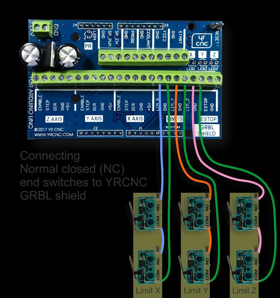
5 Mounting the XYZ limits and Probe LEDs The kit comes with four 3mm LED it s up to the user to decide how to mount them: The LED can be mounted directly on the board solder them by keeping in mind that the longer pin on the LED is anode (+) and the shorter is cathode (-) and ensure that the LED anode (+) is placed in the hole on PCB marked with (+) see image below: Alternatively the LED can be mounted on the panel of the machine in this case solder in the supplied header pins and then connecting the LED s via wire to the pins Mounting the shield over Arduino UNO board Please use the supplied spacers between the shield and the Arduino. This will ensure the PCB is not stressed when the screws are tightened. Also, one of the spacers have a flat part. This is for the holes that is close to pin SCL, close to the USB connector. Other than that, simply do as per any other electronic board installation! Connecting the XYZ limit switches There are two types of XYZ limit switches used in CNC machines normal opened (NO) and normal closed (NC). Normal opened switches are preferred because of the easier wiring but for more professional and robust designs is preferred the normal closed (NC) wiring. On the images below are shown how to connect the XYZ limit switches for NO and NC configurations. 5
6 6


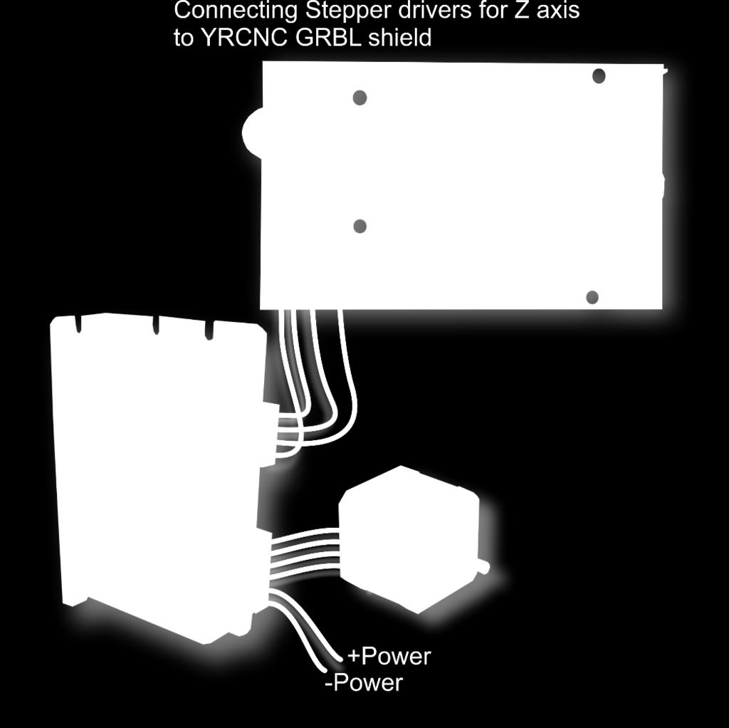
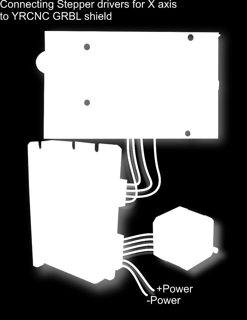
7 Connecting the stepper drivers The following pictures show how to connect two types of different stepper drivers to the GRBL shield: 7


8 8
9 Connecting other signals Probe, can either be NO or NC (Normally open or Normally closed) Spindle connection is made as indicated. SP_PWM is 0-5v, because of the Arduino voltage. Most PWN controller boards will only use GND and SP_PWM connections. The SP_EN is not used on these spindle PWM boards. Use if available, and refer to the JMP settings. Recommendations: Stepper drivers: TB6600 Stepper Driver (4A max) Controlling software (G Code Sender): bcnc Thanks to The GRBL developers They have given the community a wonderful product Luben Hristov Designer of the CNC Shield Ruben vd Merwe YRCNC and board manufacturer PS: Please review this shield on Thanks! 9
HUB-ee BMD-S Arduino Proto Shield V1.0
 HUB-ee BMD-S Arduino Proto Shield V1.0 User guide and assembly instructions Document Version 1.0 Introduction 2 Schematic 3 Quick user guide 4 Assembly 5 1) DIP Switches 5 2) Micro-MaTch Connector Headers
HUB-ee BMD-S Arduino Proto Shield V1.1
 HUB-ee BMD-S Arduino Proto Shield V1.1 User guide and assembly instructions Document Version 0.5 Introduction & Board Guide 2 Schematic 3 Quick User Guide 4 Assembly Guide 6 Kit Contents 7 1) Diodes and
TurboTaig Instruction Manual
 TurboTaig Instruction Manual Version: 2.2 Peter Homann 20 View St Highett 3190 homann@smartchat.net.au http://people.smartchat.net.au/~homann 1 Table of Contents Table of Contents... 2 Introduction...
Buildlog.net 4 Axis Stepper Driver Shield (p/n C16013 Rev 2) User Guide Rev 5
 User Guide Rev 5") Buildlog.net 4 Axis Stepper Driver Shield (p/n C16013 Rev 2) User Guide Rev 5 Safety & Disclaimers This stepper driver board is designed for experienced technicians only. The schematic should be studied
Buildlog.net 4 Axis Stepper Driver Shield (p/n C16013 Rev 2) User Guide Rev 5 Safety & Disclaimers This stepper driver board is designed for experienced technicians only. The schematic should be studied
Installation/assembly manual for DCC/Power shield
 Installation/assembly manual for DCC/Power shield The DCC circuit consists of the following components: R1/R6 R2/R3 R4/R5 D1 C2 2 kω resistor ½ Watt (colour code Red/Black/Black/Brown/Brown) 10 kω resistor
PP-BOB2-V1.0 PARALLEL PORT BREAKOUT BOARD
 PP-BOB2-v1 PARALLEL PORT BREAKOUT BOARD Document: Operation Manual Document #: T17 Document Rev: 2.0 Product: PP-BOB2-v1.0 Product Rev: 1.0 Created: March, 2013 Updated: Dec, 2014 THIS MANUAL CONTAINS
Phi-panel backpack assembly and keypad options Dr. John Liu 12/16/2012
 Phi-panel backpack assembly and keypad options Dr. John Liu 12/16/2012 1. Introduction:... 3 Currently available:... 3 2. Backpack assembly... 4 3. Connecting to a keypad... 6 4. Rotary encoder keypads...
High Power (15W + 15W) Stereo Amplifier
 Stereo Amplifier") High Power (15W + 15W) Stereo Amplifier Build Instructions Issue 1.0 Build Instructions Before you put any components in the board or pick up the soldering iron, just take a look at the Printed Circuit
High Power (15W + 15W) Stereo Amplifier Build Instructions Issue 1.0 Build Instructions Before you put any components in the board or pick up the soldering iron, just take a look at the Printed Circuit
Touch Sense Controller
 Touch Sense Controller Paul Boston May 11, 2011 (Modified May 22, 2014) (Modified Dec 28, 2015) The Touch Sense Controller is a microprocessor-controlled circuit designed to provide a switch closure when
UF-3701 Power Board Construction Guide
 Page 1/5 Soldering and Part Placement See the Chapter 3 of the MIT 6270 Manual for information on electronic assembly, including soldering techniques and component mounting. Construction Information All
How-To #7: Assemble an H-bridge Circuit Board
 How-To #7: Assemble an H-bridge Circuit Board Making a DC motor turn is relatively easy: simply connect the motor's terminals to a power supply. But what if the motor is to be controlled by an Arduino,
AXE Stack 18. BASIC-Programmable Microcontroller Kit. An inexpensive introduction to microcontroller technology for all ability levels
 Ltd AXE Stack 18 BASIC-Programmable Microcontroller Kit a division of An inexpensive introduction to microcontroller technology for all ability levels Free Windows interface software Programmable in BASIC
UNIPORT V2. Uniport V2
 UNIPORT V2 Uniport V2 USB powered Parallel port interconnection board with optical isolated inputs, buffered outputs, charge pump interlock and power relays Specification Full optical isolation of all
HDBB Breakout board user s manual
 HDBB Breakout board user s manual The HDBB breakout board was designed to use with our Whale2(-T)*, Whale3, Mammut* and Dugong servo drives or with any other third party stepper or servo drives which using
Manual. Model#-DB25M-3R6A. 6 Axis CNC Interface Breakout Board. Lastest update : Feb Store this manual away for further reference.
 Manual 6 Axis CNC Interface Breakout Board Model#-DB25M-3R6A Lastest update : Feb 2016 Read this manual carefully before making connections to the board. Store this manual away for further reference. Safety
Assembly Guide. LEDs. With these assembly instructions, you can easily build your own SWT16. All required components are included in this kit.
 Assembly Guide With these assembly instructions, you can easily build your own SWT16. All required components are included in this kit. You need the following tools: soldering iron, wire cutter and solder.
Arduino Uno. Arduino Uno R3 Front. Arduino Uno R2 Front
 Arduino Uno Arduino Uno R3 Front Arduino Uno R2 Front Arduino Uno SMD Arduino Uno R3 Back Arduino Uno Front Arduino Uno Back Overview The Arduino Uno is a microcontroller board based on the ATmega328 (datasheet).
MAIN PCB (The small one)
") THANKS FOR CHOOSING ONE OF OUR KITS! This manual has been written taking into account the common issues that we often find people experience in our workshops. The order in which the components are placed
THANKS FOR CHOOSING ONE OF OUR KITS! This manual has been written taking into account the common issues that we often find people experience in our workshops. The order in which the components are placed
KK1L 2x6 Antenna Switch Relay Controller / Dual Band Decoder Basic Assembly Version 4.8 (new 24-Aug-2009) Parts List updated 19-AUG-2016
 Parts List updated 19-AUG-2016") KK1L 2x6 Antenna Switch Relay Controller / Dual Band Decoder Basic Assembly Version 4.8 (new 24-Aug-2009) Parts List updated 19-AUG-2016 Ronald Rossi, KK1L http://home.comcast.net/~kk1l Design Features:
KK1L 2x6 Antenna Switch Relay Controller / Dual Band Decoder Basic Assembly Version 4.8 (new 24-Aug-2009) Parts List updated 19-AUG-2016 Ronald Rossi, KK1L http://home.comcast.net/~kk1l Design Features:
ARDUINO MEGA 2560 REV3 Code: A000067
 ARDUINO MEGA 2560 REV3 Code: A000067 The MEGA 2560 is designed for more complex projects. With 54 digital I/O pins, 16 analog inputs and a larger space for your sketch it is the recommended board for 3D
CP5176 Assembly guide. Soldering. CP5176 Assembly guide Main PCB PCB split. Document revision 2.1 Last modification : 12/11/17
 CP5176 Assembly guide Safety warning The kits are main powered and use potentially lethal voltages. Under no circumstance should someone undertake the realisation of a kit unless he has full knowledge
Makeblock Constructor I 3D Printer Kit. 2. 3D Printer Wiring Guide
 2. 3D Printer Wiring Guide 1 Content 2.1. Parts Required... 3 2.2 preparation... 7 2.2.1 Add heat sinks on the top of stepper motor driver chip... 7 2.2.2 Plug the jumper cap into corresponding position...
BLUETOOTH AMPLIFIER KIT
 PRODUCT INFORMATION BUILD INSTRUCTIONS CHECKING YOUR PCB & FAULT-FINDING MECHANICAL DETAILS HOW THE KIT WORKS CREATE YOUR OWN WIRELESS SPEAKER WITH THIS BLUETOOTH AMPLIFIER KIT Version 1.2 Index of Sheets
Insert the male, 90 angled, 2x10 connectors into the corresponding 2x10 sockets and put them in place, flat under the PCB. Solder.
 MC624 Assembly guide Safety warning The kits are main powered and use potentially lethal voltages. Under no circumstance should someone undertake the realisation of a kit unless he has full knowledge about
Manual 5 Axis CNC Interface Breakout Board Model#-DB25-1R5AM
 Manual 5 Axis CNC Interface Breakout Board Read this manual carefully before making connections to the board. Store this manual away for further reference. Safety Notes: The electronics of the control
The Basic Counter. Hobby Electronics Soldering Kit. Instruction Guide
 The Basic Counter Hobby Electronics Soldering Kit Instruction Guide TM For the best outcome, follow each step in order. We recommend reading this guide entirely before you get started. Tools required:
Shack Clock kit. U3S Rev 2 PCB 1. Introduction
 Shack Clock kit U3S Rev 2 PCB 1. Introduction Thank you for purchasing the QRP Labs Shack Clock kit. This clock uses the Ultimate3S QRSS/WSPR kit hardware, but a different firmware version. It can be used
PP-BOB2-V2.0 PARALLEL PORT BREAKOUT BOARD
 PP-BOB2-V2 PARALLEL PORT BREAKOUT BOARD Document: Operation Manual Document #: T18 Document Rev: 1.0 Product: PP-BOB2-V2.0 Product Rev: 1.0 Created: October, 2015 THIS MANUAL CONTAINS INFORMATION FOR INSTALLING
Pi PoE Switch HAT Quick Start And FAQ. Getting started. Kit contents
 Pi PoE Switch HAT Quick Start And FAQ Getting started The Pi PoE Switch HAT is an add on board for the Raspberry Pi that brings the Switch technology together with PoE all in one fantastic package! You
GUIDE TO SP STARTER SHIELD (V3.0)
") OVERVIEW: The SP Starter shield provides a complete learning platform for beginners and newbies. The board is equipped with loads of sensors and components like relays, user button, LED, IR Remote and
OVERVIEW: The SP Starter shield provides a complete learning platform for beginners and newbies. The board is equipped with loads of sensors and components like relays, user button, LED, IR Remote and
Necessary software and hardware:
 Necessary software and hardware: Bases: First, remember that I m a French guy so my English is not perfect ;) If you see any mistakes, don t hesitate to tell me so I can correct them (my email is at the
ARDUINO MEGA ADK REV3 Code: A000069
 ARDUINO MEGA ADK REV3 Code: A000069 OVERVIEW The Arduino MEGA ADK is a microcontroller board based on the ATmega2560. It has a USB host interface to connect with Android based phones, based on the MAX3421e
Breakoutboard Rev.2 for Estlcam
 Breakoutboard Rev.2 for Estlcam 1 Stefan Gemeinert,Frühlingstrasse 8 85253 Erdweg Operation Manual All rights to these operating instructions remain with cnc-technics. Texts, information and illustrations
Connecting PLH3D-6W Laser Heads to Openbuilds Acro-System: Getting Started Guide
 Connecting PLH3D-6W Laser Heads to Openbuilds Acro-System: Getting Started Guide Table of Contents 1. Attaching the Laser Head to the X-Y CNC... 2 2. Connecting the Electronics... 5 3. Installation and
Sega MegaDrive 1 RGB Bypass Installation Guide Rev 1.4
 Sega MegaDrive 1 RGB Bypass Installation Guide Rev 1.4 Revision 1 Board See Page 3 for important information Revision 2 Board Onboard 2k2 Pull up Resistor for CSYNC This step by step guide describes the
Cherub Chorus. Wobbly fun based on Rick Holt s Little Angel
 Cherub Chorus Wobbly fun based on Rick Holt s Little Angel Contents of this document are 2015 Pedal Parts Ltd. No reproduction permitted without the express written permission of Pedal Parts Ltd. All rights
Manual Version March 2007
 Manual Version 1.1 - March 2007 Page 1 Table of Contents Section1: 6922 Line Board Build... 3 6922 Line Board Version Notes... 5 6922 Line Board Build - HARD-WIRED VERSION... 5 Final Connections and Checks
Ultimate LPF kit: Relay-switched LPF kit
 Ultimate LPF kit: Relay-switched LPF kit PCB Revision 4 1. Introduction Thank you for purchasing the QRP Labs relay-switched low-pass filter (LPF) kit. This kit is designed to complement the Ultimate3
Light & Sound Control Module
 Light & Sound Control Module Operation and Installation Manual G-Scale Graphics 5860 Crooked Stick Dr. Windsor, CO 80550 970-581-3567 GScaleGraphics@comcast.net www.gscalegraphics.net Revision 55: C: Updated
Assembly of the TACOS WAT-910BD Housing v2
 1) Circuit Diagram 2) Assembly of PCB a)tools Required. Only simple hand tools are necessary to complete the assembly of the PCB. - Soldering Iron and solder - Needle nose pliers - Wire clippers/trimmers
Post Tenebras Lab. Written By: Post Tenebras Lab
 Post Tenebras Lab PTL-ino is an Arduino comptaible board, made entirely out of through-hole components. It is a perfect project to learn how to solder and start getting into the world of micro controllers.
DDS Unit Construction Guide of TJ6A pro
 DDS Unit Construction Guide of TJ6A pro The main board, PA and the DDS function of TJ6A pro is the same with TJ6A. The different part is the DDS unit in which the S meter unit (SM unit) is add (see picture
solutions for teaching and learning
 RKP18Motor Component List and Instructions PCB layout Constructed PCB Schematic Diagram RKP18Motor Project PCB Page 1 Description The RKP18Motor project PCB has been designed to use PIC microcontrollers
Profi4 Main Board Manual
 Profi4 Main Board Manual A. Scope of application It is used to run the signal processing of the host computer ( LPT port ), with MACH 3 CNC system software, and the peripheral machine dynamic electrical.
RC Tractor Guy Controller V2.1 Assembly Guide
 RC Tractor Guy Controller V. Assembly Guide Features 0 Push button inputs Dual axis thumb sticks with built-in push button Rotary encoders with built-in push button MCU Socket to suit Meduino Mega 560
Wii Nunchuk Transceiver. Wiring Diagrams
 Wii Nunchuk Transceiver Wiring Diagrams Wii Nunchuk Controller Wiring SCL SCL SDA +3v3 +3v3 Det SDA To Nunchuk Controller Top View Bottom View Bottom View 2.4GHz Wireless Transceiver CMD RXD TXD VCC 220Ω
Button Code Kit. Assembly Instructions and User Guide. Single Button Code Entry System
 Button Code Kit Single Button Code Entry System Assembly Instructions and User Guide Rev 1.0 December 2009 www.alan-parekh.com Copyright 2009 Alan Electronic Projects Inc. 1. Introduction... 4 1.1 Concept
Transcendent Frequency Counter
 Transcendent Frequency Counter with blue 2 x 16 LCD display This manual will guide you how to assemble, test and operate this frequency counter KIT. Features: The transcendent counter has two input channels
I2CMux Grove Board 0057-GRV4I2CMux-DSBT/ SF
 Features and Benefits: The is an easy to use 4 Channel I2C Multiplexer. The I2C Mux Breakout Board is a quad bidirectional translating switch controlled via the I2C bus. The SCL/SDA controlling fans out
Wind Logger Shield. Parts included: Date: 29/07/14 Version: 1.0 By: Matt Little
 Wind Logger Shield Date: 29/07/14 Version: 1.0 By: Matt Little Parts included: This is a simple shield to easily implement a wind resource data logging system. It is designed to read 2 x pulse type anemometers
Arduino ADK Rev.3 Board A000069
 Arduino ADK Rev.3 Board A000069 Overview The Arduino ADK is a microcontroller board based on the ATmega2560 (datasheet). It has a USB host interface to connect with Android based phones, based on the MAX3421e
Conect 121 Upgrade. Copyright 2013 Conqueror Design and Engineering Ltd.
 All rights reserved. Any dispute about the use of this software and/or hardware or of these terms and conditions shall be resolved or arbitrated under English Law. Manuals and accompanying documentation
You need the following components to assemble the Black n Wood Nixie Clock circuit board:
 You need the following components to assemble the Black n Wood Nixie Clock circuit board: Quantity Designator Description 1 Battery Battery, CR1220 1 Battery Battery holder 3 Button 1, Button 2, Button
Butterfly Laser Diode Mount
 LM14S2 Butterfly Laser Diode Mount Operating Manual LM14S2 Laser On TEC Driver LD Driver THORLABS, Inc. Ph: (973) 579-7227 435 Route 206N Fax: (973) 383-8406 Newton, NJ 07860 USA www.thorlabs.com 10614-D02
Grove Lightning Detector 0219-MOD1016G-01
 Features and Benefits: The is an Arduino and Raspberry Pi Grove compatible breakout board with a full set of connectors. No external antennas required! It is designed for use in Low Power applications
XNUCLEO-F030R8, Improved STM32 NUCLEO Board
 XNUCLEO-F030R8, Improved STM32 NUCLEO Board STM32 Development Board, Supports Arduino, Compatible with NUCLEO-F030R8 XNUCLEO-F030R8 Features Compatible with NUCLEO-F030R8, onboard Cortex-M0 microcontroller
Arduino Panel Meter Clock. By Russ Hughes
 Arduino Panel Meter Clock By Russ Hughes (russ@owt.com) OVERVIEW My father has been a lifelong Ham Radio Operator with a fondness for almost anything with a panel meter. After seeing the Trinket Powered
GAPuino User s Manual
 GAPuino User s Manual Greenwaves Technolgies Version 1.2 Contents 1 Introduction 2 2 2 3 Configuration 5 3.1 Jumper J3......................................... 5 3.2 Resistors..........................................
Ca Bling! Pacificon 2011 Norcal Buildathon Project
 Ca Bling! Pacificon 2011 Norcal Buildathon Project 10/23/2011 ver 1.1 by W1REX / QRPme www.qrpme.com The Ca Bling! Kit is a small Picaxe micro controller development board designed by W1REX as a project
AT42QT101X Capacitive Touch Breakout Hookup Guide
 Page 1 of 10 AT42QT101X Capacitive Touch Breakout Hookup Guide Introduction If you need to add user input without using a button, then a capacitive touch interface might be the answer. The AT42QT1010 and
Colecovision 5v Memory Mod Installation
 Colecovision 5v Memory Mod Installation The Colecovision suffers from common failure points: the power supply, power switch, and 4116 DRAM. The power supply suffers from poor soldering, the power switch
Hauptwerk Hardware 2016
 Hauptwerk Hardware Interface Board for the Universal Midi Encoder User Manual Page 1 Release 1.2 February 2016 Table of Contents Introduction...3 Board Overview...4 IMPORTANT PLEASE READ...5 Mounting...6
Zero2Go. User Manual (revision 1.03) Wide Input Range Power Supply for Your Raspberry Pi. Copyright 2017 UUGear s.r.o. All rights reserved.
 Wide Input Range Power Supply for Your Raspberry Pi. Copyright 2017 UUGear s.r.o. All rights reserved.") Zero2Go Wide Input Range Power Supply for Your Raspberry Pi User Manual (revision 1.03) Copyright 2017 UUGear s.r.o. All rights reserved. Table of Content Product Overview... 1 Product Details... 3 Package
Zero2Go Wide Input Range Power Supply for Your Raspberry Pi User Manual (revision 1.03) Copyright 2017 UUGear s.r.o. All rights reserved. Table of Content Product Overview... 1 Product Details... 3 Package
SharpSky Focuser Construction. SharpSky Focuser. Construction Document V st December 2012 Dave Trewren 1
 SharpSky Focuser Construction Document V0.12 1st December 2012 Dave Trewren 1 Contents 1 General... 3 1.1 Change Record... 3 1.2 References... 3 2 Introduction... 5 3 SharpSky driver installation... 5
Phi-connect for Arduino (connector board V1.9)
") Phi-connect for Arduino (connector board V1.9) Last reviewed on 3/29/2012 John Liu 1. Introduction... 2 2. Main features... 2 3. Parts list... 3 4. How to use... 4 5. Improving your Arduino experience
Phi-connect for Arduino (connector board V1.9) Last reviewed on 3/29/2012 John Liu 1. Introduction... 2 2. Main features... 2 3. Parts list... 3 4. How to use... 4 5. Improving your Arduino experience
3. The circuit is composed of 1 set of Relay circuit.
 Part Number : Product Name : FK-FA1420 ONE CHANNEL 12V RELAY MODULE This is the experimental module for a relay controller as the fundamental controlling programming. It is adaptable or is able to upgrade
TB6600 Stepper Motor Driver
 TB6600 Stepper Motor Driver V1.0 07 2018 Open Source Mechatronics LTD 2018 Safety Statement The author of this document is not liable or responsible for any accidents, injuries, equipment damage, property
IQ32 Upgrade Kit Assembly Instructions
 IQ32 Upgrade Kit Assembly Instructions Jim Veatch WA2EUJ September 17, 2018 TABLE OF CONTENTS 1. INTRODUCTION... 3 2. IQ-32 UPGRADE KIT INVENTORY... 4 3. PREPARING THE RS-HFIQ AND SIDE PANELS... 6 4. CONNECTING
BuffaloLabs WiFi Lantern Assembly guide version 1
 BuffaloLabs WiFi Lantern Assembly guide version 1 Needed equipment: Solder iron Solder wire Cutter Wire stripper (optional) Hot glue gun Overview of the components (not including USB cable and box panels)
AT42QT1010 Capacitive Touch Breakout Hookup Guide
 Page 1 of 7 AT42QT1010 Capacitive Touch Breakout Hookup Guide Introduction If you need to add user input without using a button, then a capacitive touch interface might be the answer. The AT42QT1010 Capacitive
IOX-16 User s Manual. Version 1.00 April Overview
 UM Unified Microsystems IOX-16 User s Manual Version 1.00 April 2013 Overview The IOX-16 Arduino compatible shield is an easy way to add 16 additional digital Input/Output (I/O) lines to your Arduino system.
MP3 audio amplifier. Build Instructions. Issue 2.0
 MP3 audio amplifier Build Instructions Issue 2.0 Build Instructions Before you put any components in the board or pick up the soldering iron, just take a look at the Printed Circuit Board (PCB). The components
Thunder Board 0240-THNDRBRD-DSBT
 ! Product Specification Features and Benefits: The is an Arduino and Raspberry Pi Grove compatible breakout board with a full set of connectors. No external antennas required! It is designed for use in
KDS Channel DMX Controlled Servo Kit
 KDS00801 8-Channel DMX Controlled Servo Kit This is a DMX512-A controlled servo kit using ANSI approved RJ-45 connectors for DMX networks. Power requirements are 8-20 VDC @ 50 ma. The board features an
Sierra Radio Systems. HamStack. Project Board Reference Manual V1.0
 Sierra Radio Systems HamStack Project Board Reference Manual V1.0 Welcome HamStack Project Board Reference Manual Revision 1.0.3 2011 George Zafiropoulos, KJ6VU and John Best, KJ6K This guide provides
Phi -1 shield Documentation. Table of content
 Phi -1 shield Documentation Last reviewed on 01/03/11 John Liu Table of content 1. Introduction: 2 2. List of functions: 2 3. List of possible projects: 2 4. Parts list: 3 5. Shield pin usage: 3 6. List
E3 CNC Router Troubleshooting Guide
 Simple Cost Effective Designs. E3 CNC Router Troubleshooting Guide The purpose of this document is to give those new to CNC routing is a quick reference for the common issues of getting the E3 CNC router
SK18A. 18 Pins PIC START-UP KIT. User s Manual V1.1. Dec 2007
 SK18A 18 Pins PIC START-UP KIT User s Manual V1.1 Dec 2007 Information contained in this publication regarding device applications and the like is intended through suggestion only and may be superseded
Building the VMW Time Circuitry Meter by Vincent M. Weaver 6 May 2014
 Building the VMW Time Circuitry Meter http://www.deater.net/weave/vmwprod/hardware/time_circuit/ by Vincent M. Weaver 6 May 2014 1 Introduction This is a work in progress. I will update it as I complete
CPU5A Economy Series USBCNC software included. Features
 CPU5A Economy Series 125 KHz step frequency, 4 axes. Card size 100x100mm. USB 2.0 connection. 100 Mbit Ethernet connection (*). 5 Status LED's. Full 4 axes interpolation (*). 7 Standard CNC outputs. 0-10V
Micro USB Lamp Kit ESSENTIAL INFORMATION. Version 2.0 DESIGN A STYLISH LAMP WITH THIS
 ESSENTIAL INFORMATION BUILD INSTRUCTIONS CHECKING YOUR PCB & FAULT-FINDING MECHANICAL DETAILS HOW THE KIT WORKS DESIGN A STYLISH LAMP WITH THIS Micro USB Lamp Kit Version 2.0 Build Instructions Before
AK-DS2482S-100. Reference manual. Copyright 2016 Artekit Italy All rights reserved
 AK-DS2482S-100 Reference manual Copyright 2016 Artekit Italy All rights reserved Contents About this document... 3 Revision history... 3 Contact information... 3 Life support policy... 3 Copyright information...
4X4 Driver Shield Manual
 3/31/2012 4X4 Driver Shield Manual High current, high side switching for Arduino Logos Electromechanical 4X4 Driver Shield Manual High current, high side switching for Arduino Introduction The Logos Electromechanical
The Bluetooth Controlled Relay Board & Speech Recognition Sets
 The Bluetooth Controlled Relay Board & Speech Recognition Sets Brought to you by: ENGINEERINGSHOCK ELECTRONICS Bluetooth Speech Module Features: 1) 10x Controllable Outputs 2) LCD Display 3) Arduino Compatible
EQ573 Assembly guide. EQ573 Assembly guide Main board 1. Diodes. 2. Resistors (1) 3. Test pins. 4. Ceramic capacitors.
 3. Test pins. 4. Ceramic capacitors.") EQ573 Assembly guide Safety warning The kits are main powered and use potentially lethal voltages. Under no circumstance should someone undertake the realisation of a kit unless he has full knowledge about
EQ573 Assembly guide Safety warning The kits are main powered and use potentially lethal voltages. Under no circumstance should someone undertake the realisation of a kit unless he has full knowledge about
Shack Clock kit PCB Revision: QCU Rev 1 or QCU Rev 3
 1. Introduction Shack Clock kit PCB Revision: QCU Rev 1 or QCU Rev 3 Thank you for purchasing this QRP Labs Shack Clock kit. The kit uses the same PCB and bag of components as some other QRP Labs kits.
Last Updated May 11, Electronics and Robotics LLC. ootbrobotics.com
 µpad Proto Base Assembly Guide Last Updated May 11, 2015 Table of Contents Required Tools... 5 Recommended Tools... 5 Assembly Procedure... 6 Step 1: Break Pin Headers to Size... 6 Table 1: Header Cut
Make your own secret locking mechanism to keep unwanted guests out of your space!
 KNOCK LOCK Make your own secret locking mechanism to keep unwanted guests out of your space! Discover : input with a piezo, writing your own functions Time : 1 hour Level : Builds on projects : 1,,3,4,5
One Grove Base Shield board this allows you to connect various Grove units (below) to your Seeeduino board; Nine Grove Grove units, consisting of:
 to your Seeeduino board; Nine Grove Grove units, consisting of:") GROVE - Starter Kit V1.0b Introduction The Grove system is a modular, safe and easy to use group of items that allow you to minimise the effort required to get started with microcontroller-based experimentation
GROVE - Starter Kit V1.0b Introduction The Grove system is a modular, safe and easy to use group of items that allow you to minimise the effort required to get started with microcontroller-based experimentation
UNIVERSAL MOTION INTERFACE (UMI) ACCESSORY
 ACCESSORY") USER GUIDE UNIVERSAL MOTION INTERFACE (UMI) ACCESSORY Introduction This user guide describes how to use the UMI-A, UMI-Flex, and UMI-Flex accessories. The UMI products are connectivity accessories you
USER GUIDE UNIVERSAL MOTION INTERFACE (UMI) ACCESSORY Introduction This user guide describes how to use the UMI-A, UMI-Flex, and UMI-Flex accessories. The UMI products are connectivity accessories you
CAN Switch Board (CSB)
") CAN Switch Board (CSB) The Cosworth CSB is a fully customised CAN Switch Board designed to be light and compact enough to fit onto a steering wheel. The CSB allows complicated steering wheel and connector
CAN Switch Board (CSB) The Cosworth CSB is a fully customised CAN Switch Board designed to be light and compact enough to fit onto a steering wheel. The CSB allows complicated steering wheel and connector
Rover 5. Explorer kit
 Rover 5 Explorer kit The explorer kit provides the perfect interface between your Rover 5 chassis and your micro-controller with all the hardware you need so you can start programming right away. PCB Features:
BalloonSat Sensor Array
 BalloonSat Sensor Array The PICAXE-08M2 in the BalloonSat flight computer is a digital device. Being digital, it functions best with a series of on and off voltages and does not interact very well with
C3 INDEX PULSE BOARD Rev. 6
 C3 INDEX PULSE BOARD Rev. 6 User manual Rev. 1 Fig. 1. C3 Index Pulse Board 1. Overview. This card provides easy way of capturing the pulse signal from photo-transistor and transmitting it to the parallel
Educato. Assembly Instructions
 Product Description The Educato is an Arduino compatible board that has about the functionality of the Arduino Uno. It also has the ability, however, to plug into a solderless breadboard and to have all
Digital Pins and Constants
 Lesson Lesson : Digital Pins and Constants Digital Pins and Constants The Big Idea: This lesson is the first step toward learning to connect the Arduino to its surrounding world. You will connect lights
The ICU-Duino Arduino Shield!
 The ICU-Duino Arduino Shield! Brought to you by: ENGINEERINGSHOCK ELECTRONICS FEATURES: On Board PIR (Passive Infra-red) Motion Sensor Red Indicator LED Infra-red (IR) Sensor Large Prototyping Area with
Storage Card Interface Kit
 Storage Card Interface Kit for MultiMediaCards(MMC) and Secure Digital Cards (SD) MMSD3K The MMSD3K is complete development kit interfaced to a SD or MMC card. This board ideal for projects that involve
Web Site: Forums: forums.parallax.com Sales: Technical:
 Web Site: www.parallax.com Forums: forums.parallax.com Sales: sales@parallax.com Technical: support@parallax.com Office: (916) 624-8333 Fax: (916) 624-8003 Sales: (888) 512-1024 Tech Support: (888) 997-8267
Manual Main PCB Small-MIDI 4
 Index PARTLIST MAIN PCB... 2 INTRODUCTION... 3 GENERAL... 3 THE CIRCUIT... 3 ASSEMBLY KIT... 4 ASSEMBLY OF THE PCB... 4 An important tip...... 4 ASSEMBLY... 4 THE CONNECTORS... 4 Power supply J1... 4 IDC