PIXMA MP830 SERVICE MANUAL
|
|
|
- Vincent Casey
- 6 years ago
- Views:
Transcription
1 PIXMA MP830 SERVICE MANUAL Revision 0 QY8-3AN-000 COPYRIGHT 2006 CANON INC. CANON PIXMA MP XX Scope This manual has been issued by Canon Inc., to provide the service technicians of this product with the information necessary for qualified persons to learn technical theory, installation, maintenance, and repair of products. The manual covers information applicable in all regions where the product is sold. For this reason, it may contain information that is not applicable to your region. Revision This manual could include technical inaccuracies or typographical errors due to improvements or changes made to the product. When changes are made to the contents of the manual, Canon will release technical information when necessary. When substantial changes are made to the contents of the manual, Canon will issue a revised edition. The following do not apply if they do not conform to the laws and regulations of the region where the manual or product is used:
2 Trademarks Product and brand names appearing in this manual are registered trademarks or trademarks of the respective holders. Copyright All rights reserved. No parts of this manual may be reproduced in any form or by any means or translated into another language without the written permission of Canon Inc., except in the case of internal business use. Copyright 2006 by Canon Inc. CANON INC. Inkjet Device Quality Assurance Div. 2 45, Tsukagoshi 3-chome, Saiwai-ku, Kawasaki-shi, Kanagawa , Japan
3 I. MANUAL OUTLINE This manual consists of the following three parts to provide information necessary to service the PIXMA MP830: Part : Maintenance Information on maintenance and troubleshooting of the PIXMA MP830 Part 2: Technical Reference New technology and technical information such as FAQ's (Frequently Asked Questions) of the PIXMA MP830 Part 3: Appendix Block diagrams and pin layouts of the PIXMA MP830 Reference: This manual does not provide sufficient information for disassembly and reassembly procedures. Refer to the graphics in the separate Parts Catalog.
4 II. TABLE OF CONTENTS Part : MAINTENANCE. MAINTENANCE -. Adjustment, Periodic Maintenance, Periodic Replacement Parts, and Replacement Consumables by Service Engineer -2. Customer Maintenance -3. Product Life -4. Special Tools -5. Serial Number Location 2. LIST OF ERROR DISPLAY / INDICATION 2-. Operator Call Errors 2-2. Service Call Errors 2-3. Fax Errors 2-4. Other Error Messages 2-5. Warnings 2-6. Troubleshooting by Symptom 3. REPAIR 3-. Notes on Service Part Replacement (and Disassembling / Reassembling) 3-2. Special Notes on Repair Servicing () Power supply unit removal / reassembly (2) Cassette, front door (paper output tray), and door damper removal (3) Emblem removal (4) Side cover (right and left) removal (5) Front cover (right and left) removal (6) DF front cover removal (7) DF rear cover removal (8) Stop arm removal (9) DF grip cover and DF right cover removal (0) Document feed unit removal () Separation tab, document feed roller, and separation roller cleaning (2) DF cable cover removal (3) ADF hinge removal (4) Operation panel (right and left) removal (5) LCD upper cover removal (6) Operation panel unit removal (7) LCD unit removal (8) Logic board ass'y wiring (9) Scanner stop arm removal (20) Scanner stopper removal (2) Cable holder sheet position (22) Scanner unit removal (23) Main case unit removal (24) Base case and printer unit wiring (25) Logic board ass'y removal (26) Printer unit removal
5 3-3. Adjustment / Settings () Paper feed motor adjustment (2) Grease application (3) Waste ink counter setting (4) White sponge sheet attachment (5) User mode (6) Service mode Service mode operation Destination settings LF correction Waste ink amount setting Button and LCD test 3-4. Verification Items () Service test print (2) EEPROM information print (3) Fax report 4. MACHINE TRANSPORTATION Part 2: TECHNICAL REFERENCE. NEW TECHNOLOGIES 2. CLEANING MODE AND AMOUNT OF INK PURGED 3. PRINT MODE 3-. Normal Color Printing via Computer 3-2. Normal Grayscale Printing via Computer 3-3. Borderless Printing via Computer 3-4. Duplex Printing via Computer 3-5. Camera Direct Printing 3-6. Card Direct Printing 3-7. Copying 4. FAQ (Problems Specific to the MP830 and Corrective Actions) Part 3: APPENDIX. BLOCK DIAGRAM 2. CONNECTOR LOCATION AND PIN LAYOUT 2-. Logic Board Ass'y 2-2. NCU Board 2-3. Relay Board 2-4. Card Slot Board 2-5. Operation Panel Board 2-6. Carriage Board (Print Head Connector) 3. PIXMA MP830 SPECIFICATIONS
6 Part MAINTENANCE
7 . MAINTENANCE -. Adjustment, Periodic Maintenance, Periodic Replacement Parts, and Replacement Consumables by Service Engineer () Adjustment Adjustment Timing Purpose Tool Approx. time EEPROM initialization At logic board replacement To initialize settings. None. min. Destination settings (EEPROM settings) At logic board replacement To set the destination. None. Perform in the service mode. min. Waste ink counter resetting (EEPROM settings) Waste ink amount setting (EEPROM settings) Paper feed motor position adjustment CD / DVD detection sensor light volume correction * Grease application Ink system function check Line feed correction - At logic board replacement - At waste ink absorber replacement To reset the waste ink counter. - At logic board replacement To set the waste ink amount to the waste ink counter. At paper feed motor replacement - At logic board replacement - At carriage unit replacement - At carriage unit replacement - At PR shaft ass'y replacement - At CL base or CL gear replacement - At logic board replacement - At platen unit replacement - At carriage unit replacement - At logic board replacement - At feed roller ass'y replacement To adjust the belt tension. (Position the paper feed motor so that the belt is stretched tight.) To correct the light volume for the CD / DVD detection sensor. - To maintain sliding properties of the carriage shaft and the lift cam shaft. - To protect the machine's sliding portions (gears and Open button). To maintain detection functionality for presence of the ink tanks and each ink tank position. None. Perform in the service mode. None. Perform in the service mode. None. None. Perform in the service mode. FLOIL KG-07A MOLYKOTE PG-64 None. Perform in the service mode. min. min. 5 min. 2 min. min. min. To correct the line feed tolerant accuracy. None. 3 min. LCD language settings At logic board replacement To set the language to be displayed on the LCD. Document pressure sheet position adjustment - At document pressure sheet replacement - At document feed base replacement To adjust the pressure sheet to fit in place to the four corners of the platen glass when the cover is closed. None. Perform in the user mode. None. min. 2 min. Note: DO NOT loosen the red screws at both ends of the carriage shaft, securing the print head position, as they are not re-adjustable. The red screws securing the paper feed motor may be loosened only at replacement of the paper feed motor unit. *: Only for CD / DVD printing supported regions. (2) Periodic maintenance No periodic maintenance is necessary. (3) Periodic replacement parts There are no parts in this machine that require periodic replacement by a service engineer. (4) Replacement consumables There are no consumables that require replacement by a service engineer. -2. Customer Maintenance Adjustment Timing Purpose Tool Print head alignment At print head replacement. To ensure accurate dot placement. - Machine buttons - Computer (automatic settings via the MP driver) Approx. time 3 min. -
8 Print head cleaning When print quality is not satisfying. To improve nozzle conditions. - Machine buttons - Computer (settings via the MP driver) Print head deep cleaning Ink tank replacement Paper feed roller cleaning CD / DVD print position adjustment * Bottom plate cleaning Scanning area cleaning When print quality is not satisfying, and not improved by print head cleaning. When an ink tank becomes empty. ("No ink error" displayed on the monitor, or short flashing of an ink tank LED) min. To improve nozzle conditions. - Machine buttons - Computer (settings via the MP driver) 2 min. To replace the empty ink tank. None. 2 min. When paper does not feed properly. To clean the paper feed rollers. Machine buttons 2 min. At CD / DVD printing, when necessary. To correct CD / DVD print position. Computer (application software) When the back side of the paper is smeared. When the following are dirty: - Platen glass - Document pressure sheet - ADF glass - White sheet in the back of the ADF To clean the platen ribs. To clean the applicable items. - Machine buttons - Computer (settings via the MP driver) Soft, dry, and clean lintfree cloth. ADF cleaning When inside of the ADF cover is dirty. To clean the inside of the ADF cover Soft, dry, and clean lintfree cloth. ASF sub- roller cleaning When the paper fed from the ASF is smeared due to ink mist attached to the ASF sub-rollers. To clean the ASF sub-rollers. - Plain paper - Machine buttons (paper feed roller cleaning) [See Part 2, 4. FAQ, How to make and set the ASF sub-roller cleaning sheet, for details] 5 min. min. min. min. min. *: Only for CD / DVD printing supported regions. -3. Product Life () Machine Specified print volume (I) or the years of use (II), whichever comes first. (I) Print volume: 9,000 pages (II) Years of use: 5 years of use (2) Print head Same as the machine life. (3) Ink tank (target value) Fax,500 character pattern 230 pages Black,500 character pattern 0,260 pages Color A4, 7.5% duty per color pattern 7,450 pages A4, photo, borderless printing 50 pages 4 x 6, photo, borderless printing 60 pages Postcard, photo, borderless printing 300 pages Pattern Ink tank used Print yield Black text PGI-5BK Approx. 880 pages Color chart PGI-5BK Approx.,250 pages CLI-8C CLI-8M CLI-8Y Approx. 70 pages Approx. 500 pages Approx. 480 pages -2
 on A4 size plain paper, with the default settings in the Windows XP driver, using Word 2003.")
9 Photo chart CLI-8BK Approx.,00 pages CLI-8C Approx. 280 pages CLI-8M Approx. 250 pages CLI-8Y Approx. 390 pages Black text: When printing the Canon standard pattern (,500 characters per page) on A4 size plain paper, with the default settings in the Windows XP driver, using Word Color chart: When printing the ISO/JIS-SCID N5 pattern on A4 size plain paper in bordered printing, with the default settings in the Windows XP driver, using Photoshop 7.0. Photo chart: When printing the Canon standard pattern on 4" x 6" Photo Paper Plus Glossy in borderless printing, with the default settings in the Windows XP driver, using Windows XP Photo Printing Wizard. The print yield in the table above is an average value measured in continuous printing, using the ink tank immediately after it is unsealed, until the ink is out. Ink yield may vary depending on texts and photos printed, application software, print mode, and type of paper used. When the machine is turned on and while printing, each ink may be used for protecting the print head and maintaining print quality. -4. Special Tools Name Tool No. Application Remarks FLOIL KG-07A QY To be applied to the sliding portions of the carriage shaft, lift cam shaft, and machine's sliding portions (gears). MOLYKOTE PG-64 CK To be applied to the Open button sliding portion. In common with the S520. In common with the i Serial Number Location On the carriage flexible cable holder (visible on the right of the carriage after the machine is turned on, the scanning unit is opened, and the carriage moves to center). To the table of contents To the top <Part :. MAINTENANCE> -3
10 2. LIST OF ERROR DISPLAY / INDICATION Errors and warnings are displayed by the following ways: ) Operator call errors are indicated by the Alarm LED lit in orange, and the error and its solution are displayed on the LCD in text and by icon. 2) Warnings during printing from a computer are displayed on the printer driver Status Monitor. 3) Error codes are printed in the "operator call/service call error record" area in EEPROM information print. Buttons valid when an operator call error occurs: ) ON/OFF button: To turn the machine off and on again. 2) OK button: To clear and recover from an error. In some operator call errors, the error will automatically be cleared when the cause of the error is eliminated, and pressing the OK button may not be necessary. 3) Stop/Reset button: To cancel the job at error occurrence, and to clear the error. 2-. Operator Call Errors (by Alarm LED Lit in Orange) Error Error code Message on the LCD Solution No paper (ASF). [000] Auto sheet feeder. There is no paper. Load paper and press [OK]. Set the paper in the ASF, and press the OK button. No CD / DVD tray *. [00] There is no CD-R tray. Attach the tray and press [OK]. No paper in the front paper [003] Cassette. feed cassette. There is no paper. Load paper and press [OK]. No CD or DVD *. [002] Printable disc is not set. Correctly place a disc in the CD-R tray and press [OK]. Paper jam. [300] The paper is jammed. Clear the paper and press [OK]. Paper jam in the rear guide. [303] Paper jam in the under [304] guide. No ink. [600] Ink has run out. Replace the ink tank and close the cover. (U04) Ink tank not installed. [660] The following ink tank cannot be recognized. (Applicable ink tank icon) (U043) The print head is not installed, or it is not properly installed. Print head temperature sensor error Faulty EEPROM data of the print head Inner cover open before start of printing on paper (print continuable). *2 Inner cover open during printing on paper (print NOT continuable). *2 Inner cover open before start of printing on paper (print continuable). * Inner cover open during printing on paper (print [40] Print head is not installed. Install the print head. (U05) [403] The type of print head is incorrect. Install the correct print head. [405] [84] Inner cover is open. Close the inner cover and press [OK]. Set the CD / DVD tray, and press the OK button. Set the paper in the cassette, and press the OK button. Set a CD or DVD in the CD / DVD tray (which is ejected at error occurrence), and inset the CD / DVD tray in the proper position. Then, press the OK button. Remove the jammed paper, and press the OK button. Replace the empty ink tank(s), and close the cover. Pressing the OK button will clear the error without ink tank replacement, however, ink may run out during printing. Install the applicable ink tank(s) properly, and confirm that the LED's of all the ink tanks light red. Install the print head properly. Re-set the print head. If the error is not cleared, the print head may be defective. Replace the print head. Close the inner cover, and press the OK button. [846] Close the inner cover, and press the OK button to clear the error. The paper being printed at error occurrence will be ejected without printing the remaining data for the ejected paper, then printing will resume from the next page. [85] Close the inner cover, and press the OK button. [856] Close the inner cover, and press the OK button to clear the error. The paper being -4
11 NOT continuable). * Inner cover closed before start of CD / DVD printing (print continuable). * Inner cover closed during CD / DVD printing (print NOT continuable). * Multiple ink tanks of the same color installed. Ink tank in a wrong position. Warning: The waste ink absorber becomes almost full. The connected digital camera or digital video camera does not support Camera Direct Printing. Automatic duplex printing cannot be performed. Failed in automatic print head alignment. The remaining ink amount unknown. [850] Open the inner cover, place the CD-R tray and press [OK]. *: Only for models supporting CD / DVD printing *2: Only for models not supporting CD / DVD printing printed at error occurrence will be ejected without printing the remaining data for the ejected paper, then printing will resume from the next page. Open the inner cover which functions as the CD / DVD tray feeder, set the CD / DVD tray in the feeder, and press the OK button. [855] Open the inner cover, and press the OK button to clear the error. The CD or DVD being printed at error occurrence will be ejected without printing the remaining data for the ejected CD or DVD, then the next print job will be done. [68] More than one ink tank of the following color is installed. (U075) Replace the wrong ink tank(s) with the correct one(s). [680] Some ink tanks are not installed in place. (U072) Install the ink tank(s) in the correct position. [700] The waste ink absorber is almost full. Press [OK] to continue but early replacement recommended. <See manual> Press the OK button. The service call error, indicating the waste ink absorber is full, is likely to occur soon. [200] Incompatible device detected. Remove the device. Remove the cable between the camera and the machine. [30] This paper is not compatible with duplex printing. Remove the paper and press [OK]. [2500] Auto head align has failed. Press [OK] and repeat operation. <See manual> [683] (Applicable ink tank icon) The remaining level of the following ink cannot be correctly detected. Ink tank not recognized. [684] (Applicable ink tank icon) The following ink tank cannot be recognized. (U40) Ink tank not recognized. [40 to 49] [682] Scanning unit (printer cover) open. Scanner lock switch locked. [5020] Press the OK button to eject the paper being used at error occurrence. Printing will resume from on the front side of the next page. Data which was to be printed on the back side of paper at error occurrence is skipped (not printed). Press the OK button. - If paper is being fed at error occurrence, the error is indicated after the paper is ejected. - If the error occurs, the print head alignment values are not changed. - After exit from the error by the OK button, the automatic print head alignment will not be re-done. The error will occur when the print head alignment pattern is not printed due to no ink or non-ejection of ink. An ink tank which has once been empty is installed. Replace the applicable ink tank with a new one. Printing with a once-empty or refilled ink tank can damage the print head. If printing is continued without replacing the refilled ink tank, press the Stop/Reset button for 5 sec. or longer to record the use of a refilled ink tank. Note: After the above operation, the function to detect the remaining ink amount is disabled. A non-supported ink tank is installed (the ink tank LED is turned off). Install the supported ink tanks. An error occurred in an ink tank (the ink tank LED is turned off). Replace the ink tank(s). (Applicable ink tank icon) The following ink tank cannot be recognized. (U50) [200] Cover is open. Close the cover. Close the scanning unit (printer cover). Release the scanner lock switch and turn the power off and back on. Turn the machine off, unlock the scanner lock switch, then turn the machine on again. -5
12 2-2. Service Call Errors (by Cyclic Blinking in Orange (Alarm LED) and Green (COPY button), or Alarm LED Lit in Orange) Service call errors are indicated by the number of cycles the Alarm LED and COPY button blink, and the corresponding error code is displayed on the LCD. Cycles of blinking in orange (Alarm LED) and green (COPY button) Error Error code Conditions 2 times Carriage error [500] An error occurred in the carriage encoder signal. - Carriage unit - Timing slit film - Logic board - Carriage motor Solution (Replacement of listed parts, which are likely to be faulty) 3 times Line feed error [6000] An error occurred in the LF encoder signal. - Timing sensor unit - Timing slit disk film - Feed roller - Platen unit - Logic board - Paper feed motor 4 times Purge cam sensor error 5 times ASF (cam) sensor error 6 times Internal temperature error 7 times Waste ink absorber full 8 times Print head temperature rise error [5C00] An error occurred in the purge unit. - Purge unit - Logic board [5700] This error takes place when feeding paper from the ASF after an error occurred in the ASF cam sensor. - Sheet feed unit [5400] The internal temperature is not proper. - Logic board - Carriage unit [5B00] The waste ink absorber is full. [5200] The print head temperature exceeded the specified value. - Ink absorber kit - Print head - Logic board 9 times EEPROM error [6800] A problem occurred in writing to the EEPROM. - Logic board times Carriage lift mechanism error 2 times AP position error 3 times Paper feed position error 4 times Paper feed cam sensor error 5 times USB Host VBUS overcurrent 6 times Valve sensor error 7 times Motor driver error 9 times Ink tank position sensor error 20 times Other hardware error [50] The carriage did not move up or down properly. - PR lift shaft - Sheet feed unit - Logic board - Carriage lift sensor unit [6A00] An error occurred in the AP motor during purging operation. - Sheet feed unit - Logic board - Purge unit [6B00] An error occurred in the paper feed motor. - Sheet feed unit - Logic board [6B0] An error occurred in the paper feed cam sensor during paper feeding from the front paper feed cassette. This error is also indicated when the waste ink counter is 60% or more, and a paper jam occurs in the under guide. - Sheet feed unit - Logic board [9000] The USB Host VBUS is overloaded. - Logic board [6C00] An error occurred in the valve sensor during cleaning. - Logic board - Purge unit [6D00] The AD conversion value indicating the motor driver - Logic board temperature is not proper. [6502] None of the ink tank position is detected. - Platen unit - Logic board [6500] The PCI bus error is detected by the ASIC. - Logic board 22 times Scanner error [500] The scanner unit cannot detect the home position, or the scanner unit warming-up is not done properly at power-on. On the LCD, "Scanner is not operating correctly." is displayed. - Scanner unit Continuous alternate ROM error [600] The check sum value is incorrect in the ROM check at - Logic board -6
13 blinking hard-power-on. Alarm LED lit RAM error [6300] The RAM error occurred in the RAM check at hardpower-on. - Logic board Note: Before replacement of the logic board ass'y, check the waste ink amount (by service test print or EEPROM information print). If the waste ink amount is 7% or more, also replace the ink absorber kit (QY5-053) when replacing the logic board ass'y. [See Section 3-3. Adjustment / Settings, (6) Service mode, for details.] 2-3. Fax Errors For errors other than those listed below, please refer to the "G3 / G4 Facsimile Error Code List (Rev. 2)." () User error codes Error code TX / RX Meaning #00 TX Document jam #003 TX / RX Document is too long, or page time-over #005 TX / RX Initial identification (T0 / T) time-over #009 RX Recording paper jam, or no recording paper #02 TX No recording paper at the receiving machine #07 TX Redial time-over, but no DT detected #08 TX Auto dialing transmission error, or redial time-over #022 TX Call failed (no dial registration) #037 RX Memory overflow at reception of an image #085 TX No color fax function supported in the receiving machine #099 TX / RX Transmission terminated mid-way by pressing the Stop/Reset button #995 TX / RX During TX (sending): Memory transmission reservation cancelled During RX (receiving): Image data received in the memory cleared (2) Service error codes Error code TX / RX Meaning ##00 TX Re-transmission of the procedure signal has been attempted the specified number of times, but failed. ##0 TX / RX Sender's modem speed does not match the receiving machine. ##02 TX Fallback is not available. ##03 RX EOL has not been detected for 5 seconds (or 5 seconds in CBT). ##04 TX RTN or PIN has been received. ##06 RX The procedure signal has been expected for 6 seconds, but not received. ##07 RX Fallback is not available at the sending machine. ##09 TX After DCS transmission, a signal other than DIS, DTC, FTT, CFR, or CRP has been received, and re-transmission of the procedure signal has been attempted the specified number of times but failed. ## TX / RX Memory error ##4 RX RTN has been received. ##200 RX A carrier has not been detected for 5 seconds during image reception. ##20 TX / RX DCN has been received in a method other than the binary procedure. ##204 TX DTC has been received even when there is no sending data. ##220 TX / RX System error (main program hang-up) ##224 TX / RX An error has occurred in the procedure signal in G3 transmission. ##226 TX / RX The stack pointer has shifted from the RAM area. ##229 RX The recording area has been locked for minute. ##232 TX The encoder control unit has malfunctioned. ##237 RX The decoder control unit has malfunctioned. ##238 RX The print control unit has malfunctioned. ##26 TX / RX A system error has occurred between the modem and the system control board. -7
14 ##280 TX Re-transmission of the procedure signal has been attempted the specified number of times, but failed. ##28 TX Re-transmission of the procedure signal has been attempted the specified number of times, but failed. ##282 TX Re-transmission of the procedure signal has been attempted the specified number of times, but failed. ##283 TX Re-transmission of the procedure signal has been attempted the specified number of times, but failed. ##284 TX After TCF transmission, DCN has been received. ##285 TX After EOP transmission, DCN has been received. ##286 TX After EOM transmission, DCN has been received. ##287 TX After MPS transmission, DCN has been received. ##288 TX After EOP transmission, a signal other than PIN, PIP, MCF, RTP, RTN has been received. ##289 TX After EOM transmission, a signal other than PIN, PIP, MCF, RTP, RTN has been received. ##290 TX After MPS transmission, a signal other than PIN, PIP, MCF, RTP, RTN has been received. ##670 TX In V.8 late start, the DIS V.8 ability from the receiving machine was detected, and CI was sent in response; however, the procedure failed, causing T time-over. ##67 RX In V.8 call reception, the procedure fails to proceed to phase 2 after CM detection, causing T time-over. ##672 TX In V.34 transmission, the procedure fails to proceed from phase 2 to phase 3 or later, causing T time-over ##673 RX In V.34 reception, the procedure fails to proceed from phase 2 to phase 3 or later, causing T time-over ##674 TX In V.34 transmission, the procedure fails to proceed from phase 3 or 4 to the control channel or later, causing T timeover ##675 RX In V.34 reception, the procedure fails to proceed from phase 3 or 4 to the control channel or further, causing T time-over ##750 TX After transmitting PPS-NULL in ECM transmission, no significant signal has been received, and re-transmission of the procedure signal has been attempted the number of specified times but failed. ##752 TX After transmitting PPS-NULL in ECM transmission, DCN has been received. ##753 TX After transmitting PPS-NULL in ECM transmission, re-transmission of the procedure signal has been attempted the number of specified times but failed, or T5 time-over (60 sec.) has occurred. ##754 TX After transmitting PPS-NULL in ECM transmission, re-transmission of the procedure signal has been attempted the number of specified times but failed. ##755 TX After transmitting PPS-MPS in ECM transmission, no significant signal has been received, and re-transmission of the procedure signal has been attempted the number of specified times but failed. ##757 TX After transmitting PPS-MPS in ECM transmission, DCN has been received. ##758 TX After transmitting PPS-MPS in ECM transmission, re-transmission of the procedure signal has been attempted the number of specified times but failed, or T5 time-over (60 sec.) has occurred. ##759 TX After transmitting PPS-MPS in ECM transmission, re-transmission of the procedure signal has been attempted the number of specified times but failed. ##760 TX After transmitting PPS-EOM in ECM transmission, no significant signal has been received, and re-transmission of the procedure signal has been attempted the number of specified times but failed. ##762 TX After transmitting PPS-EOM in ECM transmission, DCN has been received. ##763 TX After transmitting PPS-EOM in ECM transmission, re-transmission of the procedure signal has been attempted the number of specified times but failed, or T5 time-over (60 sec.) has occurred. ##764 TX After transmitting PPS-EOM in ECM transmission, re-transmission of the procedure signal has been attempted the number of specified times but failed. ##765 TX After transmitting PPS-EOP in ECM transmission, no significant signal has been received, and re-transmission of the procedure signal has been attempted the number of specified times but failed. ##767 TX After transmitting PPS-EOP in ECM transmission, DCN has been received. ##768 TX After transmitting PPS-EOP in ECM transmission, re-transmission of the procedure signal has been attempted the number of specified times but failed, or T5 time-over (60 sec.) has occurred. ##769 TX After transmitting PPS-EOP in ECM transmission, re-transmission of the procedure signal has been attempted the number of specified times but failed. ##770 TX After transmitting EOR-NULL in ECM transmission, no significant signal has been received, and re-transmission of the procedure signal has been attempted the number of specified times but failed. ##772 TX After transmitting EOR-NULL in ECM transmission, DCN has been received. ##773 TX After transmitting EOR-NULL in ECM transmission, re-transmission of the procedure signal has been attempted the number of specified times but failed, or T5 time-over (60 sec.) has occurred. ##774 TX After transmitting EOR-NULL in ECM transmission, ERR has been received. ##775 TX After transmitting EOR-MPS in ECM transmission, no significant signal has been received, and re-transmission of the procedure signal has been attempted the number of specified times but failed. ##777 TX After transmitting EOR-MPS in ECM transmission, DCN has been received. ##778 TX After transmitting EOR-MPS in ECM transmission, re-transmission of the procedure signal has been attempted the -8
15 number of specified times but failed, or T5 time-over (60 sec.) has occurred. ##779 TX After transmitting EOR-MPS in ECM transmission, ERR has been received. ##780 TX After transmitting EOR-EOM in ECM transmission, no significant signal has been received, and re-transmission of the procedure signal has been attempted the number of specified times but failed. ##782 TX After transmitting EOR-EOM in ECM transmission, DCN has been received. ##783 TX After transmitting EOR-EOM in ECM transmission, re-transmission of the procedure signal has been attempted the number of specified times but failed, or T5 time-over (60 sec.) has occurred. ##784 TX After transmitting EOR-EOM in ECM transmission, ERR has been received. ##785 TX After transmitting EOR-EOP in ECM transmission, no significant signal has been received, and re-transmission of the procedure signal has been attempted the number of specified times but failed. ##787 TX After transmitting EOR-EOP in ECM transmission, DCN has been received. ##788 TX After transmitting EOR-EOP in ECM transmission, re-transmission of the procedure signal has been attempted the number of specified times but failed, or T5 time-over (60 sec.) has occurred. ##789 TX After transmitting EOR-EOP in ECM transmission, ERR has been received. ##790 RX After receiving EOR-EOP in ECM reception, ERR has been transmitted. ##79 TX / RX During the ECM mode procedure, a signal other than a significant one has been received. ##792 RX In ECM reception, PPS-NULL between partial pages has not been detected. ##793 RX During high-speed signal reception in ECM, no effective frame has been detected, and a time-over has occurred Other Error Messages Message on the LCD Cause Solution The selected paper cannot be fed from The paper type being used is not supported for Change the paper source to the ASF. cassette. Change the paper source. paper feeding from the cassette. Cannot specify the followings together. Change one of the settings. Device memory is full. Cannot continue process. Reduce the number of photos to print. Failed to scan. Either document cannot be scanned or is not placed on the platen glass. Press <>. (<>: Color button icon) Press <>. (<>: Black button icon) There are no photos in memory card. The value exceeds the number of copies you can print. Memory card is not set. Insert the card after checking the direction. DPOF information is not saved in the memory card. The number of copies to print is not set. Input the number of copies. This layout is available only for A4 or 8.5"x"(LTR). Settings cannot be changed when printing stickers. Settings made conflict each other. The memory is not sufficient to do the print job. The machine failed in scanning the document for Fit-to-page copy, or photos or films were not recognized in pre-scanning. The Black button was pressed, but it is invalid. The Color button was pressed, but it is invalid. The error message is displayed for a while, then the LCD automatically returns to the display before the error occurrence. Reduce the amount of data to be printed, or print from a computer. Press the OK button to clear the error. The LCD automatically returns to the display before the error occurrence. A temporary error. Press the Color button to continue the operation. A temporary error. Press the Black button to continue the operation. Supported image files are not in the memory card. The error message is displayed for a while, then disappears. During selecting images or specifying the number of copies, the total print quantity exceeds the prescribed value of 999. No memory card is inserted in the slot. DPOF print was selected in the menu, but no DPOF files are contained in the memory card. Multi-photo print was attempted without specifying the print quantity (with the print quantity left "0" (zero)). In Layout print, "Mixed, 2, or 3" which is available only with A4 or LTR size paper is selected, but the paper size is not set to A4 or LTR. With Sticker print selected, the Settings button was pressed. After the error message is displayed for a while, the last operation before the error is cancelled, and the total print quantity returns to the value before the error. Set a memory card. The error message is displayed for a while, then the LCD automatically returns to the display before the error occurrence. The error message is displayed for a while, then disappears. Specify the print quantity. The error message is displayed for a while, then the LCD automatically returns to the display before the error occurrence. The error message is displayed for a while, then the LCD automatically returns to the display before the error occurrence. -9
16 Change the setting after removing the card. With a memory card inserted in the slot, change of the Read/Write attribute was attempted. The card is currently write-enabled. Set to read-only mode before performing operation. The paper size is not correct. Check the page size you have set. Failed to scan Photo Index Sheet. Check the orientation, position and marking. <See manual> Photo scan error. Photo size is too large. Leave at least 0mm between photos. With the memory card set to the Read/write mode, Card Direct printing operation was attempted from the menu. Non-supported size of paper for PictBridge Camera Direct printing is selected. The machine failed in scanning the Photo Index Sheet. In cropping multiple photos at the same time, since the space between the photos were not sufficient, the photos were considered as a single JPEG file, and the file became too large. The error message is displayed for a while, then the LCD automatically returns to the display before the error occurrence. The error message is displayed for a while, then the LCD automatically returns to the display before the error occurrence. Cancel printing on the digital camera. Press the OK button to clear the error. The LCD automatically returns to the display before the error occurrence. Press the OK button to clear the error. The LCD automatically returns to the display before the error occurrence Warnings Low ink Warning Message on the LCD Solution Print head temperature rise Protection of excess rise of the print head temperature The following ink is low. Continue? (Icon of each ink tank) Yes No In Camera Direct Printing, only "Yes" can be selected. If the print head temperature does not fall, the error code "5200" is displayed, indicating the print head temperature rise error. If the print head temperature does not fall, the error code "5200" is displayed, indicating the print head temperature rise error. - Select Yes, and press the OK button. => Printing starts, and it is indicated on the LCD. - Select No, and press the OK button. => Printing is cancelled, and the LCD returns to the display immediately before printing was attempted. When the print head temperature falls, the error is automatically cleared. Note: If the print head temperature exceeds the specified limit when the scanning unit (printer cover) is opened, the carriage does not move to the ink tank replacement position. If the print head temperature exceeds the specified limit, an intermission is inserted during printing. Restrictions on paper The current paper cannot be set. Change the size and type. Re-select the supported paper type and size. Recommendation of the Head alignment required. Load paper and press [OK]. - Select Yes, and press the OK button. print head alignment (only Yes No => Automatic print head alignment is performed. on arrival of the machine) - Select No, and press the OK button. => The procedures on arrival of the machine are finished. USB cable not connected Connect USB cable and turn on the PC. Connect the USB cable. Cancellation of trimming Reset trimming effect? With a trimmed image present, when printing on a DVD Yes No or CD is attempted, the message is displayed. - Select Yes, and press the OK button. => The trimming is cancelled, and printing on a DVD or CD can be performed. - Select No, and press the OK button. => The LCD returns to the display immediately before the message was displayed. Cancellation of image select information Reset the selected photo information? Yes No When one or more images are selected in Multi-photo print or Layout print, and if a user tries to display the menu or sub-menu, the message is displayed. - Select Yes, and press the OK button. => The image selection is cancelled, and the menu or sub-menu is displayed. - Select No, and press the OK button. => The LCD returns to the display immediately before the message was displayed. -0
17 2-6. Troubleshooting by Symptom Faulty operation Symptom The power does not turn on. The power turns off immediately after poweron. A strange noise occurs. Nothing is displayed on the LCD. A portion of the LCD is not displayed. Paper feed problems (multi-feeding, skewed feeding, no feeding). Carriage movement problems (contact to other parts, strange noise). Faulty scanning (no scanning, strange noise). No paper feeding from the ADF (no operation of the ADF motor). No sound from the speaker. Unsatisfactory print quality No printing, or no color ejected. Printing is faint, or white lines appear on printouts even after print head cleaning. Line(s) not included in the print data appears on printouts. Paper gets smeared. Solution - Confirm the connection of - the power cord, and - between the logic board and the power supply unit. - Replace the - power supply unit, or - logic board. - Remove foreign material. - Attach a removed part if any. - Check the operation of the moving parts (such as purge unit, carriage unit, and paper feeding mechanism) - Replace a faulty part, if any. - Confirm the connection between the operation panel, the scanning unit, and the logic board. - Replace the - LCD, or - logic board. - Perform the button and LCD test in the service mode, and confirm that the LCD is displayed without any segments missing. - Confirm the connection between the operation panel, the scanning unit, and the logic board. - Replace the - LCD, or - logic board. - Examine the inside to confirm that no parts are damaged, and the rollers are clean. - Remove foreign material. - Adjust the paper guide properly. - Confirm the connection of each harness and the logic board. - Replace the - sheet feeder unit, - cassette, or - logic board. - Confirm that the carriage timing slit strip film is free from damage or grease. - Clean the carriage timing slit strip film (with ethanol and lint-free paper). - Replace the - carriage timing slit strip film, or - carriage unit. - Confirm the connection between the scanning unit and the logic board. - Replace the - scanning unit, or - logic board. - Confirm the connection - between the ADF motor and the ADF PWB, and - between the ADF PWB and the logic board. - Replace the - document feed unit, or - logic board. - Confirm the connection between the speaker and the logic board. - Replace the - speaker, or - logic board. - Replace the - ink tank, - print head *, or - logic board. - Remove foreign material from the purge unit caps, if any. - Replace the purge unit. - Remove and re-install the print head. - Replace the - ink tank, - print head *, - purge unit, or - logic board. - Feed several sheets of paper. -
18 A part of a line is missing on printouts. Color hue is incorrect. Printing is incorrect. No ejection of black ink. Graphic or text is enlarged on printouts. - Perform bottom plate cleaning. - Clean the paper path with cotton swab or cloth. - Clean the ASF sub-rollers. - Replace the - ink tank, or - print head *. - Replace the - ink tank, or - print head *. - Perform print head alignment. Replace the logic board. - Replace the - ink tank, or - print head *. - Remove foreign material from the purge unit caps, if any. - Replace the purge unit. When enlarged in the carriage movement direction: - Clean grease or oil off the timing slit strip film - Replace the - timing slit strip film, - carriage unit, or - logic board. When enlarged in the paper feed direction: - Clean grease or oil off the timing slit disk film - Replace the - timing slit disk film, - timing sensor unit, or - logic board. Faulty scanning No scanning. - Confirm the connection between the scanning unit and the logic board. - Replace the - scanning unit, or - logic board. Streaks or smears on the scanned image. No paper feeding from the ADF (no operation of the ADF motor). Document slipping over the roller (copied image enlarged), or document not separated. - Clean the platen glass and the ADF. - Confirm the connection between the scanning unit and the logic board. - Replace the - scanning unit, - logic board, or - sponge sheet. - Confirm the connection - between the ADF motor and the ADF PWB, and - between the ADF PWB and the logic board. - Replace the - document feed unit, or - logic board. - Clean the friction tab, document feed roller, and separation roller. - Replace the document feed unit. *: Replace the print head only after the print head deep cleaning is performed 2 times, and when the problem persists. -2
19 2-7. Fax Communication Troubleshooting () Identification of a trouble A fax machine transmits image data to a receiver through a telephone line. A trouble in any of the transmitter, receiver, and telephone line can prevent the machine from transmitting image data properly. For the best solution to your fax trouble, follow the flowchart below to determine whether it is a communication trouble or not. -3
20 (2) Handling of a communication trouble Follow the procedure below to handle communication troubles. ) Investigate the condition in which the trouble occurred. a. User operation at trouble occurrence - Number of sheets of the document - Transmission mode - Timing when the error occurred (e.g. before or after transmission) - Other settings (e. g. such as automatic dialing) b. Sample print of a faulty fax reception c. Message on the LCD at trouble occurrence d. Activity report at trouble occurrence e. User name, telephone number, fax number, and model name f. The other party's user name, telephone number, fax number, model name, and service engineer name g. Frequency and error type of the trouble h. The other party's fax condition - Number of sheets transmitted - Communication mode (automatic or manual) - Whether an error occurred or not - Reception condition, etc. Memo: The number of sheets / times of communication and error code can be confirmed in EEPROM information print. 2) Conduct the communication test, by following the flowchart below. - Perform the operations using the actual line several times each, and record the phenomenon. - If a communication trouble occurs between a Canon machine and a non-canon machine, follow the flowchart for the communication test with a non-canon machine. 3) Handle the problem based on the investigation and test results. Memo: If a trouble occurs in communication with a non-canon machine, and if a Canon machine operates properly without any problems, it is recommended to let the user understand that the non-canon machine needs to be examined accordingly. Since the cause of the trouble may exists in communication ability of the machine, contact a relevant service contact point of a non-canon machine. In such a case, the information obtained in step ) will be a help for quick solution to the problem. -4
21 <Communication test between Canon machines> Conduct the 3-point communication shown in the diagram. Test flowchart of communication test between Canon machines: <Communication test with a non-canon machine> Ask a non-canon machine user to request servicing, and conduct the 4-point communication test shown below. Test flowchart of communication test with a non-canon machine: -5
22 3. REPAIR 3-. Notes on Service Part Replacement (and Disassembling / Reassembling) Logic board ass'y QM Absorber kit QY5-053 Carriage unit QM Paper feed motor QK-502 Platen unit QM PR lift shaft ass'y QL Service part Notes on replacement * Adjustment / settings Operation check Carriage lift base unit QM Timing slit strip film QC-6526 Timing slit disk film QC-6229 Print head QY Before removal of the logic board ass'y, remove the power cord, and allow for approx. minute (for discharge of capacitor's accumulated charges), to prevent damages to the logic board ass'y. - Before replacement, check the waste ink amount (by service test print or EEPROM information print). [See 3-4. Verification Items, () Service test print, or (2) EEPROM information print, for details.] - The red screws securing the paper feed motor are allowed to be loosened. (DO NOT loosen any other red screws.) - Upon contact with the film, wipe the film with ethanol. - Confirm no grease is on the film. (Wipe off any grease thoroughly with ethanol.) - Do not bend the film After replacement:. Initialize the EEPROM. 2. Set the destination in the EEPROM. 3. Reset the waste ink counter. 4. Correct the CD / DVD and automatic print head alignment sensors. 5. Check the ink system function. 6. Adjust the line feeding. [See 3-3. Adjustment / Settings, (6) Service mode, for details of to 6] 7. Perform the print head alignment in the user mode. After replacement:. Reset the waste ink counter. [See 3.3. Adjustment / Settings, (6) Service mode.] At replacement:. Apply grease to the sliding portions. [See 3-3. Adjustment / Settings, (2) Grease application.] After replacement:. Correct the CD / DVD and automatic print head alignment sensors. [See 3.3. Adjustment / Settings, (6) Service mode.] 2. Check the ink system function. [See 3.3. Adjustment / Settings, (6) Service mode.] 3. Perform the print head alignment in the user mode. At replacement:. Adjust the paper feed motor. [See 3-3. Adjustment / Settings, () Paper feed motor adjustment.] After replacement:. Check the ink system function. [See 3.3. Adjustment / Settings, (6) Service mode.] At replacement:. Apply grease to the sliding portions. [See 3.3. Adjustment / Settings, (2) Grease application.] At replacement:. Apply grease to the sliding portions. [See 3.3. Adjustment / Settings, (2) Grease application.] After replacement:. Perform the print head alignment in the user mode. After replacement:. Perform the print head alignment in the user mode. - EEPROM information print - Service test print - Printing via USB connection - Copy - Direct printing from a digital camera - Fax transmission and reception - Service test print - EEPROM information print - Service test print (Confirm CD / DVD and automatic print head alignment sensor correction, and ink system function.) - Service test print - Service test print - Service test print - Service test print -7
23 To the table of contents To the top <Part : 2. LIST OF ERROR DISPLAY / INDICATION> -6
24 *: General notes: - Make sure that the flexible cables and wires in the harness are in the proper position and connected correctly. [See 3-2. Special Notes on Repair Servicing, for details.] - Do not drop the ferrite core, which may cause damage. - Protect electrical parts from damage due to static electricity. - Before removing a unit, after removing the power cord, allow the machine to sit for approx. minute (for capacitor discharging to protect the logic board ass'y from damages). - Do not touch the timing slit strip film and timing slit disk film. No grease or abrasion is allowed. - Protect the units from soiled with ink. - Protect the housing from scratches. - Exercise caution with the red screws, as follows: i. The red screws of the paper feed motor may be loosened only at replacement of the paper feed motor unit (DO NOT loosen them in other cases). ii. DO NOT loosen the red screws on both sides of the main chassis, securing the carriage shaft positioning (they are not adjustable in servicing) To the table of contents <Part : 3. REPAIR; 3-. Notes on Service Part Replacement> To the top -8

 Power supply unit removal / reassembly Removal: - Remove the screw.")
25 3-2. Special Notes on Repair Servicing ***************************************************************************** If there is a power failure or if you disconnect the power cord, the date/time settings as well as all documents stored in memory will be lost. User data and speed dialing settings are retained. ***************************************************************************** () Power supply unit removal / reassembly Removal: - Remove the screw. - While releasing the 2 hooks outwards, slide the power supply unit toward you. - Manually pull the arrester ground wire off the unit. -9


26 - Disconnect the 2 connectors. Reassembly: - Connect the 2 connectors. - Connect the arrester ground wire. - Align the ground wire in the groove at 2 locations. -20


 Side cover (right and left) removal - Remove")

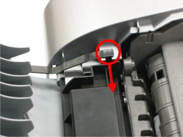
27 (2) Cassette, front door (paper output tray), and door damper removal - Pull out the cassette and remove it from the machine. - Warp the front door up a little and push its right side downward to remove it from the bottom case. - When removing the front door, remove the door damper from the hole of the bottom case, as shown in the photo. (3) Emblem removal - Push the point indicated by the arrow in the photo to remove from the double-sided adhesive tape. (4) Side cover (right and left) removal - Remove the 4 screws from the rear of the machine, screw from left front, and screw from the right front. - Using a flat-blade screwdriver, push the hooks downward to release them. -2

 Front")
 removal -")


28 Left hook Right hook Left side cover Right side cover (5) Front cover (right and left) removal - While pushing the hook with a flat-blade screwdriver, pull the front cover toward you to remove it. Left front cover Right front cover -22


 DF rear cover removal - Remove")

29 (6) DF front cover removal - Remove the screw. Release the hook while pushing it in the direction indicated by the arrow in the photo. (7) DF rear cover removal - Remove the screw. Release the hook while pushing it in the direction indicated by the arrow in the photo. - Slide the stop arm in the direction indicated by the arrow and remove the DF rear cover. -23


30 (8) Stop arm removal - Rotate the arm 90 degrees clockwise, pull it toward you to remove it. (9) DF grip cover and DF right cover removal - Remove the screws. A: DF grip cover screws B: DF right cover screws -24


31 (0) Document feed unit removal - Remove the 5 screws and connector. () Separation tab, document feed roller, and separation roller cleaning - Wipe them with a dry and soft clean cloth.. Document feed roller 2. Separation roller 3. Separation tab -25

32 (2) DF cable cover removal - Remove the 2 screws. Cable position: -26

 removal - Release 6 hooks")


33 (3) ADF hinge removal - Remove the 3 screws. (4) Operation panel (right and left) removal - Release 6 hooks each from the right and left operation panels. Left (5) LCD upper cover removal - Push the front end of the LCD upper cover upward with your fingers and remove it. - 4 hooks need to be released. Right -27


 LCD the screw and")
 Logic board ass'y")
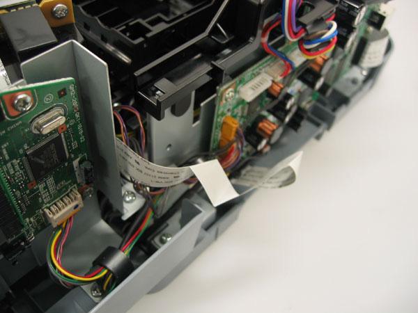
34 (6) Operation panel unit removal - Remove the 4 screws. - Remove the flat cable. (7) LCD unit removal - Remove the screw and disconnect the flat cable. (8) Logic board ass'y wiring -28


35 (9) Scanner stop arm removal - Shift the both left and right stopper outward, then lift the Scanner Stop Arm. -29

 Scanner unit removal - On the logic board, remove the flat cable from CN602, and remove the core.")
36 (20) Scanner stopper removal - While holding the stopper perpendicular to the scanner unit, slide the stopper in the direction indicated by the arrow and remove it from the scanner unit. (2) Cable holder sheet position - The cable holder sheet is attached to the prescribed location with double-sided adhesive tape. (22) Scanner unit removal - On the logic board, remove the flat cable from CN602, and remove the core. - On the logic board, remove the flat cables from CN80 and CN802, then remove 2 screws. - On the logic board, remove the harness from CN Remove the ground wire and core. -30


37 - Hold the scanner unit upright and lift the left stopper in the direction indicated by the arrow in the photo. - Slide the left of the scanner unit in the direction indicated by the arrow 2 in the photo, then slide the scanner unit in the direction of the arrow 3 and remove it. -3


 Base case")
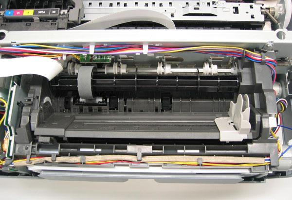
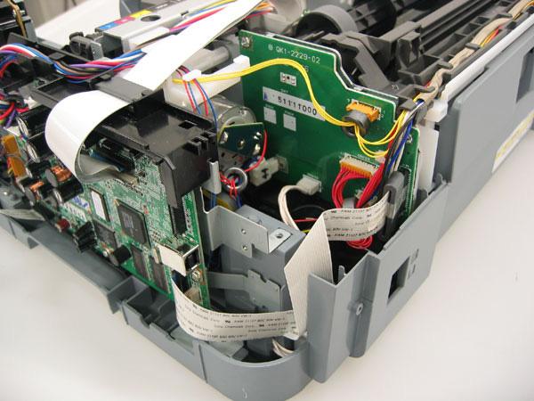
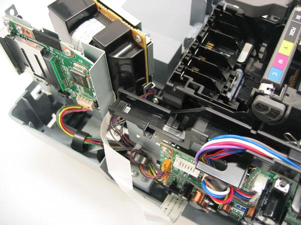
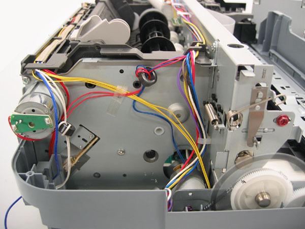
38 (23) Main case unit removal - Remove the 4 screws. - Disconnect the solenoid connector, and lift the main case unit. (24) Base case and printer unit wiring -32
39 -33
40 -34
41 -35

 Printer unit removal - Remove the 4 screws, and")
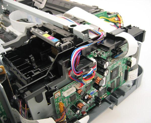
42 (25) Logic board ass'y removal - Remove all the flat cables and harnesses from the logic board. - Remove the 7 screws. (26) Printer unit removal - Remove the 4 screws, and lift the printer unit to remove it. -36


43 To the table of contents <Part : 3. REPAIR; 3-2. Special Notes on Repair Servicing> To the top -37
.")
44 3-3. Adjustment / Settings () Paper feed motor adjustment Perform the following adjustments when the paper feed motor unit is replaced: ) When attaching the motor, fasten the screws so that the belt is properly stretched (in the direction indicated by the blue arrow in the figure below). 2) After replacement, be sure to perform the service test print, and confirm that no strange noise or faulty print operation (due to dislocation of the belt or gear, or out-of-phase motor, etc.) occurs Note: The red screws securing the paper feed motor may be loosened only at replacement of the paper feed motor unit. DO NOT loosen them in other cases. (2) Grease application ) Machine unit No Part name Where to apply grease/ oil Grease/ oil name Chassis ass'y Entire surface the carriage slider contacts Floil KG07A Chassis ass'y PR lift shaft cam contact portion (at 3 Floil 2 locations) KG07A Adjust plate L Carriage shaft cam L sliding portion Floil 3 KG07A Chassis ass'y Carriage shaft sliding portion on the left side Floil 4 of the chassis (at 2 locations) KG07A Chassis ass'y Carriage shaft sliding portion on the right Floil 5 side KG07A of the chassis (at 2 locations) Carriage shaft Entire surface of the carriage shaft where Floil 6 the carriage unit slides KG07A Carriage shaft spring Carriage shaft sliding portion Floil 7 L (to the end of spring) KG07A Adjust plate R Carriage shaft cam R sliding portion Floil 8 KG07A Carriage shaft Carriage shaft surface where the carriage Floil 9 sliders KG07A (and where machine-application of the grease Grease/ oil amount 27 to 54 mg 9 to 8 mg 8to 36 mg 9 to 8 mg 9 to 8 mg 200 to 400 mg 9 to 8 mg 8 to 36 mg 9 to 8 mg Number of rops* Number of locations to apply grease/ oil


45 * drop = 9 to 8 mg is not feasible) 2) CL base / CL gear Number of Grease/ Number Grease/ oil locations to No Part name Where to apply grease/ oil oil of name apply amount drops* grease/ oil 0 CL input gear Joint of the CL gear base Floil KG07A 9 to 8 mg CL gear base Outer surface of the CL idler gear cylinder Floil KG07A 9 to 8 mg * drop = 9 to 8 mg -39

 Floil KG07A 3.5 to 27 mg.5 4 4) Open button To the table of contents <Part : 3.")
46 3) PR shaft / LF roller bushing No Part name Where to apply grease/ oil * drop = 9 to 8 mg Grease/ oil name Grease/ oil amount Number of drops* Number of locations to apply grease/ oil 2 LF roller ass'y LF roller bushing l spriong contact Floil KG07A 4.5 to 9 mg /2 3 PR shaft ass'y PR spring sliding portion (at 4 locations) Floil KG07A 9 to 8 mg 4 4 PR shaft ass'y PR holder contact (at 4 locations) Floil KG07A 3.5 to 27 mg.5 4 4) Open button To the table of contents <Part : 3. REPAIR, 3-3 () to (2)> To the top -40
.")
47 (3) Waste ink counter setting Before replacement of the logic board ass'y, check the waste ink amount. After the logic board ass'y is replaced, set the waste ink amount to the replaced logic board ass'y. In addition, according to the waste ink amount, replace the waste ink absorber (ink absorber kit). When the waste ink absorber is replaced, reset the waste ink counter (to "0%"). How to check the waste ink amount: See 3-4. Verification Items, () Service test print, or (2) EEPROM information print. How to set the waste ink amount: See 3-3. Adjustment / Settings, (6) Service mode, "Waste ink amount setting procedures." (4) White sponge sheet attachment Position one of the corners of the white sponge sheet at the scanning reference point on the platen glass (back left where the blue lines cross in the photo below). Peel off the cover sheet from the double-sided adhesive tape, and slowly close the document cover with the sponge frame on. The sponge sheet will attach to the sponge frame. Open the document cover to confirm the following: - No extension of the sponge edges over the mold part of the document cover. - No gap between the platen glass reference edges and the corresponding sponge edges. (5) User mode Function Procedures Remarks Print head manual cleaning See "Standalone machine operation" below, or perform from the MP driver Maintenance tab. Print head deep cleaning See "Standalone machine operation" below, or perform from the MP driver Maintenance tab. Paper feed roller cleaning See "Standalone machine operation" below. Nozzle check pattern printing See "Standalone machine operation" below, or perform from the MP driver Maintenance tab. Print head alignment (automatic / manual) Bottom plate cleaning Print head replacement See "Standalone machine operation" below, or perform from the MP driver Maintenance tab. See "Standalone machine operation" below, or perform from the MP driver Maintenance tab. The print head is replaceable at the same position as for ink tank replacement. (Open the scanning unit. When the carriage stops at the center, the print head can be replaced.) In Custom Settings of the MP driver Maintenance tab, manual print head alignment (by selecting the optimum values) as with the conventional models can be performed. Cleaning of the platen ribs when the back side of paper gets smeared. -4
48 <Standalone machine operation> Turn on the machine. On the operation panel, select Maintenance/settings, Maintenance or Device settings, then a desired function. Nozzle check Menu (nozzle check pattern print) Cleaning Deep cleaning Auto head align (automatic print head alignment) Manual head align (manual print head alignment) Roller cleaning Bottom plate cleaning Prevent paper abrasion (head-to-paper distance setting) Adjust contrast Remarks Set a sheet of A4 or letter size plain paper in the ASF or cassette (according to the Feed Switch button setting). Set a sheet of A4 or letter size plain paper in the ASF. Set 2 sheets of A4 or letter size plain paper in the ASF or cassette (according to the Feed Switch button setting). Set 3 or more sheets of A4 or letter size plain paper in the ASF or cassette to be cleaned. Fold a sheet of A4 or letter size plain paper in half, then open it. Set the paper in the ASF with the opened surface facing up. (6) Service mode Function Procedures Remarks Service test print - Model name - Destination - ROM version - USB serial number - Waste ink amount - CD / DVD sensor correction value - Ink system function check result - CD / DVD sensor correction result EEPROM information print - Model name - Destination - ROM version - Waste ink amount - Print information - Error information See "Service mode operation procedures" below. See "Service mode operation procedures" below. Set a sheet of A4 or letter size paper. For print sample, see 3-4. Verification Items, () Service test print, <Service test print sample>. Set a sheet of A4 or letter size paper. EEPROM initialization Waste ink counter reset See "Service mode operation procedures" below. See "Service mode operation procedures" below. The following items are NOT initialized, and the shipment arrival flag is not on: - USB serial number - Destination settings - Waste ink counter - CD / DVD correction value If the waste ink amount is 7% or more, replace the ink absorber kit. -42
49 Destination settings LF correction Button and LCD test Waste ink amount setting See "Service mode operation procedures" below. See "Service mode operation procedures" below. See "Service mode operation procedures" below. See "Service mode operation procedures" below. Initialize EEPROM after the destination settings. Note: At the end of the service mode, press the ON/OFF button. The paper lifting plate of the sheet feed unit will be raised. <Service mode operation procedures> ) With the machine power turned off, while pressing the Stop/Reset button, press and hold the ON/OFF button. (DO NOT release the buttons). The COPY button lights in green to indicate that a function is selectable. 2) While holding the ON/OFF button, release the Stop/Reset button. (DO NOT release the ON/OFF button.) 3) While holding the ON/OFF button, press the Stop/Reset button 2 times, and then release both the ON/OFF and Stop/Reset buttons. (Each time the Stop/Reset button is pressed, the Alarm LED and COPY button light alternately, Alarm in orange and COPY in green, starting with Alarm LED.) 4) When the COPY button lights in green, press the Stop/Reset button the specified number of time(s) according to the function listed in the table below. (Each time the Stop/Reset button is pressed, the Alarm LED and COPY button light alternately, Alarm in orange and COPY in green, starting with Alarm LED.) Time(s) LED indication Function Remarks 0 times Green (COPY) Power off When the print head is not installed, the carriage returns and locks in the home position capped. time Orange (Alarm) Service test print See 3-4. Verification Items, () Service test print. 2 times Green (COPY) EEPROM information print See 3-4. Verification Items, (2) EEPROM information print. 3 times Orange (Alarm) EEPROM initialization 4 times Green (COPY) Waste ink counter resetting 5 times Orange (Alarm) Destination settings See "Destination settings procedures" below. 6 times Green (COPY) Print head deep cleaning Cleaning of both black and color 7 times Orange (Alarm) LF correction See "LF correction procedures" below. 8 times Green (COPY) CD / DVD check pattern print Not used in servicing 9 times Orange (Alarm) CD / DVD print position Not used in servicing. correction (horizontal: X direction) 0 times Green (COPY) CD / DVD print position Not used in servicing. correction (vertical: Y direction) times Orange (Alarm) Button and LCD test See "Button and LCD test procedures" below. 2 times Green (COPY) Return to the menu selection 3 times Orange (Alarm) Return to the menu selection 4 times Green (COPY) Left margin correction Not used in servicing. 5 times Orange (Alarm) Waste ink amount setting See "Waste ink amount setting procedures" below. 6 times or more Green at even numbers (COPY) Orange at odd numbers (Alarm) Return to the menu selection Note: - If the Stop/Reset button is pressed 6 or more times, the Alarm LED (orange) or COPY button (green) lights steadily without any changes. - At the end of the service mode, press the ON/OFF button. The paper lifting plate of the sheet feeder unit will be raised. -43
50 <Destination settings procedures> In the destination settings mode, press the Stop/Reset button the specified number of time(s) according to the destination listed in the table below, and press the ON/OFF button. Time(s) LED indication Destination CD / DVD print 0 times Green (COPY) No change of the destination time Orange (Alarm) Japan Supported 2 times Green (COPY) Korea Not supported 3 times Orange (Alarm) US Not supported 4 times Green (COPY) Europe Supported 5 times Orange (Alarm) Australia Supported 6 times Green (COPY) Asia Supported 7 times Orange (Alarm) China Supported 8 times Green (COPY) Taiwan Supported 9 times or more Orange (Alarm) Return to the menu selection Note: After setting the destination without logic board replacement, be sure to initialize the EEPROM. Without EEPROM initialization, the destination settings may not be valid. Confirm the model name and destination in service test print or EEPROM information print. [See 3-4. Verification Items, () Service test print, or (2) EEPROM information print.] <LF correction procedures> After replacement of the feed roller ass'y or logic board ass'y in repair servicing or in refurbishment operation, adjust the line feeding. ) In the LF correction mode, press the Stop/Reset button the specified number of times according to the paper to be used in LF correction listed in the table below, then press the ON/OFF button. Time(s) Paper type Paper name time High Resolution Paper Canon HR-0 2 times Canon PB PAPER GF-500 (64 g/m 2 ), Canon Office Planner 3 times Plain paper HP BrightWhite (90 g/m 2 ), Canon Office (80 g/m 2 ) 4 times Canon Extra, STEINBEIS Vision Classic White Note: - The High Resolution Paper is the most desirable for LF correction printing (Canon HR-0 is used at the production site), but 6 kinds of plain paper listed in the table above can also be used in LF correction. If plain paper other than the above is used, select any one of the paper types in this step, then select Pattern No. 0 (zero) in the step 3) below. - Each time the Stop/Reset button is pressed, the Alarm LED and the COPY button light alternately, Alarm in orange and COPY in green. - If the Stop/Reset button is NOT pressed, and only the ON/OFF button is pressed, the machine remains in the LF correction mode. - If the Stop/Reset button is pressed 5 times or more, then the ON/OFF button is pressed, the machine returns to the service mode menu selection. -44
 are the least noticeable, press the Stop/Reset button the same number of time(s) as the selected Pattern No., then press the ON/OFF button.")

51 2) The LF correction pattern for the selected paper is printed. 3) In the printout, select the Pattern No. in which streaks or lines (white or black) are the least noticeable, press the Stop/Reset button the same number of time(s) as the selected Pattern No., then press the ON/OFF button. Note: - If plain paper other than the 6 kinds specified in the table in step ) is used, select the Pattern No. 0 (zero), leave the Stop/Reset button untouched, and press the ON/OFF button. - Each time the Stop/Reset button is pressed, the Alarm LED and the COPY button light alternately, Alarm in orange and COPY in green. - If the Stop/Reset button is pressed 3 times or more, then the ON/OFF button is pressed, the machine returns to the service mode menu selection. -45
52 4) The LF correction value is written to the EEPROM, and the machine returns to the service mode menu selection. Note: The LF correction value (0,, or 2) can be confirmed in EEPROM information print. <Waste ink amount setting procedures> Set the waste ink amount data to a replaced new EEPROM after the logic board is replaced in servicing. ) Before replacement of the logic board ass'y, check the waste ink amount in EEPROM information print. [See 3-4. Verification Items, (2) EEPROM information print.] 2) In the waste ink amount setting mode, press the Stop/Reset button the specified number of time(s) according to the waste ink absorber whose value should be transferred to the replaced new EEPROM. (Only the main waste ink absorber for the MP830) Time(s) Waste ink absorber Remarks 0 times Main waste ink absorber time Platen waste ink absorber Not valid for the MP830 2 times Both the main and platen waste ink absorbers Only the main waste ink absorber is valid for the MP830 3 times or more Not valid Press the ON/OFF button to return to the waste ink amount setting mode. 3) Press the ON/OFF button to proceed to the next step. 4) The waste ink amount can be set in 0% increments by pressing the Stop/Reset button. Press the Stop/Reset button the appropriate number of time(s) to select the value which is closest to the actual waste ink amount. Time(s) Waste ink amount value to be set (%) 0 times 0% time 0% 2 times 20% 3 times 30% 4 times 40% 5 times 50% 6 times 60% 7 times 70% 8 times 80% 9 times 90% 0 times or more Not valid. Press the ON/OFF button to return to the waste ink amount setting mode. -46
 In the button and LCD test mode, press the Stop/Reset button.")


53 5) Press the ON/OFF button to set the selected value to the EEPROM. Print EEPROM information to confirm that the value is properly set to the EEPROM. <Button and LCD test procedures> Confirm the operation after replacement of the operation panel unit or LCD unit. ) In the button and LCD test mode, press the Stop/Reset button. The LCD turns blue, waiting for a button to be pressed. 2) Press each button on the left half of the operation panel (total 9 buttons). The LCD is divided into segments, representing each button. The color of a segment corresponding to the pressed button changes to red. Each time a button is pressed, the COPY button and Alarm LED lights alternately, COPY in green and Alarm in orange. When all the 9 buttons are pressed, the entire LCD changes to a full light blue screen. 3) Press each button on the right half of the operation panel (total 27 buttons). The LCD is divided into segments, representing each button. The color of a segment corresponding to the pressed button changes to red. Each time a button is pressed, the COPY button and Alarm LED lights alternately, COPY in green and Alarm in orange. When all the 27 buttons are pressed, the entire LCD changes to a full red screen, and no further pressing of the button is accepted. -47
 above), even the Stop/Reset button is not accepted. 5) Press the ON/OFF button to return to the service mode menu selection.")
54 4) Open the scanning unit (printer cover) to display the color pattern. Only the ON/OFF button is enabled. If there is any button left un-pressed (a blue segment remained in step 3) above), even the Stop/Reset button is not accepted. 5) Press the ON/OFF button to return to the service mode menu selection. To the table of contents To the top <Part : 3. REPAIR; 3-3. Adjustment / Settings (3) to (6)> -48
55 3-4. Verification Items () Service test print <EEPROM information contents> On the service test print (sample below), confirm the EEPROM information as shown below. (The information is given in the upper portion of the printout.) MP830: Model name JPN: Destination M = x.xx: ROM version C = x.xx: Not used in servicing USB (xxxxxx): USB serial number FA = xx xx xx: Reserved for plant use D = xxx.x: Waste ink amount (%) CDR (+xxxxx, +yyyyy): CD / DVD sensor position correction value LF = x: LF correction value (0 to 2) AB (K = OK Y =...): Ink system function check result <Print check items> On the service test print (sample below), confirm the following items: - Check, top of form accuracy: The lines shall not extend off the paper. - Check 2, EEPROM information - Check 3, nozzle check pattern: Ink shall be ejected from all nozzles. - Check 4, check pattern for irregular line feeding: There shall be no remarkable streaks or unevenness. - Check 5, check pattern for uneven printing due to line feeding: There shall be no remarkable streaks. - Check 6, check pattern for uneven printing due to carriage movement (9600 dpi mode): There shall be no remarkable unevenness. - Check 7, check pattern for uneven printing due to carriage movement (standard mode): There shall be no remarkable unevenness. - Check 8, CD / DVD sensor and automatic print head alignment sensor correction: The results shall be OK. -49
 8: LPT=2006/05/0-2:09 9: PC(M=002 R=000 T=00 D=009 C=000) 0: CLT(BK=2006/0/28-8:38 CL=2006/0/28-8:38) : CH=00002 2: CT(PBK=02 BK=05 Y=03 M=00 C=00) 3:")
56 <Service test print sample> (2) EEPROM information print <How to read EEPROM information print> Print sample: : MP830 2: JPN 3: V.00 4: IF(USB2=) 5: D=020. 6: ST=2006/0/28-8:30 7: ER(ER0=300 ER=500) 8: LPT=2006/05/0-2:09 9: PC(M=002 R=000 T=00 D=009 C=000) 0: CLT(BK=2006/0/28-8:38 CL=2006/0/28-8:38) : CH= : CT(PBK=02 BK=05 Y=03 M=00 C=00) 3: IS(PBK=2 BK=0 Y=2 M=0 C=0) 4: P_ON(S=00009) 5: A_REG= 6: M_REG=0 7: UR(A(BKoe)=-0 B(Coe)=-02 C(Moe)=000 D(SCoe)=+0 E(SMoe)=+0 F(PBKoe)=000 G(CLbi)=000 H(SCLbi)=+0 I(C-SC)=-0 J(M-SM)=000 K(BK-CL)=+0 L(BKbiPP)=000 M(CLbiPP)=000 N(SCLbiPP)=000 O(NZctr)=000 P(NZedge)=000-50
57 8: WP=0024 9: CDIN(LG=00 PB=000 OPB=000) 20: MSD(002) 2: TPAGE=0062 (TTL=0062 FAX=00000 COPY=00000) 22: PAGE(All=0042 PP=0040 HR+MP=00000 PR+SP+SG=00002 GP=00000 PC=00000 EV=00000) 23: UCPAGE(All=00020 PP=0003 HR+MP=00000 PR+SP+SG=00007 GP=00000 PC=00000 EV=00000) 24: BPPAGE(All=00000 BSSP=00000 PC=00000) 25: CDPAGE(All=00000) 26: EDGE= : L= : CDR= : CDRP=(+00498, ) 30: CDRS=(30) 3: LF= 32: LM=(ASF_R:00 UT_F:00 UT_R:00) <Direct> 33: LG=0 Japanese 34: SC=000 35: Seal=000 36: CDI=007 37: CDP=002 38: CDD-PR(L=000 2L=000 PC=000 A4=000) 39: CDD-SP(L=000 2L=000 PC=000 A4=000) 40: CDD-MP(L=000 2L=000 PC=000 A4=000) 4: DCD-PP(L=000 2L=000 PC=000 A4=000) 42: DCD-FPP(L=000 2L=000 PC=000 A4=000) 43: DCD-MPP(L=000 2L=000 PC=000 A4=000) <Scanner> 44: SC= : SC-dpi(75= = = = = = =00000) 46: SG(GY=00003 CL=00002) <Copy> 47: MCASF(PP=00000 SP+PR+GP=00000 OTH=00000) 48: MCUT(PP=00000 SP+PR+GP=00000 OTH=00000) 49: CCASF(PP=00000 HR+MP=00000 PR+SP+SG=00000 GP=00000 PC=00000) 50: CCUT(PP=00000 HR+MP=00000 PR+SP+SG=00000 GP=00000 PC=00000) <FAX> 5: TX=00002 (Bk=00002 Cl=00000) 52: SIZE(A4=00002) 53: RX= : SIZE(A4=0000) 55: FXSP= : Head TempBK= : Head TempC= : Env Temp= : FF( F) HDEEPROM 60: V000 6: SN= F 62: LN( ) 63: ID=09 64: IL(PBK=000 BK=000 Y=000 M=000 M2=000 C=000 C2=000) 65: <SCAN ERROR HISTORY> : <FAX USER ERROR HISTORY> : <FAX SERVICE ERROR HISTORY> Printed items:. Model name 2. Destination 3. ROM version 4. Connected I/F (USB2) 5. Waste ink amount (%) 6. Installation date & time 7. Operator call/service call error record 8. Last printing date & time 9. Purging count (manual/deep cleaning/timer/dot count/ink tank and print head replacement) 0. Cleaning date & time (BK/CL). Print head replacement count 2. Ink tank replacement count (PBK/BK/Y/M/C) 3. Ink status (PBK/BK/Y/M/C) 4. Power-on count (soft) 5. Automatic print head alignment by user 6. Manual print head alignment by user 7. User print head alignment values (Bkoe/Coe/Moe/SCoe/SMoe/PBKoe/CLbi/SCLbi/C-SC/M-SM/BK- CL/BKbiPP/CLbiPP/SCLbiPP/NZctr/NZedge) 8. Wiping count 9. Camera Direct Print-supported device connection record (LG = Legacy, PB = Canon PictBridge-supported camera, OPB = Other PictBridge-supported camera) 20. Longest period where printing stops (days) 2. Total print pages (total, fax, copy pages) 22. ASF feed pages (total, plain paper, High Resolution Paper & Matte Photo Paper, Photo Paper Pro & Photo Paper Plus Glossy & Photo Paper Plus Semi-gloss, Glossy Photo Paper, postcard, Envelope) 23. U-turn cassette feed pages (total, plain paper, High Resolution Paper & Matte Photo Paper, Photo Paper Pro & Photo Paper Plus Glossy & Photo Paper Plus Semi-gloss, Glossy Photo Paper, postcard, envelope) 24. Auto duplex print pages (total, Photo Paper Plus Double Sided, postcard) -5
58 25. Camera Direct print pages (total) 26. Borderless print pages (total) 27. 4x6 print pages 28. Number of CDs and DVDs printed 29. CD / DVD print position adjustment value 30. CD / DVD sensor correction value 3. LF correction 32. Left margin correction value (ASF back side, U-turn front side, U-turn back side), not used in servicing the MP830 <Direct> 33. Language 34. Business card & Credit card sized paper pages fed 35. Sticker sheets fed 36. Memory card use count 37. Total Card Direct print pages 38. Card Direct print pages: Photo Paper Pro (4 x 6, 5 x 7, Japanese post card, A4/Letter) 39. Card Direct print pages: Photo Paper Plus Glossy (4 x 6, 5 x 7, Japanese post card, A4/Letter) 40. Card Direct print pages: Matte Photo Paper (4 x 6, 5 x 7, Japanese post card, A4/Letter) 4. Camera Direct print pages: Photo Paper (4 x 6, 5 x 7, Japanese post card, A4/Letter) 42. Camera Direct print pages: Fast Photo Paper (4 x 6, 5 x 7, Japanese post card, A4/Letter) 43. Camera Direct print pages: Matte Photo Paper (4 x 6, 5 x 7, Japanese post card, A4/Letter) <Scanner> 44. Total scan count 45. Scan count by scanning resolution (75, 50, 300, 600, 200, 2400, 4800 dpi) 46. Scan count by scanning gradation (grayscale, color) <Copy> 47. Monochrome copy pages fed via the ASF (plain paper, Photo Paper Plus Glossy & Photo Paper Pro & Glossy Photo Paper, other) 48. Monochrome copy pages fed via the U-turn cassette (plain paper, Photo Paper Plus Glossy & Photo Paper Pro & Glossy Photo Paper, other) 49. Color copy pages fed via the ASF (plain paper, High Resolution Paper & Matte Photo Paper, Photo Paper Pro & Photo Paper Plus Glossy & Photo Paper Plus Semi-gloss, Glossy Photo Paper, postcard) 50. Color copy pages fed via the U-turn cassette (plain paper, High Resolution Paper & Matte Photo Paper, Photo Paper Pro & Photo Paper Plus Glossy & Photo Paper Plus Semi-gloss, Glossy Photo Paper, postcard) <Fax> 5. Transmission count (monochrome, color) 52. Transmitted pages 53. Reception count 54. Received pages 55. Communication speed st line: 33.6/3.2/28.8/26.4/24.0/2.6/9.2/6.8/4.4/2.0/9.6/7.2/4.8/2.4 kbps 2nd line: TC4400/TC2000/TC9600/TC7200/9600/7200/4800/2400 bps The number of communication pages at each communication speed is indicated in hex. 56. Print head temperature (BK) 57. Print head temperature (CL) 58. Inside temperature 59. Line inspection information (not used in servicing) HDEEPROM 60. Version 6. Serial number 62. Lot number 63. Print head ID 64. Ink ejection level (PBK, BK, Y, M, M2, C, C2) <Scan error history> 65. The last 2 errors (including user errors and copy scan errors. Even if the same errors occur, they are recorded individually.) <Fax user error history> 66. The last 2 errors <Fax service error history> 67. The last 2 errors -52
59 (3) Fax report <User report output> The user report can be output manually by user operation, or automatically via the user data settings. ) Reports manually output by user operation Report One-touch speed dialing list Coded speed dialing list Group dialing list User's data list Activity report Memory list Operation Press the FAX button, then Menu button. Using the right or left cursor button, select Print report/list, and the item desired, then press the OK button. 2) Reports automatically output - Multi activity report: Automatically output at the end of broadcast. 3) Reports automatically output via the user data settings - Transmission report - Reception report - Activity report Memo: The current ROM version (e.g..0) is printed in the upper left of the user's data list. In troubleshooting, check the ROM version. Note: If the machine is turned off by removing the power cord with image data remained in the memory, the image data will be erased. However, the memory clear list will not be printed at next power-on. <Service report output> The service data setting status, communication report, and error information report can be output via the service data settings. ) Reports for service use System data list Report Transmission report (with service error code and dump list) Operation In the user mode, press and hold the Stop/Reset button until the Alarm LED blinks 3 times in orange, then release the button. In service data # SSSW SW0, set bit 0 and bit to "." The service error code and dump list will be added to the transmission report. For details, see <How to set SSSW> below. Reception report (with service error code and dump list) In service data # SSSW SW0, set bit 0 and bit to "." The service error code and dump list will be added to the reception report. For details, see <How to set SSSW> below. <How to set SSSW> ) In the user mode, press and hold the Stop/Reset button until the Alarm LED blinks 2 times in orange, then release the button. 2) "SERVICE MODE SERVICE MODE # BIT SWITCH" is displayed on the LCD to indicate the machine is in the SSSW mode. 3) Press the OK button. "SW# " will additionally be displayed on the LCD. 4) Using the right or left cursor button, set bit 2 (the rightmost digit (LSB)) and bit (the second digit from the right) to "." 5) Press the OK button. 6) Press the Stop/Reset button. 7) Press the ON/OFF button to turn off the machine. -53
60 <System data list sample> -54
61 <Transmission report sample> *: Transaction number (4 digits) -55
62 *2: The number sent from the other party or dialed on the machine (the last 20 digits) *3: ID sent from the other party, when the other party is a Canon fax *4: Communication start date and time (in 24-hour display) *5: Communication duration (in minutes and seconds) *6: The number of pages completely transmitted *7: "NG" and service error code To the table of contents <Part : 3. REPAIR; 3-4. Verification Items> To the top -56
 In the service mode, press the ON/OFF button to finish the mode, and confirm that the paper lifting plate of the sheet feed unit is raised.")
63 4. MACHINE TRANSPORTATION This section describes the procedures for transporting the machine for returning after repair, etc. ) In the service mode, press the ON/OFF button to finish the mode, and confirm that the paper lifting plate of the sheet feed unit is raised. 2) Keep the print head and ink tanks installed in the carriage. [See Caution below.] 3) Turn off the machine to securely lock the carriage in the home position. (When the machine is turned off, the carriage is automatically locked in place.) [See Caution 2 below.] 4) Slide the scanner lock switch to lock the scanner. Caution: () If the print head is removed from the machine and left alone by itself, ink (the pigment-based black ink in particular) is likely to dry. For this reason, keep the print head installed in the machine even during transportation. (2) Securely lock the carriage in the home position, to prevent the carriage from moving and applying stress to the carriage flexible cable, or causing ink leakage, during transportation. Memo: If the print head must be removed from the machine and transported alone, attach the protective cap (used when the packing was opened) to the print head (to protect the print head face from damage due to shocks). To the table of contents <Part : 4. MACHINE TRANSPORTATION> To the top -57
64 Part 2 TECHNICAL REFERENCE
65 . NEW TECHNOLOGIES () Ink tank system (PGI-5, CLI-8) An LED is installed in each ink tank. By the LED indication, wrong installation of the ink tanks will be prevented, and the remaining ink level can be visually recognized with the ink tanks seated in the carriage. The pigment-based black ink (PGI-5BK) with higher resistance against bleeding or marker pens increases weather resistance of photo quality prints. The combination of the pigment-based black ink and the dye-based inks (CLI-8 series) makes the ink system strong in both photo and text printing. (2) Super-photo quality printing By the FINE technologies, pl of ultra-fine ink droplet is adopted. The MP830 provides excellent super-photo print quality without graininess at the maximum resolution of 9,600 dpi x 2,400 dpi *, which is equal to that of a 6-color machine. *: Printing at the minimum distance of /9600 inch between the dots. (3) High-speed print and copy Print speed: Approx. 36 sec. in 4" x 6" borderless printing (standard mode, Photo Paper Plus Glossy, full page, SCID No.2) For reference, 30 ppm in monochrome printing and 24 ppm in color printing Copy speed: 29 cpm in monochrome copy and 24 cpm in color copy (4) New functionality in Direct Printing (same as the MP800's) - Plain paper is now usable in Camera Direct Printing from a digital camera or digital video camera, if both support PictBridge. - File numbers and shooting information can be printed on the images. - Optimization of photos taken by a mobile phone: Minimizes jaggies in printing a low-resolution photo taken by a mobile phone. - Writing to a memory card: The memory card can be set to the Read-only or Read/Write mode. - Slide show: To the Single-photo print menu, the slide show function has been added to display photos from the memory card one by one automatically. - Red eye correction: Selects red area from an image, and detects and corrects the red eye automatically. - Face brightener: Perceives a person's face automatically and adjusts its brightness. - Index printing: Printing like a 35 mm negative film is possible. (5) Sophisticated and smooth design Sophisticated and classy ADF-integrated all-in-one design. (6) USB 2.0 Hi-Speed supported The printer supports USB 2.0 Hi-Speed, enabling high speed data transfer in use with the computer. (7) High-definition 2.5 color STN LCD The color tilt LCD offers higher visibility (76 x 32 pixels, approx. 65,000 colors). (8) 2,400 x 4,800 dpi high-resolution CCD scanner (9) ADF (Automatic Document Feeder) Up to 35 sheets can be set, and automatic duplex printing is available. 2-
66 (0) Fax - 00 coded speed dials page reception in the memory (based on the Canon standard transmission chart) - Super G3 high speed fax To the table of contents To the top <Part 2:. NEW TECHNOLOGIES> 2-2
67 2. CLEANING MODE AND AMOUNT OF INK PURGED To prevent printing problems due to bubbles, dust, or ink clogging, print head cleaning is performed before the start of printing (when the cleaning flag is on), except in the following cases: - Cleaning on arrival: Performed when the scanning unit (printer cover) is closed. - Manual cleaning / deep cleaning: Performed manually. <Cleaning mode list> Black: Pigment-based black Color: Dye-based black, cyan, magenta, yellow Condition On arrival of the machine (All in sequence) Dot count cleaning (Black) Timer cleaning - 0 *2 (Black only) Timer cleaning - (Black only) Timer cleaning - 2 (Black only) Timer cleaning - 3 *3 (Black/Color) Timer cleaning - 4 (All in sequence) Timer cleaning - 5 (All in sequence) Timer cleaning - 6 (All in sequence) Timer cleaning - 7 (All in sequence) Timer cleaning - 8 (All in sequence) Timer cleaning - 9 (All in sequence) Timer cleaning - 0 (All in sequence) At print head replacement (All in sequence) At ink tank replacement *4 (Black/Color/All in sequence) Manual cleaning (Black/Color/All at the Details First to third cleaning after shipped from the plant *. When the specified number of dots are printed since the previous Black cleaning. If 24 to 60 hours have elapsed since the previous Black cleaning till the start of the next printing. If 60 to 96 hours have elapsed since the previous Black cleaning till the start of the next printing. If 96 to 20 hours have elapsed since the previous Black cleaning till the start of the next printing. If 20 to 336 hours have elapsed since the previous Black/Color cleaning till the start of the next printing. If 336 to 504 hours have elapsed since the previous Black/Color cleaning till the start of the next printing. If 504 to 720 hours have elapsed since the previous Black/Color cleaning till the start of the next printing. If 720 to,080 hours have elapsed since the previous Black/Color cleaning till the start of the next printing. If,080 to 2,60 hours have elapsed since the previous Black/Color cleaning till the start of the next printing. If 2,60 to 4,320 hours have elapsed since the previous Black/Color cleaning till the start of the next printing. If 4,320 to 8,640 hours have elapsed since the previous Black/Color cleaning till the start of the next printing. If 8,640 or longer hours have elapsed since the previous Black/Color cleaning till the start of the next printing. When the print head is removed and installed. When an ink tank is replaced (without the print head removal or re-installation) - Via the operation panel (All at the same time only) - Via the MP driver (Selectable from Black, Color, 2-3 Amount of ink used (g) (in the normal temperature/humidity environment) 0.57 (Black) 2.25 (Color) Est. required time (sec.) (not including the time of opening the caps) (Black) 35 (Black) 0.20 (Black) 35 (Black) 0.20 (Black) 0.66 (Color) 0.57 (Black).06 (Color).27 (Black).06 (Color).95 (Black).06 (Color).95 (Black).06 (Color) 0.57 (Black) 2.25 (Color) 0.38 (Black).06 (Color) 0.20 (Black) 0.65 (Color) 35 (Black) 40 (Color) (All in sequence) 40 (Black) 65 (Color) 45 (All at the same time)
68 same time) or All at the same time) 35 (Black) 40 (Color) Deep cleaning (Black/Color/All at the same time) Via the MP driver (Selectable from Black, Color, or All at the same time).95 (Black).06 (Color) 90 (All at the same time) 45 (Black) 65 (Color) If the print head has not been capped before power-on (All in sequence) 0.38 (Black).06 (Color) 80 (All in sequence) *: The counter for the on-arrival cleaning is checked at opening and closing of the scanning unit (the first opening and closing only), before start of printing, at dot-count cleaning (at paper ejection), and at manual cleaning, and the on-arrival cleaning is performed according to the counter value. After each on-arrival cleaning, the counter value is reduced by. When the counter value is 3, 2, or : On-arrival cleaning is performed. When the counter value is 0: On-arrival cleaning is not performed. *2: When 24 to 60 hours have elapsed since the previous Black cleaning, timer cleaning - 0 is performed. However, this cleaning will be conducted up to 5 times from the printer installation, and no further timer cleaning - 0 will be performed. *3: The period of time since the previous cleaning is counted by Black and Color separately. For this reason, the cleaning mode may differ according to Black or Color. *4: When only the black ink tank is replaced, Black cleaning is performed. One of the color ink tanks is replaced, Color cleaning is performed. Both the black and color ink tanks are replaced, All-at-the-same-time cleaning is performed. To the table of contents To the top <Part 2: 2. CLEANING MODE AND AMOUNT OF INK PURGED> 2-4
69 3. PRINT MODE Default setting Selectable in the printer driver Main tab Selectable after clicking Custom in the Main tab Ink used Print control PigBk: PGI-5BK C: CLI-8C(small droplet) M: CLI-8M(small droplet) Y: CLI-8Y k: CLI-8BK c: CLI-8C(small droplet) m: CLI-8M(small droplet) Bi: Bi-directional Uni: Uni-directional 3-. Normal Color Printing via Computer Paper type (Canon specialty paper) Plain paper Photo Paper Pro (PR-0) Photo Paper Plus Glossy Photo Paper Plus Semigloss (PP-0/SG-0) Photo Paper Plus Double Sided (PP-0D) Matte Photo Paper (MP-0) Glossy Photo Paper (GP-40/50) High Resolution Paper (HR-0) Envelope CD-R/DVD (recommended) CD-R/DVD (others) Item Print quality Resolution HxV (dpi) Print control Ink used Print quality Resolution HxV (dpi) Print control Ink used Print quality Resolution HxV (dpi) Print control Ink used Print quality Resolution HxV (dpi) Print control Ink used Print quality Resolution HxV (dpi) Print control Ink used Print quality Resolution HxV (dpi) Print control Ink used Print quality Resolution HxV (dpi) Print control Ink used Print quality Resolution HxV (dpi) Print control Ink used Print quality Resolution HxV (dpi) Print control Ink used Print quality Resolution HxV (dpi) 5 Fast Custom 300X300 pass, Bi PigBk/C/M/Y 2-5 MP driver Custom setting Fine Fast 300X300 pass, Bi PigBk/C/M/Y Fast 200X passes, Bi Standard 200X200 pass, Bi PigBk/C/M/Y Standard 200X passes, Bi Standard 200X passes, Bi Standard 200X passes, Bi Standard 200X passes, Bi Standard 200X passes, Bi Standard 200X passes, Bi Standard 200X200 2 passes, Bi PigBk/C/M/Y/k Fast 200X passes, Bi Fast 200X2400 High 200X passes, Bi PigBk/C/M/Y/c/m High 200X passes, Bi High 200X passes, Uni High 200X passes, Bi High 200X passes, Bi High 200X passes, Bi High 200X passes, Bi High 200X200 4 passes, Bi PigBk/C/M/Y/k Standard 200X passes, Bi C/M/Yc/m//k Standard 200X2400 Custom 9600X passes, Bi High 200X200 8 passes, Bi High 200X2400
70 Print control Ink used 4 passes, Bi 6 passes, Bi 8 passes, Bi T-Shirt transfer (TR-30) Print quality Resolution HxV (dpi) Print control Ink used High 200X200 6 passes, Bi C/M/Y/k Transparency (CF-02) Print quality Resolution HxV (dpi) Print control Ink used Standard 200X200 4 passes, Bi PigBk/C/M/Y/k High 200X200 6 passes, Bi PigBk/C/M/Y/k Other Photo Paper Print quality Resolution HxV (dpi) Print control Ink used Standard 200X passes, Bi 3-2. Normal Grayscale Printing via Computer MP driver Custom setting Paper type (Canon specialty paper) Item 5 Fast Fine Plain paper Print quality Resolution HxV (dpi) Print control Ink used Custom 300X300 pass, Bi PigBk Fast 300X300 pass, Bi PigBk Standard 600X600 pass, Bi PigBk High 600x600 4 passes, Bi PigBk Envelope Print quality Resolution HxV (dpi) Print control Ink used Standard 600X600 2 pass-uni PigBk High 600X600 4 pass-uni PigBk 2-6
71 3-3. Borderless Printing via Computer MP driver Custom setting Paper type (Canon specialty paper) Item 5 Fast Fine Plain paper Print quality Resolution HxV (dpi) Print control Ink used Standard 200X200 2 passes, Bi C/M/Y/k Photo Paper Pro (PR-0) Print quality Resolution HxV (dpi) Print control Ink used Standard 200X passes, Bi High 200X passes, Bi Custom 9600X passes, Bi Photo Paper Plus Glossy Photo Paper Plus Semi-gloss (PP-0/SG-0) Print quality Resolution HxV (dpi) Print control Ink used Fast 200X passes, Bi Standard 200X passes, Bi High 200X passes, Bi Glossy Photo Paper (GP-40/50) Print quality Resolution HxV (dpi) Print control Ink used Standard 200X passes, Bi High 200X passes, Bi Matte Photo Paper (MP-0) Print quality Resolution HxV (dpi) Print control Ink used Standard 200X passes, Bi High 200X passes, Bi Other Photo Paper Print quality Resolution HxV (dpi) Print control Ink used Standard 200X passes, Bi 3-4. Duplex Printing via Computer Paper type (Canon specialty paper) Plain paper Plain paper, borderless printing Photo Paper Plus Glossy Double Sided (PP-0D) Item Print quality Resolution HxV (dpi) Print control Ink used Print quality Resolution HxV (dpi) Print control Ink used Print quality Resolution HxV (dpi) Print control Ink used 5 Fast Custom 300X300 pass, Bi PigBk./C/M/Y MP driver Custom setting Fast 300x300 pass, Bi PigBk/C/M/Y Standard 200X200 pass, Bi PigBk/C/M/Y Standard 200X200 2 passes, Bi C/M/Y/k Standard 200X passes, Bi High 200X passes, Bi PigBk/C/M/Y/c/m High 200X passes, Bi Fine 3-5. Camera Direct Printing MP driver Custom setting Paper type (Canon specialty paper) Item 5 Fast Fine Camera Direct print Plain paper, Camera Direct printing Print quality Resolution HxV (dpi) Print control Ink used 200X200 4 passes, Bi PigBk/C/M/Y 2-7
72 Photo Paper Pro (PR-0) Photo Paper Plus Glossy Photo Paper Plus Semi-gloss (PP-0/SG-0) Print quality Resolution HxV (dpi) Print control Ink used Print quality Resolution HxV (dpi) Print control Ink used 200X passes, Bi 200X passes, Bi 3-6. Card Direct Printing MP driver Custom setting Paper type (Canon specialty paper) Item 5 Fast Fine Special mode Plain paper Print quality Resolution HxV (dpi) Print control Ink used Standard 200X passes, Bi PigBk/C/M/Y/k High 200X passes, Bi PigBk/C/M/Y/c/m Glossy Photo Paper (GP-40/50) Print quality Resolution HxV (dpi) Print control Ink used Standard 200X passes, Bi High 200X passes, Bi Photo Paper Pro (PR-0) Print quality Resolution HxV (dpi) Print control Ink used Standard 200X passes, Bi High 200X passes, Bi Matte Photo Paper (MP-0) Print quality Resolution HxV (dpi) Print control Ink used Standard 200X passes, Bi High 200X passes, Bi Photo Paper Plus Glossy Photo Paper Plus Semi-gloss (PP-0/SG-0) Print quality Resolution HxV (dpi) Print control Ink used Standard 200X passes, Bi High 200X passes, Bi CD-R/DVD (recommended) Print quality Resolution HxV (dpi) Print control Ink used Standard 200X passes, Bi CD-R/DVD (others) Print quality Resolution HxV (dpi) Print control Ink used Fast 200X passes, Bi 3-7. Copying Paper type (Canon specialty paper) Plain paper Single sided Black Item Print quality Resolution HxV (dpi) Print control Ink used 5 Fast Fast 300X300 pass, Bi PigBk MP driver Custom setting Standard 600X600 pass, Bi PigBk High 600X600 4 passes, Bi PigBk Plain paper Print quality Fast Standard High Fine Special mode 2-8
73 Single sided Color Glossy Photo Paper (GP-40/50) Single sided Black/Color Photo Paper Pro (PR-0) Single sided Black/Color Matte Photo Paper (MP-0) Single sided Black/Color Photo Paper Plus Glossy Photo Paper Plus Semi-gloss (PP-0/SG-0) Single sided Black/Color CD-R/DVD (recommended) Single sided Black/Color CD-R/DVD (others) Single sided Black/Color Plain paper Double Sided Black/Color/Photo Resolution HxV (dpi) Print control Ink used Print quality Resolution HxV (dpi) Print control Ink used Print quality Resolution HxV (dpi) Print control Ink used Print quality Resolution HxV (dpi) Print control Ink used Print quality Resolution HxV (dpi) Print control Ink used Print quality Resolution HxV (dpi) Print control Ink used Print quality Resolution HxV (dpi) Print control Ink used Print quality Resolution HxV (dpi) Print control Ink used 300X300 pass, Bi PigBk/C/M/Y Fast 300X300 pass, Bi PigBk/C/M/Y 200X X2400 pass, Bi 4 passes, Bi PigBk/C/M/Y PigBk/C/M/Y/c/m Standard 200X passes, Bi Standard 200X passes, Bi Standard 200X passes, Bi Standard 200X passes, Bi Fast 200X passes, Bi High 200X passes, Bi High 200X passes, Bi High 200X passes, Bi Standard 200X passes, Bi Standard High 200X X2400 pass, Bi 6 passes, Bi PigBk/C/M/Y PigBk/C/M/Y/c/m High 200X passes, Bi To the table of contents To the top <Part 2: 3. PRINT MODE> 2-9
74 4. FAQ (Problems Specific to the MP830 and Corrective Actions) No. * Function Phenomenon Condition Cause Corrective action B Print results 2 B Paper feed 3 C Print results 4 A Print results Skewed paper feeding Improper paper feeding: - Multi-feeding - Skewed paper feeding - Paper jam Skewed paper feeding (at the level of +/- %) Soiling on the back side of paper (lines or streaks parallel to the paper feed direction) Soiling on paper in automatic duplex printing (lines or streaks perpendicular to the paper feed direction) - Paper feeding from the cassette - Photo Paper Plus Double Sided - 5 x 7 size - Paper feeding from the ASF - Plain paper - Highest print speed (Custom setting to 5) - In the high temperature and high humidity environment - In the low temperature and low humidity environment - With the maximum amount of paper set (3 mm) - Paper feeding from the ASF - Credit Card size - After continuous borderless printing of small sized paper (such as 4 x 6), when a larger sized paper (such as A4) is printed. - With Photo Paper Plus Double Sided or postcards, the phenomenon is likely to be noticeable and to be complained of by users, as printing is performed on both sides of such paper. - Automatic duplex printing (Photo Paper Plus Double Sided, postcards, plain paper) Due to its mechanism, contact of the PF pinch rollers to the 5 x 7 size paper is uneven, which is likely to cause skewed paper feeding. In the high temperature and high humidity environment, paper becomes wavy; in the low temperature and low humidity environment, paper curls significantly. When the maximum amount of paper is set in the ASF, and if the paper-return tab fits in a wave or curl of the paper, the tab slips and does not catch paper properly, causing paper feed problems. Since coaxial tolerance between the pinch roller and the LF roller, which determines the paper feed alignment, is 0.2mm, skewed paper feeding can occur. However, according to the field data of current models, the skewness level caused by the coaxial tolerance of 0.2mm is within the criteria of +/- %, thus the phenomenon is left as is. In borderless printing, printing is performed to the size slightly larger than the paper size, and ink off the paper is absorbed by the platen's ink absorber. Absorbed ink may attach to the platen rib(s) after several dozen sheets are printed, causing soiling at the leading edge of paper or on the back side of paper. On the rib(s) inside the sheet feed unit used for duplex printing, ink mist may accumulate, smearing paper. Change the paper feeding method from the cassette to the auto sheet feeder. - Reduce the amount of paper set in the ASF to half (approx. 5 mm high). - Align the paper guide to the paper edge tighter than usual.. Perform Bottom plate cleaning (from the MP driver or via the operation panel) up to 3 times *. 2. If soiling on the paper still remains after 3 times of Bottom plate cleaning, wipe the platen rib(s) and their surroundings with a cotton swab. Temporary operational solution: Cancel automatic duplex printing, and manually print each side of paper. Cleaning by user:. Perform Bottom plate cleaning (from the MP driver or via the operation panel) up to 3 times *. Possible call or complaint - Paper feeds at an angle. - A margin appears on printouts. - Multiple sheets of paper feed at the same time. - Paper feeds at an angle. - A paper jam occurs. - Paper feeds at an angle. - A margin appears on printouts. - Paper gets smeared. - The back side of paper gets smeared. - Paper gets smeared. - The back side of paper gets smeared. - Even after Bottom plate cleaning was performed, and the platen ribs were cleaned with cotton swab, paper gets smeared. 2-0
75 5 B Print results 2. If soiling on the paper still remains after 3 times of Bottom plate cleaning, wipe the platen rib(s) and their surroundings with a cotton swab. If the phenomenon persists after conducting and 2, servicing is required. 6 C Print results 7 C Print results 8 B Print results 9 B Print results Scratches on paper - PP-0D, PP-0, PR- 0, SG-0, etc. - Paper feeding from the cassette Soiling on paper Skewed paper feeding Uneven printing at the trailing edge of paper - PP-0D, PP-0, PR- 0, SG-0, etc. - Paper feeding from the ASF - Multiple number of sheets loaded The machine has been used for a long period of time with the ASF cover closed before printing is performed using the ASF. - SG-0 - Paper feeding from the ASF - 0 sheets (max.) set in the ASF - In the low temperature and low humidity environment Scratches on the PF return lever due to paper feeding from the cassette, and duplex printing path. When multiple sheets of paper are set, the back side of paper being picked up scratches the front side of paper beneath (especially where the paper feed rollers contact when picking up the paper). Due to ink mist attached to the ASF sub-pick-up rollers. If printing is done from the cassette with the ASF cover closed, ink mist is kept inside the machine, attaching to the ASF sub-pick-up rollers. Since the sub-rollers usually do not contact the paper, ink mist can easily accumulate, especially during printing on small-sized paper which never contacts the sub-rollers. When 0 sheets of paper are set in the ASF, and if they warp significantly, the warping portions of paper get over the cover guide, not being aligned along the guide properly. Due to decrease of the friction coefficient and inaccurate print head alignment. Service: Wipe any soiling or dirt off from the sheet feed unit and the bottom case unit ribs *2. - Change the paper - Paper is scratched. feeding method from - Marks appear on the cassette to the auto printed paper. sheet feeder. - If automatic duplex printing is performed, cancel it, and, by setting only a single sheet of paper in the auto sheet feeder, manually print each side of paper. Set only a single sheet of paper in the auto sheet feeder. Clean the ASF sub-rollers (see *3 for details). - Straighten the paper. - Set 5 or less sheets of paper in the ASF. - Perform Manual print head alignment. - Perform Bottom plate cleaning. - Paper feeds at an angle. - A margin appears on printouts. - Uneven printing at the bottom of the paper. Print smeared - When the inner cover is When printing on paper Close the inner cover - Printing gets 2-
76 0 B Print results A 2 C 3 A 4 A Image scanning Display on the LCD Fax reception Fax reception Spots on a scanned image Improper trimming in Layout print (orientation difference of an image between the LCD and a printout) Fax received in the memory Fax received in the memory Fax received in the memory not completely closed. - High-density image printing - Glossy photo (original) - In the high humidity environment - Card Direct printing - Photos taken with a DoCoMo mobile phone - Improper machine settings - Improper machine condition at reception of a fax At reception of a fax, the machine is in a mode other than the FAX mode. Pressing of the Stop/Reset button to clear an error. is done with the inner cover open, the print immediately after ink is ejected on paper is scratched by the bottom of the inner cover, resulting in smeared print. When a glossy photo is strongly pressed on the platen glass, the photo will stick to the glass, and the stuck points are scanned as spots. For photos in general, both the thumbnail and the original image are in landscape. However, when original images are in portrait while thumbnails are in landscape, the trimming frame shifts from the correct position in some instances. Ink is out. The paper size is not set properly. The selected paper type is not supported for fax reception. No paper. PGI-5BK (pigmentbased ink) is getting low. The machine is in the COPY, SCAN, or MEMORY CARD mode at reception of a fax. An error (such as "no paper" error) at reception of the fax is cleared by pressing the Stop/Reset button. 2-2 completely. - Do not strongly press the photo on the platen glass. - Clean the platen glass (to eliminate any moisture). The phenomenon is left as is. Replace the empty ink tank. Set the paper size properly. (A4, LTR, and LGL size paper can be used only for the ASF.) Select plain paper. Set paper, and press the OK button. To print the received fax, press the Menu button in the FAX mode, select FAX SETTING, MEMORY REFERENCE, and PRINT DOCUMENT. Or replace PGI-5BK. - Approx. 3 minutes after the end of operation being performed at fax reception, the machine automatically changes to the FAX mode and prints the received fax from the memory. After the fax is printed, the machine remains in the FAX mode (not returns to the mode before the FAX mode.) - To print the fax immediately after reception, press the FAX button. When an error is cleared by the Stop/Reset button, the fax received in the memory remains in the memory, and is not printed automatically. smeared. - Spots appear on the scanned image, though there is no such spots on the original document. - Print result differs from what is displayed on the LCD. - Fax cannot be received. - Fax is not printed. - Fax cannot be received. - Fax is not printed. - Fax is not printed.

 is getting low. Dye-based color ink (CLI-8 series) is getting low.")

 Fold the paper at approx. 60 mm from the end, and fold the folded end in half backward, as shown below.")
77 5 A Fax reception To print it, perform either of the following: - Press the FAX button when the machine is in the FAX standby mode. - Press another mode button, then the FAX button. To print the received fax, press the Menu button in the FAX mode, select FAX SETTING, MEMORY REFERENCE, and PRINT DOCUMENT. Or replace the applicable ink tank. 6 A Fax reception Color fax not received Dye-based color ink (CLI- 8 series) is getting low. Dye-based color ink (CLI-8 series) is getting low. - Color fax cannot be received. - Color fax is received in the memory. *: Change the paper in each Bottom plate cleaning. The cleaning can end when paper does not get any soiling. *2: Locations to clean in servicing when soiling on paper in automatic duplex printing persists: *3: How to make and set the ASF sub-roller cleaning sheet: ) Fold a sheet of plain paper lengthwise in half. 2) Fold the paper at approx. 60 mm from the end, and fold the folded end in half backward, as shown below. 3) Moisten the folded end portion (indicated by the blue circle in the figure above) using a wipe, and set the paper in the ASF so that the moistened edge of the paper contacts the 2 sub-rollers. Then, fold the other end of the paper along the ASF cover edge to hook the paper to the ASF cover, as shown below. 2-3
 The paper wipes off ink from the sub-rollers.")
 B: The symptom may occur under certain conditions, but likeliness is assumed very low in practical usage.")
78 4) With the machine turned on in the user mode, set the paper source to the ASF and press the Menu button. Select Maintenance / Settings, Maintenance, then Roller cleaning. 5) The paper wipes off ink from the sub-rollers. * Occurrence level: A: The symptom is likely to occur frequently. (Caution required) B: The symptom may occur under certain conditions, but likeliness is assumed very low in practical usage. C: The symptom is unlikely to be recognized by the user, and no practical issues are assumed. To the table of contents <Part 2: 4. FAQ> To the top 2-4
79 Part 3 APPENDIX
80 QM PE SEN. PWB U. QM LF ENC PWB U. QK-460 GCI QM CR LIFT SEN. UNIT CR LIFT SNS PWB QM2-359 RELAY PWB U. CN05 VSEN_PF_PE GND SNS_PF_PE GND APCL_ENCA VSEN3.3V APCL_ENCB GND PF_ENCA VSEN3.3V PF_ENCB QM2-3 SEN. MULTI 2 HARNESS WE8-588 CORE Main Assy CN06 VSEN_PE GND SNS_PE GND LF_ENCA VSEN3.3V LF_ENCB CN03 VSEN_MAIN_CAM GND SNS_MAIN_CAM SNS_CDR_G GND CN02 VSEN_LIFT_SEN GND SNS_CR_LIFT CN20 (MODULARJACK) LINE TEL CN04 GND SNS_PE 20 WE CORE Main Assy QK-2230 RELAY FFC QM MAIN PWB U CN GND CN40 SNS_PE H_GND WE CORE Main Assy CR FFC J2 22 PS0 PS02 CN02 CN03 QM ADF HARNESS UNIT CN04 to ADF Motor Tube to SPCNT Base WE8-603 CORE(2turn) Main Assy CN703 ADF_MA ADF_MAN ADF_MB ADF_MBN SNS_ADF_3.3V GND SNS_ADF_DS SNS_ADF_DES HVDD_3.3V AB_POW HVDD_3.3V 22 CN CR FFC2 FFC CORE J 45 3 CN504 to SPCNT Base WE8-5 CORE Main Assy QK-2222 SCANNER UNIT SCANNER UNIT 2 DGND +2V GND Inv_PWR 22 CN702 SC_MBN SC_MB SC_MAN SC_MA CN802 DGND 22 CN80 +2V DGND Inv_PWR CN503 SNS_INK GND VSEN_INK AB_POW SNS_AB CR_M CR_MN PF_MN PF_M CN70 + QK-500 PANEL UNIT WE CORE x2 Main Assy PANEL RL Flat Cable CN02 GND GND GND V 3.3V AP_M AP_MN LF_M LF_MN CN602 GND + QM MOTOR MULTI HARNESS (with CORE ) GND 2 LCD FFC 2 GND CS 8 LCD_BACK_LIGHT LED_ON 8 CS LED_ON PANEL FFC & CORE (PANEL side) *Within SCANNER UNIT WE CORE Main Assy 8 LCD_BACK_LIGHT S-GND D+ D- VBUS F-GND CN502 Tube QK-2227 SW50 DSC HARNESS UNIT LCD 2.5inch (with CORE) QM CN202 HARNESS J2 TEL LINE QK-2235 SPEAKER QM PWB U. QK-2238 SOLENOID 2V_GND 2V 5V DGND VH+ VH- J 6 J3 JST TR CONNECTOR (VS ) JST TR CONNECTOR (VS ) 2 QK-2234 NCU FFC QM SOLENOID RELAY HARNESS 2 QM SPEAKER RELAY HARNESS CN803 CN902 CN V ON/OFF_C 2V_GND 2V 5V DGND +3.3V D- GND D+ RESET to CARD INT from CARD +5.0V F-GND VH VH_GND VM2 VM M_GND PW_CNT P_CI CN60 CN50 8 Sealed cable 8 QM CARD HARNESS (with CORE) QM DC HARNESS (with CORE ) VH VH_GND VM VM M_GND PW_CNT P_CI P_CI GND Shield CORE 2turn CN203 FASTEN TAB Wire QM2-36 PCI : Pseudo-Calling Identification UNIT ARG : Arrester Ground ( ) 45p TH POW_ab GND_ab DATA_ab CLK_ab SNS_CDR GND VSEN_CDR J5 + + QK-502 QM CARD PWB U. QK-2228 POWER SUPPLY BLOCK DIAGRAM -.MP830 <Part 3:. BLOCK DIAGRAM> 3-
![2. CONNECTOR LOCATION AND PIN LAYOUT 2-. Logic Board Ass'y CN0 (Not used) CN40 (Print Head /2 [Carriage Unit]) No.](/docs-images/72/66556365/images/81-0.jpg "Signal name Function Input / Output to 3 H_GND Head drive ground - 4 to 6 HVH_24V Head drive power supply +24V OUT 7 to 0 H_GND Head drive ground - to 8 HVH_24V Head drive power supply +24V OUT 9")
81 2. CONNECTOR LOCATION AND PIN LAYOUT 2-. Logic Board Ass'y CN0 (Not used) CN40 (Print Head /2 [Carriage Unit]) No. Signal name Function Input / Output to 3 H_GND Head drive ground - 4 to 6 HVH_24V Head drive power supply +24V OUT 7 to 0 H_GND Head drive ground - to 8 HVH_24V Head drive power supply +24V OUT 9 LOGIC_GND Logic ground - 20 H_GND Head drive ground - 2 LOGIC_GND Logic ground - 22 HVDD_3.3V Head logic power supply +3.3V OUT CN402 (Print Head 2/2 [Carriage Unit]) No. Signal name Function Input / Output AB_POW Ink tank sensor chip power supply OUT 2 AB_DATA Ink tank sensor data signal BUS 3 AB_POW Ink tank sensor chip power supply OUT 4 AB_CLK Ink tank sensor data transfer clock signal BUS 5 LOGIC_GND Logic ground - 3-2
82 6 H_D3 Head data (PK2) OUT 7 H_D0 Head data (BK) OUT 8 H_D Head data (BK2) OUT 9 H_D5 Head data (SC) OUT 0 H_ENB0 Head heat enable signal 0 (BK) - LOGIC_GND Logic ground IN 2 DIA0 Diode sensor anode 0-3 LOGIC_GND Logic ground OUT 4 H_D2 Head data (PK) OUT 5 H_D4 Head data (C) OUT 6 H_ENB3 Head heat enable signal (SCol) OUT 7 H_D8 Head data (Y) OUT 8 H_ENB Head heat enable signal (Col-) OUT 9 H_LATCH Head data latch signal OUT 20 H_EEPROM_CS Head EEPROM chip select signal OUT 2 H_EEPROM_SK Head EEPROM serial clock signal OUT 22 H_D0 Head data (SM2) OUT 23 LOGIC_GND Logic ground - 24 H_CLK Head data transfer clock signal IN/OUT 25 H_EEPROM_DIO Head EEPROM input output data IN 26 H_D2 Head data (SC2) OUT 27 H_D6 Head data (M) OUT 28 LOGIC_GND Logic ground - 29 CR_ENCB Carriage encoder phase B IN 30 LOGIC_GND Logic ground - 3 CR_ENCA Carriage encoder phase A IN 32 LOGIC_GND Logic ground - 33 DIA Diode sensor anode IN 34 LOGIC_GND Logic ground - 35 H_D7 Head data (SM) OUT 36 H_D Head data (M2) OUT 37 H_D9 Head data (Y2) OUT 38 H_D3 Head data (C2) OUT 39 SNS_CDR_P CDR position sensor signal IN 40 THERMO Carriage temperature sensor signal IN 4 LOGIC_GND DIK (logic ground) - 42 H_ENB2 Head heat enable signal 2 (Col-2) OUT 43 VSEN_CDRS CDR sensor power supply OUT 44 VSEN_3.3V Sensor power supply 3.3V OUT 45 HVDD_3.3V Head drive power supply 3.3V OUT 3-3
83 CN50 (AC Adapter) No. Signal name Function Input / Output VH Head power supply +24V IN 2 VH_GND Head ground - 3,4 VM Motor power supply+32v OUT 5 M_GND Motor ground - 6 PW_CONT Power supply control signal OUT 7 P_CI Pseudo-calling identification signal OUT CN502 (PictBridge Connector) No. Signal name Function Input / Output S_GND System ground - 2 D+ D+ signal BUS 3 D- D- signal BUS 4 VBUS PictBridge Vbus signal OUT 5 F_GND Frame ground - CN503 (Ink Sensor / Ink Tank Sensor) No. Signal name Function Input / Output SNS_INK Ink sensor signal IN 2 GND Ground - 3 VSEN_INK Ink sensor power supply +5V OUT 4 AB_POW Ink tank sensor power supply OUT 5 SNS_AB Ink tank sensor signal IN CN504 (USB 2.0 I/F) No. Signal name Function Input / Output SNS_USB USB Vbus power supply sensor IN 2 D- USB D- signal BUS 3 D+ USB D+ signal BUS 4 GND Ground - 5 L_GND Logic ground - 6 L_GND Logic ground - 7 L_GND Logic ground - 8 L_GND Logic ground - 3-4
84 CN60 (Memory Card) No. Signal name Function Input / Output +3.3V Drive power supply +3.3V OUT 2 D- D- signal BUS 3 D+ D+ signal BUS 4 GND Ground - 5 CARD_RSTX Card reset signal OUT 6 CARD_INT Card interruption signal IN V Drive power supply +5.0V OUT 8 F_GND Frame ground - CN602 (Operation Panel / LCD) No. Signal name Function Input / Output GND Ground - 2 SD_CLK SD clock OUT 3 GND Ground - 4 SD_D0 SD data signal D0 BUS 5 SD_D SD data signal D BUS 6 SD_D2 SD data signal D2 BUS 7 SD_D3 SD data signal D3 BUS 8 SD_CMD SD command line OUT 9 GND Ground - 0 PANEL_INT Panel interruption signal IN PANEL_RSTX Panel reset signal OUT V LCD drive power supply +3.3V OUT 3 GND Ground - 4 STP_SW Stop/Reset switch IN 5 POW_SW Power switch IN 6 ERROR_LED Alarm LED OUT 7 GND Ground - 8 LCD BACK LIGHT LCD backlight power supply +5V OUT CN603 (Sensors / Encoders) No. Signal name Function Input / Output SES_PE PE sensor IN 2 VSEN_3.3V Sensor power supply +3.3V OUT 3 LF_ENCA LF encoder phase A IN 4 LF_ENCB LF encoder phase B IN 5 GND Ground - 6 SNS_ASF_CAM ASF cam sensor IN 7 VSEN_3.3V Sensor power supply +3.3V OUT 3-5
85 8 PF_ENCB PF encoder phase B IN 9 PF_ENCA PF encoder phase A IN 0 GND Ground - APCL_ENCB APCL encoder phase B IN 2 APCL_ENCA APCL encoder phase A IN 3 VSEN_3.3V Sensor power supply +3.3V OUT 4 SNS_PF_PE PF / PE sensor IN 5 SNS_CDR_G Inner cover sensor IN 6 SNS_MAIN_CAM Main cam sensor IN 7 GND Ground - 8 SNS_CR_LIFT Carriage lift sensor IN 9 SNS_PF_CAM PF cam sensor IN 20 GND Ground - CN70 (Motor Multi Harness) No. Signal name Function Input / Output CR_M CR motor + OUT 2 CR_MN CD motor - OUT 3 PF_MN PF motor - OUT 4 PF_M PF motor + OUT 5 AP_M AP motor + OUT 6 AP_MN AP motor - OUT 7 LF_M LF motor + OUT 8 LF_MN LF motor - OUT CN702 (Scanner Motor Harness) No. Signal name Function Input / Output SC_MBN SC motor phase B- OUT 2 SC_MB SC motor phase B+ OUT 3 SC_MAN SC motor phase A- OUT 4 SC_MA SC motor phase A+ OUT CN703 (ADF Motor / DS Sensor / DSE Sensor) No. Signal name Function Input / Output ADF_MA ADF motor phase A+ OUT 2 ADF_MAN ADF motor phase A- OUT 3 ADF_MB ADF motor phase B+ OUT 4 ADF_MBN ADF motor phase B- OUT 5 SNS_ADF_3.3V Sensor power supply +3.3V OUT 6 GND Ground - 7 SNS_ADF_DS Document sensor IN 8 SNS_ADF_DES Document edge sensor IN 3-6
86 CN80 (Scanner CCD /2) No. Signal name Function D_GND Digital ground 2 SNS_HPS Home position sensor 3 CCD_SEL SW 4 D_GND Digital ground 5 D_GND Digital ground 6 V_LAMP Inverter power supply CN802 (Scanner CCD 2/2) No. Signal name Function D_GND Digital ground 2 CCD_PH2 Shift register clock 2 high R 3 CCD_PH Shift register clock high R 4 CCD_PH2S Shift register clock 2 Low R 5 CCD_PHS Shift register clock Low R 6 D_GND Digital ground 7 CCD_PHL2 Shift register clock 2 last 8 CCD_PHL Shift register clock last 9 D_GND Digital ground 0 CCD_RS Reset gate clock CCD_CLMP Clamp clock 2 CCD_TG Transfer gate clock 3 D_GND Digital ground 4 +5V Digital power 5 A_GND Analog ground 6 VOUT_B Analog signal line Blue channel 7 A_GND Analog ground 8 VOUT_G Analog signal line Green channel 9 A_GND Analog ground 20 VOUT_R Analog signal line Red channel 2 A_GND Analog ground 22 +2V CCD power supply CN803 (Smart Tray Solenoid No. Signal name Function +24V Solenoid drive power supply +24V 2 ON / OFF_C Solenoid ON / OFF switch CN90 (for NCU) 3-7
87 No. Signal name Function Input / Output D_GND Digital ground V Mechanical relay power supply OUT 3 DCLIM Not used OUT 4 SRD S relay drive signal (: ON 2: OFF) OUT 5 HOOK Hook detect signal (: ON 2: OFF) OUT 6 CMLD CML relay drive signal (: ON 2: OFF) OUT 7 HRD H relay drive signal (: ON (no ring) 2: OFF (ring)) IN 8 CI CI detect signal (: ON 2: OFF) IN V Digital power supply IN 0 IPSEL Terminal switch signal - D_GND Digital ground - 2 SNOOP Snoop signal IN 3 TX 4-wire analog transmission signal OUT 4 RX 4-wire analog reception signal IN 5 +2V Analog power supply - 6 A_GND Analog ground - CN902 (Speaker) No. Signal name Function SPV02 Speaker drive signal 2 2 SPV0 Speaker drive signal To the table of contents To the top <Part 3: 2. CONNECTOR LOCATION AND PIN LAYOUT; 2-. Logic Board Ass'y> 3-8

88 2-2. NCU Board J (to Logic Board) No. Signal name Function Input / Output A_GND Analog ground V Analog power supply - 3 RX 4-wire analog reception signal OUT 4 TX 4-wire analog transmission signal IN 5 SNOOP Snoop signal OUT 6 D_GND Digital ground - 7 IPSEL Terminal switch signal V Digital power supply OUT 9 CI CI detect signal (: CI 0: No CI) OUT 0 HRD H relay drive signal (: ON (no ring) 0: OFF (ring)) OUT CMLD CML relay drive signal (: ON 0: OFF) IN 3-9
89 2 HOOK Hook detect signal (: ON 0: OFF) IN 3 SRD S relay drive signal (: ON 0: OFF) IN 4 DCLIM Not used IN 5 +5V Mechanical relay power supply IN 6 D_GND Digital ground - J2 (TEL / LINE, to / from Relay PWB) No. Signal name Function Input / Output L Telephone line L 2 L2 Telephone line L2 3 T External telephone line T 4 T2 External telephone line T2 J3 (from AC Adapter) No. Signal name Function Input / Output VH+ External telephone hook detect power supply / Pseudo-CI supply terminal 2 VH- VH ground - To the table of contents To the top <Part 3: 2. CONNECTOR LOCATION AND PIN LAYOUT; 2-2. NCU Board> 3-0
 No. Signal name Function Input / Output VSEN_3.3V Sensor power supply +3.")
90 2-3. Relay Board CN02 (Carriage Lift Sensor) No. Signal name Function Input / Output VSEN_3.3V Sensor power supply +3.3V OUT 2 GND Ground - 3 SNS_CR_LIFT Carriage lift sensor IN CN03 (Main Cam Sensor / Inner Cover Sensor) No. Signal name Function Input / Output VSEN_3.3V Sensor power supply +3.3V OUT 2 GND Ground - 3 SNS_MAIN_CAM Main cam sensor IN 4 SNS_CDR_G Inner cover sensor IN 5 GND Ground - 3-
91 CN04 (to Logic Board) No. Signal name Function Input / Output GND Ground - 2 SNS_PF_CAM PF cam sensor OUT 3 SNS_CR_LIFT Carriage lift sensor OUT 4 GND Ground - 5 SNS_MAIN_CAM Main cam sensor OUT 6 SNS_CDR_G Inner cover sensor OUT 7 SNS_PF_PE PF / PE sensor OUT 8 VSEN_3.3V Sensor power supply +3.3V IN 9 APCL_ENCA APCL encoder phase A OUT 0 APCL_ENCB APCL encoder phase B OUT GND Ground - 2 PF_ENCA PF encoder phase A OUT 3 PF_ENCB PF encoder phase B OUT 4 VSEN_3.3V Sensor power supply +3.3V IN 5 SNS_ASF_CAM ASF cam sensor OUT 6 GND Ground - 7 LF_ENCB LF encoder phase B OUT 8 LF_ENCA LF encoder phase A OUT 9 VSEN_3.3V Sensor power supply +3.3V IN 20 SNS_PE PF sensor OUT CN05 (PF / PE Sensor, APCL Encoder, PF Encoder) No. Signal name Function Input / Output VSEN_3.3V Sensor power supply +3.3V OUT 2 GND Ground - 3 SNS_PF_PE PF / PE sensor IN 4 GND Ground - 5 APCL_ENCA APCL encoder phase A IN 6 VSEN_3.3V Sensor power supply +3.3V OUT 7 APCL_ENCB APCL encoder phase B IN 8 GND Ground - 9 PF_ENCA PF encoder phase A IN 0 VSEN_3.3V Sensor power supply +3.3V OUT PF_ENCB PF encoder phase B IN 3-2
92 CN06 (PE Sensor, LF Encoder) No. Signal name Function Input / Output VSEN_3.3V Power supply sensor +3.3V OUT 2 GND Ground - 3 SNS_PE PE sensor IN 4 GND Ground - 5 LF_ENCA LF encoder phase A IN 6 VSEN_3.3V Sensor power supply +3.3V OUT 7 LF_ENCB LF encoder phase B IN CN20 (Modular Jack) LINE: Pin to 6 TEL: Pin 7 to 2 CN202 (TEL / LINE, to / from NCU) No. Signal name Function T2 Telephone line L 2 T Telephone line L2 3 L2 External telephone connection T 4 L External telephone connection T2 CN203 (Arrester Ground) No. Signal name Function Input / Output ARG Arrester ground - To the table of contents To the top <Part 3: 2. CONNECTOR LOCATION AND PIN LAYOUT; 2-3. Relay Board> 3-3

93 2-4. Card Slot Board J (Logic Board) No. Signal name Function Input / Output +3.3V Photo Direct logic power supply IN 2 D- D- signal IN/OUT 3 D+ D+ signal IN/OUT 4 GND Ground - 5 RESETX Reset signal IN 6 INTX Interruption signal OUT V Photo Direct engine power supply IN 8 F-GND Frame ground - J2 (SmartMedia, Memory Stick, SD (MMC)) No. Signal name Function Input / Output SM_WPX-IN SM write protect IN 2 SM_BSYX SM busy IN 3 SM_D SM 6-bit data bus IN/OUT 3-4
94 4 SM_WEX SM write enable IN 5 SM_LVD SM low power voltage detect IN 6 SM_REX SM read enable IN 7 SM_D0 SM 6-bit data bus IN/OUT 8 SM_ALE SM address latch enable IN 9, 0 SM_GND SM ground - SM_D7 SM 6-bit data bus IN/OUT 2 SM_VCC SM logic power supply OUT 3 SM_D2 SM 6-bit data bus IN/OUT 4 SM_CLE SM command latch enable IN 5 SM_D6 SM 6-bit data bus IN/OUT 6 SM_CEX SM chip enable IN 7 SD_DAT2 MMC / SD 6-bit data bus IN/OUT 8 MS_GND MS ground - 9 SD_DAT3 MMCD / SD 6-bit data bus IN/OUT 20 MS_VCC MS logic power supply OUT 2 MS_SCLK MS system clock IN 22 SD_CMD MMC / SD command IN/OUT 23 Reserve(D3) MS 6-bitr data bus IN/OUT 24 SD_GND SD ground - 25 MS_INS MS insertion detect IN 26 Reserve(D2) MS 6-bit data bus IN/OUT 27 SD_VCC SD logic power supply OUT 28 MS_DIO(D0) MS 6-bit data bus IN/OUT 29 MS_VCC(D) MS logic power supply IN 30 SD_CLK MMC / SD clock IN 3 MS_BS MS bus state IN 32 SD_GND SD ground - 33 MS_GND MS ground - 34 SD_DAT0 MMC / SD 6-bit data bus IN/OUT 35 SD_DAT MMC / SD 6-bit data bus IN/OUT 36 SM_D5 SM 6-bit data bus IN/OUT 37 SM_D3 SM 6-bit data bus IN/OUT 38 SM_GND SM ground - 39 SM_GND(SM_CDX) SM ground - 40 SM_VCC SM logic power supply OUT 4 SM_D4 SM 6-bit data bus IN/OUT 42 SM_CDSW SM card detect ground OUT 43 SM_CDSW_GND SM card detect ground - 44 SD_CD_GND SD card detect ground - 45 SD_CD SD card detect OUT 46 Frame_GND Frame ground - 47 SD_WPSW SD write protect IN 3-5
95 48 SM_WPSW SM write protect IN 49 SM_WPSW_GND SM write protect ground - 50 Frame_GND Frame ground - J3 (CompactFlash) No. Signal name Function Input / Output GND CF ground - 2 CF_D3 CF 6-bit data bus IN/OUT 3 CF_D4 CF 6-bit data bus IN/OUT 4 CF_D5 CF 6-bit data bus IN/OUT 5 CF_D6 CF 6-bit data bus IN/OUT 6 CF_D7 CF 6-bit data bus IN/OUT 7 CF_CS0X CF chip select OUT 8 GND(CF_A0) Ground (CF 24-bit address bus) - 9 GND(CF_ATASELX) Ground (CF output enable) - 0 GND(CF_A9) Ground (CF 24-bit address bus) - GND(CF_A8) Ground (CF 24-bit address bus) - 2 GND(CF_A7) Ground (CF 24-bit address bus) - 3 VCC CF logic power supply OUT 4 GND(CF_A6) Ground (CF 24-bit address bus) - 5 GND(CF_A5) Ground (CF 24-bit address bus) - 6 GND(CF_A4) Ground (CF 24-bit address bus) - 7 GND(CF_A3) Ground (CF 24-bit address bus) - 8 CF_A2 CF 24-bit address bus IN/OUT 9 CF_A CF 24-bit address bus IN/OUT 20 CF_A0 CF 24-bit address bus IN/OUT 2 CF_D0 CF 6-bit data bus IN/OUT 22 CF_D CF 6-bit data bus IN/OUT 23 CF_D2 CF 6-bit data bus IN/OUT 24 CF_IOCS6X CF chip select / 6-bit input-output IN/OUT 25 CF_CD2X CF card detect OUT 26 CF_CDX CF card detect OUT 27 CF_D CF 6-bit data bus IN/OUT 28 CF_D2 CF 6-bit data bus IN/OUT 29 CF_D3 CF 6-bit data bus IN/OUT 30 CF_D4 CF 6-bit data bus IN/OUT 3 CF_D5 CF 6-bit data bus IN/OUT 32 CF_CSX CF chip select OUT 33 CF_VSX CF power voltage sense IN 34 CF_IORDX CF read strobe input-output IN/OUT 3-6
96 35 CF_IOWRX CF write enable input-output IN/OUT 36 VCC(CF_WEX) CF logic power supply (write enable) IN 37 CF_INTRQ CF interruption IN 38 VCC CF logic power supply OUT 39 GND(CF_CSELX) CF ground (chip select) - 40 CF_VS2X CF power voltage sense IN 4 CF_RESETX CF reset IN 42 CF_IORDY CF ready input-output IN/OUT 43 CF_INPACKX CF card response IN 44 VCC(CF_REGX) CF register select OUT 45 CF_DASPX Not used - 46 CF_PDIAGX Not used - 47 CF_D8 CF 6-bit data bus IN/OUT 48 CF_D9 CF 6-bit data bus IN/OUT 49 CF_D0 CF 6-bit data bus IN/OUT 50 GND CF logic ground - To the table of contents To the top <Part 3: 2. CONNECTOR LOCATION AND PIN LAYOUT; 2-4. Card Slot Board> 3-7
97 2-5. Operation Panel Board CN0 (LCD Unit) No. Signal name Function Input / Output VLED_ON Backlight turning-on operation enable OUT V LCD power supply OUT V LCD logic power supply OUT 4 GND Ground - 5 GND Ground - 6 DB7 Display data 7 OUT 7 DB6 Display data 6 OUT 8 DB5 Display data 5 OUT 9 DB4 Display data 4 OUT 0 DB3 Display data 3 OUT DB2 Display data 2 OUT 2 DB Display data OUT 3 DB0 Display data 0 OUT V LCD power supply OUT 5 WR Write signal OUT 6 RS Register select signal OUT 7 RESET Reset signal OUT 8 CS Chip select signal OUT CN02 (Logic Board) No. Signal name Function Input / Output GND Ground - 2 GND Ground - 3 ERROR_LED Alarm LED display IN 4 POW_SW ON/OFF switch OUT 5 STOP_SW Stop/Reset switch OUT 6 GND Ground V LCD logic power supply IN 8 PANEL RESET Panel reset OUT 9 PANEL INTX Panel initial IN 0 GND Ground - SDIOCMD SD I/O command OUT 2 SDIODATA3 SD I/O data 3 IN/OUT 3 SDIODATA2 SD I/O data 2 IN/OUT 3-8
98 4 SDIODATA SD I/O data IN/OUT 5 SDIODATA0 SD I/O data 0 IN/OUT 6 GND Ground - 7 SDIOCLK SD I/O clock IN 8 GND Ground - To the table of contents To the top <Part 3: 2. CONNECTOR LOCATION AND PIN LAYOUT; 2-5. Operation Panel Board> 3-9

99 2-6. Carriage Board (Print Head Connector) No. Signal name Function, 2 A_GNDH Head ground 3 HD2_PBK Head data PBK 4 HD4_C Head data C 5 HD0_SM2 Head data SM2 6 VSS Logic ground 7, 8, 9 B_GNDH Head ground 0 HD0_K Head data BK HD_K2 Head data BK2 2 HE3_PBK2 Head data PBK2 3 HENB Head heat enable signal 4 HD_M2 Head data M2 5 HD5_SC Head data SC 6 VSS Logic ground 7,8 B_GNDH Head ground 9 HD2_SC2 Head data SC2 20 HENB0 Head heat enable signal 0 2 HENB3 Head heat enable signal 3 22 HLAT Head data latch signal 23 HD8_Y Head data Y 24 HD3_C2 Head data C2 25 HD9_Y2 Head data Y2 26 HENB2 Head heat enable signal 2 27 DIA Diode sensor anode 28 HD7_SM Head data SM 29 DIA0 Diode sensor anode
PIXUS ip8600 PIXMA ip8500 SERVICE MANUAL
 PIXUS ip8600 PIXMA ip8500 SERVICE MANUAL Revision 0 QY8-13A5-000 COPYRIGHT 2004 CANON INC. CANON PIXUS ip8600/pixma ip8500 082004 XX 0.00-0 Scope This manual has been issued by Canon Inc., to provide the
QY8-13BN-000 COPYRIGHT 2007 CANON INC. CANON MP XX
 MP520 Service Manual Revision 0 QY8-13BN-000 Scope COPYRIGHT 2007 CANON INC. CANON MP520 072007 XX 0.00-0 This manual has been issued by Canon Inc., to provide the service technicians of this product with
MX880 series Service Manual
 MX880 series Service Manual (MX882 / MX883 / MX884 / MX885 / MX886 / MX888) Revision 0 QY8-13DF-000 COPYRIGHT 2011 CANON INC. CANON MX880 series 012011 XX 0.00-0 Scope This manual has been issued by Canon
MP240 / MP245 MP260 / MP268 MP480 / MP486 SIMPLIFIED SERVICE MANUAL
 MP240 / MP245 MP260 / MP268 MP480 / MP486 SIMPLIFIED SERVICE MANUAL QY8-13BV-000 Rev. 00: June 2008 Canon Inc. (1/13) TABLE OF CONTENTS 1. LIST OF ERROR DISPLAY / TROUBLESHOOTING 1-1. Operator Call Errors
ip3600 / ip3680 SIMPLIFIED SERVICE MANUAL
 ip3600 / ip3680 SIMPLIFIED SERVICE MANUAL QY8-13BW-000 Rev. 00: August 2008 Canon Inc. (1/17) TABLE OF CONTENTS 1. LIST OF ERROR DISPLAY / TROUBLESHOOTING 1-1. Operator Call s (Alarm LED Lit In Orange)
MP630 MP638 QY8-31DE-000 COPYRIGHT 2008 CANON INC. CANON MP638/MP N REVISION 0
 MP630 MP638 REVISION 0 2920B001AA MP630 / 100V(JP) 2920B003AA MP630 / 120V(CA) 2920B006AA MP630 / 220V-240V(EUM) 2920B007AA MP630 / 220V-240V(EMB) 2920B008AA MP630 / 220V-240V(GB) 2920B011AA MP630 / 220V-240V(AU)
MP640 MP648 QY8-31DR-000 COPYRIGHT 2009 CANON INC. CANON MP648/MP N REVISION 0
 MP640 MP648 REVISION 0 3748B001AA MP640 / 100V(JP) 3748B002AA MP640 / 120V(US) 3748B003AA MP640 / 120V(CA) 3748B008AA MP640 / 220V-240V(EMB) 3748B009AA MP640 / 220V-240V(GB) 3748B011AA MP640 / 220V-240V(AU)
i70 SERVICE MANUAL Canon
 i70 SERVICE MANUAL Canon PIXUS 50i i70 SERVICE MANUAL Revision 0 QY8-1388-000 COPYRIGHT 2003 CANON INC. CANON PIXUS 50i / i70 102001 XX 0.00-0 PRINTED IN JAPAN (IMPRIME AU JAPON) Scope This manual has
PIXUS ip90 PIXMA ip90
 PIXUS ip90 PIXMA ip90 REVISION 0 9644A001AA 9644A002AA 9644A003AA 9644A005AA 9644A008AA 9644A009AA 9644A010AA 9644A011AA 9644A012AA 9644A013AA 9644A014AA 9644A015AA 9644A017AA PIXMA ip90/ 120V(US) PIXMA
Product Parts Front view... 2 Rear view... 2 Inside the product... 3 Scanner parts... 3 Control panel... 4
 Table of Contents Product Parts Front view................................................................. 2 Rear view.................................................................. 2 Inside the product...........................................................
Photo Printer. Direct Printing Guide
 Photo Printer Direct Printing Guide Contents Contents Operation Panel Names and Functions Operation Panel.................................................................... 3 Icons on the LCD....................................................................
MX920 series. Online Manual. Troubleshooting. English
 MX920 series Online Manual Troubleshooting English Troubleshooting The Machine Cannot Be Powered On Printing Does Not Start Paper Does Not Feed Properly/"No Paper" Error Occurs Print Results Not Satisfactory
Getting Started. Read Me First. series. Photo Printer
 Photo Printer series Getting Started Read Me First Make sure to read this manual before using the printer. Please keep it in hand for future reference. Symbols Used in This Document Instructions including
4.8. Other Errors Image system problem
 4.8. Other Errors 4.8.1. Image system problem No Problem Description Troubleshooting Page 1 Toner cartridge detection error P.4 242 2 Image registration problem occurs after ACR (Auto Color Registration)
Getting Started. Read Me First. series. Canon Inkjet Premium Photo Printer. 1 Preparation...P.1. Install the Print Head... P.3
 Canon Inkjet Premium Photo Printer series 1 Preparation...P.1 Getting Started Read Me First Symbols Used in This Document Prohibited actions. Instructions including important information. In this guide,
Removal and Installation8
 8 Screw Types 8-4 Top Cover Assembly 8-5 Left Hand Cover 8-6 Right Hand Cover 8-10 Front Panel Assembly 8-14 Left Rear Cover 8-15 Right Rear Cover 8-16 Extension Cover (60" Model only) 8-17 Media Lever
Getting Started. Read Me First. series. Photo Printer
 Photo Printer series Getting Started Read Me First Make sure to read this manual before using the printer. Please keep it in hand for future reference. Contents 1 Preparation 2 Turn the Power On 3 Install
TOSHIBA Potable Printer B-EP4DL SERIES. Maintenance Manual. Document No. EO Original Sep., 2008 (Revised ) PRINTED IN JAPAN
 PRINTED IN JAPAN") TOSHIBA Potable Printer B-EP4DL SERIES Maintenance Manual Original Sep., 2008 (Revised ) Document No. EO18-33023 PRINTED IN JAPAN WARNING! Follow all manual instructions. Failure to do so could create
TOSHIBA Potable Printer B-EP4DL SERIES Maintenance Manual Original Sep., 2008 (Revised ) Document No. EO18-33023 PRINTED IN JAPAN WARNING! Follow all manual instructions. Failure to do so could create
Color Bubble Jet Printer. Quick Start Guide
 Color Bubble Jet Printer Quick Start Guide Canon i350/i250 Color Bubble Jet Printer Quick Start Guide. Copyright This manual is copyrighted by Canon U.S.A., Inc. with all rights reserved. Under the copyright
SERVICE MANUAL. Color Inkjet Printer
 SERVICE MANUAL Color Inkjet Printer Epson WF-755 / Epson WF-75 / Epson WF-750/ Epson WF-755 / Epson WF-75 / Epson WF-750/ Epson WF-708 / Epson WF-705 / Epson WF-70/ Epson WF-70 / Epson WF-700 SEMF0-0 Notice:
Contents XP-830 User's Guide Product Basics Wi-Fi or Wired Networking... 38
 XP-830 User's Guide Contents XP-830 User's Guide... 15 Product Basics... 16 Using the Control Panel... 16 Control Panel Buttons and Lights... 17 Using the LCD Screen... 18 Adjusting Control Panel Position...
MC-2548-V1.00. Troubleshooting. Advanced Guide. Basic Guide. Describes the summary of this product. Describes the detailed function of this product.
 ip1900 series On-screen Manual Стр. 1 из 334 стр. How to Use This Manual Printing This Manual MC-2548-V1.00 Basic Guide Describes the summary of this product. Advanced Guide Describes the detailed function
fi-4120c Image Scanner
 P3PC-E007-01EN fi-4120c Image Scanner Cleaning and Maintenance 5 DAILY CARE This chapter describes how to clean the scanner. WARNING When cleaning the scanner, turn off the power, and unplug the AC cable
ip3600 series Getting Started =Read Me First= Photo Printer
 Photo Printer ip3600 series Getting Started =Read Me First= Make sure to read this manual before using the printer. Please keep it in hand for future reference. Symbols The following symbols are used to
MC-2984-V1.00. Troubleshooting. Advanced Guide. Basic Guide. Describes the summary of this product. Describes the detailed function of this product.
 ip4600 series On-screen Manual Стр. 1 из 396 стр. How to Use This Manual Printing This Manual MC-2984-V1.00 Basic Guide Describes the summary of this product. Advanced Guide Describes the detailed function
4.7. Image quality problems and solutions
 4.7. Image quality problems and solutions Print-quality defects can be attributed to printer components, consumables, media, internal software, external software applications and environmental conditions.
WF-5690 User's Guide
 WF-5690 User's Guide Contents WF-5690 User's Guide... 15 Product Basics... 16 Using the Control Panel... 16 Control Panel Buttons and Lights... 17 Status Icon Information... 18 Status Button Information...
SERVICE MANUAL THEORY OF OPERATION DF Ver. 1.0
 SERVICE MANUAL THEORY OF OPERATION 2005.04 Ver. 1.0 After publication of this service manual, the parts and mechanism may be subject to change for improvement of their performance. Therefore, the descriptions
ET User's Guide
 ET-16500 User's Guide Contents ET-16500 User's Guide... 13 Your Ink Tank System... 14 Product Basics... 15 Using the Control Panel... 15 Control Panel Buttons and Lights... 16 Status Icons... 17 Status
WF-6530 User's Guide
 WF-6530 User's Guide Contents WF-6530 User's Guide... 15 Product Basics... 16 Using the Control Panel... 16 Control Panel Buttons and Lights... 17 Status Icon Information... 18 Status Button Information...
User's Guide QL-700. ENG ver.a.
 User's Guide QL-700 Be sure to read and understand this guide before using the machine. We recommend that you keep this guide nearby for future reference. www.brother.com ENG ver.a Thank you for purchasing
ADVANCED USER S GUIDE
 ADVANCED USER S GUIDE MFC-J280W MFC-J625DW Version 0 USA/CAN User's Guides and where do I find it? Which manual? What's in it? Where is it? Product Safety Guide Quick Setup Guide Basic User's Guide Advanced
Océ User manual. Océ CS2024. Quick Start Guide
 Océ User manual Océ CS2024 Quick Start Guide Océ Technologies B.V. Copyright 2005, Océ-Technologies B.V. Venlo, The Netherlands. All rights reserved. No part of this work may be reproduced, copied, adapted,
WorkForce Pro WP-4090 User's Guide
 WorkForce Pro WP-4090 User's Guide Contents WorkForce Pro WP-4090 User's Guide... 9 Product Basics... 10 Printer Parts Locations... 10 Printer Parts - Top... 11 Printer Parts - Back... 12 Printer Parts
K Service Source. StyleWriter
 K Service Source StyleWriter K Service Source Basics StyleWriter Basics Introduction - 1 Introduction The StyleWriter is a serial bubble jet ink-on-demand printer. The StyleWriter prints up to 1/3 page
Getting Started. =Read Me First= series. Office All-In-One
 Office All-In-One series Getting Started =Read Me First= Make sure to read this manual before using the machine. Please keep it in hand for future reference. Contents 1 2 3 4 5 6 7 8 Preparation Remove
Installing the Printer Software
 4 Printing Your First Page Attaching the Paper Support 7 1 Checking the Printer 6 2 Plugging in the Printer 3 Installing the Ink Cartridges 5 Installing the Printer Software Connecting the Printer 4012581-00
SERVICE MANUAL. Super G3 Fax Board-AU1. Super G3 2nd Line Fax Board-AU1. October 14, 2016 Rev. 1
 Super G3 Fax Board-AU1 Super G3 2nd Line Fax Board-AU1 SERVICE MANUAL October 14, 2016 Rev. 1 COPYRIGHT 2016 CANON INC. CANON Super G3 Fax Board-AU1 / 2nd Line Fax Board-AU1 Rev. 1 PRINTED IN U.S.A. Introduction
ADVANCED USER S GUIDE
 ADVANCED USER S GUIDE MFC-J615W MFC-J630W Version 0 USA/CAN User's Guides and where do I find it? Which manual? What's in it? Where is it? Safety and Legal Quick Setup Guide Basic User's Guide Advanced
Datacard CR500 Instant Issuance System. User Reference Guide. July Rev B
 Datacard CR500 Instant Issuance System User Reference Guide July 2015 527495-001 Rev B Datacard CR500 User Reference Guide The CR500 Instant Issuance System Contents The CR500 Instant Issuance System The
HP Deskjet 1510 series
 HP Deskjet 1510 series Table of contents 1 HP Deskjet 1510 series Help... 1 2 Get to know the HP Deskjet 1510 series... 3 Printer parts... 4 Control panel features... 5 Status light... 6 Auto-Off... 9
K Service Source. Color StyleWriter 2200
 K Service Source Color StyleWriter 2200 K Service Source Basics Color StyleWriter 2200 Basics Overview - 1 Overview The Color StyleWriter 2200 is a desktop color bubblejet printer for personal use. It
CD-R Print Guide. Table of Contents QA V01. Preface 1. Introduction 1. Printing on CD-Rs/DVD-Rs (CD-R Direct Print) 2. Items to Prepare 2
 2. Items to Prepare 2") CD-R Print Guide Table of Contents Preface 1 Introduction 1 Printing on CD-Rs/DVD-Rs (CD-R Direct Print) 2 Items to Prepare 2 Cautions When Printing on CD-Rs/DVD-Rs 2 Attaching the CD-R Tray Feeder and
CD-R Print Guide Table of Contents Preface 1 Introduction 1 Printing on CD-Rs/DVD-Rs (CD-R Direct Print) 2 Items to Prepare 2 Cautions When Printing on CD-Rs/DVD-Rs 2 Attaching the CD-R Tray Feeder and
HP Deskjet F2100 All-in-One series. Basics Guide
 HP Deskjet F2100 All-in-One series Basics Guide Hewlett-Packard Company notices The information contained in this document is subject to change without notice. All rights reserved. Reproduction, adaptation,
Advanced User s Guide
 Advanced User s Guide MFC-J6920DW Version 0 USA/CAN User's Guides and where do I find them? Which Guide? What's in it? Where is it? Product Safety Guide Quick Setup Guide Basic User s Guide Advanced User
WF-R4640 User's Guide
 WF-R4640 User's Guide Contents WF-R4640 User's Guide... 15 Product Basics... 16 Using the Control Panel... 16 Control Panel Buttons and Lights... 17 Status Icon Information... 18 Status Button Information...
WorkForce WF-7510/WF-7520 User's Guide
 WorkForce WF-7510/WF-7520 User's Guide Contents WorkForce WF-7510/WF-7520 User's Guide... 13 Product Basics... 14 Setting Up the Control Panel... 14 Control Panel Buttons and Lights... 14 Adjusting Control
Lexmark X642 Troubleshooting Guide
 Lexmark X642 Troubleshooting Guide Online technical support Technical support is available on our Lexmark Web site at www.lexmark.com. Checking an unresponsive printer If the printer is not responding,
SERVICE MANUAL THEORY OF OPERATION MB Ver. 1.0
 SERVICE MANUAL THEORY OF OPERATION 2005.04 Ver. 1.0 After publication of this service manual, the parts and mechanism may be subject to change for improvement of their performance. Therefore, the descriptions
Quick Start Guide. Table of Contents QA V01. Introduction 1. Preparing the Printer 1. Installing the Print Head 2. Installing the Print Head 2
 Quick Start Guide Table of Contents Introduction 1 Preparing the Printer 1 Installing the Print Head 2 Installing the Print Head 2 Installing the Ink Tanks 3 Loading Paper 5 Installing the Printer Driver
Dell Photo All-In-One Printer 942 User's Guide
 Dell Photo All-In-One Printer 942 User's Guide Click the links to the left for information on the features and operation of your printer. For information on other documentation included with your printer,
fineline Service Manual ir2020/2016 Series
 Service Manual ir2020/2016 Series Jan 30 2006 Chapter 1 Introduction 1.1 System Construction...1-1 1.1.1 Pickup/ Delivery /Original Handling Accessories System Configuration (ir2020/ir2020j)...1-1 1.1.2
SERVICE MANUAL MODEL: MFC-8220
 SERVICE MANUAL MODEL: MFC-8220 Read this manual thoroughly before maintenance work. Keep this manual in a convenient place for quick and easy reference at all times. MFC-8220 SERVICE MANUAL PREFACE This
ADVANCED USER S GUIDE
 ADVANCED USER S GUIDE MFC-J825DW MFC-J835DW Version A USA/CAN User's Guides and where do I find it? Which manual? What's in it? Where is it? Product Safety Guide Quick Setup Guide Basic User's Guide Advanced
September 18, 2012 Revision 0. Super G3 3rd/4th Line FAX Board-AE1 Service Manual
 September 18, 2012 Revision 0 Super G3 3rd/4th Line FAX Board-AE1 Service Manual 1 2 3 4 5 6 Application This manual has been issued by Canon Inc. for qualified persons to learn technical theory, installation,
RJ-2030/2050/2140/2150
 Printed in China LBF85400 Package Contents Check that the package contains the following before using your printer: RJ-030/050/40/50 Quick Setup Guide English Printer Rechargeable Li-ion Battery Belt Clip
Photo Printer. Quick Start Guide
 Photo Printer Quick Start Guide Getting Help from Canon Help Us Help You Better Before you contact Canon, please record the following information. Serial Number (located on the inside of the printer):
Printer Driver. User Guide. Macintosh
 Card Photo Printer CP-100/CP-10 Printer Driver User Guide Macintosh 1 Contents Safety Precautions...4 Read This First...5 About the Manuals...5 Printing Flow Diagram...6 About the Connection Cable...7
ADVANCED USER S GUIDE
 ADVANCED USER S GUIDE MFC-J6910DW Version 0 USA/CAN User's Guides and where do I find it? Which manual? What's in it? Where is it? Safety and Legal Quick Setup Guide Basic User's Guide Advanced User's
RJ-2030/2050/2140/2150
 LBF85700 Unpacking Your Printer Check that the package contains the following before using your printer: RJ-030/050/40/50 Quick Setup Guide English Printer Rechargeable Li-ion Battery Belt Clip Thank you
Manual for MantraJet 1100 CD/DVD auto-printer
 Manual for MantraJet 1100 CD/DVD auto-printer Rev 1.03 September 7, 2010 Table of contents Specifications...3 Unpacking MantraJet 1100...4 Quick installation reference MantraJet 1100...7 Installation of
SERVICE MANUAL FIELD SERVICE. magicolor 4690MF
 SERVICE MANUAL FIELD SERVICE 2008.05 Ver. 1.0 FIELD SERVICE TOTAL CONTENTS SAFETY AND IMPORTANT WARNING ITEMS...S-1 IMPORTANT NOTICE...S-1 DESCRIPTION ITEMS FOR DANGER, WARNING AND CAUTION...S-1 SAFETY
ADVANCED USER S GUIDE
 ADVANCED USER S GUIDE MFC-J5910DW Version 0 USA/CAN User's Guides and where to find them? Which manual? What's in it? Where is it? Product Safety Guide Quick Setup Guide Basic User's Guide Advanced User's
SERVICE MANUAL THEORY OF OPERATION AD Ver. 1.0
 SERVICE MANUAL THEORY OF OPERATION 2005.04 Ver. 1.0 After publication of this service manual, the parts and mechanism may be subject to change for improvement of their performance. Therefore, the descriptions
Troubleshooting Guide
 MULTIFUNCTIONAL DIGITAL COLOR SYSTEMS Troubleshooting Guide ES9465 MFP/ES9475 MFP 03 Oki Data Corporation All rights reserved Under the copyright laws, this manual cannot be reproduced in any form without
Canon ir1600 / ir2000. Details
 E000 E001 E002 E003 E004 Error Codes Canon ir1600 / ir2000 Details The main thermistor reading does not reach 40 o C 14 sec after the fixing heater goes ON (fixing low temperature error) The main thermistor
hp photosmart 7150 basics guide
 hp photosmart 7150 basics guide control panel The following table is a quick reference guide to the buttons that appear on your printer s control panel. CANCEL RESUME POWER contents 1 get started.........................................
Quick Start Guide BUBBLE JET PRINTER. Table of Contents QA V01. Preface 1. Shipping Materials 1. Introduction 1.
 BUBBLE JET PRINTER Quick Start Guide Table of Contents Preface 1 Shipping Materials 1 Introduction 1 Setting Up 2 Preparing the Printer 2 Installing the Print Head 3 Connecting the Printer to the Computer
Artisan 1430 User's Guide
 Artisan 1430 User's Guide Artisan 1430 User's Guide Welcome to the Artisan 1430 User's Guide. Product Basics See these sections to learn about the basic features of your product. Printer Parts Locations
DesignJet 1050C/1055CM Large-Format Printers Service Manual
 HP DesignJet 1050C/1055CM Large-Format Printers Service Manual Table of Contents 1 Troubleshooting 1-1 Introduction 1-2 Troubleshooting System Error Codes 1-2 Performing a Service Test on a Failed Assembly
Troubleshooting Guide
 MULTIFUNCTIONAL DIGITAL COLOR SYSTEMS Troubleshooting Guide ES9455 MFP 03 Oki Data Corporation All rights reserved Under the copyright laws, this manual cannot be reproduced in any form without prior written
WF-R5690 User's Guide
 WF-R5690 User's Guide Contents WF-R5690 User's Guide... 15 Product Basics... 16 Using the Control Panel... 16 Control Panel Buttons and Lights... 17 Status Icon Information... 18 Status Button Information...
Printing Your First Page. Attaching the Paper Support. Plugging in the Printer. Checking the Printer
 Printing Your First Page Attaching the Paper Support Checking the Printer Plugging in the Printer Installing the Ink Cartridges Installing the Printer Software Connecting the Printer 4011307 XXX-00 Attaching
SERVICE MANUAL THEORY OF OPERATION PF Ver. 1.0
 SERVICE MANUAL THEORY OF OPERATION 2005.04 Ver. 1.0 After publication of this service manual, the parts and mechanism may be subject to change for improvement of their performance. Therefore, the descriptions
User s Manual. Troubleshooting Guide
 User s Manual Troubleshooting Guide This manual supports the following models. MC0x, MC0x, MC80x, ES0x MFP, ES80x MFP, MPSmc, MPSmc The illustrations of the machine used in this document may be different
WF-M5694 User's Guide
 WF-M5694 User's Guide Contents WF-M5694 User's Guide... 15 Product Basics... 16 Using the Control Panel... 16 Control Panel Buttons and Lights... 17 Status Icon Information... 18 Status Button Information...
Quick Start Guide. i900d Series. Photo Printer
 Quick Start Guide i900d Series Photo Printer Series Photo Printer Quick Start Guide Canon i900d Series Photo Printer Quick Start Guide. Copyright This manual is copyrighted by Canon U.S.A., Inc. with all
Setup Guide. Confirming the Installation Space. Installation space (W x D x H) 70.5 x 66.3 x 61.5 inches (1790 x 1684 x 1560 mm) 23.
 70.5 x 66.3 x 61.5 inches (1790 x 1684 x 1560 mm) 23.") Introductory Information Setup Guide ENGLISH Read this manual before attempting to operate the printer. Keep this manual in a handy location for future reference. Caution Instructions in this Setup Guide
Introductory Information Setup Guide ENGLISH Read this manual before attempting to operate the printer. Keep this manual in a handy location for future reference. Caution Instructions in this Setup Guide
HP Color LaserJet CM2320 MFP Series Service Manual
 HP Color LaserJet CM2320 MFP Series Service Manual Table of contents 1 Product basics Quick access to product information... 2 Product comparison... 3 Product features... 4 Product walkaround... 5 Front
WF-7110 User's Guide
 WF-7110 User's Guide Contents WF-7110 User's Guide... 9 Product Basics... 10 Setting Up the Control Panel... 10 Control Panel Buttons and Lights... 10 Status Icons... 11 Setting a Password and Locking
ADVANCED USER S GUIDE
 ADVANCED USER S GUIDE MFC-7360 MFC-7360N MFC-7460DN MFC-7470D MFC-7860DW Not all models are available in all countries. Version A SAF/GLF User's Guides and where do I find it? Which manual? What's in it?
Downloaded from WF-3520/WF-3530 User's Guide
 WF-3520/WF-3530 User's Guide Contents WF-3520/WF-3530 User's Guide... 13 Product Basics... 14 Setting Up the Control Panel... 14 Control Panel Buttons and Lights... 14 Changing LCD Screen Language...
Quick Start Guide BUBBLE JET PRINTER. Table of Contents QA V01. Preface 1. Shipping Materials 1. Introduction 1.
 BUBBLE JET PRINTER Quick Start Guide Table of Contents Preface 1 Shipping Materials 1 Introduction 1 Setting Up 2 Preparing the Printer 2 Connecting the Printer to the Computer 2 Installing the Print Head
Updated 10/24/16 DAW
 Xerox WorkCentre 3215/3225 Service Manual Updated 10/24/16 DAW 702P02832 Main PL 1.1 Main... 5-3 ADF PL 1.2 ADF... 5-4 Covers PL 2.1 Covers... 5-5 Middle Cover PL 2.2 Middle Cover... 5-6 Frame PL 4.1 Frame...
M7 SERIES Thermal Printer Service Manual 4. PART LIST. 4.1 Main Printer Assemblies
 4. PART LIST 4.1 Main Printer Assemblies 31 No. Part No. Description Remark Spare Requirement 1 120732 Electronics cover 1 pc 2 N/A Mainframe 1 pc 3 120733 Cover, front 1 pc 4 120734 Top right side cover
SERVICE MANUAL FIELD SERVICE
 SERVICE MANUAL FIELD SERVICE 2008.09 Ver. 1.0 FIELD SERVICE TOTAL CONTENTS SAFETY AND IMPORTANT WARNING ITEMS...S-1 IMPORTANT NOTICE...S-1 DESCRIPTION ITEMS FOR DANGER, WARNING AND CAUTION...S-1 SAFETY
User s Guide QL-720NW
 User s Guide QL-720NW Be sure to read and understand this guide before using the machine. We recommend that you keep this guide nearby for future reference. Not all models are available in all countries.
Printer Software Guide
 Printer Software Guide (For Canon CP Printer Solution Disk Version 5) Windows 1 Contents Safety Precautions...3 Read This First...4 About the Manuals...4 Printing Flow Diagram...5 Printing...6 Printing
Contents XP-620 User's Guide Product Basics Wi-Fi Networking... 32
 XP-620 User's Guide Contents XP-620 User's Guide... 13 Product Basics... 14 Using the Control Panel... 14 Control Panel Buttons and Lights... 14 Using the LCD Screen... 15 Adjusting Control Panel Position...
Basic Operation Guide
 Basic Operation Guide For information about machine setup and software installation, see the Starter Guide. This guide describes the basic use of the machine. Read this guide after finishing the machine
imagine. print. create. Edible Printing Insights SET UP AND TROUBLE SHOOTING GUIDE
 imagine. print. create. Edible Printing Insights SET UP AND TROUBLE SHOOTING GUIDE Warranty 1 Edible Printing System Warranty All printing systems are benefitted by a 12-month warranty that commences on
Colour Set-up Version 7.1
 1 of 35 Colour Set-up Version 7.1 REVISION HISTORY Date Rev Description Author Approved 4/07/14 G Various updates including Win8. CW/FMC/DMG 26/05/15 G Updated to include ICC Profiles NM 2 of 35 Table
Start Here. Unpack. 1 Make sure you have these items: 2 Remove all the packing materials and tape.
 Epson Stylus Pro 3880 Start Here Unpack 1 Make sure you have these items: Printer Power cord CD-ROM User's Guide Ink cartridges Rear sheet guide Limited Warranty Warning: The printer weighs about 43 pounds
Field Replaceable Units (FRU) Parts List
 Parts List") Field Replaceable Units (FRU) Parts List This chapter provides a list of field replaceable units (FRU s) for the printer. Changes to Xerox parts are made to accommodate improved components as they become
Field Replaceable Units (FRU) Parts List This chapter provides a list of field replaceable units (FRU s) for the printer. Changes to Xerox parts are made to accommodate improved components as they become
Removal and Installation 8
 Removal and Installation 8 8 Introduction 8-2 Service Calibration Guide to Removal and Installation 8-4 Window 8-8 Covers and Trims 8-12 Rear Tray 8-31 Rear Cover 8-32 Media Lever 8-33 Media Lever Position
Quick Start Guide. Table of Contents QA V01. Preface 1. Shipping Materials 1. Introduction 1. Setting Up 2. Preparing the Printer 2
 Quick Start Guide Table of Contents Preface 1 Shipping Materials 1 Introduction 1 Setting Up 2 Preparing the Printer 2 Connecting the Printer to the Computer 2 Installing the Print Head 4 Loading Paper
Ricoh 2000L Type 1135/1435 Toner Cartridges DOC-0297
 Home New Arrivals! Company Info Publications Special Features Contact Us Overview Required Tools Required Supplies Disassembly Printing a Test Page Page Counts Cleaning the Scanner Fax Error Messages Common
00-SFXM750.book Page 1 Friday, August 18, :30 PM. Quick Reference Guide 701P DocuPrint M750/M760
 00-SFXM750.book Page 1 Friday, August 18, 2000 1:30 PM Quick Reference Guide 701P31954 DocuPrint M750/M760 00-SFXM750.book Page 2 Friday, August 18, 2000 1:30 PM 00-SFXM750.book Page iii Friday, August
CopyCentr C118. M118/M118i. copy print fax . Service. Manual
 CopyCentr C118 M118/M118i copy print fax email Service Manual About this Manual... Organization... How to Use this Documentation... Symbology and Nomenclature... Translated Warnings... iii iii iv v viii
LASER PRINTER. Operation Manual (for copier) Be sure to become thoroughly familiar with this manual to gain the maximum benefit from the product.
 Be sure to become thoroughly familiar with this manual to gain the maximum benefit from the product.") LASER PRINTER Operation Manual (for copier) Be sure to become thoroughly familiar with this manual to gain the maximum benefit from the product. Before installing this product, be sure to read the installation
LASER PRINTER Operation Manual (for copier) Be sure to become thoroughly familiar with this manual to gain the maximum benefit from the product. Before installing this product, be sure to read the installation