LXM32. Explanation for detected error E 733F. Expert Support Machine Solution
|
|
|
- Alice Barnett
- 6 years ago
- Views:
Transcription

1 LXM32 Explanation for detected error E 733F Expert Support Machine Solution
2 The information provided in this documentation contains general descriptions and/or technical characteristics of the performance of the products contained herein. This documentation is not intended as a substitute for and is not to be used for determining suitability or reliability of these products for specific user applications. It is the duty of any such user or integrator to perform the appropriate and complete risk analysis, evaluation and testing of the products with respect to the relevant specific application or use thereof. Neither Schneider Electric nor any of its affiliates or subsidiaries shall be responsible or liable for misuse of the information contained herein. If you have any suggestions for improvements or amendments or have found errors in this publication, please notify us. No part of this document may be reproduced in any form or by any means, electronic or mechanical, including photocopying, without express written permission of Schneider Electric. All pertinent state, regional, and local safety regulations must be observed when installing and using this product. For reasons of safety and to help ensure compliance with documented system data, only the manufacturer should perform repairs to components. When devices are used for applications with technical safety requirements, the relevant instructions must be followed. Failure to use Schneider Electric software or approved software with our hardware products may result in injury, harm, or improper operating results. Failure to observe this information can result in injury or equipment damage Schneider Electric. All rights reserved. 2
3 Table of Contents Introduction... 4 Overview... 4 Before You Begin... 4 Start-Up and Test... 6 Operations and Adjustments... 7 Lexium 32: Explanation for detected error E 733F... 8 General explanation... 8 Hiperface encoder... 8 Algorithm for detected error E 733F... 9 Example 1: sinus wave is missing (broken wire) Example 2: floating signals Example 3: EMC disturbance Typical issues that provoke the detection of E 733F Encoder not connected correctly Broken wires Damaged encoder connector drive side Damaged encoder connector motor side Shock Electromagnetic Compatibility Damaged encoder
4 Introduction 1 Overview This chapter gives the introduction and provides important safety information. The present document is not a substitute for the product documentation, but is instead intended to provide a more detailed explanation of certain aspects of the product concerned. Contents of this chapter This chapter contains the following topics: Topic Page Before you begin 03 Start-Up and Test 05 Operations and Adjustments 06 Please Note Electrical equipment should be installed, operated, serviced, and maintained only by qualified personnel. No responsibility is assumed by Schneider Electric for any consequences arising out of the use of this material. A qualified person is one who has skills and knowledge related to the construction and operation of electrical equipment and its installation, and has received safety training to recognize and avoid the hazards involved. Failure to observe this information can result in injury or equipment damage. Before You Begin General The products specified in this document have been tested under actual service conditions. Of course, your specific application requirements may be different from those assumed for this and any related examples described herein. In that case, you will have to adapt the information provided in this and other related documents to your particular needs. To do so, you will need to consult the specific product documentation of the hardware and/or software components that you may add or substitute for any examples specified in this documentation. Pay particular attention and conform to any safety information, different electrical requirements and normative standards that would apply to your adaptation. WARNING REGULATORY INCOMPATIBILITY Be sure that all equipment applied and systems designed comply with all applicable local, regional and national regulations and standards Failure to follow these instructions can result in death, serious injury, or equipment damage. 4
5 The use and application of the information contained herein require expertise in the design and programming of automated control systems. Only the user or integrator can be aware of all the conditions and factors present during installation and setup, operation, and maintenance of the machine or process, and can therefore determine the automation and associated equipment and the related safeties and interlocks which can be effectively and properly used. When selecting automation and control equipment, and any other related equipment or software, for a particular application, the user or integrator must also consider any applicable local, regional or national standards and/or regulations. Some of the major software functions and/or hardware components used in the proposed architectures and examples described in this document cannot be substituted without significantly compromising the performance of your application. Further, any such substitutions or alterations may completely invalidate any proposed architectures, descriptions, examples, instructions, wiring diagrams and/or compatibilities between the various hardware components and software functions specified herein and in related documentation. You must be aware of the consequences of any modifications, additions or substitutions. A residual risk, as defined by EN/ISO , Article 5, will remain if it is necessary to modify the recommended logic and if the added or modified components are not properly integrated in the control circuit. you do not follow the required standards applicable to the operation of the machine, or if the adjustments to and the maintenance of the machine are not properly made (it is essential to strictly follow the prescribed machine maintenance schedule). the devices connected to any safety outputs do not have mechanically-linked contacts. EQUIPMENT INCOMPATIBILITY CAUTION Read and thoroughly understand all device and software documentation before attempting any component substitutions or other changes related to the application examples provided in the document Failure to follow these instructions can result in injury, or equipment damage. 5
6 Start-Up and Test Before using electrical control and automation equipment after design and installation, the application and associated functional safety system must be subjected to a start-up test by qualified personnel to verify correct operation of the equipment. It is important that arrangements for such testing be made and that enough time is allowed to perform complete and satisfactory testing. CAUTION EQUIPMENT OPERATION HAZARD Verify that all installation and set up procedures have been completed. Before operational tests are performed, remove all blocks or other temporary holding means used for shipment from all component devices Remove tools, meters, and debris from equipment. Failure to follow these instructions can result in injury, or equipment damage. Verify that the completed system, including the functional safety system, is free from all short circuits and grounds, except those grounds installed according to local regulations. If highpotential voltage testing is necessary, follow the recommendations in equipment documentation to help prevent injury or equipment damage. 6
7 Operations and Adjustments General Regardless of the care exercised in the design and manufacture of equipment or in the selection and ratings of components, there are hazards that can be encountered if such equipment is improperly installed and operated. In some applications, such as packaging machinery, additional operator protection such as point-of-operation guarding must be provided. This is necessary if the hands and other parts of the body are free to enter the pinch points or other hazardous areas where serious injury can occur. Software products alone cannot protect an operator from injury. For this reason, the software cannot be substituted for or take the place of point-of-operation protection. WARNING UNGUARDED MACHINERY CAN CAUSE SERIOUS INJURY Do not use this software and related automation equipment on equipment which does not have point-of -operation protection. Do not reach into machinery during operation. Failure to follow these instructions can result in death, serious injury, or equipment damage. Ensure that appropriate safeties and mechanical/electrical interlocks related to point-ofoperation protection have been installed and are operational before placing the equipment into service. All interlocks and safeties related to point-of-operation protection must be coordinated with the related automation equipment and software programming. NOTE: Coordination of safeties and mechanical/electrical interlocks for point-ofoperation protection is outside the scope of the examples and implementations suggested herein. It is sometimes possible to adjust the equipment incorrectly and this produce unsatisfactory or unsafe operation. Always use the manufacturer instructions as a guide to functional adjustments. Personnel who have access to these adjustments must be familiar with the equipment manufacturer instructions and the machinery used with the electrical equipment. Only those operational adjustments actually required by the machine operator should be accessible to the operator. Access to other controls should be restricted to help prevent unauthorized changes in operating characteristics. 7

8 Lexium 32: Explanation for detected error E 733F 2 There are many questions around the error E 733F coming to the Expert support department. This present document attempts to explain the detected error and suggests what can be done to find the external root cause. General explanation Hiperface encoder BSH and BMH motors are using Hiperface encoders. This encoder technology uses digital and analogue signals. For the detection of Speed and relative position an analogue signal is used. The analogue signal is comprised of a sine and cosine waves. The speed can be calculated by the frequency of the oscillation. The single-turn position (angle) can be calculated by the arctangents of sine and cosine waves. 8
9 Algorithm for detected error E 733F The analogue signals are measured in the 62.5 µs Task in Lexium32. The monitoring of E 733F is handled in the 1ms task. Therefore, each 16 th period is taken into account (16 62,5 µs = 1 ms). The Lexium32 makes its calculation based on the following formula: = sin²+ ² (1) If both sine and cosine are correct, the amplitude of x is equal 1. 1,5 1 0,5 0-0, Sin(x) cos(x) x -1-1,5 The error E 733F is detected if one of the following two conditions is true: 1. The amplitude x is below 1/7 of the nominal value of 1 V, or approximately 143 mv. 2. For 4 cycles (4 ms) the Amplitude is below ¼ of the nominal value of 1 V or 250 mv. Therefore, the detection is only active when the motor is turning. 9
 cos(x) x Trigger level -1-1,5 In the case above, error E 733F with additional info 1 is detected when x is less than 143 mv.")
10 Example 1: sinus wave is missing (broken wire) 1,5 1 0,5 0-0, Sin(x) cos(x) x Trigger level -1-1,5 In the case above, error E 733F with additional info 1 is detected when x is less than 143 mv. 10
11 Example 2: floating signals In the case above, error E 733F with additional info 2 is detected when x is less than 250 mv for 4 cycles. Example 3: EMC disturbance In the case above, error E 733F with additional info 1 detected when x is less than 143 mv in the on- going cycle. 11
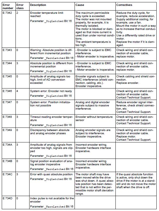
12 Typical issues that provoke the detection of E 733F The first question to answer is how frequent is the error as an indication of the possible cause. It is important to determine if the detection is constant and frequent, or whether the detection is sporadic. If it is a frequent, consistent error, it is likely linked to a hardware problem. In that case, the strategy is to trouble-shoot the different components (cable, motor, LXM32). Also very important is to verify whether there are other errors possibly associated with the detection of E 733F by analyzing the error memory in LXM32. There may be other encoder errors around, e.g., E5200 or error numbers E 73xx (see below). These additional detected errors (with additional information) can help you to find the root cause of the problem. If, for example, the data lines are interrupted after applying power, there will be E7331 and E5200: If the data lines are interrupted when drive is in RDY or RUN there is error E73211: Also there can be advisories or alerts around the errors. NOTE: Advisories and alerts are not saved in the error memory. 12
13 13
14 14

15 Encoder not connected correctly Issue: The lock of the encoder connector is not fixed. Action: Verify if the encoder connector is fixed correctly. Broken wires Issue: Some wires inside the encoder cable are broken and possibly making intermittent contact. Typically, E 733F with additional info 1 is detected. Action: Verify if the cable shows any visible signs of damage. If possible do a crosscheck (see below). Take care that the motor shaft has to be turned (either in RUN automatically or in DIS manually)! Drive 1 E733F Drive 2 No error Exchange encoder cable between Drive 1 and 2; run the motors Drive 1 No error Drive 2 E 733F Exchange encoder cable of Drive 2 with a new one 15
16 Determine if the bending radius of encoder cable is according the specification: 16


17 Damaged encoder connector drive side Issue: Cable shield was not connected to RJ 45 connector. In case the shield is not, or is incorrectly, connected, the black housing can easily be moved. Shield not connected Shield connected Action: Damaged or inadequate cables need to be replaced. Issue: The encoder connector CN3 has been broken internally. Action: To avoid this type of issue it is very important that there are no external forces or vibrations on the encoder cable and connector in the cabinet. RJ45 must be handled carefully during the wiring of the machine. NOTE: With few exceptions, there are no other user-serviceable parts within the Lexium 32. Either replace the component or contact Schneider Electric. 17


18 WARNING UNINTENDED EQUIPMENT OPERATION Do not attempt to repair this equipment outside of authorized Schneider Electric service centers. Only use software and hardware components approved by Schneider Electric for use with this equipment. Update your application program every time you change the physical hardware configuration. Failure to follow these instructions can result in death, serious injury, or equipment damage. Damaged encoder connector motor side Issue: Some pins of the encoder connector have been pushed in. This can happen if the encoder connector is not mounted correctly. Typical scenario is if the connector is not oriented correctly and forcefully screwed down. Action: Verify alignment of the connectors. Hand tighten the connectors; do not use tools. Check if the pins are still in place on the motor connector. 18
19 Shock Issue: High mechanical shocks can also provoke detection of the E 733F error. The maximum values for shock are provided in the manual: Action: Verify that any mechanical shocks are within tolerances. Electromagnetic Compatibility Issue: Error E 733F is detected sporadically. Action: In general, it is very difficult to detect if EMC disturbances are the root cause for error E 733F. However, you can reduce the risk of disturbances by validating whether the motor and drive is wired according to the Wiring Best Practices detailed in the product manuals. From BSH manual: 19

20 From LXM32 manual: 20
21 21
22 22
23 23
24 Concerning grounding the motor: Take care if the motor is only grounded via the motor flange. If there are anodized surfaces, e.g., when the motor is mounted to a gear box, ground connection continuity may be infringed or lost. In that case, use a ground strap to connect the motor with the machine. 24

25 Actions for grounding the machine: Take care that the machine is well grounded, e.g., if the machine is standing on plastic feet or other isolating material. For smaller cross sections a second ground connection should be connected. Respect your local regulations. Damaged encoder Issue: The encoder of the motor has been damaged. Action: If none of the topics above resolves the issue and only the replacement of the motor solves the issue, then the problem is linked to the motor. In that case replace it and send the suspect motor back for analysis. 25
5521 Potentiometer Analog Input Module
 55 Potentiometer Analog Input Installation, Operation and Maintenance Setup Manual 5/9/0 Safety Information The information provided in this documentation contains general descriptions and/or technical
5504 Thermocouple Analog Input Module
 550 Thermocouple Analog Input Installation, Operation and Maintenance Setup Manual 5/9/0 Safety Information The information provided in this documentation contains general descriptions and/or technical
Packaging User Guide for Temperature Control M221 Project Template
 Packaging EIO0000001762 04/2014 Packaging User Guide for Temperature Control M221 Project Template 04/2014 EIO0000001762.00 www.schneider-electric.com The information provided in this documentation contains
SoMachine Scan for Buttons Linked to ZBRN Modules Harmony ZBRN Library Guide
 SoMachine EIO0000001868 11/2016 SoMachine Scan for Buttons Linked to ZBRN Modules Harmony ZBRN Library Guide 11/2016 EIO0000001868.04 www.schneider-electric.com The information provided in this documentation
5401 and 5402 Digital I/O Modules
 50 and 50 Digital I/O Modules Installation, Operation and Maintenance Setup Manual 5/9/0 Safety Information The information provided in this documentation contains general descriptions and/or technical
SCADAPack E Idec PLC Interface Manual
 SCADAPack E Idec PLC Interface Manual 2 SCADAPack E Idec PLC Interface Manual Table of Contents Part I Idec PLC Interface 3 1 Technical... Support 3 2 Safety... Information 4 3 Preface... 6 4 Overview...
SCADAPack E Target 5 DF1 PLC Interface
 SCADAPack E Target 5 DF1 PLC Interface 2 Table of Contents Part I 3 1 Technical... Support 3 2 Safety... Information 4 3 Overview... 7 4 I/O Device... Interface 7 4.1 Input Devices... 9 4.2 Output Devices...
XPSMCMx Fieldbus Expansion Modules Instruction Sheet (Original Language)
") XPSMCMx Fieldbus Expansion Modules EAV8283001 12/2014 XPSMCMx Fieldbus Expansion Modules Instruction Sheet (Original Language) 12/2014 EAV8283001.00 www.schneider-electric.com The information provided
XPSMCMx Fieldbus Expansion Modules EAV8283001 12/2014 XPSMCMx Fieldbus Expansion Modules Instruction Sheet (Original Language) 12/2014 EAV8283001.00 www.schneider-electric.com The information provided
5403 and 5404 Digital Input Modules
 503 and 50 Digital Input Modules Installation, Operation and Maintenance Setup Manual //07 Copyright 0-07 Schneider Electric Canada Inc. All rights reserved. 503 and 50 Digital Input Modules The information
EcoStruxure Power Commission Installation Guide
 EcoStruxure Power Commission DOCA0134EN 03/2019 EcoStruxure Power Commission Installation Guide 03/2019 DOCA0134EN-04 www.schneider-electric.com The information provided in this documentation contains
Schneider Electric Floating License Manager
 Schneider Electric Floating License Manager EIO0000001078 11/2012 Schneider Electric Floating License Manager User Manual 12/2012 EIO0000001078.01 www.schneider-electric.com The information provided in
SCADAPack E 5405 Digital Input Hardware Manual
 SCADAPack E 5405 Digital Input Hardware Manual 2 SCADAPack E 5405 Digital Input Hardware Manual Table of Contents Part I 5405 Digital Input Module 3 1 Technical... Support 3 2 Safety... Information 4 3
SCADAPack E ISaGRAF Quick Start Guide
 SCADAPack E ISaGRAF Quick Start Guide 2 SCADAPack E ISaGRAF Quick Start Guide Table of Contents Part I ISaGRAF 3 Quick Start Guide 3 1 Technical... Support 3 2 Safety... Information 4 3 Preface... 6 4
SoMachine. M238 High Speed Counting Functions High_Speed_Counter_M238.project Example Guide. 04/2012 Basic. Intermediate Expert
 SoMachine M238 High Speed Counting Functions High_Speed_Counter_M238.project Example Guide 04/2012 Basic Intermediate Expert EIO0000000905.00 www.schneider-electric.com The information provided in this
Schneider Electric License Manager
 Schneider Electric License Manager EIO0000001070 11/2012 Schneider Electric License Manager User Manual 12/2012 EIO0000001070.01 www.schneider-electric.com The information provided in this documentation
Ethernet Modbus X80 Gateway Device Type Manager
 Ethernet Modbus X80 Gateway Device Type Manager EIO0000001315 10/2012 Ethernet Modbus X80 Gateway Device Type Manager User Manual 10/2012 EIO0000001315.00 www.schneider-electric.com The information provided
5502 Differential Analog Input Module
 550 Differential Analog Input Installation, Operation and Maintenance Setup Manual //07 Copyright 0-07 Schneider Electric Canada Inc. All rights reserved. 550 Differential Analog Input The information
IO-AO6X I/O Expansion Module 6 Isolated Analog Outputs
 IO-AO6X I/O Expansion Module 6 Isolated Analog Outputs The IO-AO6X is an I/O Expansion Module that can be used in conjunction with specific Unitronics OPLC controllers. The module offers 6 12-bit isolated
Momentum 170ENT11001/170ENT11002 Ethernet Communications Adapter User Guide
 Momentum 31004109 09/2017 Momentum 170ENT11001/170ENT11002 Ethernet Communications Adapter User Guide 09/2017 31004109.07 www.schneider-electric.com The information provided in this documentation contains
Unity Pro OSLoader User Manual
 Unity Pro 35006156 12/2015 Unity Pro OSLoader User Manual 12/2015 35006156.14 www.schneider-electric.com The information provided in this documentation contains general descriptions and/or technical characteristics
Acti 9 Communication System
 Acti 9 Communication System Diagnostics User Manual 05/2012 DOCA0042EN-00 www.schneider-electric.com This document contains general descriptions and/or general technical specifications of the products
LXM32AD18N4 motion servo drive - Lexium 32 - three-phase supply voltage 208/480V kw
 Characteristics motion servo drive - Lexium 32 - three-phase supply voltage 208/480V - 1.8 kw Complementary Switching frequency Overvoltage category Leakage current Output voltage Electrical isolation
V E2B Snap-in I/O Module
 i4 Automation Ltd - 01480 395256 V200-18-E2B Snap-in I/O Module The V200-18-E2B plugs directly into the back of compatible Unitronics OPLCs, creating a selfcontained PLC unit with a local I/O configuration.
SCADAPack E 5505 RTD Input Hardware Manual
 SCADAPack E 5505 RTD Input Hardware Manual 2 SCADAPack E 5505 RTD Input Hardware Manual Table of Contents Part I 5505 RTD Input Module 3 1 Technical... Support 3 2 Safety... Information 4 3 Overview...
SCADA Expert Vijeo Citect Architecture and Redundancy Study Guide
 SCADA Expert Vijeo Citect Architecture and Redundancy Study Guide 2015 Schneider-Electric Pty (Australia) Ltd 78 Waterloo Road Macquarie Park NSW 2113 Australia DISCLAIMER Schneider Electric makes no representations
SoMachine V3.0. Modbus TCP Communications Modbus_TCP.project Example Guide. 04/2011 Basic. Intermediate Expert.
 SoMachine V3.0 Modbus TCP Communications Modbus_TCP.project Example Guide 04/2011 Basic Intermediate Expert EIO0000000919.00 www.schneider-electric.com The information provided in this documentation contains
RMCN22BD Analog Converter ma - for Zelio Analog
 Characteristics Analog Converter - 4..20 ma - for Zelio Analog Main Commercial Status Range of product Product or component type Analogue input type Analogue output type Commercialised Zelio Analog Voltage/Current
Schneider Electric AB DH485 Protocol XBT N/R/RT
 Schneider Electric AB DH485 Protocol XBT N/R/RT 33004016 06/2008 33004016.01 2 33004016 06/2008 Table of Contents Safety Information....................................5 About the Book.......................................7
SCADA Expert Vijeo Citect 2015 Programming with Cicode Study Guide
 SCADA Expert Vijeo Citect 2015 Programming with Cicode Study Guide 2015 Schneider-Electric Pty (Australia) Ltd 78 Waterloo Road Macquarie Park NSW 2113 Australia DISCLAIMER Schneider Electric makes no
File Synchronization User Guide
 Eurotherm PAC User Guide Issue 2 April 2018 HA033151/2 Legal Information The information provided in this documentation contains general descriptions and/or technical characteristics of the performance
SCADAPack Input/Output Module Hardware Manual. Version: February 2016
 SCADAPack Version: Date: February 2016 Table of Contents 1 Legal Information...6 2 Technical Support...7 3 Safety Information...8 4 Documentation...11 Check 5 About this Manual...13 6 About the 5607 I/O
PacDrive Logic Motion Controller LMC Pro/Pro2 Hardware Guide
 PacDrive Logic Motion Controller EIO0000001503 03/2016 PacDrive Logic Motion Controller LMC Pro/Pro2 Hardware Guide (Original Document) 03/2016 EIO0000001503.02 www.schneider-electric.com The information
TeSys UASILUFC5 - ASILUFC51 AS-i Communication Module
 1639093 03/2009 TeSys UASILUFC5 - ASILUFC51 AS-i Communication Module User Manual 03/2009 1639093 www.schneider-electric.com Schneider Electric assumes no responsibility for any errors that may appear
RELEASE NOTES. WSOS5 version 5.16.xx. Version Schneider Electric. All Rights Reserved.
 RELEASE NOTES WSOS5 version 5.16.xx Version 02 2017 Schneider Electric. All Rights Reserved. Page 1 of 14 The information provided in this documentation contains general descriptions and/or technical characteristics
V E1B Snap-in I/O Module
 V200-18-E1B Snap-in I/O Module The V200-18-E1B plugs directly into the back of compatible Unitronics OPLCs, creating a selfcontained PLC unit with a local I/O configuration. Features 16 isolated digital
How Can I. Integrate a Third-Party Modbus Device with PowerSCADA Expert? System Technical Note PowerSCADA Expert V1.0
 How Can I Integrate a Third-Party Modbus Device with PowerSCADA Expert? System Technical Note PowerSCADA Expert V1.0 Safety Information Important Information Read these instructions carefully before trying
5910 Ethernet Gateway Module
 Hardware Manual 2/24/2017 Copyright 2014-2017 Schneider Electric Canada Inc. All rights reserved. 5910 Ethernet Gateway Module The information provided in this documentation contains general descriptions
Model P4017 Single Channel USB Oscilloscope. Quick Start Guide
 Model P4017 Single Channel USB Oscilloscope Quick Start Guide General Warranty BNC warrants that the product will be free from defects in materials and workmanship for 3 years from the date of purchase
IO-DI8-TO8, IO-DI8-TO8-L I/O Expansion Modules 8 Inputs, 8 Outputs
 IO-DI8-TO8, IO-DI8-TO8-L I/O Expansion Modules 8 Inputs, 8 Outputs The IO-DI8-TO8 and IO-DI8-TO8-L are I/O expansion modules that can be used in conjunction with specific Unitronics OPLC controllers. The
SCADAPack E ISaGRAF 3 I/O Connection Reference
 SCADAPack E ISaGRAF 3 I/O Connection Reference 2 SCADAPack E ISaGRAF 3 I/O Connection Reference Table of Contents Part I ISaGRAF 3 I/O Connection 4 1 Technical... Support 4 2 Safety... Information 5 3
Operating instructions. Speed monitor D / / 2014
 Operating instructions Speed monitor D200 80005257 / 00 05 / 2014 Contents 1 Preliminary note...4 1.1 Symbols used...4 1.2 Warning signs used...4 2 Safety instructions...5 2.1 General...5 2.2 Target group...5
User s Manual Pulse Encoder Interface Module OTAC-01
 Drive IT Low Voltage AC Drives User s Manual Pulse Encoder Interface Module OTAC-01 2 Safety WARNING! All electrical installation and maintenance work on the drive should be carried out by qualified electricians
IO-PT4. Component identification. User safety and equipment protection guidelines. Unitronics Industrial Automation Systems 1
 IO-PT4 I/O Expansion Module 4 PT100 Inputs (-50 to 460 C) The IO-PT4 is an I/O expansion module that can be used in conjunction with specific Unitronics OPLC controllers. The module offers 4 PT100 inputs
BTL6-A_10-M -A1-S115. Data Sheet. english
 BT6-A_10-M -A1-S11 english Data Sheet Balluff GmbH Schurwaldstrasse 9 76 Neuhausen a.d.f. Germany Phone +49 (0) 71 8/1-0 Fax +49 (0) 71 8/0 10 Servicehotline +49 (0) 71 8/1-70 E-Mail: balluff@balluff.de
ABL4RSM24050 regulated SMPS - 1 or 2 phase V AC - 24 V - 5A
 Characteristics regulated SMPS - 1 or 2 phase - 120..230 V AC - 24 V - 5A Complementary Input voltage limits Network frequency Inrush current Main Range of product Product or component type Power supply
ABL8BBU24200 battery control module V DC - 24 V - 20 A - for regulated SMPS
 Characteristics battery control module - 24..28.8 V DC - 24 V - 20 A - for regulated SMPS Main Range of product Product or component type Input voltage Output voltage Maximum output current Phaseo Battery
SCADAPack E Koyo DirectNET PLC Interface Manual
 SCADAPack E Koyo DirectNET PLC Interface Manual 2 SCADAPack E Koyo DirectNET PLC Interface Manual Table of Contents Part I Koyo DirectNET PLC Interface 3 1 Technical... Support 3 2 Safety... Information
Resolver to Digital Expansion Board
 Resolver to Digital Expansion Board Catalog No. EXB009A01 Installation and Operating Manual 6/98 MN1313 Table of Contents Section 1 General Information............................. 1-1 Introduction....................................
Operating instructions. Switching amplifier DN0210 DN / / 2015
 Operating instructions Switching amplifier DN0210 DN0220 UK 80011079 / 00 01 / 2015 Contents 1 Preliminary note...4 1.1 Symbols used...4 1.2 Warning signs used...4 2 Safety instructions...5 2.1 General...5
Installation manual Digital Energy USB / RS232 / Relay Interface Card for use with GE Digital Energy VH Series UPS VA
 GE Consumer & Industrial Installation manual Digital Energy USB / RS232 / Relay Interface Card for use with GE Digital Energy VH Series UPS 700-3000 VA GE Consumer & Industrial SA General Electric Company
SCADAPack E Input/Output Module Hardware Manual. Version: Date: August 2017
 SCADAPack E Version: Date: August 2017 Table of Contents 1 Legal Information...5 2 Technical Support...6 3 Safety Information...7 4 Documentation Check...10 5 About this Manual...11 6 About the 5610 I/O
5607 Input/Output (I/O) Module
 Module") 5607 Input/Output (I/O) Module Installation, Operation and Maintenance Setup Manual 5/19/2011 Safety Information The information provided in this documentation contains general descriptions and/or technical
5607 Input/Output (I/O) Module Installation, Operation and Maintenance Setup Manual 5/19/2011 Safety Information The information provided in this documentation contains general descriptions and/or technical
EX-RC1 Remote I/O Adapter
 EX-RC1 Remote I/O Adapter The EX-RC1 interfaces between Unitronics Vision OPLCs and remote I/O Expansion Modules distributed throughout your system. The adapter is connected to a PLC via CANbus. Each adapter
TM7BDI16B. Main. Enclosure material. Input/output number 16 Input/output number of splitter box
 Product datasheet Characteristics TM7BDI16B Main Range of product Product or component type Range compatibility Enclosure material Bus type System Voltage Input/output number 16 Input/output number of
Altivar - Lexium. Option modules DANGER S1A S1A /8 VW3A3601 / VW3A3608 VW3A3616 / VW3A3627 VW3A3619 VW3A3720 VW3A3721 VW3M3308
 S1A4559106 Option modules Altivar - Lexium 01 / 08 16 / 27 19 09 28 3725 3M3301 07 18 3720 3721 3M3308 HAZARD OF ELECTRIC SHOCK, EXPLOSION, OR ARC FLASH DANGER Only appropriately trained persons who are
Security Quick Start Guide
 2 Table of Contents Part I 4 1 Technical... Support 4 2 Safety... Information 5 3 Introduction... 7 4 Security... Overview 8 5 How to... Configure DNP3 Secure Authentication 11 5.1 Check RTU Firm... w
IO-DI8-TO8 I/O Expansion Module 8 Inputs, 8 Outputs
 IO-DI8-TO8 I/O Expansion Module 8 Inputs, 8 Outputs The IO-DI8-TO8 is an I/O expansion module that can be used in conjunction with specific Unitronics OPLC controllers. The module offers 8 digital inputs,
Manual Version: V1.00. Video Decoder Quick Guide
 Manual Version: V1.00 Video Decoder Quick Guide Thank you for purchasing our product. If there are any questions, or requests, please do not hesitate to contact the dealer. Copyright Copyright 2016 Zhejiang
SCADAPack E Input/Output Module Hardware Manual. Version: March 2016
 SCADAPack E Version: Date: March 2016 Table of Contents 1 Legal Information...6 2 Technical Support...7 3 Safety Information...8 4 Documentation...11 Check 5 About this Manual...13 6 About the 5606 I/O
Multi-Loader. User manual 06/ BBV48778
 Multi-Loader User manual 06/2009 BBV48778 www.schneider-electric.com Contents Important information 4 Before you begin 5 Documentation structure 6 Setup procedure 7 Introduction 8 Receipt of the Multi-Loader
Vijeo Citect Customization and Design Study Guide
 Vijeo Citect Customization and Design Study Guide Version 7.30 Schneider-Electric Pty (Australia) Ltd 78 Waterloo Road Macquarie Park NSW 2113 Australia DISCLAIMER Schneider Electric makes no representations
DVI Extender over Fiber with EMI Shielding
 DVI Extender over Fiber with EMI Shielding Model #: FO-DVI-1000M-EMI 2010 Avenview Inc. All rights reserved. The contents of this document are provided in connection with Avenview Inc. ( Avenview ) products.
Digital encoder interface module 5/12/24 V DANGER
 NHA807300 Digital encoder interface module 5//4 V VW3A340 DANGER HAZARD F ELECTRIC SHCK, EXPLSIN, R ARC FLASH nly appropriately trained persons who are familiar with and understand the contents of this
RM17TG. Main. Product or component type. Product specific application. Relay monitored parameters. Switching capacity in VA
 Characteristics phase control relay RM17-T - range 183..484 V AC Main Range of product Product or component type Relay type Product specific application Relay name Relay monitored parameters Switching
PV Rapid Shutdown device
 PV Rapid Shutdown device Installation and Operation Manual Solis-RSD-1G(1:1) Solis-RSD-1G(2:2) Manufacturer: Ginlong (Ningbo) Technologies Co.,Ltd., Ningbo, Zhejiang, P.R.China US Office: 565 Metro Pl.
SINAMICS G130. Voltage Sensing Module 10 (VSM10) Operating Instructions 05/2010 SINAMICS
 Operating Instructions 05/2010 SINAMICS") SINAMICS G130 Operating Instructions 05/2010 SINAMICS s Safety information 1 General 2 SINAMICS SINAMICS G130 Voltage Sensing Module 10 (VSM10) Mechanical installation 3 Electrical installation 4 Technical
SINAMICS G130 Operating Instructions 05/2010 SINAMICS s Safety information 1 General 2 SINAMICS SINAMICS G130 Voltage Sensing Module 10 (VSM10) Mechanical installation 3 Electrical installation 4 Technical
When any of the following symbols appear, read the associated information carefully. Symbol Meaning Description
 Uni-I/O Modules Installation Guide UID-0808THS Uni-I/O is a family of Input/Output modules that are compatible with the UniStream control platform. This guide provides basic installation information for
SINAMICS G130. Terminal Module 150 (TM150) Operating Instructions 03/2013 SINAMICS
 Operating Instructions 03/2013 SINAMICS") SINAMICS G130 Operating Instructions 03/2013 SINAMICS s Safety information 1 General information 2 SINAMICS SINAMICS G130 Mechanical installation 3 Electrical installation 4 Technical specifications 5
SINAMICS G130 Operating Instructions 03/2013 SINAMICS s Safety information 1 General information 2 SINAMICS SINAMICS G130 Mechanical installation 3 Electrical installation 4 Technical specifications 5
Unity Loader A SoCollaborative Software User Manual
 Unity Loader 33003805 02/2017 Unity Loader A SoCollaborative Software User Manual 02/2017 33003805.11 www.schneider-electric.com The information provided in this documentation contains general descriptions
MDM 011-Z1 Regen Resistor
 MDM 011-Z1 Regen Resistor Date of creation: 10.04.2017 Version date: 10.04.2017 Article number: 09-402-011-Z1-E Publisher: SIGMATEK GmbH & Co KG A-5112 Lamprechtshausen Tel.: 06274/4321 Fax: 06274/4321-18
BCM ULP Breaker Communication Module
 DOCA0152EN-00 BCM ULP Breaker Communication Module Firmware Version 4.1.9 Release Note 05/2018 The information provided in this documentation contains general descriptions and/or technical characteristics
Modicon M340 for Ethernet Communications Modules and Processors User Manual
 Modicon M340 for Ethernet 31007131 12/2018 Modicon M340 for Ethernet Communications Modules and Processors User Manual (Original Document) 12/2018 31007131.16 www.schneider-electric.com The information
RM17TG. Main. Product or component type. Product specific application. Relay monitored parameters. Switching capacity in VA 250 V AC
 Characteristics phase control relay RM17-T - range 183..484 V AC Complementary Maximum switching voltage Minimum switching current [Us] rated supply voltage Supply voltage limits Control circuit voltage
ABL8REM24050 regulated SMPS - 1 or 2-phase V AC - 24 V - 5 A
 Characteristics regulated SMPS - 1 or 2-phase - 100..240 V AC - 24 V - 5 A Complementary Input voltage limits Network frequency Inrush current Main Range of product Product or component type Power supply
I/O Expansion Box Installation & Operator s Instruction Manual
 I/O Expansion Box Installation & Operator s Instruction Manual May 2004 CTB Inc. Warranty I/O Expansion Box CTB Inc. Warranty CTB Inc. warrants each new Chore-Tronics product manufactured by it to be free
INSTRUCTION MANUAL DISTRIBUTION UNIT. Please read this manual thoroughly before use, and keep it handy for future reference.
 INSTRUCTION MANUAL DISTRIBUTION UNIT Please read this manual thoroughly before use, and keep it handy for future reference. ISSUE 1 May 2006 LIMITATION OF LIABILITY THE INFORMATION IN THIS PUBLICATION
SoMachine HVAC v2.2. Release Notes
 Software / Firmware Version: SoMachine HVAC v2.2 Release Notes TM171PDM27 PV: 01, RL: 04 SV: 423.24 TM171PBM27R PV: 01, RL: 04 SV: 477.24 TM171PFE03 PV: 01, RL: 04 SV: 489.17 TM171DGRP PV: 01, RL: 04 SV:
V E2B Snap-in I/O Module
 V200-18-E2B Snap-in I/O Module The V200-18-E2B plugs directly into the back of compatible Unitronics OPLCs, creating a selfcontained PLC unit with a local I/O configuration. Features 16 isolated digital
It's Here... Access Elevator Supply now offers Replacement Logic Boards for Siemens Class 72G Elevator Soft Starters. Easy to install and lightweight
 It's Here... Access Elevator Supply now offers Replacement Logic Boards for Siemens Class 72G Elevator Soft Starters. Easy to install and lightweight to ship, these logic boards are a convenient solution
GETTING STARTED GUIDE NI V, 32-Channel (Sinking Input), 7 µs C Series Digital Module
, 7 µs C Series Digital Module") GETTING STARTED GUIDE NI 9425 24 V, 32-Channel (Sinking Input), 7 µs C Series Digital Module This document explains how to connect to the NI 9425. In this document, the NI 9425 with spring terminal and
GETTING STARTED GUIDE NI 9425 24 V, 32-Channel (Sinking Input), 7 µs C Series Digital Module This document explains how to connect to the NI 9425. In this document, the NI 9425 with spring terminal and
Component identification
 IO-ATC8 I/O Expansion Module 8 Analog/Thermocouple Inputs The IO-ATC8 is an I/O Expansion Module that can be used in conjunction with specific Unitronics OPLC controllers. The module offers 8 inputs that
Rhino Redundancy Module PSM24-REM360S. Operating Instructions
 Rhino Redundancy Module PSM4-REM360S Operating Instructions RHINO REDUNDANCY MODULE PSM4-REM360S Description With this module and two power supplies of the PSM series (78, 90, 56, 80 and 360 watt models),
Pro-face Connect Troubleshooting for SiteManager (Access to GateManager)
") Pro-face Connect Troubleshooting for SiteManager (Access to GateManager) Preface The information provided in this documentation contains general descriptions and/or technical characteristics of the performance
Pro-face Connect Troubleshooting for SiteManager (Access to GateManager) Preface The information provided in this documentation contains general descriptions and/or technical characteristics of the performance
Install Motor Controller User Manual
 Property of Motion Laboratories, Inc. Install Motor Controller User Manual 2014 Motion Laboratories, Inc. Created By: Michael Shaw Approved By: John Coppolecchia Page: 1 Page: 2 2014 Motion Laboratories,
Wa r n i n g-wa r n i n g-wa r n i n g
 Installation Instructions of the Power Analyzer Wa r n i n g-wa r n i n g-wa r n i n g Read and understand this manual before connecting device. Death, fire or serious injury can occur from using equipment
LINE VOLTAGE TESTER CT101 USER S MANUAL. Please read this manual carefully and thoroughly before using this product.
 LINE VOLTAGE TESTER USER S MANUAL CT101 Please read this manual carefully and thoroughly before using this product. KEY FEATURES Visual indication of AC or DC voltage Easy to use approved Safe for CAT
CrystalView DVI Multi INSTALLATION AND OPERATIONS MANUAL Stancliff Road Phone: (281)
") CrystalView DVI Multi INSTALLATION AND OPERATIONS MANUAL 10707 Stancliff Road Phone: (281) 933-7673 Houston, Texas 77099 WWW.ROSE.COM LIMITED WARRANTY Rose Electronics warrants the CrystalView Multi to
CrystalView DVI Multi INSTALLATION AND OPERATIONS MANUAL 10707 Stancliff Road Phone: (281) 933-7673 Houston, Texas 77099 WWW.ROSE.COM LIMITED WARRANTY Rose Electronics warrants the CrystalView Multi to
Demo Kit Quick Start Guide
 Near Field Imaging (NFI) Projected Capacitive Touch Screen Systems Read and understand all safety information contained in this document before using this product. Introduction This is intended to help
Twido Programmable Controllers Discrete I/O Modules
 Twido Programmable Controllers Discrete I/O Modules Hardware Guide 03/2007 www.telemecanique.com 2 Table of Contents Safety Information....................................5 About the Book.......................................9
Modicon TM3 (SoMachine Basic) Expansion Modules Configuration Programming Guide
 Expansion Modules Configuration Programming Guide") Modicon TM3 (SoMachine Basic) EIO0000001396 12/2015 Modicon TM3 (SoMachine Basic) Expansion Modules Configuration Programming Guide 12/2015 EIO0000001396.05 www.schneider-electric.com The information provided
Modicon TM3 (SoMachine Basic) EIO0000001396 12/2015 Modicon TM3 (SoMachine Basic) Expansion Modules Configuration Programming Guide 12/2015 EIO0000001396.05 www.schneider-electric.com The information provided
SINAMICS G130. Voltage Sensing Module 10 (VSM10) Operating instructions 03/2011 SINAMICS
 Operating instructions 03/2011 SINAMICS") SINAMICS G130 Operating instructions 03/2011 SINAMICS s Safety information 1 General 2 SINAMICS SINAMICS G130 Voltage Sensing Module 10 (VSM10) Mechanical installation 3 Electrical installation 4 Technical
SINAMICS G130 Operating instructions 03/2011 SINAMICS s Safety information 1 General 2 SINAMICS SINAMICS G130 Voltage Sensing Module 10 (VSM10) Mechanical installation 3 Electrical installation 4 Technical
ATS22C17Q. Main. Range of product Altistart 22. Component name. Factory setting current. Utilisation category. IP degree of protection
 Product datasheet Characteristics ATS22C17Q Complementary Assembly style Function available Supply voltage limits Main Range of product Altistart 22 Product or component type Product destination Product
SAFETY, ENVIRONMENTAL, AND REGULATORY INFORMATION. NI CompactDAQ Four-Slot Controller with Quad-Core Processor
 SAFETY, ENVIRONMENTAL, AND REGULATORY INFORMATION NI cdaq -9136 NI CompactDAQ Four-Slot Controller with Quad-Core Processor This document includes compliance precautions and connection information for
The identified danger could cause physical and property damage.
 Samba OPLC SM35-J-T20 Installation Guide The Unitronics SM35-J-T20 offers the following onboard I/Os: 12 Digital Inputs, configurable via wiring to include 2 Analog and 3 HSC/Shaft-encoder Inputs 8 Transistor
ABL1REM24100 regulated SMPS - single phase V input - 24 V output W
 Characteristics regulated SMPS - single phase - 100..240 V input - 24 V output - 240 W Complementary Input voltage limits Network frequency limits Inrush current Main Range of product Product or component
ATS22C41Q soft starter-ats22-control 220V-power 230V(110kW)/ V(220kW)
/ V(220kW)") Characteristics soft starter-ats22-control 220V-power 230V(110kW)/400...440V(220kW) Complementary Assembly style Function available Power supply voltage limits Main Range of product Altistart 22 Product
Characteristics soft starter-ats22-control 220V-power 230V(110kW)/400...440V(220kW) Complementary Assembly style Function available Power supply voltage limits Main Range of product Altistart 22 Product
ATS22D47S6U. Main. Range of product Altistart 22. Component name. Factory setting current. Utilisation category. IP degree of protection
 Product datasheet Characteristics ATS22D47S6U Complementary Assembly style Function available Supply voltage limits Main Range of product Altistart 22 Product or component type Product destination Product
USER MANUAL. MODEL 552 Series. High Speed Telco Surge Protectors. SALES OFFICE (301) TECHNICAL SUPPORT (301)
 TECHNICAL SUPPORT (301)") USER MANUAL MODEL 552 Series High Speed Telco Surge Protectors C E R T I F I E D An ISO-9001 Certified Company Part# 07M552-E Rev. G Revised 01/27/10 SALES OFFICE (301) 975-1000 TECHNICAL SUPPORT (301)
USER MANUAL MODEL 552 Series High Speed Telco Surge Protectors C E R T I F I E D An ISO-9001 Certified Company Part# 07M552-E Rev. G Revised 01/27/10 SALES OFFICE (301) 975-1000 TECHNICAL SUPPORT (301)
3-Phase, Dual-Input 6-Slot Power Supply System STARTUP GUIDE
 3-Phase, Dual-Input 6-Slot Power Supply System STARTUP GUIDE -ST-01 Page 1 of 10 November 2016 2016 Copyright Lite-On Technology Corporation ALL RIGHTS RESERVED. Lite-On is a trademark of Lite-On Technology
Diagnostic communication setup with MB/TCP and E/IP fieldbus modules FW 1.7 or 1.8
 Diagnostic communication setup with MB/TCP and E/IP fieldbus modules FW 1.7 or 1.8 Application Technical note Author: Matti Haliseva, Schneider Electric, Machine Solutions Page 1 of 20 The information