Scanning Instrument Operation Manual
|
|
|
- Rudolf Warren
- 6 years ago
- Views:
Transcription

1 Scanning Instrument Operation Manual
2
3 Dear Customer: Congratulations! We at X-Rite, Incorporated are proud to present you with an X-RiteColor Spectrofiler Scanning Instrument. This system represents the very latest in microcontrollers, integrated circuits, optics, and software design. As a result, your X-RiteColor Spectrofiler is a rugged and reliable instrument whose performance and design are not surpassed. To fully appreciate and protect your investment, we suggest that you take the necessary time to read and fully understand this manual. As always, X-Rite stands behind your system with a one year limited warranty, and a dedicated service organization. If the need arises, please don t hesitate to call us. Thank you for your trust and confidence. X-Rite, Incorporated
4
5 I N T R O D U C T I O N User Information FCC This equipment has been tested and found to comply with the limits for a Class A digital device, pursuant to Part 15 of the FCC Rules. These limits are designed to provide reasonable protection against harmful interference when the equipment is operated in a commercial environment. This equipment generates, uses, and can radiate radio frequency energy and, if not installed and used in accordance with the instruction manual, may cause harmful interference to radio communications. Operation of this equipment in a residential area is likely to cause harmful interference in which case the user will be required to correct the interference at his own expense. Canada This Class A digital apparatus meets all requirements of the Canadian Interference- Causing Equipment Regulations. Cet appareil numérique de la classe A respecte toutes les exigences du Règlement sur le matériel brouilleur du Canada. NOTE: Shielded interface cables must be used in order to maintain compliance with the desired FCC and European emission requirements. Keep Cal Plaques Clean At All Times. Kalibrierstandards sauberhalten! Siempre mantenga la placa de calibración limpia. Tenir le plaque de calibration propre tout le temps. Sempre mantenga la placca della calibrazione pulita. i
6 I N T R O D U C T I O N Do Not Oil Moving Parts. Bewegliche Teile nicht ölen! No lubrifique las peizas en movimiento Ne pas lubrifier les pièces en mouvement Non lubrificare le parti mobili. CAUTION: Use only the 24v Adapter (P/N ATS40-109) to supply power to the Docking Station. BENUTZEN Sie nur das X-Rite 24V Netzteil P/N ATS für die Docking Station. ADVERTENCIA: Use solamente el Adaptador de 24v (pieza Nº ATS40-109) para suministrar la energía al mecanismo de conexión. AVERTISSEMENT: Utiliser seulement l adaptateur de 24v (P/N ATS40-109) pour fournir l alimentation au mécanisme de connexion. AVVERTIMENTO: Usare solamente l adattatore di 24v (parte n. ATS40-109) per fornire l alimentazione al meccanismo del collegamento. The Manufacturer: Der Hersteller: El fabricante: Le fabricant: Il fabbricante: Declares that: gibt bekannt: advierte que: avertit que: avverte che: X-Rite, Incorporated Auto Tracking Spectrophotometer ATS is not intended to be connected to a public telecommunications network. an ein öffentliches Telekommunikations-Netzwerk nicht angeschlossen werden soll. no debe ser conectado a redes de telecomunicaciones públicas. ne doit pas être relié à un réseau de télécommunication publique. non deve essere connettuto a reti di telecomunicazioni pubblici. ii
7 I N T R O D U C T I O N CE DECLARATION Manufacturer's Name: Authorized Representative: X-Rite, Incorporated X-Rite, Incorporated Siemensstraße 12b Neu-Isenburg Germany Phone: +49 (0) Fax: +49 (0) Model Name: Model No.: Directive(s) Conformance: Auto Tracking Spectrophotometer ATS EMC 89/336/EEC LVD 73/23/EEC, 93/68/EEC iii
8 I N T R O D U C T I O N PROPRIETARY NOTICE The information contained in this manual is derived from patent and proprietary data of X-Rite, Incorporated. This manual has been prepared solely for the purpose of assisting in the use and general maintenance of this instrument. The contents of this manual are the property of X-Rite, Incorporated and are copyrighted. Any reproduction in whole or part is strictly prohibited. Publication of this information does not imply any rights to reproduce or use this manual for any purpose other than installing, operating, or maintaining this instrument. No part of this manual may be reproduced, transcribed, transmitted, stored in a retrieval system, or translated into any language or computer language, in any form or by any means, electronic, magnetic, mechanical, optical, manual, or otherwise, without the prior written permission of an officer of X-Rite, Incorporated. Copyright 2007 by X-Rite, Incorporated ALL RIGHTS RESERVED X-Rite, X-RiteColor and the X-RiteColor logo are registered trademarks of X-Rite, Incorporated All other logos, product names, and trademarks mentioned are the property of their respective holders. iv
9 I N T R O D U C T I O N LIMITED WARRANTY X-Rite, Incorporated ( X-Rite ) warrants each instrument manufactured to be free of defects in material and workmanship (excluding battery pack) for a period of 12 months. This warranty shall be fulfilled by the repair or replacement, at the option of X-Rite, of any part or parts, free of charge including labor, F.O.B. its factory or authorized service center. This warranty shall be voided by any repair, alteration, or modification, by persons other than employees of X-Rite, or those expressly authorized by X- Rite to perform repairs, and by any abuse, misuse, or neglect of the product, or by use not in accordance with X-Rite s published instructions. X-Rite reserves the right to make changes in design and /or improvements to its products without any obligation to include these changes in any products previously manufactured. Correction of defects by repair or replacement shall constitute fulfillment of all warranty obligations on the part of X-Rite. THIS WARRANTY IS EXPLICITLY IN LIEU OF ANY OTHER EXPRESSED OR IMPLIED WARRANTIES, INCLUDING ANY IMPLIED WARRANTY OF MERCHANTABILITY OR FITNESS FOR ANY PARTICULAR PURPOSE. THIS WARRANTY OBLIGATION IS LIMITED TO REPAIR OR REPLACEMENT OF THE UNIT RETURNED TO X-RITE OR AN AUTHORIZED SERVICE CENTER FOR THAT PURPOSE. This agreement shall be interpreted in accordance with the laws of the State of Michigan and jurisdiction and venue shall lie with the courts of Michigan as selected by X-Rite, Incorporated. v
10 I N T R O D U C T I O N INSTRUMENT TRACEABILITY The spectral reflectance values for the supplied white reference are traceable to the National Institute of Standards and Technology through the RIT Munsell Color Laboratory. The RIT Laboratory maintains standards to which NIST assigned values. These standards were used in assigning values to X-Rite s two primary standard white porcelain on steel plaques. A calibration report (MCSL-18) issued by Munsell Color Science Laboratory contains measurement methods, measurement values, and verifies the ceramic plaques NIST traceability path. These two plaques are used to generate the supplied white reference. ABOUT THIS MANUAL This document covers the installation, operation, calibration, and general maintenance of your X-RiteColor Spectrofiler Scanning Instrument. Refer to your X-RiteColor Spectrofiler software documentation for complete software installation and operation instructions. This manual is organized into four sections and two appendices. In order to make the best use of your system, it is recommended that you read all sections and appendices. vi
11 I N T R O D U C T I O N Table of Contents SECTION ONE Installing the System Unpacking and Inspection Packaging Drawing and Parts List System Description Track and Docking Station Scanning Head Vacuum Pump Installing the Scanning Head System Connections Vacuum Pump Connections RS-232 Interface Connection Connecting Power SECTION TWO Operating the System Calibrating the Scanning Instrument Positioning a Target on the Instrument Taking a Measurement with the Scanning Instrument SECTION THREE General Maintenance Repair Information Cleaning the System General Cleaning Cleaning the Instrument Calibration References SECTION FOUR Troubleshooting Tips APPENDIX A Technical Specifications... A-1 APPENDIX B Parts List and Packaging Drawing... B-1 vii
12 I N T R O D U C T I O N viii
13 S E C T I O N O N E Installing the System This section covers unpacking, inspection, and installation of your system. System description and vocabulary illustrations are also included. You should read through this entire section to familiarize yourself with your instrument. Section Contents Unpacking and Inspection System Description Installing the Scanning Head System Connections UNPACKING AND INSPECTION The main system components are packaged separately: Track/Docking Station, Scanning Head, Cabling, Documentation, and Accessories Software Vacuum Pump After removing the components from each shipping carton, inspect them for damage. If any damage has occurred during shipping, immediately contact the transportation company that shipped them. Do not proceed with installation until the carrier s agent has inspected the damage. Your components were packaged in specially-designed cartons to help prevent damage. If reshipment is necessary, the components should be packaged in the original carton. If the original carton is not available, contact X-Rite to have replacements shipped to you. Packaging Drawings and Parts Lists Check your package contents against your packing list and original order. A detailed packaging drawing and parts list is included in this manual as Appendix B. 1-1
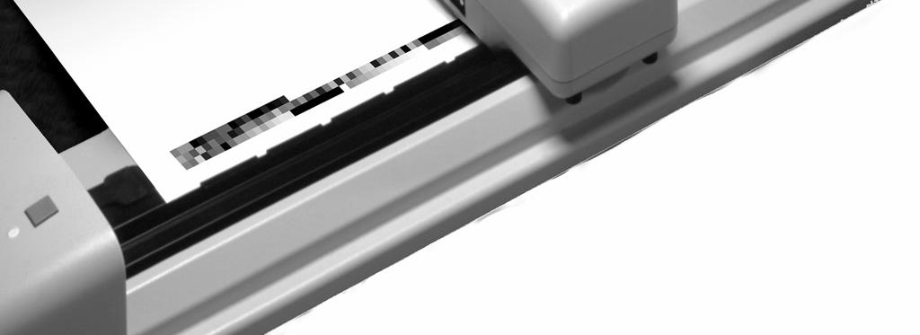
14 S E C T I O N O N E SYSTEM DESCRIPTION The X-RiteColor Spectrofiler is the fastest and most advanced color measurement scanning instrument, designed to automate laboratory collection of color measurement data. Its features include the ability to quickly measure complex, printed test images and report a variety of measurement data with flexible formatting. The instrument is a true 31-point spectrophotometer that uses X-Rite s proprietary DRS spectral engine technology, and whose data matches that of the industry standard, X-Rite 900 Series Spectrophotometer. Vacuum Pump Docking Station Indicator Lamp Operation Button Scanning Head Measurement Track 1-2
15 I N S T A L L I N G T H E S Y S T E M Track and Docking Station The test target is held securely to the track through a series of vacuum holes while the Scanning Head measures the patches. The Operation button is used to activate a measurement sequence. The indicator light on the Docking Station will illuminate three separate colors for varies mode conditions: Solid Green Light indicates that the scanning head is docked and ready for use. Solid Yellow Light indicates that the scanning head is away from the docking station. Solid Red Light indicates that an error or problem exists with the System. Flashing Yellow Light indicates unit powered up to take reading. Flashing Red Light indicates there is a problem and unit needs service. Flashing Yellow & Green indicates System needs to be reset. Reset is performed by pressing and holding Operation button for 5-seconds. Operation Button Indicator Lamp Vacuum Holes System Connections 1-3
16 S E C T I O N O N E Scanning Head The scanning head is a 31-point, 45 /0 device which scans a spectral range of nanometers. The scanning head has a 1.5 x 3.5mm scan spot that has 0.2DE repeatability on white. Vacuum Pump A series of small holes located in the surface of the Track are used to hold the test image in place during a measurement. This is accomplished by the use of a Vacuum Pump. The Vacuum Pump is connected to the Docking Station allowing automatic activation during a measurement cycle. Interconnect Box Vacuum Inlet Port 1-4
17 I N S T A L L I N G T H E S Y S T E M INSTALLING THE SCANNING HEAD If the Scanning Head is removed, follow the procedure below to reattach it to the Trolley. 1. Position the Scanning Head Trolley approximately 12 inches from the Docking Station. This is accomplished by sliding the Trolley away from the Docking Station with your hand. 2. Position the Scanning Head over the Trolley and slide forward allowing the Holding Disks to insert into the Scanning Head. 3. Align the Trolley Thumbscrews with the Posts and Post Holes in the Scanning Head. 4. Loosely secure the thumbscrews to the Scanning Head. Alternately tighten until firmly seated. NOTE: Scanning Head must be securely fastened to Trolley to allow proper operation of instrument. Scanning Head Posts Holding Disks Head Connector Post Hole Docking Station Trolley Thumbscrew 1-5
18 S E C T I O N O N E SYSTEM CONNECTIONS The System requires a few simple connections before operating. Connection procedures for the individual components are covered on the following pages. Back of Docking Station Power Input Vacuum Pump I/O Port Computer I/O Port Vacuum Pump Hose Connection Vacuum Pump Connections 1. Push one end of Vacuum Hose onto the Barbed Adapter at back of the Docking Station. 2. Push other end of Vacuum Hose onto the Barbed Adapter on Vacuum Pump. NOTE: To obtain up to 15% more vacuum from the pump, remove the exhaust port barbed adapter. Docking Station IN OUT Vacuum Hose Exhaust Port 1-6
19 I N S T A L L I N G T H E S Y S T E M 3. Make sure the Voltage Selection Switch located below Line Cord Receptacle has been set to the proper line voltage for your region. 4. Connect one end of I/O Interface Cable to Vacuum Pump I/O Port on the Docking Station. 5. Connect other end of I/O Interface Cable to an I/O Port on the Vacuum Pump Connect Box (either port can be used). 6. Connect the Line Cord to the Vacuum Pump AC Cord Receptacle. 7. Plug Line Cord into AC wall receptacle. NOTE: Vacuum Pump will only operate during a measurement sequence. Vacuum Pump I/O Port I/O Interface Cable I/O Port Vacuum Pump Connect Box To AC Wall Receptacle Line Cord Voltage Selection Switch AC Cord Receptacle 1-7
20 S E C T I O N O N E RS-232 Interface Connection 1. Connect one end of the DB-9 Interface Cable to an available Serial Port on back of your computer. Secure with thumbscrews. 2. Connect opposite end of DB-9 Interface Cable to Serial I/O Port on back of Docking Station. Secure with Thumbscrews. Computer Serial I/O Port Thumbscrews DB-9 Interface Cable Serial I/O Port Thumbscrews 1-8
21 I N S T A L L I N G T H E S Y S T E M Connecting Power The scanning instrument must be allowed to stabilize at room temperature before plugging the adapter into an AC wall receptacle. CAUTION: Use only the 24v Adapter (P/N ATS40-109) to supply power to the Docking Station. Power is applied to the Scanning System when the 24v Adapter is plugged into an AC wall receptacle. The System does not have an ON/OFF switch. NOTE: Scanning Head must be attached before power is applied. 1. Insert the adapter jack of the 24v Adapter into the Power Input on back of Docking Station. 2. Insert the Detachable Line Cord into the socket on the 24v Adapter. 3. Plug the three-prong plug from the Line Cord into an AC Wall Receptacle. Power Input 24v Adapter Jack 24v Adapter Detachable Line Cord 1-9
22 S E C T I O N O N E 1-10
23 S E C T I O N T W O Operating the System Now that you have made all the necessary connections (and loaded your software) you are ready to operate your system. The heart of the Scanning Instrument is the compact, Scanning Head. It moves along the track at approximately 100mm/sec. with 4.8mm patch. After a test target is measured, the Scanning Head uploads the data to the computer via RS-232 communications. This section will cover instrument calibration, test target positioning, and measurement procedures. Refer to your Software documentation for information concerning target selection and creation. Section Contents Calibrating the Scanning Instrument Positioning a Target on the Instrument Taking a Measurement with the Scanning Instrument
24 S E C T I O N T W O CALIBRATING THE SCANNING INSTRUMENT Calibrating the Scanning Instrument is virtually automatic, there is no calibration reference to position. The Calibration References are a permanent part of the Track assembly located near the Docking Station. The references are covered by a retractable cover when the Scanning Head is away from the Docking Station, and exposed when the scanning head is next to the docking station. The Scanning Head will automatically calibrate to the references when you request it. Refer to your software documentation for frequency of calibration. Retractable Cover NOTE: The calibration references should be cleaned periodically to maintain calibration accuracy. Refer to Section Four, General Cleaning for procedure. 2-2
25 O P E R A T I N G T H E S Y S T E M POSITIONING A TARGET ON THE INSTRUMENT Loading a target onto the Scanning Instrument is fast and easy. There are no guides or clamps to adjust. The image is loaded from the back onto the track, over the plate that contains the vacuum holes. Placement can be anywhere along the length of the track. The target image should be placed at least 90mm away from the docking station and 60mm away from the end of the track. The test image should also be pressed up against the stops that run along the back edge of the vacuum plate. The target is held in place by a vacuum that is created once a measurement sequence is started. Sheet Stops Vacuum Holes Measurement location can be 40mm maximum from paper edge. Target Center Alignment Mark Scanning Track 2-3
26 S E C T I O N T W O TAKING A MEASUREMENT WITH THE SCANNING INSTRUMENT After the test image is properly positioned on the track, you are ready to perform a measurement. The sequence can be started in one of two ways: by initiating the measure function from the Software, or by pressing the Operation button located on top of the Docking Station. Once a scan has been set in motion, the vacuum pump activates and the green light on the station changes to yellow, indicating a scan is in progress. The scan head measures all patches on one strip of the target before returning to the docking station. If additional patches are located on the opposite side or a different sheet, you will need to change sides. The software will inform you when this is required. Refer to your software documentation for additional information. If a problem is encountered during a measurement, the scanning head immediately returns to the docking station. View your computer monitor to see if an error message is displayed. If no message is displayed, try to rescan sheet; if a problem still occurs, refer to the Troubleshooting section in this manual. *Operation Button Activation * Pressing the Operation Button once during a scan will abort the scan procedure. Pressing and holding the Operation button for five seconds will reset the System. 2-4
27 S E C T I O N T H R E E General Maintenance This section will cover general cleaning procedures for the System Section Contents Repair Information Cleaning the System REPAIR INFORMATION Your X-RiteColor Spectrofiler Scanning Instrument is covered by a one-year limited warranty and should be referred to the factory for repairs within the warranty period. Attempts to make repairs within this time frame may void the warranty. X-Rite provides a factory repair service to their customers. Because of the complexity of the circuitry, all repairs should be referred to the factory. X-Rite will repair any scanning instrument past warranty. Shipping cost to the factory shall be paid by the customer, and the instrument shall be submitted in the original carton as a complete, unaltered unit. 3-1
28 S E C T I O N T H R E E CLEANING THE SYSTEM The System requires little maintenance to achieve years of reliable operation. However, to protect your investment and maintain measurement accuracy, a few simple cleaning procedures should be performed from time to time. General Cleaning The exterior of the Scanning Head and Docking Station may be wiped clean with a lint-free cloth dampened in water or a mild cleaner, whenever required. NOTE: DO NOT use any solvents or cleaners of any kind. DO NOT stick cotton swabs into optics area, or spray cleaners or compressed air up into the optics area. 3-2
29 G E N E R A L M A I N T E N A N C E Cleaning the Instrument Calibration References From time to time you may need to clean the Calibration References located in the Track. This is a relatively easy procedure requiring only a few minutes of time. 1. Carefully slide the Scanning Head away from the Docking Station. 2. Pull Calibration Cover towards the Docking Station to expose the References. 3. Clean References with a cotton swab or lint free cloth. 4. Carefully release Calibration Cover and slide Scanning Head back against Docking Station. Calibration Cover Cotton Swab Black Cal Disk White Cal Disk Docking Station Scanning Head 3-3
30 S E C T I O N T H R E E 3-4
31 S E C T I O N F O U R Troubleshooting Tips The Software constantly scans the system looking for any type of problems that may arise. When a problem is discovered, the Software will display an error message on the computer monitor, pinpointing the problem area. A list of hardware related error messages is listed below. A complete list of software related error messages is located in the Help Files of your Software. Error Messages and Reason/Solution Error Messages Docking Failure Lamp Burned Out Lamp Intensity Low Lamp Voltage High Lamp Voltage Low Motor Jammed Motor Too Fast Scanning Head not at Docking Station Reason/Solution Measurement was initiated scanning head returned and docked but the data was not transmitted from the scanning head. Check for loose cabling. Scanning head needs service. Contact X-Rite, Incorporated. Measurement was initiated but the scanning head was not at the docking station. Slide head against docking station. 4-1
32 S E C T I O N F O U R Other problems that may occur and not be detected by Software are as follows. Problems and Reason/Solution Problems Scanning head will not activated when measurement cycle is performed by the Software. Measurements incorrect or not repeatable. Reason/Solution Check to see if Software displayed any error message. Check for proper connection of interface cables and adapters between computer and Scanning System. Scanning System needs calibration. Scanning head need service. Contract X-Rite, Incorporated. 4-2
33 A P P E N D I X A Technical Specifications Measurement Geometry Spectral Engine Spectral Range Reflectance Range Repeatability Inter-Instrument Agreement Calibration Measurement Patch Size Measurement Spot Location Scanning Rate Throughput (IT8 Extended Target Set on 11" x 17") Paper Thickness Range Paper Holding Method Paper Size Unit Size Net Weight Power Requirement 45 /0 per ANSI PH point DRS 400nm - 700nm 0-200% R 0.2dE max. on white <0.5 de cmc max., <0.3 de cmc avg. Automatic 5.0mm min. height x 3.8mm min. width Within 40mm from edge of paper Proportional to patch width, 100mm/sec. with 4.8mm patch 1 Set < 4 min 1.0mm max. Vacuum system 20 inches (51cm) max. width 4.7in H x 31.5in W x 8in D (11.9cm H x 80mm W x 20.3cm D) 15.7lb. (7.1kg) 1.5A max, 50/60Hz Specifications and design subject to change without notice. A-1
34 A P P E N D I X A A-2
35 A P P E N D I X B Parts List and Packaging PARTS LIST B-1
36 A P P E N D I X B PACKAGING DRAWING B-2
37
38 Corporate Headquarters - USA th Street SE Grand Rapids, Michigan Phone or Fax or Corporate Headquarters - Europe Althardstrasse Regensdorf Switzerland Phone (+41) Fax (+41) Corporate Headquarters - Asia Room Kornhill Metro Tower, 1 Kornhill Road Quarry Bay, Hong Kong Phone (+852) Fax (+852) Please visit for a local office near you. P/N ATS Rev. L
ATD AUTO-TRACKING DENSITOMETER. Scanning Instrument Manual (covers ATD Sheet and ATD News Systems)
") ATD AUTO-TRACKING DENSITOMETER Scanning Instrument Manual (covers ATD Sheet and ATD News Systems) I N T R O D U C T I O N User Information FCC This equipment has been tested and found to comply with the
ATD AUTO-TRACKING DENSITOMETER Scanning Instrument Manual (covers ATD Sheet and ATD News Systems) I N T R O D U C T I O N User Information FCC This equipment has been tested and found to comply with the
SPECTROPHOTOMETER. Getting Started
 552 SPECTROPHOTOMETER Getting Started 552 SPECTROPHOTOMETER The Manufacturer: X-Rite, Incorporated Der Hersteller: 4300 44th Street, S.E. El fabricante: Grand Rapids, Michigan 49512 Le fabricant: Il fabbricante:
Artisan Technology Group is your source for quality new and certified-used/pre-owned equipment
 Artisan Technology Group is your source for quality new and certified-used/pre-owned equipment FAST SHIPPING AND DELIVERY TENS OF THOUSANDS OF IN-STOCK ITEMS EQUIPMENT DEMOS HUNDREDS OF MANUFACTURERS SUPPORTED
X-RiteColor DTP34 QUICKCAL DENSITOMETER. Users Manual
 X-RiteColor DTP34 QUICKCAL DENSITOMETER Users Manual CE DECLARATION Manufacturer's Name: Manufacturer's Address: Model Name: Model No.: Directive(s) Conformance: X-Rite, Incorporated 4300 44 th Street,
RM61. Spectrophotometer User Guide
 RM61 Spectrophotometer User Guide CE Declaration RoHS/WEEE Manufacturer's Name: X-Rite, Incorporated Authorized Representative: X-Rite, Incorporated Siemensstraße 12b 63263 Neu-Isenburg Germany Phone:
Model VS /0 Color Spectrophotometer. Operator s Manual
 Model VS450 45/0 Color Spectrophotometer Operator s Manual CE Declaration Model VS450 Hereby, X-Rite, Incorporated, declares that this VS450 Series is in compliance with the essential requirements and
MetaVue. User Manual. VS3200 Spectrophotometer. P/N VS Rev. A
 MetaVue VS3200 Spectrophotometer User Manual P/N VS3200-500 Rev. A CE Declaration VS3200 Spectrophotometer Hereby, X-Rite, Incorporated, declares that this model is in compliance with the essential requirements
User Guide. Ci51/Ci52 Spectrophotometer
 User Guide Ci51/Ci52 Spectrophotometer Consult this documentation in all cases where the Attention symbol appears. This symbol is used to inform you of any potential HAZARD or actions that may require
Ci4200/Ci4200UV Spectrophotometer. User Guide
 Ci4200/Ci4200UV Spectrophotometer User Guide Consult this documentation in all cases where the Attention symbol appears. This symbol is used to inform you of any potential HAZARD or actions that may require
FX-DIS1710 Local Controller Display Installation Instructions Part No , Rev. B Issued April 2016
 FX-DIS1710-0 Part No. 24-10240-17, Rev. B Issued April 2016 Applications The FX-DIS1710 Local Controller Display is a stand-alone display module designed for installation on the front panel of an enclosure.
Monarch 9414 Printer. TC9414EM 7/99 Rev. AB 1999 Monarch Marking Systems, Inc. All rights reserved.
 Monarch 9414 Printer TC9414EM 7/99 Rev. AB 1999 Monarch Marking Systems, Inc. All rights reserved. Each product and program carries a respective written warranty, the only warranty on which the customer
Benchmark Plus Microplate Reader User Manual. This Instrument for Laboratory Use Only Rev C
 Benchmark Plus Microplate Reader User Manual This Instrument for Laboratory Use Only 4100172 Rev C 4100172 Rev C Benchmark Plus System with Incubator Catalog Number 170-6930 Benchmark Plus Reader with
1.0 Description. 2.0 Unpacking. 3.0 Installation
 ES-H, ES-HA Series Precision Balance Thank you for purchasing the Model ES-H and ES-HA precision balance. Please read all operating instructions carefully before using and note the following items to ensure
User Guide CPSMP VAC Power Supply Module: PointSystem CPSMC Accessory CPSMC Accessory. Contents.
 User Guide CPSMP-205 110 240 VAC Power Supply Module: PointSystem CPSMC1800-200 Accessory CPSMC1900-100 Accessory Contents Contents...1 Description...1 Cautions and Warnings...2 Definitions...2 Power supply
Installation Guide. Wyse Rx0L Thin Client Flash and RAM Upgrade Option Kit. Issue: PN: L Rev. A
 Installation Guide Wyse Rx0L Thin Client Flash and RAM Upgrade Option Kit Issue: 052209 PN: 883884-11L Rev. A ii Copyright Notice 2009, Wyse Technology Inc. All rights reserved. This manual and the software
YJ Carat and Gold Scales
 99 Washington Street Melrose, MA 02176 Phone 781-665-1400 Toll Free 1-800-517-8431 Visit us at www.testequipmentdepot.com YJ Carat and Gold Scales Instruction Manual EN-2 YJ Series YJ Scale Mark Standard
CANADIAN D.O.C. WARNING
 Each product and program carries a respective written warranty, the only warranty on which the customer can rely. Avery Dennison Corp. reserves the right to make changes in the product, the programs, and
WCC100 IN-VEHICLE CHARGING CRADLE OWNER S MANUAL
 WCC100 IN-VEHICLE CHARGING CRADLE OWNER S MANUAL 128-9237B WCC100 In-Vehicle Charging Cradle 12 03 13.indd 1 12/4/2013 10:38:04 AM 128-9237B WCC100 In-Vehicle Charging Cradle 12 03 13.indd 2 12/4/2013
2 Mesa Ethernet Dock User s Manual
 owner s manual Mesa Ethernet Dock The Mesa Ethernet Dock is an optional accessory that provides an ethernet port for networking, power input jack, USB client port, and a mounting station for the Mesa Rugged
FX Supervisory Controller Wireless TEC Option Card Installation Instructions
 Installation Instructions Wireless TEC Option Card Date August 29, 2014 FX Supervisory Controller Wireless TEC Option Card Installation Instructions Applications IMPORTANT: The FX Supervisory Controller
iq 16 Sync Charge Box
 USER INSTRUCTIONS iq 16 Sync Charge Box (iq 16 SCB Sync Station ) www.lockncharge.com iq 16 Sync Charge Box Contents Overview...1 Specifications...1 Safety instructions...2 Set up...2 How to charge multiple
user manual AMOS-2000 Universal Compact, Chassis System, Supporting Nano-ITX Embedded Boards Revision
 Revision 0.20 020-10122009-1415 user manual AMOS-2000 Universal Compact, Chassis System, Supporting Nano-ITX Embedded Boards Copyright and Trademarks Copyright 2009 VIA Technologies Incorporated. All rights
ADL-100 Operator s Manual
 040604-510896-(01) ADL-100 Operator s Manual For Use With the Accent Disc Laminator 2004 All rights reserved. Notices: The information in this document is subject to change without notice. NO WARRANTY
ilink Installation & User Manual Internet Downloadable MP3 Music & Message Series
 ilink by Installation & User Manual ilink Magic On Hold 800.584.4653 Internet Downloadable MP3 Music & Message Series Magic On Hold 720 Brooker Creek Blvd., Ste. 215 Oldsmar, FL 34677 800.584.HOLD (4653)
Amplified Outdoor Speaker with AirPort Express Dock
 Amplified Outdoor Speaker with AirPort Express Dock Owners Manual Outdoor Sound Station INTRODUCTION Product Description The AirGo Outdoor Sound System is a portable amplifier/speaker dock for an Apple
Stacking Module. Installation Guide AT-MCF2000S. PN Rev A
 Stacking Module AT-MCF2000S Installation Guide PN 613-000708 Rev A Copyright 2007 Allied Telesis, Inc. All rights reserved. No part of this publication may be reproduced without prior written permission
User s Guide CPSMC0200-2x0 Dual-Slot PointSystem Chassis
 User s Guide CPSMC0200-2x0 Dual-Slot PointSystem Chassis The Transition Networks CPSMC0200-2x0 series dual-slot PointSystem chassis is designed for installation of one or two selectable Transition Networks
Installing the ipower 70 Room Camera
 Installing the ipower 70 Room Camera Copyright 2000-2002: Polycom, Inc. Polycom, Inc., 4750 Willow Road, Pleasanton, CA 94588 www.polycom.com Polycom and the Polycom logo are registered trademarks of Polycom,
AT IEEE 802.3af Universal Multi-voltage PoE Splitter. Installation and User Guide. PN Rev A
 AT-6102 IEEE 802.3af Universal Multi-voltage PoE Splitter Installation and User Guide PN 613-000635 Rev A Electrical Safety and Emissions Standards Standards: This product meets the following standards.
X-Rite MA48. Multi-Angle Spectrophotometer. Operator s Manual
 X-Rite MA48 Multi-Angle Spectrophotometer Operator s Manual Equipment Information FCC This equipment has been tested and found to comply with the limits for a Class A digital device, pursuant to Part
Kramer Electronics, Ltd. USER MANUAL. Models: RC-2C, Wall Plate / RS-232 / IR Controller RC-2, Wall Plate / RS-232 Controller
 Kramer Electronics, Ltd. USER MANUAL Models: RC-2C, Wall Plate / RS-232 / IR Controller RC-2, Wall Plate / RS-232 Controller Contents Contents 1 Introduction 1 2 Getting Started 1 3 Overview 2 4 Your RC-2C/RC-2
INSTALLATION GUIDE ADAPTEC SCSI CARD 29320LP
 INSTALLATION GUIDE ADAPTEC SCSI CARD 29320LP INTRODUCTION The Adaptec SCSI Card 29320LP enables you to connect up to 15 SCSI devices such as very large arrays of high-performance hard disk drives, external
Unpacking. Installation
 Installation Guide Unpacking Check that the following items are in the box: - One M12 Enclosure containing one or two cameras - One or two VA100 video adapter(s) - One warranty card - One or two BNC-RCA
USER GUIDE. Laptop Charger NS-PWLC591/NS-PWLC591-C. Before using your new product, please read these instructions to prevent any damage.
 USER GUIDE Laptop Charger NS-PWLC591/NS-PWLC591-C Before using your new product, please read these instructions to prevent any damage. Contents NS-PWLC591/NS-PWLC591-C Insignia NS-PWLC591/ NS-PWLC591-C
EPS Power Supply
 EPS - 600 Power Supply Installation and Operation Manual Version 1.0 *This instrument is intended for laboratory use only Index A. Important Notice ----------------------------------------------------------------
ShoreTel IP Phone 655. Quick Install Guide & Warranty
 ShoreTel IP Phone 655 Quick Install Guide & Warranty Document and Software Copyrights Copyright 1998-2012 by ShoreTel Inc., Sunnyvale, California, USA. All rights reserved. Printed in the United States
3M RFID Tracking Pad Model 770
 3M RFID Tracking Pad Model 770 Owners Manual 3M Information and Materials Security 3M Center, Building 225-4N-14 St. Paul, Minnesota 55144-1000 xx-xxxx-xxxx-x Rev 1 Copyright 2003 3M IPC. All rights reserved.
rcc.1081 Installation Instructions
 rcc.1081 Installation Instructions Table of Contents Introduction...1 Specifications...2 Mounting...3 Wiring...5 Wiring Method...7 BACnet Network Wiring...8 Setting BACnet Address...9 Setting the BACnet
TunePower. Rechargeable Battery Pack
 For ipod + ipod For mini TunePower Rechargeable Battery Pack Keep your ipod running anytime, anywhere Quick Installation Guide Guide d Installation Rapide Installationsanleitung Guía de Instalación Rápida
Operator s Handbook. Monarch FreshMarx 9417 Food Freshness System. TC9417OH Rev. AE 1/ Avery Dennison Corp. All rights reserved.
 Operator s Handbook Monarch FreshMarx 9417 Food Freshness System TC9417OH Rev. AE 1/2015 2013 Avery Dennison Corp. All rights reserved. Each product and program carries a respective written warranty, the
LVN5200A-R2, rev. 1, Hardware Installation Guide
 LVN5200A-R2 LVN5250A-R2 LVN5200A-R2, rev. 1, Hardware Installation Guide Customer Support Information Order toll-free in the U.S.: Call 877-877-BBOX (outside U.S. call 724-746-5500) FREE technical support
Sonorous v2.0. Installation & User Manual
 Sonorous v2.0 Installation & User Manual Audio Messaging Solutions, LLC 720 Brooker Creek Blvd., Ste. 215 Oldsmar, FL 34677 800.584.HOLD (4653) Fax: 727.785.7659 http://onholdbusiness.com info@onholdbusiness.com
Infosystem Remote Touchscreen Installation Instructions
 Infosystem Remote Touchscreen Installation Instructions DOC. #569102100 A 7/30/04 PRINTED IN U.S.A. Regulatory Compliance Safety This device has been tested and found to be in compliance with the requirements
User Guide. HAWKEYE CLASSIC VIDEO BORESCOPES (Non-Articulating) Hawkeye Classic Video Borescope. Hawkeye Classic Video Borescope - Set Up
 Hawkeye Classic Video Borescope. Hawkeye Classic Video Borescope - Set Up") User Guide Hawkeye Classic Video Borescope HAWKEYE CLASSIC VIDEO BORESCOPES (Non-Articulating) Table of Contents Set Up... Page 2 Operation.. Page 4 Troubleshooting Page 12 Specifications. Page 13 Hawkeye
User Guide Hawkeye Classic Video Borescope HAWKEYE CLASSIC VIDEO BORESCOPES (Non-Articulating) Table of Contents Set Up... Page 2 Operation.. Page 4 Troubleshooting Page 12 Specifications. Page 13 Hawkeye
WILDCAT REALIZM 800 WILDCAT REALIZM 500 WILDCAT REALIZM 200 WILDCAT REALIZM 100
 3DLABS WILDCAT REALIZM INSTALLATION GUIDE WILDCAT REALIZM 800 WILDCAT REALIZM 500 WILDCAT REALIZM 200 WILDCAT REALIZM 100 85-000057-001 (Rev B) Copyright 2005 by 3Dlabs A Creative Company 3Dlabs and Wildcat
USB Ranger Fiber Optic USB 2.0 Extender. User Guide
 USB Ranger 2224 Fiber Optic USB 2.0 Extender User Guide Thank you for purchasing the USB Ranger 2224. Please read this guide thoroughly. This document applies to Part Numbers: 00-00260, 00-00261, 00-00262,
EZ-LP Quick Start Guide
 EZ-LP Quick Start Guide Keep Your Code. Choose Your Printer. POWER READY CognitiveTPG Headquarters 25 Tri-State International, Suite 200, Lincolnshire, IL 60069 Toll Free: 800-732-8950 Phone: 847-383-7900
Kramer Electronics, Ltd. USER MANUAL. Model: VM-50AN. 1:5 Audio Distributor
 Kramer Electronics, Ltd. USER MANUAL Model: VM-50AN 1:5 Audio Distributor Contents Contents 1 Introduction 1 2 Getting Started 1 2.1 Quick Start 1 3 Overview 3 4 Your Audio VM-50AN 1:5 Distributor 4 5
Optical DVI Daisy-chain Extender
 Manual Contents Manual Contents 1-0 Welcome!, Product Description 1-1 System Requirements for Setup 1-2 Installation 1-3 Troubleshooting, Maintenance, Technical Support 1-5 Product Specifications 1-6 Warranty
User Manual AIMB-C200. Economical Embedded Chassis for Mini-ITX Motherboard
 User Manual AIMB-C200 Economical Embedded Chassis for Mini-ITX Motherboard Copyright The documentation and the software included with this product are copyrighted 2010 by Advantech Co., Ltd. All rights
LN Series Remote Input/Output (I/O) Modules
 Modules") LN Series Remote Input/Output (I/O) Modules Product Bulletin LN-IO301-1, LN-IO401-1, LN-IO520-1 Code No. LIT-12011316 Issued June 5, 2012 Supersedes November 9, 2007 The LN Series Remote Input/Output (I/O)
LN Series Remote Input/Output (I/O) Modules Product Bulletin LN-IO301-1, LN-IO401-1, LN-IO520-1 Code No. LIT-12011316 Issued June 5, 2012 Supersedes November 9, 2007 The LN Series Remote Input/Output (I/O)
OLS Series Light Sources, OPM Series Optical Power Meters, and Related Test Kits User s Guide
 OLS Series Light Sources, OPM Series Optical Power Meters, and Related Test Kits User s Guide 2004-2009, AFL Telecommunications, all rights reserved. COM4-00-1001 Revision E, 2009-06-16 Specifications
VIP-812A DUAL NETWORKED STATION PORT
 ISSUE 1 VIP-812A DUAL NETWORKED STATION PORT INTRODUCTION The VIP-812A Dual Networked Station Port allows most loop start terminal devices to be connected to a managed IP-based LAN/WAN. SPECIFICATIONS
Controller Specifications
 INRODUCTION Chromium Controller Specifications FOR USE WITH Chromium Controller & Accessory Kit PN-120223 NOTICES Notices Manual Part Number CG00020 Rev B Legal Notices 2017 10x Genomics, Inc. All rights
BEETLE /Fusion Compact. Installation Guide
 BEETLE /Fusion Compact Installation Guide The reproduction, transmission or use of this document or its contents is not permitted without express authority. Offenders will be liable for damages. All rights,
AT-8900, AT-9900, AT-9900s Switches Removable Power Supply and Fan Installation Guide
 AT-8900, AT-9900, AT-9900s Switches Removable Power Supply and Fan Installation Guide AT-PWR01 AT-PWR02 AT-FAN01 Removable Power Supply and Fan Removable Power Supply and Fan Installation Guide for AT-8900,
Nevco Indoor LED Scoreboard Installation Manual
 Nevco Indoor LED Scoreboard Installation Manual Retain this manual in your permanent file. Rev. 8/6/09 135-014 Installation Instructions Installation consists of three steps, Unpacking the Equipment, Scoreboard
Installation Guide AVA-2902E/I. PCI-to-Fast SCSI Host Adapters. PCI SCSI Host Adapter with Internal or External Connector
 Installation Guide AVA-2902E/I PCI-to-Fast SCSI Host Adapters PCI SCSI Host Adapter with Internal or External Connector R 1 Installing the Host Adapter and SCSI Device WARNING: Before you start, turn OFF
HARDWARE GUIDE. Water Loop Controller C1000 Series. Specifications and Operational Guide
 HARDWARE GUIDE Water Loop Controller C1000 Series Specifications and Operational Guide www.proloncontrols.com info@proloncontrols.com 17 510, rue Charles, Suite 100, Mirabel, QC, J7J 1X9 REV. 6.1.6 PL-HRDW-WLC-C1000-C/F-EN
Quick Start Guide. Sabre 1400 Hand-held Scanner
 Quick Start Guide Sabre 1400 Hand-held Scanner Introduction Use this Quick Start Guide to set up the Sabre 1400 for most terminal connections and symbologies. If necessary, use the EasySet setup software
Messager USB by Nel-Tech Labs, Inc. Installation & User Manual
 Messager USB by Nel-Tech Labs, Inc. Installation & User Manual Index: Introduction... 3 Messager USB Layout Summary... Installation... Message Programming & Operation... Troubleshooting... 4 5 6 6 Warranty
Kramer Electronics, Ltd. USER MANUAL. Model: WP-210E. XGA Line Driver
 Kramer Electronics, Ltd. USER MANUAL Model: WP-210E XGA Line Driver Contents Contents 1 Introduction 1 2 Getting Started 1 3 Overview 1 4 Your WP-210E XGA Line Driver 2 4.1 Your WP-210E: Available in 3
Logitech Alert 700i/750i System Requirements & Support Guide
 Logitech Alert 700i/750i System Requirements & Support Guide Contents System Requirements............................ 3 Product Information............................ 4 Contact Us..................................
Universal Charge & Sync Cabinet for Tablets/iPads - 10 Slot Charging Station with Lock and Fan
 Universal Charge & Sync Cabinet for Tablets/iPads - 10 Slot Charging Station with Lock and Fan ST10CSU2A * This page is an addendum to the warning label found on the product. The Warning Label (250V/5A)
Kramer Electronics, Ltd. USER MANUAL. Model: RC-BT1 / BT-1. Bluetooth controller
 Kramer Electronics, Ltd. USER MANUAL Model: RC-BT1 / BT-1 Bluetooth controller Contents Contents 1 Introduction 1 2 Getting Started 1 3 Overview 1 3.1 Your BT-1 Bluetooth controller 2 4 Using the Bluetooth
NANOPTIX HEAVY DUTY KIOSK REGULAR CUTTER PRINTER Thermal Print Mechanism Replacement
 NANOPTIX HEAVY DUTY KIOSK REGULAR CUTTER PRINTER Thermal Print Mechanism Replacement First Edition: December 2005 Last Revision: December 2005 Document # 103518-00 Legal Notices Disclaimer Information
AirPro Surveyor 2 Manual
 AirPro Surveyor 2 Manual AirPro Surveyor Specifications Table of Contents Size 3/8 x 7 1/2 x 4 3/8 Weight 4.6 lbs. 2094 g Dynamic Range 1-1000 ml/min. total flow/constant flow Flow Capacity (8 Hrs.) 1000
NSD/M1 Installation Instructions
 NSD/M1 Installation Instructions DOC. #560502200 C 7/30/04 PRINTED IN U.S.A. Regulatory Compliance Safety This device has been tested and found to be in compliance with the requirements set forth in UL
EQUIPMENT Operation Manual
 EQUIPMENT Operation Manual 7700 Label # 988830 Loctite Handheld LED Light Sources Part Number 1427231 Model 7700 Light Source II Part Number 98595 Model 7703 Light Source TABLE OF CONTENTS 1. PLEASE OBSERVE
VIP-480AL IP One-Way Horn
 Issue 1 VIP-480AL IP One-Way Horn Issue 1 INTRODUCTION The VIP-480AL IP One-way Horn provides for one-way communication when used in a Valcom VoIP based intercom/paging system. SPECIFICATIONS Access Methods
Installer/User Guide
 Installer/User Guide Avocent Corporation 4991 Corporate Drive Huntsville, Alabama 35805-6201 USA 256-430-4000 (Fax) 256-430-4030 http://www.avocent.com FCC Notification Warning: Changes or modifications
COBALT C INSTALLATION GUIDE RFID CONTROLLER ESCORT MEMORY SYSTEMS. High Frequency Passive Radio Frequency Identification Controller
 ESCORT MEMORY SYSTEMS COBALT C0405-232-01 RFID CONTROLLER High Frequency Passive Radio Frequency Identification Controller INSTALLATION GUIDE How to Install and Configure Escort Memory Systems Cobalt C0405-232-01
VE8014A/VE8014AR QUAD NETWORKED STATION PORT
 ISSUE 2 VE8014A/VE8014AR QUAD NETWORKED STATION PORT INTRODUCTION The VE8014A/VE8014AR Quad Networked Station Port allows most loop start terminal devices to be connected to a managed IP-based LAN/WAN.
MIL-S24002TGxx. 24-port 10/100/1000 TX 2 Combo SFP Slots Unmanaged Switch. User Guide
 MIL-S24002TGxx 24-port 10/100/1000 TX 2 Combo SFP Slots Unmanaged Switch User Guide Rev.B 08-DEC2005 Regulatory Approval - FCC Class A - UL 1950 - CSA C22.2 No. 950 - EN60950 - CE - EN55022 Class A - EN55024
VIP-148AL IP Talkback Horn
 Issue 1 VIP-148AL IP Talkback Horn INTRODUCTION The VIP-148AL IP Talkback Horn enables two-way handsfree voice access to a single location over an IP-based network. This allows a page zone extension anywhere
Kramer Electronics, Ltd.
 Kramer Electronics, Ltd. Preliminary USER MANUAL Model: SPK-OCA508 On-Wall Speakers Contents Contents 1 Introduction 1 2 Getting Started 1 3 Overview 2 3.1 Obtaining the Best Performance 4 4 Your SPK-OCA508
ATX12V 2.2 Power Supply for HP & Compaq Systems
 ATX12V 2.2 Power Supply for HP & Compaq Systems 350 Watt ATX12V 2.2 Power Supply 400 Watt ATX12V 2.2 Power Supply ATXPW350HPCQ ATXPW400HPCQ Actual product may vary from photo FCC Compliance Statement This
INSTALLATION GUIDE ADAPTEC SCSI CARD ULTRA160 SCSI CONTROLLER
 R INSTALLATION GUIDE ADAPTEC SCSI CARD 29160 ULTRA160 SCSI CONTROLLER Adaptec SCSI Card 29160 INTRODUCTION The Adaptec SCSI Card 29160 Ultra160 SCSI controller enables you to connect up to 15 SCSI devices
DCS Infrared Transmitter. User Manual. Digital Conference System. Danish Interpretation Systems
 DCS 6000 User Manual Digital Conference System IT 6108 Infrared Transmitter Danish Interpretation Systems DIS Copyright 2003 Danish Interpretation Systems No part of this publication may be reproduced
Operation Manual. Concorde 600 Power Supply. *This instrument is intended for laboratory use only.
 Concorde 600 Power Supply Operation Manual Cat.no. R10-1001011 *This instrument is intended for laboratory use only http://www.recenttec.com E-mail : support@recenttec.com Version 1.1 Packing List x 1
Safety and Radio-Frequency Interference
 FieldPoint Read Me First Safety and Radio-Frequency Interference This document contains safety instructions and information about the radio-frequency interference characteristics of the FieldPoint hardware.
Model P4470 Save A Watt Operation Manual
 Model P4470 Save A Watt Operation Manual Thank you for purchasing the P4470 Save A Watt. This operating manual will provide an overview of the product, safety instructions, a quick guide to operation,
87421/22A Power Supply. Operating and Service Manual
 87421/22A Power Supply Operating and Service Manual Agilent Part Number: 87421-90001 Printed in USA April 2001 Supersedes: September 1998 Notice The information contained in this document is subject to
Dual-Bay Drive Enclosure for msata SSD Drives - USB 3.1 (10Gbps), USB-C - RAID
, USB-C - RAID") Dual-Bay Drive Enclosure for msata SSD Drives - USB 3.1 (10Gbps), USB-C - RAID SMS2BU31C3R *actual product may vary from photos FR: Guide de l utilisateur - fr.startech.com DE: Bedienungsanleitung - de.startech.com
Dual-Bay Drive Enclosure for msata SSD Drives - USB 3.1 (10Gbps), USB-C - RAID SMS2BU31C3R *actual product may vary from photos FR: Guide de l utilisateur - fr.startech.com DE: Bedienungsanleitung - de.startech.com
Kramer Electronics, Ltd. USER MANUAL. Model: RC-52N. Room Controller
 Kramer Electronics, Ltd. USER MANUAL Model: RC-52N Room Controller Contents Contents 1 Introduction 1 2 Getting Started 1 3 Overview 2 4 Your RC-52N 3 4.1 The RC-52N Front Panel 3 4.2 The RC-52N Rear Panel
Messager USB w/ Night Answer
 Messager USB w/ Night Answer Digital Messaging System Installation & Users Guide Attention! Some USB drives have indicator LEDs - These LEDs may blink slow, fast, or may stay solid during playback. Any
Stage Rack Installation Guide
 Stage Rack Installation Guide Digidesign 2001 Junipero Serra Boulevard Daly City, CA 94014-3886 USA tel: 650 731 6300 fax: 650 731 6399 Technical Support Digidesign (USA) tel: 650 731 6100 fax: 650 731
Broadband Automatic Disconnect Switch. User Manual
 Reset/Test Primary/ Primary Broadband Automatic Disconnect Switch User Manual Local Power Remote Pwer Local 63V Fault Secondary Select Secondary 220V Normal 990-1929 09/2004 Introduction Introduction
SySTIUM TECHNOLOGIES. Assembly Guide. Model 133i
 Assembly Guide Model 133i Radio Frequency Interference Notice (USA) This equipment has been tested and found to comply with the limits for a Class B digital device, pursuant to Part 15 of the FCC Rules,
Series P215PR/RM Direct- and Remote-Mount Pressure-Actuated Condenser Fan Speed Controllers for Single-Phase Motors
 European Refrigeration Controls Catalogue Catalogue Section 4 Product Bulletin P215PR/RM Issue August 2016 Series P215PR/RM Direct- and Remote-Mount Pressure-Actuated Condenser Fan Speed Controllers for
i-series Videoconference Fixture
 TM i-series Videoconference Fixture Operating Instructions 580 Mayer Street, Building #7, Bridgeville, PA 15017 phone 412.206.0106 fax 412.206.0146 www.brightlines.com 2013 Brightline, L.P. Safety To prevent
2DScan TM Barcode Scanner
 2DScan TM Barcode Scanner Quick Start Manual Default Check Version FCC WARNING STATEMENT This equipment has been tested and found to comply with the limits for a Class B digital device, pursuant to Part
USB Port Hub HO
 USB 2.0 7-Port Hub INSTRUCTION MANUAL HO97916 www.jascoproducts.com Table of Contents I. INTRODUCTION 3 II. OVERVIEW 4 III. SAFETY INSTRUCTIONS 5 IV. POWER MODE SETTING 6 V. HUB STAND ASSEMBLY 7 VI. HARDWARE
user s manual Battery case model #: IPB3500S Battery Case Charger for iphone 6
 user s manual Battery case model #: IPB3500S Battery Case Charger for iphone 6 What s Included hello. Unpack the battery case and make sure all accessories are put aside so they will not be lost. USB to
1206P (CTS ME-X.21) MODEM ELIMINATOR, X.21 INSTALLATION AND OPERATIONS MANUAL. Doc #: UA Part #: 07M1206P-A
 MODEM ELIMINATOR, X.21 INSTALLATION AND OPERATIONS MANUAL. Doc #: UA Part #: 07M1206P-A") Doc #: Part #: 07M-A MODEM ELIMINATOR, X.21 (CTS ME-X.21) INSTALLATI AND OPERATIS MANUAL An ISO-9001 Certified Company Copyright 2000 Patton Electronics Co., All Rights Reserved PATT ELECTRICS CO. INSTALLATI
Doc #: Part #: 07M-A MODEM ELIMINATOR, X.21 (CTS ME-X.21) INSTALLATI AND OPERATIS MANUAL An ISO-9001 Certified Company Copyright 2000 Patton Electronics Co., All Rights Reserved PATT ELECTRICS CO. INSTALLATI
ONCE YOU HAVE READ THIS LICENSE AGREEMENT AND AGREE TO ITS TERMS, YOU MAY USE THE SOFTWARE AND/OR FIRMWARE INCORPORATED INTO THE PARADYNE PRODUCT.
 MIM-2000F Installation Instructions Document Number MIM2-A2-GZ42-00 June 2005 Contents Software and Firmware License Agreement... 1 Product Documentation Online... 3 Unpacking and Inspecting the Equipment...
BD FACSMelody Cell Sorter Installation and Security Guide
 BD FACSMelody Cell Sorter Installation and Security Guide For Research Use Only 23-20312-00 6/2018 Becton, Dickinson and Company BD Biosciences 2350 Qume Drive San Jose, CA 95131 USA BD Biosciences European
Kramer Electronics, Ltd.
 Kramer Electronics, Ltd. Preliminary USER MANUAL Model: VM-12HDCP 1:12 DVI Distributor Contents Contents 1 Introduction 1 2 Getting Started 1 2.1 Quick Start 2 3 Overview 3 3.1 About HDCP 4 3.2 Defining
Now with Picture Memory
 Intrasonic Technology, Inc. Color Video Door Phone / Intercom Installer s Manual Model No.V304KIT-R Now with Picture Memory Please read this manual carefully before the products are installed.technical
68-pin Internal Ultra160-LVD Connector. Adaptec SCSI Card 29160N
 512512final.qxd 12/17/99 2:05 PM Page 1 INTRODUCTION With the Adaptec SCSI Card 29160N PCI-Ultra 160 SCSI controller, you can connect up to 15 SCSI devices, such as hard disk drives, scanners, CD-ROM drives,