Sirocco Blown Fibre System Issue 4 TELECOM. Sirocco. Blown Fibre System
|
|
|
- Blanche Blankenship
- 6 years ago
- Views:
Transcription

2380 608760 f +44 (0)2380 608769 e-mail sales.telecom.uk@prysmian.com www.")
1 _Sirocco_update_Covers_v2_aw.qxd 28/1/09 14:49 Page 1 TELECOM Sirocco Blown Fibre System Issue 4 Prysmian Telecom Cables & Systems UK Ltd Chickenhall Lane, Bishopstoke, Hants SO50 6YU, UK t +44 (0) f +44 (0) sales.telecom.uk@prysmian.com Sirocco Blown Fibre System Issue 4


2380 608769 www.prysmian.com www.siroccofibre.com sales.telecom.")


 933 7036 Fax: +7 (495) 933 7035 cables@prysmian.")
 510 8518 4231 Fax: +86 (0) 510 8518 5324 stephen.szymanski@prysmian.")


2 _Sirocco_update_Covers_v2_aw.qxd 28/1/09 Page 2 How to Order Prysmian History 14:49 How to Order If you are interested in using or distributing Prysmian's product range and require more information, whether technical or commercial, about the product portfolio please contact us using the numbers on the right; Sirocco & Connectivity Centre of Excellence Prysmian Telecom Cables & Systems UK Ltd. Chickenhall Lane, Bishopstoke, Hants SO50 6YU, UK. Sales: Technical Enquiries: Fax Number: Web: (0) (0) (0) sales.telecom.uk@prysmian.com Contact Offices: Argentina Mexico Prysmian Telecomunicaciones Cables y Sistemas de Argentina S.A. Tel: Fax: fernando.narvaez@prysmian.com Australia/New Zealand Prysmian Telecom Cables & Systems. Tel: Fax: administracion.mexico@prysmian.com The Netherlands Prysmian Telecom Cables and Systems Australia Pty Ltd. Tel: Fax: sales.au@prysmian.com Austria/Hungary/Poland Prysmian Telecom Cables & Systems. Tel: Fax: erwin.gelderblom@prysmian.com Romania Prysmian Cavi e Sistemi Telecom Italia S.r.l. Tel: Fax: infocables-at@prysmian.com Brazil & Central America Prysmian Cabluri si Sisteme S.A. Tel: Fax: cristian.gheorghe@prysmian.com Russia Prysmian Telecomunicacoes Cabos e Sistemas do Brasil S.A. Tel: Fax: webcabos@prysmian.com China Prysmian Cables and Systems. Tel: +7 (495) Fax: +7 (495) cables@prysmian.ru Singapore Prysmian Wuxi Cable Company Ltd. Tel: +86 (0) Fax: +86 (0) stephen.szymanski@prysmian.com France/African Countries Prysmian Cable Systems Pte Ltd. Tel: Fax: pcs.singapore@prysmian.com Slovakia/Czech Republic/Ukraine/Latvia/Lithuania/Estonia Prysmian Télécom Câbles et Systèmes S.A. Tel: Fax: telecom.fr@prysmian.com Germany Prysmian Cavi e Sistemi Telecom Italia S.r.l. Tel: Fax: katarina.lebedova@prysmian.com Spain/Portugal/Middle East/India Prysmian Telekom Kabel & Systeme Deutschland GmbH. Tel: Fax: dept.telecom@prysmian.com Prysmian Telecom Cables y Sistemas Espana, S.L. Tel: Fax: telecom.es@prysmian.com Turkey Indonesia PT Prysmian Indonesia. Tel: Fax: pci@dnet.net.id Italy/Switzerland/Greece/Slovenia/Croatia Prysmian Cavi e Sistemi Telecom Italia S.r.l. Tel: Fax: telecom@prysmian.com Turk Prysmian Kablo ve Sistemleri A.S. Tel: Fax: tpks@prysmian.com UK/EIRE/South Africa/Scandinavia Prysmian Telecom Cables & Systems UK Ltd. Tel: Fax: sales.telecom.uk@prysmian.com United States/Canada Malaysia Prysmian Cable Systems Pte Ltd. Tel: /4558 Fax: william.lee@prysmian.com Prysmian Communications Cables & Systems. Tel: Fax: comm.cables@prysmian.com PRYSMIAN All Rights Reserved. The information contained within this document must not be copied, reprinted or reproduced in any form, either wholly or in part, without the written consent of Prysmian. The information is believed correct at the time of issue. Prysmian reserves the right to amend the specifications of its products without notice. These specifications are not contractually valid unless specifically authorised by Prysmian. 61
3 MAIN CONTENT > Introduction 2 > Application Guide 3 > Case Studies 4 > Blown Fibre Units 12 > Blown Fibre Tube Cable 16 > Connectivity 23 Fibre 24 Tube 43 > Accessories 51 > Installation Equipment 53 > Training 58 > Sirocco Points of Presence 59 > Frequently Asked Questions 60 > How to Order 61

4 Introduction The Sirocco Blown Fibre System provides a simple solution to manage evolving network demands without the need for high initial capital expenditure or extensive network planning. Sirocco enables optical networks to adapt to changing business requirements. Sirocco allows optical fibres to be deployed on demand from one point of a network to another (internal or external) using compressed air to blow optical fibre into pre-installed tubes. Building your network using Sirocco systems could realise the following benefits: Increase network design flexibility > Service provision on a just-in-time basis (Network on Demand) > Existing fibre links can be easily re-routed to new users > Latest and emerging fibre technologies (MM->OM3->SM) can be deployed > Superior damage recovery performance over conventional systems Reduce initial expenditure/control on-going expenditure > Capital expenditure costs can be deferred > Splice and breakout expenses can be minimised > Deployment of fibres is related to actual requirement > Elimination of unlit fibre Speed of customer connections > Equivalent performance for 1st connections, significantly reduced timescales and costs for subsequent connections > Existing tube routes can be interrupted at any location allowing rapid network upgrades The flexibility offered by blown fibre solutions can substantially minimise today's network build costs. Given the uncertainty of future trends in technology, demand growth, people movement and financial confidence, Sirocco can provide a flexible, low total life cost and peace of mind solution. Higher Fibre Count Solutions Sirocco utilises fibre bundles from 2 to 12 fibres and meets the need for the vast majority of last mile applications. A blown fibre tube cable with 24 tubes contained within it can therefore hold a maximum of 288 fibres. However, the inherent advantage of using a tube or ducted infrastructure can be extended further back into a network where higher fibre count may be required. Consequently, Prysmian has developed the Zephyr mini-cable system which allows up to 96 fibres to be installed within a 12/10mm mini-duct. For more information on this capability and range of products please contact your Prysmian representative.
5 Application Guide Sirocco Introduction For almost all applications in the access network and premise distribution, Sirocco offers a cost effective alternative to traditional cabling. Pre-install a multi-tube link, then blow a package of 2 to 12 fibres into a tube, for Day 1 operations. Subsequently, when and if additional capacity is required, more bundles of fibre can be blown into adjacent tubes. This increases network design flexibility, reduces initial expenditure and increases the speed of subsequent service provision. Sirocco blown fibre offers solutions for: Private Networks (LAN/WAN/Campus) The arrival of the digital age has meant an ever increasing demand for bandwidth within all types of private networks, whether they be small office/industrial premises or the largest campus-type environments. Demand changes not only in bandwidth but also delivery locations (desks, buildings etc.) require infrastructures to be adaptable and robust enough to meet today s requirements and be future-proofed for many years to come. Sirocco provides a simple solution to add more fibre, extend the reach of the fibre network, or introduce the next generation of fibres as demand changes, with minimal disruption and cost. Some typical applications for private networks are listed below: > University Campus > High-rise Office Blocks > Industrial Sites > Hotels/Entertainment Complexes > Airports & Ports > Military Sites > Government Buildings > Corporate Offices > Hospitals > Railways/Metros > Mines > Oil/Gas Refineries Access Networks The provision of an optical fibre connection would be justified for almost all business customers. The issue for any telecom operator supplying a service to a new customer in a multi-tenanted office block particularly, but even with its own building, is how much capacity to provide. The solution, to avoid later civils cost of a re-dig or installation of a further cable, has traditionally been to put in more capacity than is likely to be needed. It has been quite common throughout Europe when a new customer was recruited, to install a 12 fibre or 24 fibre cable, sometimes even a 48 fibre cable, even though today s capacity requirements were about 4 fibres. Using Sirocco blown fibre for business connections in an access network means: > Install the fibre required for today s operation > Leave spare tubes for future upgrade > Add fibre when and if more capacity needed > Minimise up-front investment > Tie further investment to revenue growth Fibre To The Home (FTTH) The arrival of fibre is seen by many as the ultimate objective in bringing advanced facilities to people at home. The future. For some, the future is here, with FTTH applications springing up around the globe. For most, the arrival of FTTH is sometime in the future. With Sirocco, the potential exists, particularly for new build projects, to install the tubes fibre-ready. On green field sites, telecommunications becomes the fourth utility, alongside electricity, gas and water, laid ready for use. Adding a network of tubes, at the same time as providing the other services, reduces build costs while avoiding the higher, perhaps unnecessary cost of dark fibre provision. Then, as the falling price of service attracts different groups of customers (innovators, early adopters, followers etc) a fibre bundle can be blown in to supply the service required, where it is required. Sirocco is most commonly used for the distribution or drop elements of the following passive network topologies: > Point to Point, Point to Multipoint > Converged Passive Optical Network (PON) > Cascaded Passive Optical Network (PON) > Distributed Passive Optical Network (PON) 3

6 Case Study Private Network There are many examples of applications of blown fibre in private networks. This example is for a UK-based oil refinery that has been utilising blown fibre since 1994/5, so the site was one of the first to see the benefits of the technology. Over the intervening years the network gradually expanded to provide a communication backbone ring from the main data centre around the main refinery with a leg to the shipping berths for the tankers bringing crude oil from around the world to be turned into petrol, diesel, LPG, paraffin and a host of other products. What has really made a big difference to us, explains the plant s Infrastructure Engineer, is that we now have complete control of the activity so we can react very quickly to urgent needs. With the Prysmian Sirocco solution, we have been able to buy equipment so that we can install the fibres ourselves. Previously the refinery employed an installation company based many miles away. Due to the distance involved, any delay to repair would be significant, with downtime at the site potentially costing upwards of $0.5m per day. With this in mind we arranged for Prysmian to send their trainer to the refinery and members of the team can now blow in a new fibre link in less time than it would have taken a contractor to get to the site. They also appreciate the flexibility that Sirocco provides. Initial links were provided with multiples of 4 fibre 62.5/125 multimode. With the introduction of the Sirocco 12 fibre, some old fibres have been blown out and replaced with a 12 fibre 50/125 multimode unit releasing tubes for later use. The change in preference for 50/125 was prompted by better performance and cheaper active equipment. The maximum length installed so far in the network was an 880 metre connection to the tanker berths although 1500 metre blows are planned. A 6km link is also planned, using singlemode fibres to a duplicate server farm and further extensions to new buildings as services become located outside the blast zone safety and security are an obvious priority to the company. One of the most challenging tasks for the infrastructure team is to provide the facilities required during the refinery shutdown which occurs every four years. Communication services need to be supplied to cabins located around the site, with an additional 180 telephones and 290 PCs being required over a 6 week period. It takes 2 weeks just to allow for the refinery cooling process, but when you start with operating temperatures at around 650ºC, it s not surprising. Traditionally, robust, pre-terminated tight-buffered cables would be temporarily placed around the site, often simply laid across the floor and then cut out after use. With a ducted blown fibre tube network in place around the site, Sirocco fibre units can be blown in ready for the influx of contractors and then blown out again when they ve gone. When working with an operation like this, the last thing you want is concern about the reliability and efficiency of the communications network. reflects the Infrastructure Engineer. 4

7 Sirocco > Managed flexibility address normal and urgent demands > Internal, trained staff and purchased equipment provide self-sufficiency > Time-to-Repair in hours not days > Temporary capacity demand surges can be flexibly accommodated > Avoid unnecessary costs But this is true throughout the year, not just at shutdown time. The blown fibre system is used to provide site security and cameras, data communication, monitoring and metering using hand-held units and will be extended to cover voice using IP telephones. The Sirocco system has also helped us in managing our budgets and the timeframes we can work under. For example, some of the contractors used would have a day s journey to the plant, overnight accommodation and a day s journey back afterwards. And, because these companies have other customers, the work would typically have to be scheduled 4 6 weeks ahead. With Sirocco, planning times can be shortened and costs can be much lower. There are typically a dozen blown fibre projects on the go at one time to extend, develop, introduce advanced controls and improve the current network. The Sirocco tubing is primarily Direct Install, located inside a 100mm duct which provides the required crush protection and separation from any contamination by hydrocarbons. For example, in the link to the berths, 19 way tube is used and then dropping off to 7 tubes. With a wide range of tube and fibre unit options, they are able to develop their network to suit their current requirements, knowing that their future needs will not be impaired. Even the choice of a 100mm duct leaves them space to add further tubes when and if necessary. As some of the tubes may be in place for months or years before being fibred, the Sirocco Tube Integrity & Length Tester (STILT) is invaluable to check the route before blowing fibre. Sirocco has made a big difference to the way we can manage our network and respond to normal requirements and urgent changes, concludes the Infrastructure Engineer, the key benefit for us is managed flexibility. Sirocco Introduction 5
8 Case Study Access Networks Despite popular opinion in some quarters that blown fibre solutions were first introduced for in-building networks, because they are too fragile for the rigours of application in external environments, blown fibre was originally developed as a solution for Access Networks and has been most extensively used for last mile customer connections around the world. None more so than the UK, where, for approaching 15 years, blown fibre units have been installed into cables containing a number of empty tubes, primarily 4 tube Direct Install assembly, to build the access network for business customers in towns and cities. In fact, for any industrial or commercial customer whose requirements justify the provision of an optical fibre connection, blown fibre has been used. While the standard approach has been to install one or a number of 2 or 4 singlemode fibre units into the available tubes, the flexibility of the blown fibre solution means that in recent years higher fibre count units (8 or 12 fibre) can address larger customer requirements or provide a growth path to add capacity at a later stage. As the bundles can be blown out and re-utilised if required, more capacity can be offered by replacing a 2 fibre unit with a 4, 8 or 12 fibre unit should there be no available tubes to blow in extra fibre. Flexibility is being further enhanced by adopting newer fibre types. In-building or campus networks may evolve from multimode 50/125 and 62.5/125 to OM3 or singlemode to accommodate faster speeds or longer distances and networks may incorporate different fibre types depending upon the application and configuration. In access networks, where singlemode fibre is the standard and the use of NZD (Non-Zero Dispersion Shifted) fibre is unlikely to be applicable (being generally used for high bit rate, long haul networks) the only likely trend could be toward low water-peak fibres. These fibres extend the bandwidth and so the capacity of singlemode fibres by making available for transmission the region around 1383nm, traditionally affected by the naturally occurring water peak in fibres causing higher attenuation. Some customers have adopted these fibres (Prysmian s MagniLight fibre) in their blown fibre network as part of their future-proofing strategy, despite the fact that transmission equipment is not yet available to utilise these wavelengths. In fact most operators prefer to deploy standard singlemode fibre on day one and they intend to upgrade to MagniLight fibre if and when they require the extra operating window. In a typical access network, the distance of the final drop to a business customer will be a few hundred metres. All of the Sirocco blown fibre bundles (2 to 12 fibre irrespective of fibre type) will blow around 1km in a single point-to-point route in these applications, making planning simple, as long as the recommended Sirocco tube is used (these lengths may not be achievable using other manufacturers tubes as the tube inner liner has a major effect on blowing distances). With the tube cable in place, installation of the blown fibre unit in an access network will be achieved in less than 15 minutes for a typical route, ready for splicing and termination. 6

.")
9 Sirocco > Avoid dark fibre investment > Flexibility to add capacity at a later date > Introduce new fibre types when required > Achieve 1km blow length, sufficient for access connections > Capacity upgrade blow in 15 minutes > Blow to building entry or straight to internal presentation point In the UK, the standard approach is to deliver the blown fibre into the building and terminate it at the building-entry point (the internal network being the responsibility of the building owner or user). Elsewhere, the blown fibre may be blown from the external network node right to a presentation point anywhere within a building (on the ground floor or at the 30th floor of a high rise office block). The connection of tubes is a very easy procedure, simply plugging together lengths of external and/or internal tubing with a plastic connector (that withstands the blowing pressure during test and installation). The blown fibre unit can then be blown through a series of lengths of inter-connected tube to the presentation point. If a diverse feed is required to provide resilience/security, then simply by connecting up alternative route paths through the network, this can be achieved. A significant cost benefit can be gained when deploying fibre to many different floors of a high rise office block when using blown fibre versus conventional cable. The graph below shows the cost benefit derived by one operator when connecting seven customers within a high rise office block when using blown fibre versus conventional cable. The cost advantage here is mainly derived from the elimination of costly installation work carried out within risers and reinstating fire barriers when repeatedly installing conventional optical cables. Sirocco Introduction Incremental cost trends for multi-tenanted office block Conventional cable Sirocco Cost (Euros) Customers Connected 7
10 Case Study FTTH The principle of Fibre To The Home has long been recognised as the ultimate objective in enabling the provision of true triple play services to residential customers for many different types of telecom operators. Triple play services (video, internet and telephony) are seen as the primary method for capturing and maintaining residential customers for future revenue streams but until recently there have been capital expenditure barriers restricting the deployment of such optical networks, particularly for large operators. However, the recent cost reductions for active optical components and the innovation of new deployment technologies have now enabled many operators to live the dream and deploy FTTH networks. The Scandinavian countries of Denmark, Norway and Sweden have been amongst the first to exploit these innovations and cost reductions, which have resulted in a major FTTH network roll-out across the region. Sirocco has been a key enabler for these operators deploying FTTH networks. The flexibility and scalability of the system allows easier network design, installation and configuration than conventional optical cable systems. In fact in some installations the whole FTTH network has been constructed with the use of Sirocco from the central office all the way to customer homes. In other examples the system has been combined with conventional optical cable networks to obtain maximum cost efficiencies, flexibility and scalability. Many municipalities and utilities have chosen to construct the physical layer of their network using a Point to Point fibre network which gives the ultimate optical solution with one or two fibres dedicated to each customer all the way from the central office. Due to the hostile conditions during the winter months across the region it is common for the ducting and cable network to be constructed during the summer months. Customer connections can then be established at any time during the year by blowing the Sirocco fibre units into place from a variety of network locations. As a consequence fibre units have been blown in a wide range of climatic and weather conditions at all times of the year. In rural regions it is common for blown fibre cables to be directly buried roadside and customer connections completed with the use of branching units and single Direct Buried tube cables. Customers are then easily connected by blowing fibre units up to 1000m from distribution closure or cabinet or even in some cases directly from the central office. In this way, capital expenditure is minimised on day one and unlit fibre in the network is avoided. 8
 means that Sirocco can be used in a slightly different application.")
11 Sirocco > Easy network construction/planning > Rapid customer connections > Minimises fibre splicing > Durable network > Network easily upgraded Urban areas can be constructed in a similar manner but the frequent occurrence of Multi Dwelling Units (MDU s) means that Sirocco can be used in a slightly different application. Here, traditional cable or Sirocco can be used to deploy fibre to the basement of MDU s or street-side cabinets nearby and Sirocco tubing installed to each apartment within the MDU in a variety of configurations. Once again, Sirocco enables the deployment of the fibre only when customers sign up for service and the fibre units can be blown in either from within the MDU or from outside the building. For both MDU and single dwelling units the use of pre-connectorised blown fibre units (connectors at one end of the fibre unit) is becoming increasingly common to achieve quicker customer connection. Other network operators are now choosing to deploy a Passive Optical Network (PON) infrastructure to further reduce network construction costs. In these types of network the signal sent down one optical fibre from the central office is split downstream in the network with the use of passive optical splitters. Typically the signal can be split up to 32 times but the ratio of the split depends on the distance between the customer and central office. Splitter devices are most commonly housed in either street-side cabinets (commonly referred to as fibre distribution hubs), or within closures which can be stored in underground chambers or hung from poles. There are a variety of PON topologies but broadly speaking they would be designed around Converged, Cascaded or Distributed PON architectures which are shown in the following pages of this catalogue. The Sirocco system contains a range of products which can be used within all of these network architectures. Prysmian offers a portfolio of products that will support whichever network topology most suits the environment and strategy of each individual network operator. These products range from external to internal elements of the network, from the central office through to feeder and distribution elements of the network and finally to the customer drop/connection. In addition, Prysmian continues to add new products and technologies to its FTTH portfolio as the market continues to expand. Sirocco Introduction 9


12 The Sirocco Solution Ultra Compact Termination box Streetside Cabinet SC 3000 Tube Distribution Closure External Compact Termination Box Blown Fibre Tube Cables & EPFU Tube Patching Shelf 10

13 Sirocco Introduction Customer Lead-In Unit Riser Box MDU Cabinet Central Office Equipment Installation Equipment 11

14 Blown Fibre Units Section Content > 2 Fibre Unit > 4 Fibre Unit > 6 Fibre Unit > 8 Fibre Unit > 12 Fibre Unit > EPFU Detailed Specification > Pre-connectorised EPFU 12
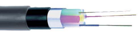
15 Blown Fibre Units (EPFU) 2 Fibre Unit (with ripcord) Diameter Weight Breakout Fibre colours 1.0mm 0.8 g/m 2 minutes (typical) blue, orange Prysmian produces optical fibre units specifically engineered for blown fibre applications. The fibres are contained in a soft inner acrylate layer which cushions the fibres, an outer harder layer which protects the fibre from damage and a low friction layer that assists in improving blowing distance, which is typically in excess of 1000 metres in a single direction. The Sirocco units are available in lengths up to 6000 metres supplied in portable plastic pans for ease of use. The Sirocco units can be supplied in whatever type of fibre is required, including hybrid solutions with a mixture of fibre types. Colour coding indicates the type of fibre (singlemode yellow, 50/125 turquoise/blue and 62.5/125 magenta/red) except for 12 fibre which, with its alternative low friction coating, is coloured grey. Blown Fibre Units 4 Fibre Unit Diameter Weight Breakout Fibre colours 1.0mm 0.8 g/m 3 minutes (typical) blue, orange, green, red 6 Fibre Unit Diameter Weight Breakout Fibre colours 1.1mm 0.95 g/m 4 minutes (typical) blue, orange, green, red, grey, yellow 8 Fibre Unit Diameter Weight Breakout Fibre colours 1.4mm 1.5 g/m 5 minutes (typical) blue, orange, green, red, violet, grey, yellow, brown 12 Fibre Unit Diameter Weight Breakout Fibre colours 1.3mm 1.55 g/m 5 minutes (typical) blue, orange, green, red, violet, grey, yellow, brown, black, white, pink, turquoise Pan Dimensions/Weights 2f 4f 6f 8f 12f Length Pan Kg Pan Kg Pan Kg Pan Kg Pan Kg 500m S 2.9 S 2.9 S 3.1 S 3.3 S m S 3.3 S 3.3 S 3.5 S 4.0 S m S 4.1 S 4.1 S 4.5 S 5.5 D m D 6.9 D 6.9 D 7.1 D 9.7 D m D 8.5 D 8.5 N/A N/A N/A N/A DD 15.8 Pan Code Shallow (S) Deep (D) Double Deep (DD) Dimensions (mm) (l)615 x (w)530 x (h)155 (l)615 x (w)530 x (h)251 (l)615 x (w)530 x (h)392 For detailed product Data Sheets visit 13
16 EPFU Detailed Specification Properties Mechanical International Test Conditions Performance Standard Tensile strength IEC E1 1W N (9.81 x mass of 1km) Pass. Maximum fibre strain = 0.4% Residual fibre strain = 0.05%. Note 1, note 2 Crush IEC E3 100N for 60 seconds Pass. Note 1, note 2 Bend IEC E11 40mm (2 & 4f), 60mm (8f) Pass. Note 1, note 2 Aged bend BT CW1500 pt 4 40mm (2 & 4f), 60mm (8f) at 60ºC for 1000 hrs Pass. Note 1 Environmental Temperature IEC F1-10ºC to + 60ºC for 3 cycles Pass. Note 3, note 4 performance Cold test BS EN ºC for 96 hrs Pass. Note 3, note 4 Condensation test IEC ºC to + 65ºC at 93%RH for 24 hrs x 10 Pass. Note 3, note 4 Water immersion BT CW1500 pt 4 20ºC ± 5ºC for 2000 hrs Pass. Note 3, note 4 Fibre breakout BT CW1500 pt 4 0ºC, 20ºC, 40ºC, length 2m Under 3 minutes (2&4f) from unit Under 5 minutes (8f) Note 1 Note 2 Note 3 Note 4 No significant damage No change in attenuation after test Pass for singlemode = ± 0.07dB/km at 1310nm and 1550nm Pass for multimode = ± 0.25dB/km at 850nm and 1300nm Transmission Performance Maximum Attenuation (db/km) Wavelength Singlemode Low Water Peak MM 62.5/125 MM 50/125 OM3 OM3E (G.652b) (MagniLight G.652d) 850nm (2f-3.2) 2.6 (2f-3.2) 2.6 (2f-3.2) 1300/1310nm (2f-1.2) 0.8 (2f-1.2) 0.8 (2f-1.2) 1383nm nm Bandwidth (MHz.km) Wavelength Singlemode Low Water Peak MM 62.5/125 MM 50/125 OM3 OM3E (G.652b) (MagniLight G.652d) 850nm Minimum Modal nm Effective Modal /1310nm Data Sheets EPFU Range and Technical Parameters Singlemode G.652b Low Waterpeak (MagniLight) G.652d Multimode 62.5/125 Multimode 50/125 Multimode 50/125 OM3 Multimode 50/125 Enhanced OM3 EPFU CasaLight TM bend insensitive G.657.A Fibre Specification EPFU CasaLight Plus TM bend insensitive G.657.B Fibre Specification EPFU Hybrid Product Range Details & Technical Parameters 14 Reference Data Sheet SE001 Reference Data Sheet SE002 Reference Data Sheet SE003 Reference Data Sheet SE004 Reference Data Sheet SE005 Reference Data Sheet SE006 Reference Data Sheet SE007 Reference Data sheet SE008 Reference Data sheet SE009 Reference Data sheet SE010


17 Pre-connectorised EPFU Pre-connectorised EPFU is a surface modified fibre unit for blown fibre applications with factory-terminated connector/s at one end. In certain applications, it may be desirable to minimise field termination of Sirocco. In residential applications, such as when introducing FTTH (Fibre To The Home) networks, it may be recommended to minimise time spent/disruption in customer premises. Prysmian s world-leading Sirocco now incorporates a pre-connectorised solution particularly suitable for FTTH applications. Blown Fibre Units Currently available using a 2 fibre Singlemode EPFU (Enhanced Performance Fibre Unit) stored on a plastic reel with 1 or 2 x SCU connectors on the inner end. The unit will be blown in using a suitable blowing head, with the reel located on a spindle. A number of standard lengths (30, 50, 100, 150, 200, 250, 300, 400 and 500 metres) are available to address a variety of installation requirements. Reference Data Sheet SE008 Please contact your nearest Prysmian Sales Office if you require different EPFU fibre type, counts, or different connector types. Characteristics EPFU fibre type/count Connector type Connector insertion loss Connector return Packaging Singlemode 2 fibre SCU 0.3dB 45dB Boxed Plastic Reel Pre-connectorised EPFU Reel Dispenser The pre-connectorised EPFU reel dispenser is used in conjunction with the Sirocco pre-connectorised EPFU, on reels containing from 30m up to 500m in length. The dispenser allows the EPFU to be easily fed into the Sirocco blowing head for installation to residential and business premises. Reference Data Sheet SA003 For detailed product Data Sheets visit 15
 > Internal Cable (OFNR UL Riser")
18 Blown Fibre Tube Cable Section Content > Direct Install Cable (Duct) > Direct Bury Cable > Direct Bury Non-Metallic Cable > Internal Cable (LSOH) > Internal Cable (OFNR UL Riser Rated)
19 Direct Install Cable (Duct) HDPE low friction tubes of small diameter for blown fibre installations in ducts and sub-ducts. > Recommended for use in ducts and sub-ducts. > Aluminium tape layer acts as a moisture barrier. > Rapid dedicated customer connections using proven mechanical protection of HDPE. > Low friction internal coating for maximum fibre blowing distance. > Each tube accommodates one fibre unit (up to 12 fibres in a unit). > Can be customised to suit user requirements (e.g. tube style, sheath colour, print legend). Blown Fibre Tube Cable Reference Data Sheet ST004 Product Details Assembly of tubes surrounded by an aluminium moisture barrier and an outer polyethylene sheath. Assembly Nominal Minimum Bend Maximum Nominal Drum Lengths Type O.D. (mm) Radius (mm) Tensile (N) Weight (g/m) 1 Way m D* 2000m R 1000m R* 4000m R 2 Way 8.8 x m D 2000m R 1000m R 4000m R 4 Way m D 2000m R 1000m R 4000m R 7 Way m D 2000m R 1000m R 4000m R 12 Way m R 2000m R 19 Way m R 2000m R 24 Way m R 2000m R D* Disposable Drum R* Returnable Drum All figures are nominal, refer to the specific Data Sheet for product detail. Test Performance Tensile Tested in accordance with IEC Method E1. There shall be no permanent deformation of the primary or assembly parts after the applied load (spec. weight kg/km)n at 20mm/minute. Crush Performance Tested in accordance with IEC Method E3. After a maintained load for 1 minute there shall be no deformation of primary tubes greater than 0.5mm. Stress Crack Resistance Tested in accordance with BS6469 Section 99.1 with chemical Caflon CF30. For detailed product Data Sheets visit 17
20 Direct Bury Cable HDPE low friction tubes of small diameter for blown fibre installations in Direct Burial applications. The heavier construction lies flatter in trenches, has increased crush rating and has more resistance to localised bending. > Recommended for direct burial in prepared ground. > Aluminium layer acts as a moisture barrier. > Double sheath to improve crush and bending resistance. > Lower total installed cost compared with installing tube cables in larger bore ducts. > Rapid dedicated customer connections using proven mechanical protection of HDPE. > Low friction internal coating for maximum fibre blowing distance. > Each tube accommodates one fibre unit (up to 12 fibres in a unit). > Can be customised to suit user requirements (e.g. tube style, sheath colour, print legend). Reference Data Sheet ST005 Product Details Assembly of tubes surrounded by an aluminium moisture barrier and two polyethylene sheath layers for improved crush, tensile and bending performance. Assembly Nominal Minimum Bend Maximum Nominal Drum Lengths Type O.D. (mm) Radius (mm) Tensile (N) Weight (g/m) 1 Way m D* 2000m R 1000m R* 4000m R 2 Way 12.2 x m D 2000m R 1000m R 4000m R 4 Way m D 2000m R 1000m R 4000m R 7 Way m D 2000m R 1000m R 4000m R 12 Way m R 2000m R 19 Way m R 2000m R 24 Way m R 2000m R D* Disposable Drum R* Returnable Drum All figures are nominal, refer to the specific Data Sheet for product detail. Test Performance Tensile Tested in accordance with IEC Method E1. There shall be no permanent deformation of the primary or assembly parts after the applied load (spec. weight kg/km)n at 20mm/minute. Crush Performance Tested in accordance with IEC Method E3. After a maintained load for 1 minute there shall be no deformation of primary tubes greater than 0.5mm. Stress Crack Resistance Tested in accordance with BS6469 Section 99.1 with chemical Caflon CF30. 18

21 Direct Bury Non-Metallic Cable HDPE low friction tubes of small diameter for blown fibre installations in last-mile and campus environments. For Direct Burial applications where lightning incidence and other influences establish preference for a totally non-metallic cable. > Totally non-metallic solution. > Recommended for direct burial in prepared ground. > Water swellable tape layer acts as a moisture barrier. > Lower total installed cost compared with installing tube cables in larger bore ducts. > Rapid dedicated customer connections using proven mechanical protection of HDPE. > Low friction internal coating for maximum fibre blowing distance. > Each tube accommodates one fibre unit (up to 12 fibres in a unit). > Can be customised to suit user requirements (e.g. tube style, sheath colour, print legend). Blown Fibre Tube Cable Reference Data Sheet ST009 Product Details Assembly of tubes surrounded by a water swellable tape and two polyethylene sheath layers for improved bending performance. Assembly Nominal Minimum Bend Maximum Nominal Drum Lengths Type O.D. (mm) Radius (mm) Tensile (N) Weight (g/m) 1 Way m D* 2000m R 1000m R* 4000m R 2 Way 12.3 x m D 2000m R 1000m R 4000m R 4 Way m D 2000m R 1000m R 4000m R 7 Way m D 2000m R 1000m R 4000m R 12 Way m R 2000m R 19 Way m R 2000m R 24 Way m R 2000m R D* Disposable Drum R* Returnable Drum All figures are nominal, refer to the specific Data Sheet for product detail. Test Performance Tensile Tested in accordance with IEC Method E1. There shall be no permanent deformation of the primary or assembly parts after the applied load (spec. weight kg/km)n at 20mm/minute. Crush Performance Tested in accordance with IEC Method E3. After a maintained load for 1 minute there shall be no deformation of primary tubes greater than 0.5mm. Stress Crack Resistance Tested in accordance with BS6469 Section 99.1 with chemical Caflon CF30. For detailed product Data Sheets visit 19
22 Internal Cable (LSOH) LSOH low friction tubes of small diameter for blown fibre installations in buildings. > LSOH indoor version with flame retardant properties (IEC Part I & III). > Low smoke emissions BS 7211 (Ap.d). > Contains no halogens. > Low friction internal coating for maximum fibre blowing distance. > Each tube accommodates one blown fibre unit (up to 12 fibres inside). > Tubes are numbered for easy identification. Reference Data Sheet ST003 Product Details Assembly of tubes bound in a LSOH outer sheath. Assembly Nominal Ripcord Minimum Bend Maximum Nominal Drum Lengths Type O.D. (mm) Qty Radius (mm) Tensile (N) Weight (g/m) 1 Way m D* 2000m R 1000m R* 4000m R 2 Way 7.2 x m D 2000m R 1000m R 4000m R 4 Way 12.2 x m D 2000m R 1000m R 4000m R 7 Way m D 2000m R 1000m R 4000m R 12 Way m D 2000m R 1000m R 4000m R 19 Way m D 2000m R 1000m R 24 Way m R 2000m R D* Disposable Drum R* Returnable Drum All figures are nominal, refer to the specific Data Sheet for product detail. Test Performance Material Compliance > Flammability IEC Part 1 and Part 3 > Low Acid Gas Emission IEC > No Halogen Content > Temperature Index 270ºC > Smoke to BS 7211 (Ap.d) Tensile Tested in accordance with IEC Method E1. There shall be no permanent deformation of the primary or assembly parts after the applied load (spec. weight kg/km)n at 20mm/minute. Crush Performance Tested in accordance with IEC Method E3. After a maintained load for 1 minute there shall be no deformation of primary tubes greater than 0.5mm. Stress Crack Resistance Tested in accordance with BS6469 Section 99.1 with chemical Caflon CF30. 20
 and NEC 770-53(b).")
23 Internal Cable (OFNR UL Riser Rated ) Low friction tubes of small diameter for blown fibre installation in building risers as specified by NEC article (b) and (b). This cable is UL listed type OFNR. > Suitable for Riser applications where flame propagation characteristics are required in accordance with NEC article (b) and NEC (b). > UL listed type OFNR. > Low friction internal coating for maximum fibre blowing distances. > Tube cable configurations available: 1, 2, 4, 7, 12, 19 & 24 way. > Each primary tube, 5 mm OD x 3.5 mm ID, accommodates one fibre unit (up to 12 fibres inside). > Solid white/cream coloured tubes. > Print details include batch number, meter count and individual tube number. Blown Fibre Tube Cable Reference Data Sheet ST011 Product Details Assembly of tubes bound in a sheath of flame retardant material suitable for Riser applications. Assembly Nominal Ripcord Minimum Bend Maximum Nominal Reel Lengths Type O.D. (mm) Qty Radius (mm) Tensile (N) Weight (g/m) 1 Way m D* 2000m D 1000m D 4000m D 2 Way 7.0 x m D 2000m D 1000m D 4000m D 4 Way 12.0 x m D 2000m D 1000m D 4000m D 7 Way 15.7 x m D 2000m D 1000m D 4000m D 12 Way 20.0 x m D 2000m D 1000m D 4000m D 19 Way 24.0 x m D 2000m D 1000m D 24 Way 31.0 x m D 2000m D 1000m D D* Disposable Drum All figures are nominal, refer to the specific Data Sheet for product detail. Test Performance Material Compliance > UL listed 1666 (OFNR) > NEC (b) > NEC (b) Tensile Tested in accordance with IEC Method E1. There shall be no permanent deformation of the primary or assembly parts after the applied load (spec. weight kg/km)n at 20mm/minute. Crush Performance Tested in accordance with IEC Method E3. After a maintained load for 1 minute there shall be no deformation of primary tubes greater than 0.5mm. Stress Crack Resistance Tested in accordance with BS6469 Section 99.1 with chemical Caflon CF30. For detailed product Data Sheets visit 21
24 Notes 22

25 Connectivity Section Content Connectivity Fibre Connectivity > RS3000 Rack > SRS3000 1U Splice & Patch Shelf > SRS3000 1U Patch Only Shelf > SRS3000 1U Splice Only Shelf > SRS3000 Patchcord Storage Shelf > SRS3000 Distribution Sub-Rack > PSP Splice & Patch Shelf > SC3000 Street Cabinet > Compact Node Joint > Blown Fibre Generic Joint > MJS Modular Joint > Int/Ext Compact Termination Box > External Customer Splice Box > Internal Customer Splice Box > Riser Box > Multi Dwelling Unit (MDU) Cabinets > Large Termination Box (72f) > Ultra Compact Termination Box > Compact Termination Box Tube Connectivity > Blown Tube Patch Shelf > Tube Patching Panel > Tube Distribution Closure MKII > Customer Lead-in Units > Blown Fibre Gas Seal Unit > FTTH Streetside Cabinet > Branching Units > Internal TDU
. The rack is supplied with side panels and transparent doors.")
26 RS3000 Rack The RS3000 Rack is a standard rack with 19 mounting rails, used to accommodate a range of SRS3000 shelves and subracks or any other 19 rack mounted products. The rack is 900mm wide by 300mm in depth and is available in 42U and 47U heights (2000 and 2200mm). The rack is supplied with side panels and transparent doors. Cable brackets are supplied in the left hand side of the rack to enable a range of cable anchor brackets to be installed. Mandrels are supplied in the right hand side of the rack to manage and store patchcords. The maximum capacity of the rack is 2160 fibres (based on the 47U rack on a splice + patch basis). Additional Items Optional > SRS3000 Splice and Patch Shelf > SRS3000 Patch Only Shelf > SRS3000 Splice Only Shelf > SRS3000 Patchcord Storage Shelf > SRS3000 Sub-Racks (2U and 3U) > ARS Cable Anchor Bracket > BEM Cable Anchor Bracket Reference Data Sheet RA007 > The rack can accommodate the range of SRS3000 shelves and subracks. Please note that other 19 rack mounted products and equipment can be mounted into the RS3000 rack. Refer to the other products within the OAsys range. > SRS3000 shelves and sub-racks are available for Splicing Only, Patching Only, Splicing + Patching and Patchcord Storage. They can be supplied in 1U, 2U or 3U formats. > Up to 40 single (1U) SRS3000 shelves can be accommodated in a 42U rack providing a capacity of 1920 fibres on a splice and patch basis. Up to 45 single (1U) SRS3000 shelves can be accommodated in the 47U rack, providing a capacity of 2160 fibres on a splice and patch basis. > The rack is supplied fully configured as a composed rack with side channels, doors, 19 mounting rails, patchcord storage mandrels and cable anchor brackets. > Cables are anchored and distributed in the left hand side of the rack using ARS and BEM cable anchors. See additional items for further information. > Patchcord storage drums are supplied in the right hand side of the rack, for patchcord storage and bend management. > Locks are available for restricted access to the rack. Characteristics Maximum capacity 42U 40 SRS 3000 shelves (1U) 47U 45 SRS 3000 shelves (1U) Maximum Fibre Capacity (using SRS3000 products) 42U 1920 (splice only, patch only and splicing + patching with SC and LC connectors) 42U 960 (patch only and splicing + patching with FC, ST and E2000 connectors) 47U 2160 (splice only, patch only and splicing + patching with SC and LC connectors) 47U 1080 (patch only and splicing + patching with FC, ST and E2000 connectors) Required space envelope (mm) 42U (h)2000 x (w)900 x (d)300 Material 47U Mild Steel (h)2200 x (w)900 X (d)300 Finish Painted light grey (RAL 7035) Packing Dimensions (mm) 42U (h)2280 x (w)965 x (d)350 47U (h)2280 x (w)965 x (d)350 Packed Weight (Kg) 42U U Net Weight (Kg) 42U U

27 SRS3000 1U Splice & Patch Shelf The SRS3000 Splice and Patch Shelf is a modular unit available in a variety of configurations for integration in to 19 and ETSI racks, street side or wall mounted cabinets. The product consists of a metal chassis, a plastic light weight splice and patch module and a cable anchoring system. The product has a capacity of up to 48 fibres in a 1U unit for SC and LC type connectors, and up to 24 fibres for FC, ST and E2000 type connectors. The panel has in built fibre management to ensure the product is installed correctly and the same every time by installers. Connectivity The shelf is fully compatible with all optical cable types, with blown fibre tube cables and can be configured to hold optical devices (i.e. splitters & WDM s) on request. > Modular panel design enables easy capacity upgrades from 12 to 48 fibres. > Very high splice and patch density of 48 fibres for SC and LC connector types in 1U. Additional Items Required > Splice Protectors Optional > Crimp Splice Protector Holders > ETSI Conversion Brackets > Rear Mounting Brackets > Rack Fixing Kit > ARS Cable Anchor (additional) > Upgrade Kits > Blown Fibre Manifold > Patch-cords (see datasheet AC004) > High splice and patch density of 24 fibres for ST, FC and E2000 connector types in 1U. > Suitable for installation into 19 / ETSI / ANSI racks, wall mounted cabinets and street-side cabinets. > Splice and patch module pivots outwards for easy fibre access and maintenance. > The drop down front panel prevents accidental disconnection of patchcords and provides additional space for patchcord routing during installations. > All fibres are positively bend managed to a 30mm radius. > Supplied with a large cover label and front panel labels for easy identification and data recording. > Splice and patch bay is covered with a detachable lid (secured with two screws) to protect the splices and pigtails once installed. > The panel can be used for optical splitters and other passive devices in alternative configurations. Please contact Prysmian for further information. > Can accommodate most cable types including blown fibre tube cables. Note: for 48f 1U shelves a 2mm Patch-cord size should be used. Reference Data Sheet RM014 Characteristics Maximum capacity Number of terminations Number of output patchcords: Maximum cable diameter Required space envelope (mm) Operating temperature 48 for SC or LC connectors 24 for FC, ST and E2000 connectors 48 with 2mm diameter patch cords 14mm Material Metalwork Mild Steel Plastics: (w)447 x (d)245 x (h) C to +60 C (5 to 93% RH) High Impact Polystyrene Finish Metalwork Painted light grey RAL 7035 Packing dimensions (mm) Plastics: Light Grey RAL 7035 (w)560 x (d)290 x (h)175 Weight (kg) Packed weight: 2.95 Net weight: 2.40 For detailed product Data Sheets visit 25

28 SRS3000 1U Patch Only Shelf The SRS3000 Patch Only Shelf is a modular unit available in a variety of configurations for integration in to 19 and ETSI racks, street side or wall mounted cabinets. The product consists of a metal chassis, a plastic light weight patch module and a cable anchoring system. The units can be installed in to standard 19 racks, or ETSI and ANSI/TEP1E racks using conversion brackets. The product has a capacity of up to 48 adapters in a 1U unit for SC and LC type connectors, and up to 24 adapters for FC, ST and E2000 type connectors. The shelf is fully compatible with all optical cable types and can also be used with blown fibre tube cables. > Modular panel design enables easy capacity upgrades from 12 to 48 adapters. Additional Items Optional > ETSI Conversion Brackets > Rear Mounting Brackets > ARS Cable Anchor (additional) > Upgrade Kits > Patch-cords (see datasheet AC004) Reference Data Sheet RM019 > Very high patch density of 48 adapters for SC and LC connector types in 1U and High patch density of 24 adapters for ST, FC and E2000 connector types in 1U. > Suitable for installation into 19 / ETSI / ANSI racks, wall mounted cabinets and streetside cabinets. > Patch module pivots outwards for easy fibre access and maintenance. > The panel can be used for optical splitters and other passive devices in alternative configurations. Please contact Prysmian for further information. > The drop down front panel prevents accidental disconnection of patchcords and provides additional space for patchcord routing during installations. > All fibres are positively bend managed to a 30mm radius. > Supplied with a large cover label and front panel labels for easy identification and data recording. > Patch bay is covered with a detachable lid (secured with two screws) to protect the fibres once installed. > Can accommodate most cable types including blown fibre tube cables. Note: for 48f 1U shelves a 2mm Patch-cord size should be used. Characteristics Maximum capacity Max number of terminations Max number of output patchcords Max Cable Diameter Required space envelope (mm) Operating temperature Material Metalwork Plastics 48 for SC or LC connectors 24 for FC, ST and E2000 connectors 48 with 2mm diameter patch cords 14mm (w)447 x (d)245 x (h) o C to + 60 o C (5 to 93% RH) Mild Steel High Impact Polystyrene Finish Metalwork Painted light grey RAL 7035 Plastics Light Grey RAL 7035 Packing Dimensions (mm) Packed Weight (kg) 2.95 Net weight (kg) 2.40 (w)560 x (d)290 x (h)175 26

29 SRS3000 1U Splice Only Shelf The SRS3000 Splice Only Shelf is a 1U shelf for the splicing of up to 48 fibres. The shelf can be installed into 19 and ETSI racks, street side or wall mounted cabinets. The product consists of a metal chassis, a plastic light weight splicing module and a cable anchoring system. The product can be used for a variety of configurations such as cable to cable splicing, cable to blown fibre splicing or cable to ruggedised pigtail splicing. For cable to cable or blown fibre splicing, the shelf is supplied with a bulkhead connector panel fitted with six 5mm bulkhead connectors. For cable to ruggedised pigtail splicing the shelf is supplied with panels that enable Aramid restraints to be fitted and secured. Connectivity Additional Items Required > Splice Protectors Optional > Crimp Splice Protector Holders > ETSI Conversion Brackets > Rear Mounting Bracket > ARS Cable Anchor (additional) > Aramid Restraint Kits Reference Data Sheet RM018 > Suitable for installation into 19 / ETSI / ANSI racks, wall mounted cabinets and street-side cabinets. > The shelf has a capacity of up to 48 fibre splices. > The shelf is supplied with splice protector holders for 2.2mm heat shrink splice protectors. Crimp splice protectors can also be accommodated by using crimp splice protector holders. Refer to additional items. > Can accommodate most cable types including blown fibre tube cables. > Splice module pivots outwards for easy fibre access and maintenance. > The shelf can be used for optical splitters and other passive devices in alternative configurations. Please contact Prysmian for further information. > The drop down front panel prevents accidental disconnection of fibre routing tubes during installations. > All fibres are positively bend managed to a 30mm radius. > Supplied with a large cover label and front panel labels for easy identification and data recording. > Splice bay is covered with a detachable lid (secured with two screws) to protect the fibres once installed. Characteristics Maximum capacity Number of splices 48 Splice protectors accommodated Number of output patchcords Max Cable Diameter Required space envelope (mm) Operating temperature Material Metalwork Plastics 2.2mm heat shrink or crimp 48 with 2mm diameter patch cords 14mm (w)447 x (d)245 x (h) o C to + 60 o C (5 to 93% RH) Mild Steel High Impact Polystyrene Finish Metalwork Painted light grey RAL 7035 Plastics Light Grey RAL 7035 Packing Dimensions (mm) Packed Weight (kg) 2.95 Net weight (kg) 2.40 (w)560 x (d)290 x (h)175 For detailed product Data Sheets visit 27

30 SRS3000 1U Patchcord Storage Shelf The SRS3000 Patchcord Storage Shelf is a 1U shelf used for the storage of patchcords or the storage of patchcord overlength. The shelf can be installed in to 19 / ETSI / ANSI racks, street side or wall mounted cabinets. The product consists of a metal chassis and a plastic light weight module. The product has a capacity of up to 48 patchcords in a 1U unit. Additional Items Optional > ETSI Conversion Brackets > Rear Mounting Bracket > Patchcords (see data sheet AC004) Reference Data Sheet RM020 > Suitable for installation into 19, ETSI and ANSI racks. > Can be used to store patchcords prior to installation or to store patchcord overlength. > Storage capacity of up to 2 metres of 24 patchcords 2.8mm in diameter or 48 patchcords of 2.0mm in diameter. > Overlength capacity of up to 2.5 metres of 24 patchcords 2.8mm in diameter or 48 patchcords of 2.0mm in diameter. > Can be upgraded to an SRS3000 Patch Only Shelf. Refer to the Upgrade Kits in the additional items section of Prysmian data sheet RM019 SRS3000 Patch Only Shelf. > Storage module pivots outwards for easy patchcord access. > All fibres are positively bend managed to a 30mm radius. > Supplied with a large cover label and front panel labels for easy identification and data recording. > Patchcords are available for supply from Prysmian. Refer to Prysmian data sheet AC004. Characteristics Maximum capacity Storage 2.0mm Patchcords 48 x 2.0 metres 2.8mm Patchcords 24 x 2.0 metres Overlength 2.0mm Patchcords 48 x 2.5 metres 2.8mm Patchcords Required space envelope (mm) 24 x 2.5 metres Material Metalwork Mild Steel Plastics (w)447 x (d)245 x (h)44.5 High Impact Polystyrene Finish Metalwork Painted light grey RAL 7035 Operating temperature Packing dimensions (mm) Plastics Light Grey RAL ºC to +60ºC (5 to 93% RH) (h)560 x (d)290 x (h)175 Weight (kg) Packed weight: 2.85 Net weight:

31 SRS3000 Distribution Sub-Rack The SRS3000 Distribution Sub-Rack is a modular sub-rack available in a variety of configurations for integration into 19 / ETSI / ANSI racks, street-side cabinets or wall mounted cabinets. The product consists of a metal chassis available in 1U, 2U and 3U into a which a choice of modules are loaded. The module types available are Splice and Patch, Patch Only, Splice Only and Patchcord Storage. This allows users to customise the product for different applications whilst using the same building blocks in each sub-rack. The splice and patch, splice only and patch only modules can be supplied in 12, 24 or 48 fibre capacities in a 1U unit. They are supplied with a range of connector types for both singlemode and multimode fibre, which can be factory fitted or supplied as a kit. The cable anchoring systems allows all types of optical cables (including blown fibre) to be routed onto the sub-rack and modules. Connectivity > Modular system for installation into 19 / ETSI / ANSI racks, street-side cabinets and wall mounted cabinets. Additional Items Required > Splice Protectors Optional > ETSI Conversion Brackets > Rear Mounting Bracket > ARS Cable Anchor (additional) > BEM Cable Anchor > Upgrade Kits > Blown Fibre Manifold > Aramid Restraint Kits > Patchcords (see datasheet AC004) > The sub-rack can be supplied fully configured or modules can be supplied empty for upgrading at a later date. > Chassis are available in 1U, 2U and 3U options are supplied front mounted as standard. Rear mounting brackets are available as an option. > Fibres are actively managed to minimum bend diameters throughout the Splicing and Patching, Patching only, Splicing only and Patchcord Storage Modules. > Splicing and bare fibre excess storage is performed inside a tray protected by a cover to prevent any accidental damage when open & closing the shelves. > Modules pivot outwards for easy access. > Cables are completely protected from entry to exit of the panel. > Optical devices (i.e. Splitters & WDM s) can be mounted within the modules. Please contact Prysmian to discuss your requirements). > Wall mount 19 and ETSI cabinets are also available. Please contact Prysmian for further details. > Modules have drop down fronts for easier patchcord routing, enclosing patch-cords, and protecting adapters. > 2 large labelling areas are provided for identification recording per module. Reference Data Sheet RM015 Characteristics Maximum Capacity For detailed product Data Sheets visit Chassis Size 1U 2U 3U Number of splices 48 ( SC & LC), 96 (SC & LC), 144 (SC & LC), 24 ( FC, ST & E2000) 48 (FC, ST & E2000) 72 (FC, ST & E2000) Number of output patchcords 48 with 2mm diameter 96 with 2mm diameter 144 with 2mm diameter patchcords patchcords patchcords Maximum cable diameter 14mm Required Space Envelope (mm) (w)447 x (d)245 x (h)44.5 (w)447 x (d)245 x (h)89.0 (w)447 x (d)245 x (h)133.5 Operating Temperature Material Metalwork Mild Steel Plastics -20 C to +60 C (5 to 93% RH) High Impact Polystyrene Finish Metalwork Painted light grey RAL 7035 Plastics Light Grey RAL 7035 Packing Dimensions (mm) (w)525 x (d)330 x (h)80 (w)525 x (d)330 x (h)240 (w)525 x (d)330 x (h)240 Weight (kg) Packed Weight Net Weight

32 PSP Splice and Patch Shelf The PSP splice and patch shelf is a low cost plastic 1U shelf designed for data market applications. The shelf allows the connection of up to 48 fibres on each unit and is compatible with 19 and ETSI racks. Cables enter at the rear of the shelf on the left hand side and pigtails exit the unit from the front face. The light weight product is easy to install and in built fibre management on the panel ensures that all installations are the same every time it is used which eliminates installation errors. The shelf is supplied either empty, in kit format, or with the pigtails and adapters pre-installed. Additional Items Required > Splice Protectors Optional > ARS Cable Bracket > Adapters (see data sheet AC002) > Pigtails (see data sheet AC003) > Patchcords (see data sheet AC004) > Crimp splice bay > 19 ETSI Brackets > Upgrade Kit > Cage Nut Kit > Blown Fibre Manifold > High density low cost compact design for up to 48 fibres. > Compatible with SC, FC, E2000, LC, ST connecter types. > Cables anchor on the rear of the unit using a cable anchor plate supplied. > Unit manufactured from high strength fire retardant plastic to give a light weight solution. > Supplied either as an empty unit, in kit format (with pigtails and adapters in a bag) for installer loading, or with the pigtails and adapters pre-installed by Prysmian. > All fibres are positively managed to a 30mm minimum bend radius. > Shelf pivots out to for access to the splice tray and pigtail area. > Shelf can be used as a patch only solution and allows excess cable lengths to be stored. > Stackable splice bay allows for easy upgrade of splicing capacity. > The shelf offers the ability to terminate up to 2 cables and allows through splicing of fibres. > Compatible with Sirocco blown fibre cables using a Blown Fibre Manifold. The manifold enables up to 6 blown fibre tubes to be routed to a single shelf. > Available in 2 colours grey RAL 7035 and black. Reference Data Sheet RM012 Characteristics Number of splice trays 1 Maximum fibre capacity 24 (SC, ST, FC, E2000) 48 (LC) 48 (SC) - Coming soon. Maximum cable diameter 18mm Required space envelope (mm) (w)481 x (d)230 x (h)44 Operating temperature -20 C to +50 C (5 to 95% RH) Material High Impact Polystyrene Finish Light Grey (RAL 7035) Packing dimensions (mm) (w)530 x (d)330 x (h)80 Weight (kg) Packed weight: 1.3 Net weight:


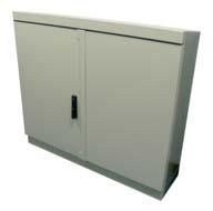
33 SC3000 Street Cabinet The SC3000 Street Cabinet is a standard cabinet with 19 mounting rails, used to accommodate a range of SRS3000 shelves and sub-racks or any other 19 rack mounted products. The cabinet is 1200mm wide by 330mm in depth and 1100mm in height. The cabinet is supplied with two hinged doors doors. Cable brackets are supplied in the left hand side of the cabinet to enable a range of cable anchor brackets to be installed. Mandrels are supplied in the right hand side of the cabinet to manage and store patchcords. The cabinet can accommodate up to 16 1U shelves and can accommodate standard optical cables and blown fibre tube cables. Connectivity > The cabinet can accommodate the range of SRS3000 shelves and sub-racks or any other 19 rack mounted products. > SRS3000 shelves and sub-racks are available for Splicing Only, Patching Only, Splicing + Patching and Patchcord Storage. They can be supplied in 1U, 2U or 3U formats. > Up to 16 single (1U) SRS3000 shelves can be accommodated in the cabinet providing a capacity of 768 fibres on a splice and patch basis. > The cabinet is supplied fully configured with patchcord storage mandrels and cable anchor brackets. Additional Items Optional > SRS3000 Splice and Patch Shelf > SRS3000 Patch Only Shelf > SRS3000 Splice Only Shelf > SRS3000 Patchcord Storage Shelf > SRS3000 Sub-Racks (2U and 3U) > ARS Cable Anchor Bracket > BEM Cable Anchor Bracket > Cable Entry Glands > Fitted with cable gland plates in the left and right hand side of the cabinet. Cable entry glands available as required. See additional items. > Cables are anchored and distributed in the left hand side of the cabinet using ARS and BEM cable anchors. See additional items for further information. > Patchcord storage drums are supplied in the right hand side of the rack, for patchcord storage and bend management. > The cabinet has a built in seal providing protection to IP54. > Standard colour is RAL Other colours available on request. > Fitted with a 300mm plinth with a front access panel to ease cable installation and routing. Characteristics Reference Data Sheet OP023 Maximum Capacity 16U (16 x SRS 3000 shelves 1U) Fibre capacity 768 (splice only, patch only and splicing + patching with SC and LC connectors) 384 (patch only and splicing + patching with FC, ST and E2000 connectors) Required space envelope (mm) (h)1300 x (w)1200 x (d)330 Material Finish Sealing Packing Dimensions (mm) Mild Steel Painted RAL 7044 (other colours available) IP54 (h)1450 x (w)1350 x (d)600 Weight (kg) Packed weight: 90.0 Net weight: 85.0 For detailed product Data Sheets visit 31
 and is pre-fitted with a pressure relief valve, to prevent")
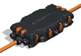
34 Compact Node Joint The Compact Node Joint is used for ready access applications within the external optical fibre network. It can be used where Sirocco cables are required to be installed and spliced within the closure (either to cables or blown fibre cables) and is pre-fitted with a pressure relief valve, to prevent accidental pressurisation during blown fibre installation. The joint is supplied with 12 single circuit splice trays, each able to accommodate up to 12 fibres and sufficient components for the installation of one input cable. Blown fibre distribution cables can be installed using blown fibre cable entry kits. Additional Items Required > Splice Protectors Optional > Cable Entry Kit > Blown Fibre Cable Entry Kit > Blown Fibre Distribution Kit > Water Blocking Kit > Support Tool > Mounting Brackets Reference Data Sheet OP005 > Each joint is supplied with 12 splice trays, each able to accommodate up to 12 fibres. > All fibres are positively managed to maintain a 30mm minimum bend radius within the joint. > Fully compatible with Sirocco product range. The closure base is pre-fitted with a pressure relief valve which prevents accidental pressurisation of a sealed closure during blown fibre installation. > The closure base has 6 circular entry ports. Cables up to 22mm in diameter can be installed into each port. > All cables are sealed using adhesive lined heatshrink sleeves. The base entry ports are pre-shot blasted and configured with easy knock out ends, eliminating the need for cutting and abrading. > The joint is quickly and easily re-enterable without the need of further consumables. The sealing clamp can be locked if required. > On installation all cable elements are organised, oversleeved with protective tubing and identified with number collets. > Splice trays hinge upwards individually, providing full access to spliced fibres without disturbance to adjacent live fibre circuits. > Blown fibre cables can be installed into the joint using Blown Fibre Cable Entry Kits, and fibre units can be manifolded to different tubes/trays using the Blown Fibre Distribution Kit. Characteristics Maximum Capacity No. of cable ports 6 circular Maximum cable diameter 22mm No. of splice trays 12 Maximum fibre capacity 144 Required Space Envelope (mm) (h)390 x (w)231 x (d)164 IP Rating 68 Operating Temperature Packing Dimensions (mm) -20 C to +60 C (5 to 95% RH) (h)480 x (w)250 x (d)210 Weight (kg) Packed weight: 2.8 Net weight:

35 Blown Fibre Generic Joint The Blown Fibre Generic Joint is used in applications where blown fibre cables are required to be installed and spliced within the closure to other optical fibre cables or other blown fibre units. The closure is fitted with a pressure relief valve to prevent accidental pressurisation of a sealed closure during blown fibre installation. Connectivity The joint is supplied without splice trays and accessories and is therefore configured using Joint Upgrade Kits, General Accessories and Blown Fibre Accessories. Additional Items Required > Splicing and/or Splitting Modules > Joint Upgrade Kits > Splice Protectors Optional > Fibre Circuit Management Kits > Mounting Brackets > Blown Fibre Accessories > Accessories Reference Data Sheet OP003 > The joint has a capacity of 30 splice trays which is upgradeable to 54 trays, using a Long Cap Conversion Kit. > All fibres are positively managed to maintain a 30mm minimum bend radius within the joint. > The closure base has 6 circular entry ports and one oval entry port for mid span breakout applications. > Cables up to 30mm in diameter can be installed into each port. > All cables are sealed using adhesive lined heatshrink sleeves. The base entry ports are pre-shot blasted and configured with easy knock out ends, eliminating the need for cutting and abrading. > The joint is quickly and easily re-enterable without the need of further consumables. The sealing clamp can be locked if required. > The closure base is pre-fitted with a pressure relief valve which prevents accidental pressurisation of a sealed joint during blown fibre installation. > Each closure is supplied empty, which can be configured to meet the network requirement using External Plant Upgrade Kits, Accessories and Blown Fibre Accessories. > A number of mounting bracket options are available for securing the joint. > Large range of accessories available please contact Prysmian for a detailed datasheet. Characteristics Maximum Capacity No. of cable ports Maximum cable diameter No. of splice trays 6 circular,1 oval 30mm 30 (Short cap) 54 (Long cap) Maximum fibre capacity 8/tray 240 (Short cap) 432 (Long cap) 12/tray 360 (Short cap) 648 (Long cap) Dimensions (mm) Short cap (h)490 x (Ø)270 Long cap (h)620 x (Ø)270 Weight (kg) Packed weight: 5.1 Net weight: 4.0 IP Rating 68 Operating Temperature -20 C to +60 C (5 to 95% RH) For detailed product Data Sheets visit 33

36 Modular Jointing System MJS-CP The Modular Jointing System (MJS-CP) is used for access applications within the external optical network and can be used for track, spur and loop applications. It can accommodate a wide variety of cables such as loose tube, central loose tube, ribbon and blown fibre. The modular tray system is designed for positive fibre management for Single Circuit Management (SCM) and Single Element Management (SEM), and the splice trays can accommodate a variety of different types of splice protectors and splitters. Cable entries to the joint can sealed using either heat-shrinks or a range of mechanical seals. Additional Items Required > Cable Entry Kits > Splicing Module (SCM, SEM or Ribbon) > Splice Protectors > Mounting Bracket Optional > Splitter Modules > Patching Module Reference Data Sheet OP010 Characteristics > For each type of splice tray, splice holders are available for crimp, heat shrinkable or mechanical (for SEM only) splice protectors. > All fibres are positively managed to maintain a 30mm minimum bend radius. > Splice trays hinge upwards individually, allowing full access to spliced fibres without disturbance to live fibres in adjacent trays. > Splitter modules can be mounted within the joint and can be supplied preassembled. Any combination of splitters between 1x2 to 1x32 can be accommodated. > Four different cap lengths are available to configure the closure according to the number of trays required. > The closure base has 6 circular entry ports and one oval port. > Cables up to 30 mm in diameter can be installed into each port using adhesive heat-shrink sleeves. > Mechanical seals are available for the circular port enabling up to four cables. > On each circular port, additional multi cable adapter entry kits are available to seal independently 3 cables (max OD: 12 mm). > The joint is quickly and easily re-enterable without the need of further consumables. The sealing clamp can be locked if required. > A toning connector is supplied fitted into the base for use as toning point. > The closure cap contains a pressure test valve to test the seal of the closure after installation. Maximum Capacity Number of cable ports 1 oval + 6 circular (18 using the multi Cable Adapter Entry Kit) Maximum cable diameter (mm) 30 (12mm if the Splitter Entry Port is used on the Circular Port) MJS-CP/0.00 MJS-CP/1.00 MJS-CP/2.00 MJS-CP/3.00 Short Cap Medium Cap Long Cap Extra Long Cap Required space envelope (mm) (l)440 x (d)250 (l)500 x (d)250 (l)610 x (d)250 (l)685 x (d)250 Maximum capacity for Single Element Management (SEM) Maximum number of trays 20 trays ( ) 30 trays ( ) 50 trays ( ) 60 trays ( ) Maximum splices 240f 360f 600f 720f Maximum capacity for Single Circuit Management (SCM) Maximum number of trays 32 trays ( ) 48 trays ( ) 80 trays ( ) 96 trays ( ) Maximum splices 128f 184f 320f 384f Maximum capacity for Ribbon Fibre Management (RFM) Maximum number of trays 20 trays ( ) 30 trays ( ) 50 trays ( ) 60 trays ( ) Maximum splices 160f 240f 400f 480f Operating temperature -20 o C to + 60 o C (5 to 95% RH) Material Cap & Base: Polypropylene mixture Splice trays: PC-ABS Packing Dimensions (mm) (l)550 x (w)330 x (d)330 (l)750 x (w)330 x (d)330 (l)750 x (w)330 x (d)330 (l)750 x (w)330 x (d)330 Packed Weight fully equipped (kg)

37 Internal/External Compact Termination Wall Box The Internal/External Compact Termination Wall Box is designed for use in residential, small and large business premises. The unit houses a single splice tray and allows fibres from external cables to be spliced to pigtails for connection to customer drop patchcords. Connectivity The external cable enters from the bottom of the unit, with the customer drop cables (patchcords) exiting from the bottom of the unit or directly through the back of the box and through the wall. Additional Items Required > Splice Protectors Optional > Gas Seal Connector Reference Data Sheet WM017 > The Termination Box can be mounted internally or externally. > Removable cover for easy access and fitted with a lock for enhanced security. > Unit manufactured from fire resistant UL94-V0 rated material. > Single hinged splice tray provides access for working. The splice tray is supplied with interchangeable inserts and can accommodate up to 8 fusion splice protectors (heatshrink or crimp) or mechanical splices. > Customer drop cables exit from the bottom of the unit and are sealed using a split grommet. Drop cables can be routed through the wall. > Up to 4 SC or 8 LC pigtails and adapters can be accommodated. > All fibres positively managed to 30mm minimum bend radius. > External input cable (up to 11mm diameter) enters the unit from the bottom. > For Sirocco blown fibre applications, a Gas Seal Connector can be housed within the box. Characteristics Maximum Capacity No. of splice trays 1 Maximum fibre capacity 8 (LC) or 4 (SC) Maximum cable diameter 11mm Required space envelope (mm) (h)185 x (w)140 x (d)32 IP Rating 55 Operating Temperature Packing Dimensions (mm) -20ºC to +50ºC (5 to 95% RH) (h)195 x (w)150 x (d)40 Weight (kg) Packed weight: 0.35 Net weight: 0.30 For detailed product Data Sheets visit 35
 to be spliced to pigtails and fed through the wall fabric using a 25mm")
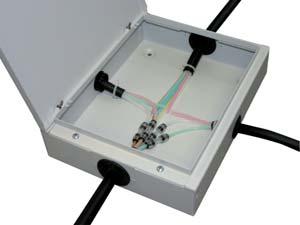
38 External Customer Splice Box The External Customer Splice Box is designed for use on the external wall of residential or small business premises. The unit, which houses a single splice tray, is used to enable fibres from external cables (blown fibre or conventional) to be spliced to pigtails and fed through the wall fabric using a 25mm diameter conduit and then connected to the optical network unit. It can also be used as a transition point between external and internal cable, protecting the cable through the wall fabric. The unit can be supplied without pigtails or adapters, or with 1 to 4 SC/UPC or SC/APC pigtails and adapters as standard (other types available on request). Additional Items Optional > Splice Protectors > Security Screw Kit > Resin Pack > Disposable Funnel Kit Reference Data Sheet WM014 > Compact wall mounted unit typically used for residential or small business premises. > Removable cover fitted with re-enterable seal. Water ingress protection to IP66. > Tamperproof cover security screws available as an option. > Unit manufactured from UV resistant material. > Standard kit supplied complete with all components necessary to splice an external cable to 4 pigtails to be taken through the wall. For applications where 12f are to be spliced (external to internal cable) extra splice protectors will be required. > Single hinged splice tray enables access for working. Tray cover provides circuit protection and contains fibre ID label. > Rear cable entry port allows pigtails to enter the customer premises, protected by 25mm diameter conduit. An Internal Customer Lead-In Unit (CLI) is used to manage the bend radius of the pigtails or cable at the inside wall. > All fibres positively managed to 30mm minimum bend radius. > Cables up to 13mm in diameter can be accommodated with a cable gland. Diameters up to 18mm can be accommodated using a cable port adapter. > Cable interstices can be sealed against water/gas ingress at the entry port if required using a quick set resin (optional items Resin Pack and Disposable Funnel Kit). > Compatible with blown fibre products. Characteristics Maximum capacity No. of splice trays 1 Maximum fibre capacity 12 Maximum cable diameter IP rating 66 Required space envelope (mm) Packing dimensions (mm) 18mm (h)150 x (w)220 x (d)50 (h)160 x (w)230 x (d)60 Weight (kg) Packed weight: 0.55 Net weight:

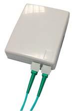
39 Internal Customer Splice Box The Internal Customer Splice Box is designed for use in residential, small and large business premises. The unit houses a single splice tray and allows fibres from internal or external cables to be spliced to pigtails for connection to the optical network unit. The unit can be quickly installed within a home, office or communication room environment. Connectivity The unit can be supplied with 4, 8 or 12 pigtails and adapters, either SC/UPC or SC/APC (other types available on request). Additional Items Optional > Gas Seal Connector > Security Screw Kit > Customer Lead-in Unit > Resin Pack > Disposable Funnel Kit Reference Data Sheet WM015 > Compact wall mounted unit used for residential, small and large business premises. > Removable cover for easy access. > Tamperproof cover security screws available as an option. > Unit manufactured from fire resistant UL94-V0 rated material. > Single hinged splice tray enables access for working. Tray cover provides circuit protection and contains fibre ID label. > Pigtails exit from the bottom of the unit. > Up to 12 SC type pigtails can be accommodated. Other adapter types can be accommodated. Contact Prysmian for further information. > All fibres positively managed to 30mm minimum bend radius. > Cables up to 13mm in diameter can be accommodated with a cable gland. Diameters up to 18mm can be accommodated using a cable port adapter. > If an external cable is terminated, cable interstices can be sealed against the ingress of water/gas at the entry port using a quick set resin (optional items Resin Pack and Disposable Funnel Kit). > Compatible with blown fibre products. Note: for certain applications where external blown fibre tubing is terminated, a Gas Seal Connector (not supplied) will be required to seal the tube. Characteristics Maximum capacity No. of splice trays 1 Maximum fibre capacity 12 Maximum cable diameter 18mm IP rating 45 Required space envelope (mm) Packing dimensions (mm) (h)150 x (w)220 x (d)50 (h)160 x (w)230 x (d)60 Weight (kg) Packed weight: 0.55 Net weight: 0.5 For detailed product Data Sheets visit 37

40 Riser Box The Riser Box is designed for use within apartment blocks and mid/highrise office blocks. The unit houses a single integral splice tray and allows fibres from an in-line blown fibre tube cable to be spliced to up to 12 customer drop cables. In cases where blown fibre tube cables are to be used for the customer drops, blown fibre bulkhead tube connectors can be fitted to the unit. This unit can be used to extract a single tube from a 7 way internal cable ascending the riser. A 12-fibre EPFU (fibre unit) installed through this tube could feed up to 6 separate 2-fibre units into single tube internal cables for horizontal distribution. Additional Items Required > Customer Connect Kit Blown Fibre Tube > Customer Connect Kit Conventional Cable Optional > Security Screw Kit Reference Data Sheet WM013 > Compact wall mounted unit allows installation within small spaces in residential and business premises alike. > Removable cover for easy access. > Tamperproof cover security screws available as an option. > Unit manufactured from fire resistant UL94-V0 rated material. > Kit supplied complete with all components necessary to install an in-line or butt cable and splice the fibres to either blown fibre tube customer drop cables or conventional customer drop cables. > All fibres positively managed to 30mm minimum bend radius. > Capacity is up to 12f. > Cables up to 18.6mm in diameter can be accommodated. Characteristics Maximum capacity No. of splice trays 1 Maximum fibre capacity 12 Maximum cable diameter IP rating 45 Required space envelope (mm) Packing dimensions (mm) 18.6mm (h)150 x (w)220 x (d)50 (h)160 x (w)230 x (d)60 Weight (kg) Packed weight: 0.55 Net weight:

 or planar passive optical splitters (from 1 x 2 to 1 x 32) and are also designed to be compatible with conventional internal")
41 Multi Dwelling Unit (MDU) Cabinets The Multi Dwelling Unit (MDU) Cabinet range of products is designed to allow inter-connection between external network cables and the MDU internal cable network within a compact and secure cabinet. A variety of configurations are available for splice and/or patch applications along with housing different passive optical splitter devices. Differently sized cabinets allow connection capacities to be optimised dependent upon the requirement and network design for both point to point or PON architectures. The cabinets can be configured to hold a number of fusion (concatenated) or planar passive optical splitters (from 1 x 2 to 1 x 32) and are also designed to be compatible with conventional internal optical cables or Sirocco blown fibre. Connectivity Example of blown fibre MDU cabinet. > Cabinets can be designed to meet specific customer requirements or customers can select from a range of standard designs (from 12 to 144 customers in one cabinet). > Modular system allows for easy install and upgrade with both splice trays and splitter modules. > Cable management within the unit ensures the minimum bend radius for optical fibre is not exceeded. > Patch panels can be configured with a variety of standard connector types depending upon customer requirements. > Plug and Play bulkhead connectors allow for easy tube routing within blown fibre cabinets. > A range of input and output ports can be configured depending on customer requirements. > Cable entries are sealed using glands to prevent dust entry into cabinet. > Knock out ports allow for easy cable installation. Example of optical cable MDU cabinet. Additional Items > Cabinets are ergonomically designed. > Lockable strong metallic cabinet ensures security and long life. Please contact Prysmian to discuss your exact requirements. Required > Expansion Kits > Splice Trays > Splitter Modules > Cable Entry Glands & Fixings > Splice Protectors > Bulkhead Connectors Optional > Pigtails > Patchcords For detailed product Data Sheets visit 39
.")

42 Large Internal/External Termination Box (up to 72f) The Large Internal / External Termination Box allows the connection of up to 72 fibres onto an adapter panel which is secured within the lockable wall box. The unit is supplied with up to 36 splice trays and 72 pigtails and adapters. A variety of connector types can be accommodated (SC, FC, ST, LC and E2000). Each splice tray accommodates 2 splices and pigtails for customer segregation, and the hinged adapter panel provides easy access to the splice trays. The box is fitted with a gasket to achieve a rating of IP66, which makes it suitable for both internal and external use. > Provides the termination of an optical cable of up to 72 fibres onto an adapter panel. SC, FC, LC, E2000 and ST connectors can be accommodated. > Supplied with up to 36 single circuit splice trays. The adapter panel hinges open to provide access to the splice trays. The box can be supplied with splice trays for either heat shrink or crimp splice protectors. > Suitable for both internal and external use. The box is rated to IP66. > The box has two cable entry ports and two exit ports for patchcords or cables. > Input cables of up to 14mm in diameter can be accommodated. Input cables are secured and sealed into the box using cable glands. > Output patchcords or cables exit the box through a number of plastic cable glands. The glands can be used to secure a 25mm corrugated tube. The corrugated tube is sold separately in lengths required by the customer. Please refer to addition items. > Lockable to prevent unauthorised access. > The unit is manufactured from UV resistant material for external use. Characteristics Additional Items Required > Splice Protectors > Corrugated Tube Reference Data Sheet WM021 Maximum capacity Number of input cable entries: Maximum input cable diameter (mm) Maximum capacity 2 in, 72 out 14mm 72f Maximum no. of customer feeds 72 Required space envelope (mm) Operating Temperature (w)400 x (h)600 x (d)200. Material Cover Polycarbonate Base Splice Trays -20ºC to +50ºC (5 to 95% RH) Polycarbonate PC ABS Finish Cover Grey RAL Base Black Splice trays Grey RAL 7035 Packing dimensions (mm) (w) 465 x (h) 655 x (d) 215 Weight (kg) Packed weight: 15.0 Net weight:
, which connect to shuttered adapters at the base of the unit.")

43 Ultra Compact Termination Box The Ultra Compact Termination Box is designed for use in residential and business applications for the termination of up to two fibres. The wall box enables the installation of a small cable to be spliced to up to two SC pigtails (PC or APC), which connect to shuttered adapters at the base of the unit. The unit can be quickly installed within an office, house or communication room environment. Connectivity > Compact and attractive design for internal use. > Ability to allow cables to enter from rear, bottom or top of the unit. > All fibres are positively managed to maintain a 20mm minimum bend radius. > Supplied with pre-installed G657A fibre pigtails. > Flip tray to allow access to connectorised tails and cable entry. > Removable cover for easy access. > Unit manufactured from fire resistant UL94-V0 rated material. > Patchcords exit unit on bottom face via shuttered SC adapters. > Standard colour white RAL Other colours available on request. > Ability to accommodate field mounted connectors (Please contact Prysmian to discuss your requirements). > 2 alternative versions available 1 with lid security screw & label holder, the other without these options. Additional Items Required > Splice Protectors. > Patchcords (refer to data sheet AC004). > Adapters. > Pigtails. Reference Data Sheet WM022/WM030 Characteristics Maximum capacity Number of input cable positions 3 Maximum input cable diameter (mm) Maximum Capacity Maximum no. of customer feeds Required space envelope (mm) Operating temperature Material 6mm 2f 2 Patchcords (l)100 x (w)80 x (d)24-40 o C to + 70 o C (5 to 95% RH) Base, Cover & Splice tray FR ABS, White RAL 9016 Packing Dimensions (mm) Packed Weight (kg) Net weight (kg) (l)110 x (w)90 x (d)35 For detailed product Data Sheets visit 41
, which connect")
44 Compact Termination Box The OAsys Compact Termination Box is designed for use in residential and business applications for the termination of up to four fibres. The wall box enables the installation of either a single Sirocco blown tube cable using up to a 4f blown unit or two 2f ruggedised cables to be spliced to four SC pigtails (UPC or APC), which connect to adapters at the base of the unit. The unit can be quickly installed within an office, house or communication room environment. The termination box can be supplied empty or with 1 to 4 SC/UPC or SC/APC pigtails and adapters pre-installed. Can also be purchased as part of an integrated FTTH Entry Kit. > Ergonomic design. Additional Items Optional > Patchcords > Adapters > Pigtails > Security Screw Kit Reference Data Sheet WM001 > Ability to allow cables to enter from rear or bottom of the unit. > All fibres are positively managed to maintain a 30mm minimum bend radius. > Optional removable rear entry cable management. > Flip tray to allow access to connectorised tails and cable entry. > Compact, low profile, wall mounted unit used for small and large business premises. > Removable cover for easy access. > Tamperproof cover security screws available as an option. > Unit manufactured from fire resistant UL94-V0 rated material. > Patchcords exit unit on bottom face and are protected by two protection covers. > Standard colour white. Other colours available on request. Characteristics Maximum capacity Number of input cable ports 1 Maximum input cable diameter (mm) Maximum capacity Maximum no. of customer feeds Required space envelope (mm) Material Cap Base Splitter trays Packing dimensions (mm) 10mm 4f 4 Patchcords (l)80 x (w)120 x (d)25 FR high impact polystyrene FR high impact polystyrene FR high impact polystyrene (l)100 x (w)150 x (d)50 Weight (kg) Packed weight: 0.5 Net weight:

45 19 Blown Tube Patch Shelf The 19 Blown Tube Patch Shelf provides a solution for connecting up to 48 blown fibre tubes of 5mm in diameter. The shelf is 3U in height and can be mounted into a 19 rack or street-side cabinet. The connectors inside the shelf are gas block connectors which means the shelf is ideal for connecting external tubes to internal tubes. The unit is supplied with the 48 gas block connectors mounted into the steelwork and the fixings required to install it into a rack or street-side cabinet. Connectivity > Provides suitable management for 5mm blown fibre tubes. Additional Items Required > 5mm Tube > Up to 48 gas block connectors can be accommodated. > Compatible with 19 rack practice (3U) for direct mounting. Reference Data Sheet RM017 Characteristics Maximum capacity Max number of 5mm tubes 48 Max Cable size Required space envelope (mm) Material Metalwork Finish Operating temperature 24 Way Blown Cable (w)490 x (d)260 x (h)135 Mild Steel Painted Black -20 o C to + 60 o C (5 to 93% RH) Weight (kg) Packed weight: 7.0 Net weight: 6.0 Packing Dimensions (mm) (w)620 x (d)475 x (h)250 For detailed product Data Sheets visit 43

46 Tube Patching Panel The Tube Patching Panel is compatible with 19 and ETSI rack practice and may be either vertically or horizontally mounted within the rack framework. The unit provides the patching capacity for up to 24 blown fibre tubes and allows for quick and easy reconfiguration of tube routing. The unit is supplied with 24 bulkhead connectors and all accessories required to install the patching panel in to the rack. Reference Data Sheet RM007 > Compatible with 19 rack practice (1U) for direct mounting either in the vertical or horizontal plane. > Compatible with ETSI rack practice (2SU) using front mounting. > Patching panel accommodates up to 24 blown fibre tubes. > Front facing unit allows easy access to all bulkhead connectors. Characteristics Required space envelope (mm) 19 (h)44 x (w)481 x (d)140 ETSI (h)44 x (w)532 x (d)140 Tube capacity 24 Weight (kg) Packed weight: 1.2 Net weight:

47 Tube Distribution Closure (TDC) MK II The Sirocco Tube Distribution Closure (TDC) MK II is a direct bury inline sealed closure (IP 68 Rated & Certified) designed for intercepting a blown fibre tube cable/duct assembly to a allow multiple spur-off's to smaller blown fibre tube cables or ducts. The TDC MK II can be installed at the time of blown fibre tube cable installation (day one) or fitted over an already installed cable as a retro fit allowing ultimate flexibility for your blown fibre/duct network. The closure offers protection to the accessed tubes and connectors and contains an integral pressure relief valve to prevent accidental over-pressurisation. The product is supplied with a base, cover complete with toggle clips for closing and a pressure relief valve. Rubber seals to seal the in-line cables/ducts are sold separately to suit the required diameter of the cable. Cable glands to distribute the drop cables are supplied separately as required. Connectivity > Suitable for Blown Fibre and mini cable applications. Additional Items Required > TDC In-line Port Seals > Cable Seal Kit: 40mm Duct > TDC Cable Glands > TDC End of Line Plug > TDC Silicone Grease > TDC Silicone Sealant > Tube End Caps > Straight Connectors Reference Data Sheet OP017 > Robust IP68 construction ensures suitability for direct bury applications. > Quick release toggle clips reduce installation time and enable rapid re-entry. > Integral pressure relief valve prevents accidental over-pressurisation. > For butt applications a plug is available to seal the unused end of the in-line entry port. > Can accommodate an in-line blown fibre tube cable/duct between 16.5mm and 40mm in diameter. > Two further drop ports on each end can accommodate cables/ducts of between 14.5mm and 24.5mm in diameter. Up to two small cables/ducts between 10 and 11.5mm in diameter can also be accommodated in each of these ports using a manifold. The manifold can also be used to accommodate up to four cables into an end drop port providing the cables are between 8 and 10mm in diameter. > A further six drop ports (3 on each side) allow for cables/ducts between 8 and 11.5mm in diameter, or between 14.5 and 16.5mm in diameter. > Drop cable glands are supplied separately. The closure has knock-out ports for the glands, eliminating the need for plugs in unused ports. A tool is available to knock-out the cable ports. > The drop cable glands are designed to grip the cables/ducts in two positions. This provides cable retention in both axial and lateral directions. The glands also seal the cable/duct in two positions. > The Tube Distribution Closure is supplied with an instruction flysheet. A more detailed installation guide is available on request from Prysmian. Characteristics Maximum capacity No. of entry ports 2 in-line ports, 4 end ports, 6 side ports Blown tube cable capacities (Based on cables containing 5mm tubes) In-Line Port: 7, 12, 19 and 24 way blown fibre tube cables End Port: 4x1, 4, 7 and 12 way blown fibre tube cables Side Port: 1 and 4 tube cables Required space envelope (mm) (l)550 x (w)290 x (d)108 Weight (kg) Packed weight: 2.3 Net weight: 2.1 Packing dimensions (mm) Port Configurations (l)600 x (w)310 x (d)120 7 to 24 tube in-line 4 to 12 tube 4 to 12 tube (or 4 x 1 tube)* (or 4 x 1 tube)* 1 or 4 tube 1 or 4 tube 1 or 4 tube 1 or 4 tube 1 or 4 tube 1 or 4 tube 7 to 24 tube in-line For detailed product Data Sheets visit 4 to 12 tube 4 to 12 tube (or 4 x 1 tube)* (or 4 x 1 tube)* 45

48 Customer Lead-in Units The Customer Lead-in Unit (CLI) is designed for use in residential and small business premises to manage the entry of cables into buildings. There are 3 versions of the CLI unit; a single blown fibre tube cable entry, a single optical cable entry up to a diameter of 13mm and a large blown fibre tube cable entry (up to 24 blown fibre tube cable) which also accommodates optical cables up to a diameter of 32mm. Can be purchased as part of an integrated FTTH Entry Kit. Additional Items Optional > Gas Seal Connector > Resin Pack > Blown Fibre Gas Seal Unit Reference Data Sheet WM002 (small) WM007 (large) > All fibres are positively managed to maintain a 30mm minimum bend radius. > The unit prevents the accidental damage of optical cables during installation through walls and therefore eliminates return-to-site costs due to fibre breaks/macro bending. > Length of conduit supplied (500mm) to protect cables/blown fibre tube cables through wall. Diameter either 25/22mm for single blown fibre tube/small optical cable or 36/32mm for large cables. > Transition point between external grade tubing to internal low smoke tubing. > Gas/water block facility for a single tube cable. > Removable cover for easy access. > Internal unit manufactured from fire resistant UL94-V0 rated material. > IP rating of 68 for external unit when resin filled. Characteristics Maximum capacity Small unit Large unit Maximum no. of cables/tubes 1 1 Maximum cable diameter 13mm 32mm Required space envelope (mm) Packed weight (kg) Single blown fibre tube cable Internal unit (h)65 x (w)26 x (d)15 External unit (h)180 x (w)36 x (d) Optical cable (up to 13mm OD) Internal unit (h)180 x (w)36 x (d)36 External unit (h)180 x (w)36 x (d) way blown fibre tube cable Internal unit (h)182 x (w)58 x (d)68 (optical cable up to 32mm OD) External unit (h)182 x (w)58 x (d)

49 Blown Fibre Gas Seal Unit The Blown Fibre Gas Seal Unit is typically used in business premises or multi dwelling units (MDU). It is a wall mounted unit that is positioned internally at the cable entry point. Incoming external blown fibre tube cables are converted to internal blown fibre tube cables for distribution. The unit also provides a point for housing gas seal connectors, which are used to seal both populated (with blown fibre bundle) and unpopulated blown fibre tubing against the ingress of gas. Connectivity > Compact wall mounted unit typically used in business premises or multi dwelling units. > Removable cover for easy access. > Tamperproof cover security screws available as an option. > Unit manufactured from fire resistant material to UL94-V0. > Supplied with all of the components required to mount the unit to the wall and install the external cable. > Gas Seal Connectors are used to provide connection of external and internal blown fibre tubing. Additional Items Optional > Gas Seal Connector > Tube Sealing Caps > Security Screw Kit Reference Data Sheet WM003 > Gas tight sealing caps can be used to terminate unused tubes. > Accommodates up to one 12 tube external Sirocco cable and internal Sirocco cables in any combination up to 12 tubes. > A quick set resin is used to seal the cable and prevent the ingress of water through the cable interstices. Characteristics Maximum capacity Maximum no. of tubes 12 Maximum cable diameter 25mm Dimensions (mm) (h)210 x (w)96 x (d)60 Packed Weight (kg) 0.7 For detailed product Data Sheets visit 47

50 FTTH Streetside Cabinet The FTTH Streetside Cabinet is designed to offer a distribution/drop cable access point within a blown fibre network. The cabinet allows a blown fibre cable of up to 24 tubes to be connected and distributed using up to 24 single tube blown cables. The Streetside Cabinet can be upgraded to give a total capacity of 48 single tubes by installing the 24 tube upgrade kit. Additional Items Optional > Streetside Cabinet Upgrade Kit > Bulkhead Connectors > Cable Ties Reference Data Sheet OP016 > For the termination and distribution of a total of 48 blown fibre tubes. > Fully removable front to allow easy access to working area. > Lockable front to prevent access. > All tubes bend managed to 30mm bend radius to allow continuous blowing. > Cables anchored using 2 cable ties per cable. > Supplied with 24 bulkhead connectors. > Designed for outdoor environments and compatibility with Sirocco. > Cabinets are manufactured from 1.5mm galvanised steel. > Cabinets can be supplied with fittings for blown fibre tube connectors only, or with a splice box for cable splicing/blown fibre connection applications. > Please contact Prysmian if you require a different type/size of cabinet. Characteristics Maximum capacity Maximum no. of tubes 48 Maximum cable diameter Dimensions (mm) Overall cabinet Cable entry area Mounting volume Packed Weight (kg) 32mm (h)800 x (w)435 x (d)200 (h)350 x (w)425 x (d)140 (h)605* x (w)380 x (d)144 *includes ground root Please contact Prysmian for further details 48

 Dimensions (mm) (l)325 x (w)250 x (d)80 90º Tee Branching Unit The 90º Tee Branching Unit is designed to")

 Dimensions (mm) (l)350 x (w)250 x (d)100 4 Port Extended In-Line Enclosure The 4 Port Extended In-Line Enclosure is designed")
51 Branching Units Swept Tee Branching Unit The Swept Tee Branching Unit is designed to intercept blown fibre tube cables, either during initial construction or at a later date and allow single tube cables to be branched off to customer premises. The units are designed to permit blown fibre units to be installed from one direction only. Connectivity The customer drop cables can be either; 1-off 1 way Direct Install or Direct Bury cable (using the Port Reducer) 1-off 2 way Direct Install or Direct Bury cable (using the Port Reducer) up to 3-off 1 way Direct Install or Direct Bury cables (using the Manifold and Plug Kit) Dimensions (mm) (l)325 x (w)250 x (d)80 90º Tee Branching Unit The 90º Tee Branching Unit is designed to intercept blown fibre tube cables, either during initial construction or at a later date and allow single tube cables to be branched off to customer premises. The units are designed to permit blown fibre units to be installed from both directions. The customer drop cables can be either; 1-off 1 way Direct Install or Direct Bury cable (using the Port Reducer) 1-off 2 way Direct Install or Direct Bury cable (using the Port Reducer) up to 3-off 1 way Direct Install or Direct Bury cables (using the Manifold and Plug Kit) Dimensions (mm) (l)350 x (w)250 x (d)100 4 Port Extended In-Line Enclosure The 4 Port Extended In-Line Enclosure is designed for blown fibre tube cable connection and distribution applications and can also be used as a device to permit extended range blowing for the blown fibre units. It is possible to joint the following cables or combinations thereof; 12,19 and 24 way Direct Install Cables 7,12,19 and 24 way Direct Bury Cables Dimensions (mm) (l)640 x (w)180 x (d)100 Extended In-Line Enclosure The Extended In-Line Enclosure is designed for blown fibre tube cable connection applications, and can also be used as a device to permit extended range blowing for the blown fibre units. Blown fibre tube cables, from 1 way to 12 way, can be easily connected and distributed from the enclosure with the use of the connecting side ports. It is possible to joint the following cables or combinations thereof; 12,19 and 24 way Direct Install Cables 7,12,19 and 24 way Direct Bury Cables Dimensions (mm) (l)640 x (w)100 x (d)100 > Easily installed at initial cable installation stage or at any future time. > Fast installation is achieved with the use of Sirocco cable and tube cutters. > Designed for installation in small access pits or they can be direct buried. > Resistant to significant ingress of mud, sand, debris and silt. > Individual tubes can be connected or blocked using standard Sirocco accessories. See Reference Data Sheet SA002 Installation guidelines are available from Prysmian on request. For detailed product Data Sheets visit 49


52 Internal TDU Internal TDU (Metal Construction) Used as a 4 way distribution point for tube management within an internal environment, for vertical/horizontal connections of blown fibre tube cables. > Ports can accept up to a 24 way Low Fire Hazard tube cable. > Allows individual tube breakout and tube re-routing on vertical/horizontal planes. > Interception of existing part populated tube cable is possible. Dimensions (mm) (l)325 x (w)250 x (h)80 > External/Internal interface interstitial gas blocking is possible. > Unit is lockable to prevent unauthorised access. > All parts made from flame retardant materials. Reference Data Sheet WM011 Internal TDU (Plastic Construction) Used as a 3 or 4 way distribution point for tube management within an internal environment, for vertical/horizontal connections of blown fibre tube cables. > Ports can accept up to a 19 way Low Fire Hazard tube cable. > Allows individual tube breakout and tube re-routing. Dimensions (mm) 3 Way (l)390 x (w)240 x (h)68 4 Way > All tubes positively managed to prevent bend beyond the minimum bend radius (set at 12 times the tube outer diameter). > Interception of existing part populated tube cable is possible. > External/Internal interface interstitial gas blocking is possible. > All parts made from flame retardant materials. (l)520 x (w)280 x (h)70 Reference Data Sheet WM011 50

53 Accessories Accessories Section Content > Tube Connector > Tube End Cap > Water Blocking Connector > Gas Seal Connector > Tube Sealing Cap > Reducer Connector > Bulkhead Connectors > Close-Down Assembly > Cable/Tube Cutters 51


54 Accessories Tube Connector Used for simple push fit connection of 5mm to 5mm Sirocco tubing. Can be used in external plant and with internal Sirocco tubing of customer premises plant where gas sealing is not required. Reference Data Sheet SA001 Tube End Cap Used for terminating unused Sirocco tubing within external plant. Reference Data Sheet SA001 Water Blocking Connector Used for water blocking Sirocco tubing entering underground external plant. A simple push fit device provides a water tight seal for tubes (unpopulated) and tubes with installed Sirocco units (populated). For populated tubing this device is fitted after Sirocco units have been installed. Reference Data Sheet SA001 Gas Seal Connector Used for gas sealing Sirocco tubing entering a customers premises. The connector is used with customer premises plant and provides the interface between external and internal Sirocco tubing. The connector simply push fits over the tube providing a gas tight seal for tubes (unpopulated) and tubes with installed Sirocco units (populated). The device allows fibre to be blown through into the customer premises. A sealing device is activated externally to seal the tube/unit. Reference Data Sheet SA001 Tube Sealing Cap Used for sealing unused Sirocco tubing entering internal plant. This cap provides a gas tight seal to unpopulated tubes. Reference Data Sheet SA001 Reducer Connector Used for simple push fit connection of different sized Sirocco tubes, e.g. 5mm to 8mm. Reference Data Sheet SA001 Bulkhead Connectors Used for attachment of a Sirocco tube onto a patch panel or other terminal unit so that the tube is held firmly in place and EPFU can be blown through onto a tray without risk of any subsequent movements dislodging connection. Available in snapfit or screw thread attachment options. Reference Data Sheet SA001 Close-Down Assembly (CDA 3A) These assemblies, comprising a piece of tube with a connector at either end, are used to protect the area between two lengths of tube following a centre blow. Reference Data Sheet SA004 Cable/Tube Cutters The cable and tube cutters are the best tools available for entering and cutting Sirocco blown fibre tube cables and the individual tubes. The range includes longitudinal cable cutters, circumferential cable cutters and Sirocco tube cutters. Reference Data Sheet SA004 52

55 Installation Equipment Installation Equipment Section Content > Sirocco Blowing Head > Sirocco Compressors > Installation Equipment > Sirocco Installation Kits 53
 and other equipment for installation of Sirocco EPFU within access, campus, premise or FTTH networks.")
56 Sirocco Blowing Head The Sirocco Blowing Head is designed for the installation of Sirocco Enhanced Performance Fibre Units (EPFU) in tubes using compressed air. The Sirocco Blowing Head is used in conjunction with a compressor (petrol or electric) and other equipment for installation of Sirocco EPFU within access, campus, premise or FTTH networks. The installation speed is a maximum 50 m/min. and is controlled by the clutch system. The maximum installation length is influenced by the tube path geometry and tube length. This allows EPFU installation along uninterrupted sections in small diameter tubes. through tube connectors. through branching units without manual intervention. Reference Data Sheet SI001 > Adjustable magnetic clutch prevents fibre damage. > Optimal blowing performance achieved with Sirocco fibre and tube products. > Low consumption of compressed air. > Lightweight apparatus for ease of use. > Safe and simple procedure. > High reliability. > Blowing Head spares & accessories available Reference Datasheet SI010. Characteristics Capabilities Sirocco EPFU Tube dimensions (OD) Blowing Head Dimensions (mm) up to 12f 3 to 5mm (h)240 x (w)150 x (d)190 Weight (kg) 5.5 Blowing Head with case for tools & spares Dimensions (mm) (h)590 x (w)385 x (d)250 Packed Weight (kg)


57 Sirocco Compressors Petrol Compressor The Sirocco Petrol Compressor is designed to deliver clean dry air for installation of optical fibre using the blown fibre technique. It is a portable, petrol engine driven rotary vane compressor unit producing 120 l/min. of pulse free treated compressed air at a working pressure of 10 bar. It provides the ideal source of compressed air for field installation of blown fibre units. Suitable for external use. Installation Equipment > Petrol engine driven rotary vane compressor unit. > Pulse free treated compressed air. > Honda GX240QX OHV Petrol Engine. Characteristics Output 120 l/min Pressure 10 bar Noise Level 62dB (A) at 1m Dimensions (mm) (h)750 x (w)500 x (d)900 Weight (kg) 85 > Air cooled aftercooler reduces air temperature to within 2ºC of ambient. > 3-stage filtration system provides technically oil-free air. > 24vdc outlet socket for supplying the blowing head. Reference Data Sheet SI002 Electric Compressors The Sirocco Electric Compressor is designed to deliver clean dry air for installation of optical fibre using the blown fibre technique. All models (240v & 110v for UK applications and similar, 120v for USA and Canada) feature quiet running, electrically driven rotary vane compressor units. These produce 110 l/min. of pulse free treated compressed air at a working pressure of 10 bar. They are an ideal source of compressed air for inside building installation of blown fibre units. Generally for internal use. > Quiet running. Characteristics Output 110 l/min Pressure 10 bar Noise Level 60dB (A) at 1m Dimensions (mm) (h)700 x (w)450 x (d)900 Weight (kg) 63 > Electrically driven rotary vane compressor unit. > Pulse free treated compressed air. > Air cooled aftercooler reduces air temperature to within 2ºC of ambient. > 3-stage filtration system provides technically oil-free air. > 24vdc outlet socket for supplying the blowing head. Reference Data Sheet SI003 For detailed product Data Sheets visit 55


58 Compact Electric Compressors Smaller, lighter, more compact and portable electric compressors for the installation of optical fibre using the blown fibre technique. These units are particularly suitable for use within buildings. > Weight only 24kg. > Smooth running reciprocating compressor coupled to an electric motor. > 95 litres/minute of treated compressed air at a pressure of 10 bar. > Air cooled aftercooler reduces air temperature to within 2ºC of ambient. > 3-stage filtration system provides technically oil-free air. > Mounted within a sturdy steel carrying frame. > 24vdc outlet socket for supplying the blowing head. Characteristics Reference Data Sheet SI011 Output 95 l/min Pressure 10 bar Noise Level 73dB (A) at 1m Dimensions (mm) (h)400 x (w)320 x (d)750 Weight (kg) 24 > Only 400mm x 400mm base dimensions. > Weight only 35.5kg. > Quiet running reciprocating compressor directly coupled to an electric motor. > 60 litres/minute of treated compressed air at a pressure of 10 bar. > A cooling coil and large capacity air receiver reduces air temperature to within 2ºC of ambient. > 3-stage filtration system provides technically oil-free air. > Mounted on a robust wheeled frame. > 24vdc outlet socket for supplying the blowing head. Reference Data Sheet SI011 Characteristics Output 60 l/min Pressure 10 bar Noise Level 59dB (A) at 4m Dimensions (mm) (h)800 x (w)400 x (d)400 Weight (kg)


 is used to ensure that there are no air leaks in a blow length before installation (tube and connector).")
59 Installation Equipment Air Pressure Indicator/Valve Used for controlling the flow of compressed air to the blowing head to enable safe installation of the fibre into the blown fibre tube. Reference Data Sheet SI007 Installation Equipment Pan Guide Located on top of the EPFU pan during installation, it is used to guide the fibre from the pan to the blowing head. Reference Data Sheet SI007 Air Flow Meter Kit Contains a number of connectors that monitor and control the flow of compressed air through a tube link. Reference Data Sheet SI007 Pan Inversion Ring Used to transport fibre from one pan to another. It enables a full pan of fibre and an empty pan to be joined together. Once the pans are joined together, they are rotated 180º so that the fibre safely falls into the empty pan. Reference Data Sheet SI007 Blowing Beads A blowing bead is fixed to the end of the blown fibre unit before blowing commences. The bead helps the guidance of the blown fibre unit through the blown fibre tube particularly at bends. The beads also minimise the risk of snagging at connector locations. Reference Data Sheet SI007 STILT The STILT (Sirocco Tube Integrity & Length Tester) is used to ensure that there are no air leaks in a blow length before installation (tube and connector). The full section length can then be measured to ensure an adequate length of fibre unit is available to blow. Reference Data Sheet SI006 Installation Kits To support the introduction of Sirocco, the range of installation equipment necessary to achieve product application is available in a series of starter kits. Any of the starter kits will allow the installation of point-to-point connections including centre blows for longer distances. The Installation Kit will contain a compressor (petrol or electric), blowing head, air pressure indicator/valve, pan guide, airflow meter kit, pan inversion ring, STILT, close-down assemblies and blowing beads. Reference Data Sheet SI009 For detailed product Data Sheets visit 57


60 Training To ensure that the full benefits of Sirocco are realised by our customers, Prysmian offers a range of training services on the Sirocco installation equipment and techniques. The standard one day training course offered by Prysmian ensures that safe and correct installation techniques are used by the trained installers at all times. The course not only familiarises the trainees with the installation equipment and techniques but also with blown fibre tube cable, accessories and internal/external connectivity equipment used with Sirocco. Basic Sirocco Training Course (1 Day) The details of our standard one day course are shown below: Overall Aim This course is designed to enable delegates to be trained so that they are able to install blown fibre into the network using Sirocco blown fibre equipment. Prerequisite All delegates must have received prior training on the safety aspects of Fibre Optics. Overall Objective Given access to course material, delegates will be able to identify key points for the installation of the Prysmian solution (Sirocco Blown Fibre). Delegates will be required to perform as follows: Practical 100%. Delegates will be able to identify and describe key aspects of: > Sirocco Blown Fibre (EPFU) > Sirocco Blown Fibre Tube Cable > Sirocco Accessories and Plant > Sirocco Blown Fibre Installation Equipment Delegates will be assessed to the satisfaction of the trainer using: > Practical assessment Teaching points A. Sirocco Blown Fibre (EPFU) and Blown Fibre Tube Cable 1. Sirocco Blown Fibre Units & Preparation a) Construction b) Fibre Count (2-12) c) Fibre Type (SM, MM etc) 2. Blown Fibre Cable Preparation a) Construction b) Tube Count 1, 2, 4, 7, 12, 19 & 24 tube c) Type (internal, DI, DB) 3. Accessories e.g. connectors. 4. Internal Plant e.g. gas seal units. 5. External Plant e.g. branching units. B. Sirocco Blown Fibre Equipment 1. Pan 2. Pan Guide 3. Sirocco Blowing Head 4. Sirocco Petrol and Electric Compressors 5. STILT (Sirocco Tube Integrity & Length Tester) 6. Blowing Beads The above training course is available from Prysmian at our purpose built Sirocco training school in the UK, or it can be provided at other locations across the world upon request. In addition some of our partners across the world have been trained to deliver this course. Prysmian also offers a wider range of other training courses for Sirocco. Please contact Prysmian to discuss your requirement. 58

61 Sirocco Points of Presence Training North America USA South America Brazil Europe Austria Belgium Bulgaria Czech Republic Denmark Finland France Germany Greece Hungary Italy Latvia The Netherlands Norway Russia Slovakia Spain Sweden Switzerland UK Africa South Africa Asia China Malaysia Singapore South Korea Taiwan Middle East Bahrain Dubai Israel Kuwait Saudi Arabia Australasia Australia New Zealand 59
OAsys. SRS3000 1U Splice and Patch Shelf. Rack Mounted Products. Features and Benefits. Prysmian Part Number: See table on following pages.
 SRS3000 1U Splice and Patch Shelf Prysmian Part Number: See table on following pages. The SRS3000 Splice and Patch Shelf is a modular unit available in a variety of configurations for integration in to
Rack Mounted Products
 SRS3000 Distribution Sub-Rack Prysmian Part Number: See Below The SRS3000 Distribution Sub-Rack is a modular sub-rack available in a variety of configurations for integration into 9 / ETSI / ANSI racks,
Rack Mounted Products
 SRS3000 1U Patch Only Shelf Prysmian Part Number: See table on following pages. The SRS3000 Patch Only Shelf is a modular unit available in a variety of configurations for integration in to 19 and ETSI
Rack Mounted Products
 SRS4000 Distribution Sub-Rack Prysmian Part Number: See Below The SRS4000 Distribution Sub-Rack is a modular sub-rack available in a variety of configurations for integration into 19 / ETSI / ANSI racks,
Racks. RS3000 Rack. Features and Benefits. Prysmian Part Numbers: See below. Kit Contents. Additional Items Recommended. Prysmian Part Numbers
 Racks RS3000 Rack Prysmian Part Numbers: See below The RS3000 Rack is a standard rack with 19 mounting rails, used to accommodate a range of SRS3000 shelves and sub-racks or any other 19 rack mounted products.
OAsys. 24 Fibre Swing Out Splicing and Patching Shelf. Rack Mounted Products. Features and Benefits. Prysmian Part Numbers: See Table on page 3
 Fibre Swing Out Splicing and Patching Shelf Prysmian Part Numbers: See Table on page 3 Picture shows shelf fitted with one FC panel and one SC panel The OAsys Fibre Swing Out Splicing and Patching Shelf
Racks. IP41 RS3000 Rack RAL7038. Features and Benefits. Prysmian Part Numbers: See below. Kit Contents. Additional Items Recommended
 IP41 RS3000 Rack RAL7038 Prysmian Part Numbers: See below Features and Benefits The rack can accommodate the range of SRS3000 shelves and sub-racks. Please note that other 19 rack mounted products and
Delivering next-generation fibre throughout every building
 Delivering next-generation fibre throughout every building Linking the future As the worldwide leader in the cable industry, Prysmian Group believes in the effective, efficient and sustainable supply of
Optical connectivity for next-generation performance
 Optical connectivity for next-generation performance 2 Contents 4. Linking the future / Introducing xsnet 5. OAsys / Where is fibre going? 6. Introduction / Features & Benefits / Application Guide 7. Product
Outside Plant. Compact Multi-Function Joint - CMJ. Features and Benefits. Prysmian Part Number: CMJ-E-X-XXXX-X-Y-X. Kit Contents. Closure Part Number
 Compact Multi-Function Joint - CMJ Prysmian Part Number: CMJ-E-X-XXXX-X-Y-X The Compact Multi Function Joint (CMJ) is for jointing optical fibre cables. The joint is ideal for use as a Cable Chamber Joint,
There, we ve put it all together. Joints and fibre cables in one complete solution.
 There, we ve put it all together. Joints and fibre cables in one complete solution. Joints and fibre cables in one complete solution. Now you re able to buy both the cable and the joint from one manufacturer
OPTICAL CABLE & CABLE ASSEMBLY
 OPTICAL CABLE & CABLE ASSEMBLY FIBER OPTIC INDOOR CABLE MM 50 m (OM2) MULTI LOOSE TUBE CABLE Indoor Thight Buffer LSOH, 4 core NVLINMM2004LSOH MM 62.5 m MM 50 m (OM2) MM 50 m (OM3 550+/ OM4) Direct Burial
Outside Plant. LMJ - Large Multi-Function Joint. Features and Benefits. Prysmian Part Number: See Following Pages. Kit Contents.
 - Large Multi-Function Joint Prysmian Part Number: See Following Pages The is used for access applications within the external optical network and can be used for track, spur and loop applications. It
There, we ve put it all together. Joints and fibre cables in one complete solution.
 There, we ve put it all together. Joints and fibre cables in one complete solution. Joints and fibre cables in one complete solution. Now you re able to buy both the cable and the joint from one manufacturer
Outside Plant. Modular Jointing System MJS-OPGW. Features and Benefits. Prysmian Part Number: See below. Kit Contents. Additional Items.
 Modular Jointing System MJS-OPGW Prysmian Part Number: See below The OPGW Modular Jointing System (MJS-OPGW) is a stainless steel joint for use within the external optical fibre network. It is primarily
Outside Plant. Compact Multi-Function Joint - CMJ. Features and Benefits. Prysmian Part Numbers: See page 3. Kit Contents.
 Compact Multi-Function Joint - CMJ Prysmian Part Numbers: See page 3 The Compact Multi Function Joint (CMJ) is for jointing optical fibre cables. The joint is ideal for use as a Cable Chamber Joint, Track
OPTICAL FIBER INTRODUCTION
 OPTICAL FIBER INTRODUCTION Advantages of optical fiber as compared to copper cables are known. They feature a very high degree of isolation, as they are immune to crosstalk, electromagnetic interference
EDGE Solutions Trunk Cable, OM4, Low- Loss, MTP to MTP, 12 fibres
 EDGE MTP trunks are preterminated cables with 12 -fibre MTP connectors or LC duplex connectors on either side. The trunks build up the major skeleton of the passive network infrastructure, and thanks to
Outside Plant. LMJ - Large Multi-Function Joint. Features and Benefits. Prysmian Part Number: See Following Pages. Kit Contents.
 - Large Multi-Function Joint Prysmian Part Number: See Following Pages The is used for access applications within the external optical network and can be used for track, spur and loop applications. It
Pretium EDGE Solutions Trunk Cable, OM3, Low-Loss, MTP to MTP, 24 fibres
 Corning LANscape Pretium EDGE (Evolved-Density, Growth -Enabled) solutions are high -density preterminated optical cabling systems that simplify installation and improve performance in data centre environments.
MTP Outdoor Cabling System
 The AFL MTPE (MTP Elite) Low Loss outdoor cabling system offers a market leading, low loss, fast and efficient connection system for underground (UG) and outside plant applications. These assemblies offer
Outside Plant. Medium Multi-Function Joint - MMJ. Features and Benefits. Prysmian Part Numbers: See page 3. Kit Contents.
 Medium Multi-Function Joint - MMJ Prysmian Part Numbers: See page 3 The Medium Multi Function Joint (MMJ) is for jointing optical fibre cables. The joint is ideal for use as a Cable Chamber Joint, Track
Plug & Play Universal Harness, SMF-28 Ultra Single-mode (OS2)
") Plug & Play Universal Systems Harnesses have a pinned (male) MTP connector on one end that connects to a Plug & Play Universal Systems trunk or extender trunk, while the other end is equipped with single
Plug & Play Universal Systems Harnesses have a pinned (male) MTP connector on one end that connects to a Plug & Play Universal Systems trunk or extender trunk, while the other end is equipped with single
Fiber Optical Cabling Infrastructure Offer
 Fiber Optical Cabling Infrastructure Offer Zipcord Distribution Subunitized Distribution Armored Subunitized Distribution In/outdoor Distribution Armored In/outdoor Distribution Stranded Loose Tube High-Speed
Wall Outlet FTTH-001. Description: Features and Benefits: Technical Data
 Wall Outlet FTTH-001 Description: Wall outlet FTTH-001 is designed for use in residential and business applications for the termination of up to 2 fibers. It can hold max 2 SC adapters. The unit can be
Pretium EDGE Solutions Trunk Cable, OM4, Low-Loss, MTP to MTP, 24 fibres
 Corning Cable 143 Pretium EDGE Solutions Trunk Cable, OM4, Corning Cable Systems LANscape Pretium EDGE (Evolved -Density, Growth -Enabled) Solutions are high density pre -terminated optical cabling systems
Draka Black Universal central tube cable 1000N central tube cable w 2 24 fibres, glass elements and black FireBur sheath, VDE U-DQ(ZN)BH Application a
BH Application a") 1000N central tube cable w 2 2 fibres, glass elements and black FireBur sheath, VDE UDQ(ZN)BH Application and installation This cable can be used for LAN and WAN backbones, telecom access lines, fibre
1000N central tube cable w 2 2 fibres, glass elements and black FireBur sheath, VDE UDQ(ZN)BH Application and installation This cable can be used for LAN and WAN backbones, telecom access lines, fibre
FTTH Cabling Concept in a Korean MDU and Expansion to OSP
 FTTH Cabling Concept in a Korean MDU and Expansion to OSP What is Air-Blown System? Why Microduct for FTTX? 35km away f. Seoul 72,727m 2 lot area 14 buildings 18~29 stories 1,382 houses Premium FTTH grade
Strength member Waterblocked EGlass fibre elements Sheath 1.0 mm black FireBur sheath, UV stabilised, IEC Sheath marking Draka I/O CT LSHF 1.
 1000N central tube cable w 2 2 fibres, glass elements and black FireBur sheath, VDE UDQ(ZN)BH Application and installation This cable can be used for LAN and WAN backbones, telecom access lines, fibre
Tratos Telecommunication Cables
 January 2013 Tratos Telecommunication Cables Cables for a moving world www.tratos.eu Telecommunication Cables Tratos are long-established manufacturers of Telecommunication Cables, a family of cables used
FO Trunk Cable. FO Trunk Cable
 5 FO Trunk Cable www.easylan.de FO Trunk Cable u 2 to 144 fibers u Various cable types u PC and APC polish u Tuned connectors u Gradations as desired u Up to IP67 u etc. 104 05 FO Trunk Cable Contents
FIBRE TO THE COUNTRY: FIBRE-TO-THE-HOME FROM START TO FINISH
 FIBRE TO THE COUNTRY: FIBRE-TO-THE-HOME FROM START TO FINISH NextGen11 Roadshow York March 27 th 2011 TABLE OF CONTENTS 1. Introducing the Prysmian Group UK Building the future with innovation 2. FTTH
rfi.com.au FIBRE OPTIC ENCLOSURES AND ACCESSORIES
 rfi.com.au FIBRE OPTIC ENCLOSURES AND ACCESSORIES Product Catalogue Oct 2018 Rack Mount Enclosures Rack Mount Enclosures: SLIDING OCC s rack mountable sliding fibre optic enclosures support the use of
Structured (premises) wiring systems: building backbone (riser) and/or horizontal cabling.
 wiring systems: building backbone (riser) and/or horizontal cabling.") GIBT Breakout Cables Indoor I-V(ZN)HH 05-0- v6.0 Ordering Information Belden Part Numbers Fibre Description / count 4 6 8 4 6.5/5-OM GIBT0 GIBT04 GIBT06 GIBT08 GIBT GIBT4 50/5-OM BI GIBT0 GIBT04 GIBT06
GIBT Breakout Cables Indoor I-V(ZN)HH 05-0- v6.0 Ordering Information Belden Part Numbers Fibre Description / count 4 6 8 4 6.5/5-OM GIBT0 GIBT04 GIBT06 GIBT08 GIBT GIBT4 50/5-OM BI GIBT0 GIBT04 GIBT06
OMEGA MODULAR PATCH PANEL EMPTY ENCLOSURE
 OMEGA MODULAR PATCH PANEL EMPTY ENCLOSURE The Omega MPP enclosure is based on a 19" frame, with 4 empty module slots for MPP modules. Highly flexible : any mix between twisted pair and optical fiber modules.
EDGE8 MTP Trunk Cable
 The EDGE8 trunks utilise 8 -fibre push/pull optical connectors that are pinned on both ends of the cable. The trunks are shipped with strain -relief clips that allow for tool -less installation in EDGE8
Basic Fiber Optic Concepts
 Basic Fiber Optic Concepts Advantages of Fiber Optics A signal can be sent over long distances (200 Km/125 miles) without the need for regeneration Not sensitive to electromagnetic or radio frequency
EDGE Solutions Hybrid Trunk, OM4, Low- Loss, MTP to LC Duplex Uniboot, 24 fibres
 EDGE MTP trunks are preterminated cables with 12 -fibre MTP connectors or LC duplex connectors on either side. The trunks build up the major skeleton of the passive network infrastructure, and thanks to
SPEC SHEET. Multimode Patch Cords and Pigtails. Cable types. Description. Features. Fiber types
 Multimode Patch Cords and Pigtails SPEC SHEET Description ADC KRONE offers a wide array of multimode fibre optic patch cords featuring Riser and LSZH cables in various diameters. ADC KRONE s multimode
Fiber Optical Cabling Infrastructure Offer
 Fiber Optical Cabling Infrastructure Offer Zipcord Subunitized Armored Subunitized In/outdoor Armored In/outdoor Stranded Loose Tube High-Speed Fiber Cabling Systems FS.COM offers an extensive line of
5.1 3M Façade Distribution (splicing)
") 5.1 3M Façade Distribution (splicing) Description PBO Size 1 Delivered completely with 3 trays Splice holders fusion, 3M Fibrlok, Tyco splices Please, find more information in chapter 4.2 PBO Size 2 Delivered
5.1 3M Façade Distribution (splicing) Description PBO Size 1 Delivered completely with 3 trays Splice holders fusion, 3M Fibrlok, Tyco splices Please, find more information in chapter 4.2 PBO Size 2 Delivered
200-micron Fiber Enables New Cable Designs
 White Paper 200-micron Fiber Enables New Cable Designs Since single-mode fiber was first introduced in the early 1980 s, little has changed in its basic geometric parameters. The core size has remained
Aerial Façade. Cabinets and borders. Butt and Sleeves Closures for manholes and handholes
 6. Building Risers 6. 3M Solutions for Building Risers Single Family Units Skyscrapers Aerial Façade Cabinets and borders Central Telecom POP Butt and Sleeves Closures for manholes and handholes Applications
FiberSolutions. Fiber Optic Cable & Assembly Solutions
 Solutions Optic Cable & Assembly Solutions Solutions MOHAWK FIBER OPTIC CABLE AND ASSEMBLY SOLUTIONS Today s fast paced world places an unyielding burden on data centers to deliver high performance and
Introducing the NG4access ODF Platform
 White paper Introducing the NG4access ODF Platform The next-generation optical distribution frame that increases density while reducing cost and installation time in the network The increased demand for
10.0 Enclosures Enclosures. Integrated Routing Connectorised Fibre Enclosure 143. Integrated Routing Fibre Enclosure 144. Integrated Routing 145
 10.0 Integrated Routing Connectorised Fibre Enclosure 143 Integrated Routing Fibre Enclosure 144 Integrated Routing 145 Integrated Routing Module 146 CPU - Customer Premise Unit 147 BFP - Building Flexibility
How You Can Optimize Passive Optical LAN Through Structured Cabling
 How You Can Optimize Passive Optical LAN Through Structured Cabling Author: Stephane Bourgeois Director Technology Strategy Table of Contents Overview 1 What is POLAN? 1, 2 Deploying a POLAN 2 The Benefits
Siemon PON Fiber Cabling Solutions
 Siemon PON Fiber Cabling Solutions WWW.SIEMON.COM 8 Siemon Enterprise PON Fiber Cabling Solution Siemon Enterprise Passive Optical Network (PON) Fiber Cabling Solution improves the modularity, flexibility
Delivering fibre to every floor Fibre to connect communities, countries and continents
 Delivering fibre to every floor Fibre to connect communities, countries and continents Linking the future Prysmian Group With two internationally renowned commercial brands Prysmian and Draka in one united
Fiber Optical Cabling Infrastructure Offer
 Fiber Optical Cabling Infrastructure Offer OEM and Custom Zipcord Distribution Subunitized Distribution Armored Subunitized Distribution In/outdoor Distribution Armored In/outdoor Distribution Cable Structure
MTP Cabling Overview. MTP Cabling System
 MTP cabling architectures utilise varying cable and patchcord configurations as defined in TIA-568-C.0-2. These cables vary by gender, fibre orientation and pair management. AFL manufactures a large and
OR GN BR SL WT RD BK YW VT RO AQ
 New Products 2016 See inside for lots of new products from Excel and contact your local sales representative for price and availability details, or visit our brand new website www.excel-networking.com
13-SDMS-01 REV SDMS-01, REV.00 SEC DISTRIBUTION MATERIALS SPECIFICATION DATE: G
 13-SDMS-01 REV. 00 SPECIFICATIONS FOR FIBER OPTIC CONNECTIVITY COMPONENTS (PATCH CORDS, PIGTAILS, FAN-OUT CABLES AND CONNECTORS FOR INTERNAL INSTALLATIONS) This specification is property of SEC and subject
HI-DEX is an ultra high-performance, pre-terminated and modular optical fibre cabling system based on MT ferrule connector technology.
 APPLICATION HI-DEX is an ultra high-performance, pre-terminated and modular optical fibre cabling system based on MT ferrule connector technology. This product set is designed for installation in the data
2.17 3M 19" Patchpanels
 2.17 3M 19" Patchpanels Ordering Information > Splicing cassette Incl. strain relief and cable management Dimensions: 155 x 92 x 8 mm (H x W x D) Colour: RAL 9001 (cream white) PU: 10 pcs 29026-500 31
6. Building Risers M Solutions for Medium Buildings. Description
 6. Building Risers 6.2 3M Solutions for Medium Buildings Medium buildings with 5-8 levels / average of about 17 apartments Unbundling OUTSIDE the building or INSIDE the basement Options: - 1 fibre/apartment
259 Yorktown Road, College Town, Berkshire, GU47 0RT Tel: Fax:
 259 Yorktown Road, College Town, Berkshire, GU47 0RT Tel: 01276 600200 Email: info@nfi.uk.com Fax: 01276 600161 NFI UK LTD NFI UK Harsh Environment Fibre Optic Connectors NFI UK harsh environment connectors
Tykoflex Splice System
 for 9 /ETSI optical fibre racks T YKOFLEX SPLICE SYSTEM Tykoflex Splice System About Tykoflex With telecom and fibre optics technology now being used for a large number of applications such as telephony,
BROADBAND NETWORKS. Local Area Networks Private Networks
 BROADBAND NETWORKS Local Area Networks Private Networks 1 BROADBAND FOR EVERYONE European countries plan to organize comprehensive broadband connection in every country including low populated and rural
HUBER+SUHNER DCCT Training
 HUBER+SUHNER DCCT Training DCCT training The following topics are covered throughout the 2 course: Fiber optic fundamentals This is an optional section of the training which covers the basics about fiber
Indoor Cable Application Note
 Application Notes Indoor Cable Application Note Issued November 2013 Abstract With the fast development of fiber optic communication technology and the trend of FTTX, indoor fiber optic cables are more
Northpower Fibre UFB Services Agreement Service Description for Direct Fibre Access Service
 Northpower Fibre UFB Services Agreement Service Description for Direct Fibre Access Service 1 Interpretation 1.1 The Direct Fibre Access Service described in this Service Description will be available
PreCONNECT DUODECIM PRODUCT INFORMATION
 DUODECIM PRODUCT INFORMATION Applications Infrastructure and IT room cabling within data centers System consists of: Factory assembled FO breakout and loose tube cables, FRNC-LSZH indoor cables, up to
FIBRE ENCLOSURES AND SPLICING ACCESSORIES
 F/ F/ Assemblies, 8.0 W W W. S I E M O N. C O M SECTION CONTENTS Rack Mount Interconnect Centre.............. 8. 8. Wall Mount Interconnect Centre...............8. 8.5 F/ Mini Wall Mount Interconnect Centre...............8.5
ARIADROP: Fiber to the MDU (FTTM)
") DROP: Fiber to the MDU (FTTM) 05 Issue BECAUSE PERFORMANCE MATTERS DROP: Fiber to the MDU (FTTM) DROP DS-BS- 04/07/05 Overview Technologies DROP System is designed to provide both labor and material savings
DROP: Fiber to the MDU (FTTM) 05 Issue BECAUSE PERFORMANCE MATTERS DROP: Fiber to the MDU (FTTM) DROP DS-BS- 04/07/05 Overview Technologies DROP System is designed to provide both labor and material savings
DIAMOND Fiber Optic Components
 DIAMOND Fiber Optic Components CABLE ASSEMBLIES AND ADAPTERS E-2000 Simplex PC/APC MULTIMODE PC Constant innovation in the field of fiber optics has created demand for products with ever increasing performance
MTP Multi Lite Trunk Assemblies
 MTP Multi Lite Trunk Assemblies MTP Multi-Lite Trunk assemblies are a neat solution for providing up to four MTP -MTP links within a compact, high density ruggedised cable. The cable construction consists
Polymer Coated Fiber Cable (PCF)
") Polymer Coated Fiber Cable (PCF) Panduit has introduced a Polymer Coated Fiber (PCF) to their fiber cable offering available in 50µm and 62.5µm core diameters. Along with this cable having a stronger durability
Polymer Coated Fiber Cable (PCF) Panduit has introduced a Polymer Coated Fiber (PCF) to their fiber cable offering available in 50µm and 62.5µm core diameters. Along with this cable having a stronger durability
P. O Box , Riyadh SAUDI ARABIA HD- FIBER DISTRIBUTION TERMINAL ( HD-PROMEX- RA ) 768F
 768F") HD- FIBER DISTRIBUTION TERMINAL ( HD-PROMEX- RA ) 768F HD- PROMEX- RA-768 is a High Density Fiber Distribution terminal cabinets enables telecom operators and service providers to maintain and manage the
HD- FIBER DISTRIBUTION TERMINAL ( HD-PROMEX- RA ) 768F HD- PROMEX- RA-768 is a High Density Fiber Distribution terminal cabinets enables telecom operators and service providers to maintain and manage the
PRE-TERMINATED SOLUTION GUIDE
 PRE-TERMINATED SOLUTION GUIDE About A global leader in fiber optic technology, AFL Hyperscale brings together over 70 years of design and manufacturing expertise to create next generation, end to end
Case Study Sollentuna Energi: A Broadband Pioneer. Sollentuna Energi: A Broadband Pioneer
 2002-12-04 Sollentuna Energi: A Broadband Pioneer June 2002 Sollentuna Energi: A broadband pioneer Sollentuna Kommun provides an attractive environment for several thousands of residents as well as it
ENTERPRISE END-TO-END SOLUTIONS
 ENTERPRISE END-TO-END SOLUTIONS ENTERPRISE END-TO-END SOLUTIONS What s important in a communications network? Pathway Design As bandwidth requirements are increasing at unpredictable rates, designing networks
Pre-terminated Multi Fibre Cable Assemblies
 AFL manufactures a broad range of factory terminated and tested multi-fibre cable assemblies. These assemblies are available in various fibre types and counts, cable constructions and connector options.
Alternative Energy Solutions
 Alternative Energy Solutions Fiber Optic Cabling Solutions for Wind and Solar Farms VISIT US AT WWW.OFSOPTICS.COM Centralized Wind and Solar Farm Automation The power network is changing. It needs the
Optimizing PON architectures maximizes electronics efficiencies. White paper
 Optimizing PON architectures maximizes electronics efficiencies White paper When deploying a passive optical network (PON), the FTTH architecture chosen directly affects the cost of active equipment. Placement
14.0 RapidNet Fibre RapidNet Fibre. Cassette to Bare End 197. Cassette to Cassette 198. Cassette to Cassette 199. Cassette to Cassette 200
 14.0 Cassette to Bare End 197 Cassette to Cassette 198 Cassette to Cassette 199 Cassette to Cassette 200 Cassette to LC Fan Out 201 Cassette to SC Fan Out 202 Cassette to LC Fan Out 203 Cassette to SC
Optotec. A high tech company providing passive components & accessories for telecommunications networks. Company Profile Connecting
 Optotec A high tech company providing passive components & accessories for telecommunications networks Company Profile 2010 1 Connecting 18 years of experience in fibre optic Who we are? o Founded in 1992
FIBRE OPTIC ENCLOSURES SYDNEY MELBOURNE BRISBANE PERTH JCSTECH.COM.AU
 FIBRE OPTIC ENCLOSURES SYDNEY MELBOURNE BRISBANE PERTH JCSTECH.COM.AU FIBREOPTIC RACK MOUNT ENCLOSURE: FIXED The JCS Technologies fixed rack mountable fibreoptic break out enclosure is suitable for patching
3M Fiber Distribution Units 8400 Series
 Communication Markets Division 3M Fiber Distribution Units 400 Series Flexible options to meet growing needs in limited spaces 3M offers a full line of patch panel designs to simplify your cable management
Fibre Enlosures and Splicing
 Fibre Enlosures and Splicing Siemon s fibre enclosures provide feature-rich and easily implemented options for managing critical fibre connectivity. With versions supporting up to 88 fibre ports, Siemon
Thermal management. Thermal management
 Thermal management Thermal management Managing thermal loads is a major challenge for all Data Centre operators. Effecting proper control of the thermal environment drives energy consumption and ultimately
Section 21. Telecommunication Hardware. BuyLog Catalog 21-1
 Introduction...21-1 Fiber Closure Hardware...21-2 Cable Location Surge Protectors...21-4 Introduction GE has been manufacturing Telecommunication Hardware products for over 20 years and has become a leader
Fiber Optic and CAT 5-6 Installer Premise Cabling
 Hands-On Fiber Optic and CAT 5-6 Installer Premise Cabling Certification Course Description This Hands-On course is customized to give Technicians the confidence and skills to maintain Fiber Optic systems
EDGE Solutions Trunk Cable, SMF-28 Ultra OS2, MTP to MTP, 12 fibres
 EDGE MTP trunks are preterminated cables with 12 -fibre MTP connectors or LC duplex connectors on either side. The trunks build up the major skeleton of the passive network infrastructure, and thanks to
TABLE OF CONTENTS INTRODUCTION 2 BOTS 3 CABLES BULKHEADS 15 MOUNTING BRACKETS 19 ACCESSORIES 23 CUSTOM PROJECTS 25. Cable Types 10.
 CATALOGUE TABLE OF CONTENTS INTRODUCTION 2 BOTS 3 CABLES Cable Types 10 Cable Adaptors 13 BULKHEADS 15 MOUNTING BRACKETS 19 ACCESSORIES 23 CUSTOM PROJECTS 25 With fibre optics becoming the absolute foundation
Passive optical LAN explained
 Understanding the technology for a more advanced enterprise network Strategic White Paper Network architects have used local area network (LAN) switches to manage the volume of traffic in enterprise networks
Enabling Rapid Multitenant Data Centre (MTDC) Connections
 Connections") Enabling Rapid Multitenant Data Centre (MTDC) Connections At Corning, we understand the challenges associated with outsourced facilities, whether you re an MTDC/ cloud provider or an enterprise client.
Enabling Rapid Multitenant Data Centre (MTDC) Connections At Corning, we understand the challenges associated with outsourced facilities, whether you re an MTDC/ cloud provider or an enterprise client.
PreCONNECT BREAKOUT PRODUCT INFORMATION
 PreCONNECT BREAKOUT PRODUCT INFORMATION PreCONNECT BREAKOUT Trunk Highly modular SMAP-G2 19 Distribution Panels Classical 19 1 and 2 HU Distribution Panels, fixed installation and telescopic complete pullout
barpa Values Website & Social Network
 barpa Hello! Welcome to our world. Have you heard about us? We are specialized in structured cabling systems for data networks. We are able to give you the full range, from cable to cabinets, fiber optic
Outside plant solutions for multisystem operators
 Outside plant solutions for multisystem operators MSO: outside plant solutions Leading innovation in fiber connectivity and cable management solutions CommScope offers a unique and diverse product line
Application Note AN114
 Application Note AN114 Fiber Optic Cabling System for Fiber Optic Rotational Sensors in Industrial Environments Objective This application note provides the engineer with guidance on designing and procuring
PreCONNECT OCTO PRODUCT INFORMATION
 PreCONNECT OCTO PRODUCT INFORMATION Applications Infrastructure and IT room cabling within data centers System consists of: Factory assembled OFNR Riser or OFNP Plenum rated n x 8 fiber Microunit Breakout
ALPHA Small Distribution Boards SIMBOX 63/SIMBOX WP
 ALPHA Small Distribution Boards SIMBOX 63/SIMBOX WP SIMBOX 63 /4 Introduction /5 Flush mounting distribution boards /6 Hollow-wall distribution boards /7 Surface mounting distribution boards /7 Hood-type
Optical Fiber Cable Temperature Cycling Chamber TT-OFTCC Series
 TM Optical Fiber Cable Temperature Cycling Chamber TT-OFTCC Series About Us Since our founding, Torontech has become one of the world's leading diversified manufacturers of specialized industrial equipment,
IXIA FLEX TAP TM DATA SHEET PASSIVE NETWORK MONITORING KEY FEATURES HIGHLIGHTS
 IXIA FLEX TAP TM DATA SHEET PASSIVE NETWORK MONITORING The Ixia Flex Tap provide reliable continuous visibility of 100% of network traffic to support performance and security with no network performance
V-Built Custom Preconfigured Solutions
 WWW.SIEMON.COM V-Built Custom Preconfigured Solutions 8 One Part Number, One Price Ready to Roll Available with any Siemon cabinet, rack or enclosure, Siemon s V-Built Custom Preconfigured Solutions are
19" TiRAX cabinet system. from page 3. 19" NETcell cabinet system from page 31. Open 19" racks from page 43
 9" TiRAX cabinet system from page 9" NETcell cabinet system from page Open 9" racks from page Wall-mounting/stand-alone distribution systems from page 5 Wall-mounting enclosure systems from page 6 Air
GALLIA EST OMNIS DIVISA. AeroLink TM ADSS Cables
 GALLIA EST OMNIS DIVISA AeroLink TM ADSS Cables About Us Prysmian (formerly Pirelli) has been in the cabling business for over 125 years, operating with 53 manufacturing plants and more than 12,000 employees
HIGH DENSITY DATA CENTER CABLING GUIDE. Optics DACs Cables Cable Management Fiber TAPs Media Converters
 HIGH DENSITY DATA CENTER CABLING GUIDE Optics DACs Cables Cable Management Fiber TAPs Media Converters PROVIDING MTP CABLING SOLUTIONS FOR THE SMART DATA CENTER. APPROVED NETWORKS SETS THE STANDARD The