FTDI API for Serial Communication Protocols (SPI, I2C) User Manual
|
|
|
- Meagan Allen
- 6 years ago
- Views:
Transcription


1 FTDI API for Serial Communication Protocols (SPI, I2C) User Manual Ovak Technologies 2016
2 Contents 1. Introduction Definitions and Acronyms The Purpose Overview Transfer Library and License Files to NI Linux Real-Time How to use FTDI API for Serial Communication Protocols Open.vi Write-Read.vi Close.vi D2XX Driver FT4222H Programming Interface (API) FT4222 General Functions Open and Close Un-initialize Set Clock Get Clock Set Suspend Out Set Wake up/interrupt Set Interrupt Trigger Condition Get Max Transfer Size Set Event Notification SPI Master Functions SPI Master Init SPI Master Set Lines SPI Master Single Read SPI Master Single Write SPI Master Single Read and Write SPI Master Multi Read and Write SPI Slave Functions SPI Slave Init SPI Slave Get Rx Status SPI Slave Read SPI Slave Write SPI General Functions SPI Reset Transaction SPI Reset SPI Set Driving Strength
3 4.5. I2C Master Functions I2C Master Init I2C Master Read I2C Master Write I2C Master Write Extension I2C Master Read Extension I2C Master GetStatus I2C Master Reset I2C Slave Functions I2C Slave Init I2C Slave Get Address I2C Slave Set Address I2C Slave Get Rx Status I2C Slave Read I2C Slave Write I2C Slave Reset GPIO Functions GPIO Init GPIO Read GPIO Write GPIO Set Input Trigger GPIO Get Trigger Status GPIO Read Trigger Queue Examples SPI Single Slave Example SPI Multiple Slaves Example Circuit FT4222 SPI Master Example FT4222 SPI Slave Example I2C Single Slave Example Circuit I2C Multiple Slaves FT4222 I2C Master Example FT4222 I2C Slave Example System Requirements Suggested connections Support Information
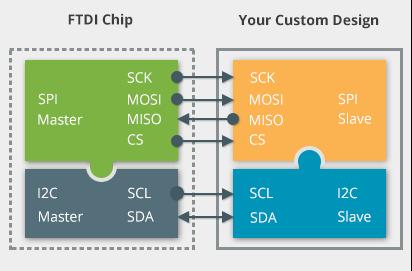
4 1. Introduction 1.1. Definitions and Acronyms MPSSE Multi-Protocol Synchronous Serial Engine RAM Random-Access Memory CS Chip Select GPIO General-Purpose input/output SPI Serial Peripheral Interface CLK Clock Frequency MOSI Master Output, Slave Input 1.2. The Purpose The purpose of this manual is to outline the basics in configuring the MPSSE for use and demonstrate some of the available modes of operation Overview This API provides high-level building blocks to communicate with FTDI Multi- Protocol Synchronous Serial Engine based on D2XX and FT4222H drivers. The API enables users to write applications and communicate with the FTDI Chip s I2C/SPI/JTAG/GPIO devices without needing to understand the low-level D2XX and FT4222 drivers and theirs command sets. MPSSE provides a flexible means of interfacing synchronous serial devices to a USB port. Being Multi-Protocol, the MPSSE allows communication with many different types of synchronous devices; the most popular are SPI and I2C. Data formatting and clock synchronization can be configured in a variety of ways to satisfy almost any requirement. In addition to the serial data pins, additional GPIO signals are available. The API support Windows and NI Linux RT. The Linux version of LibFT4222 has D2XX built-in. The FT4222H supports 4 operation modes to allow various I2C/SPI devices to be connected to USB bus. The attachable device configuration for each mode is listed below: Mode 0 (2 USB interfaces): SPI master, SPI slave, I2C master, or I2C slave device GPIO device Mode 1 (4 USB interfaces): SPI master connects up to 3 SPI slave devices GPIO device Mode 2 (4 USB interfaces): SPI master connects up to 4 SPI slave devices Mode 3 (1 USB interface): SPI master, SPI slave, I2C master, or I2C slave device In mode 0 and 3 the connected device can be a SPI/I2C master or slave, depending on how an application developer initializes the FT4222H chip. Mode 1 and mode 2 are designed to connect to multiple SPI slave devices. The FT4222H can be configured with up to 4 GPIO pins for user applications in mode 0 and mode 1, but each pin is multiplexed with interrupt/suspend out/spi slave select/i2c functions as listed below: gpio0 / ss1o / scl 4

5 gpio1 / ss2o / sda gpio2 / ss3o / suspend out gpio3 / wakeup/intr If the FT4222H is initialized as I2C device, with pins as mentioned above, the pins of gpio0 and gpio1 will be switched to scl and sda, and cannot be used as GPIO. The pin for gpio2 is by default configured as suspend out, and the pin for gpio3 is configured as wakeup/intr. Only these configured GPIO pins can support GPIO read/set operation through the corresponding endpoint. 2. Transfer Library and License Files to NI Linux Real-Time There are many ways of transferring.so and license files to NI Linux RT. For example SSH, WebDAV and FileZilla. The NI Linux Real-Time OS offers full Linux shell support so you can perform complex administrative tasks to manage real-time targets more easily. To access the shell, you need a terminal client. If you use Windows 7 and later, then PuTTY is a popular and free client. In addition to a terminal client, you must select the Enable Secure Shell Server (sshd) option on the real-time target running the NI Linux Real-Time OS. You can use NI Measurement & Automation Explorer (MAX). NI real-time targets support WebDAV file transfer. WebDAV is an industry-standard protocol that is based on top of HTTP. You can easily secure it to transfer libft4222.so and FTDI_license.ini files. WebDAV is the default file transfer mechanism for real-time targets running NI Linux Real-Time. After installing package you can find the libft4222.so library in C:\Program Files (x86)\national Instruments\LabVIEW 2013\vi.lib\Ovak Technologies\FTDI API for LabVIEW\Supporting files path. We recommend to transfer these library and FTDI_license.ini files to /usr/local/lib/ then reboot the controller. For deployment license you need target's Serial Number. 3. How to use FTDI API for Serial Communication Protocols FTDI API is installed under Instrument I/O palette. The palette consists of high-level MPSSE Polymorphic VIs D2XX Drivers and FT4222H library sub palette with lowlevel VIs for D2XX and FT4222H driver call. Figure 1 FTDI Driver API for Serial Communication Protocol (SPI, I2C) 5
6 3.1. Open.vi Use Open.vi to configure the FTDI MPSSE for SPI I2C or JTAG protocols. Just select Device ->Serial Protocol->Connection from Polymorphic drop-down menu. Note: The MPSSE always acts as a master controller for the selected synchronous interface. Figure 2 FT2232H_SPI Figure 3 Configure SPI.vi This VI configures the FTDI MPSSE for SPI protocol. Sets the SPI CLK Frequency, SPI Mode (only Mod0 and Mod2 are supported) and CS pins for slave device. The MPSSE can be placed in loop-back mode for diagnostic purposes (data transmitted out of the DO pin, is also internally connected to the DI pin). Note: The MPSSE always acts as a master controller for the selected synchronous interface. Figure 4 SPI - Multi Slaves.vi This VI configures the FTDI MPSSE for SPI protocol. Sets the SPI CLK Frequency, SPI Mode (only Mod0 and Mod2 are supported) and CS pins for slave devices. The MPSSE can be placed in loop-back mode for diagnostic purposes (data is transmitted out of the DO pin, is also internally connected to the DI pin). This VI should be used when multiple slaves are connected to the bus. Figure 5 Configure I2C.vi This VI configures the FTDI MPSSE for I2C protocol. It sets the I2C CLK Frequency. Registers the I2C Slave Device Address (7-bit address) interconnected to the bus. 6
 interconnected to the bus. This VI should be used when multiple slaves are connected to the bus. 3.2. Write-Read.")
7 Figure 6 Configure I2C - Multi Slaves.vi This VI configures the FTDI Multi-Protocol Synchronous Serial Engine (MPSSE) for I2C protocol. It sets the I2C CLK Frequency. Registers the I2C Slave Device Address (7-bit address) interconnected to the bus. This VI should be used when multiple slaves are connected to the bus Write-Read.vi Performs Write/Read operations according to serial protocol you specify. The instances of this polymorphic VI specify the data format to operate with, as well as a single or multiple slaves are used on bus topology. Figure 7 SPI_Single Slave Figure 8 SPI_SingleSlave_ByteData.vi This VI performs a full-duplex transfer of data with the slave device. In this case, data ("Write Data" bytes) is both sent to the slave and received from the slave at once. Figure 9 SPI_MultipleSlaves_ByteData.vi This VI performs a full-duplex transfer of data with the slave devices. In this action, data ("Write Data" bytes) is both sent to the slave and received from the slave at once. This VI should be used when multiple slaves are connected to the bus. Figure 10 SPI_MultipleSlaves_BitData.vi This VI performs a full-duplex transfer of data with the slave devices. In this action, data ("Bit Data Out" bits) is both sent to the slave and received from the slave at once. This VI should be used when multiple slaves are connected to the bus. 7
 is both sent to the slave and received from the slave at once. This VI should be used when multiple slaves are connected to the bus.")
8 Figure 11 SPI_ SingleSlave_BitData.vi This VI performs a full-duplex transfer of data with the slave device. In this action, data ("Bit Data Out" bits) is both sent to the slave and received from the slave at once. This VI should be used when multiple slaves are connected to the bus. Figure 12 I2C_MultipleSlaves_ReadWrite.vi This VI performs Combined Read and Write Operations on Multiple I2C Slave Devices. It reads Bytes to Read amount of data from Slave Devices in a chain and sends Write Data to the each I2C Slave Devices. This VI should be used when multiple slaves are connected to the bus. Figure 13 I2C_SingleSlave_ReadWrite.vi This VI performs Combined Read and Write Operations on an I2C Slave Device. It reads a "Bytes to Read" amount of data from the Slave Device. After it sends a "Write Data" to the I2C Slave Device Close.vi Use this VI to close opened session. Figure 14 Close.vi 3.4. D2XX Driver D2XX Driver palette is composed of a low-level VIs for D2XX driver call. Figure 15 D2XX 8
9 4. FT4222H Programming Interface (API) LibFT4222 supports SPI, I2C and GPIO communication using high-level APIs. In addition, it provides chip configuration APIs, such as FT4222_SetClock. After calling FT_Open, the FT4222H is required to be initialized by one of the following initial functions: FT4222_SPIMaster_Init FT4222_SPISlave_Init FT4222_I2CMaster_Init FT4222_I2CSlave_Init FT4222_GPIO_Init The initialization functions help developers to switch the FT4222H into a specific mode. At the end of the application, FT4222_Uninitialize should be called to release allocated resources, before calling FT_Close. All the APIs return FT4222_STATUS, which extends FT_STATUS that is defined in the D2XX driver. FT4222_STATUS defines additional values to report FT4222H specific status FT4222 General Functions The functions listed in this section are system-wise configuration functions Open and Close An application of LibFT4222 should open the device and get a handle for subsequent accesses by calling FT_Open or FT_OpenEx. Both are D2XX API. Please note that the FT4222H assigns different functions to different interfaces. For example, under mode 0, interface A is assigned as SPI or I2C interface, and interface B is assigned as GPIO interface. After finishing using the device, FT_Close should be called to release the device Un-initialize Release allocated resources. FT4222_Uninitialize should be called before calling FT_Close. Figure 16 UnInitialize Set Clock Set the system clock rate. The FT4222H supports 4 clock rates: 80MHz, 60MHz, 48MHz, or 24MHz. By default, the FT4222H runs at 60MHz clock rate. Figure 17 SetClock 9
10 Get Clock Get the current system clock rate. Figure 18 GetClock Set Suspend Out Enable or disable, suspend out, which will emit a signal when FT4222H enters suspend mode. Please note that the suspend-out pin is not available under mode Set Wake up/interrupt Enable or disable wakeup/interrupt. Figure 19 SetSuspendOut Figure 20 SetWakeUP/Interrupt Set Interrupt Trigger Condition Set trigger condition for the pin wakeup/interrupt. Figure 21 SetInterruptTrigger Get Max Transfer Size This function returns the maximum packet size in a transaction. It will be affected by different bus speeds, chip modes, and functions. Figure 22 GetMaxTransferSize Set Event Notification Sets conditions for event notification. An application can use this function to set up conditions which allow a thread to block until one of the conditions is met. Typically, an application will create an event, call this function, and then block on the event. When the conditions are met, the event is set, and the application thread is unblocked. Usually, the event is set to notify the application to check the condition. The application needs to check the condition again before it turns to handle the condition. 10

11 Figure 23 SetEventNotification 4.2. SPI Master Functions The FT4222H can be initialized as an SPI master under all modes. As SPI master, it allows data transfers in three types of bit width: Single SPI transfer Standard data transfer format data is read and written simultaneously. DUAL SPI Transfer/Receive Data is transferred out or received in on 2 SPI lines simultaneously. QUAD SPI Transfer/Receive Data is transferred out or received in on 4 SPI lines simultaneously SPI Master Init Initialize the FT4222H as an SPI master. In order to support various types of SPI slave devices, the FT4222H SPI master is configurable using the following parameters: IO lines: SPI transmission lines. The FT4222H SPI supports single, dual, or quad transmission mode. An application may override this initial selection dynamically using FT4222_SPIMaster_SetLines. For example, commands might be sent in single mode but data transferred in dual or quad mode. Clock divider: SPI clock rate is subject to system clock. The FT4222H SPI clock could be 1/2, 1/4, 1/8, 1/16, 1/32, 1/64, 1/128, 1/256, or 1/512 system clock rate. Clock polarity: Active high or active low. Clock phase: Data is sampled on the leading (first) or trailing (second) clock edge. Slave selection output pins: Select slave devices by ss0o, ss1o, ss2o, ss3o. The FT4222H supports active low only. Please note that the FT4222H has only one SPI controller. Though the FT4222H provides up to 4 interfaces for connecting up to 4 SPI slave devices and 4 slave devices share the same SPI data bus: MOSI, MISO, and SCK. A user can decide how to map the 4 interfaces to the 4 SS signals (ss0o, ss1o, ss2o and ss3o) by the ssomap parameter. For example: a. interface 0 for ss0o and ss1o b. interface 1 for ss2o c. interface 2 for ss3o d. interface 3 is not used The 4 interfaces cannot work simultaneously because there is only one data bus. Figure 24 SPIMasterInit 11
12 SPI Master Set Lines Switch the FT4222H SPI master to single, dual, or quad mode. This overrides the mode passed to FT4222_SPIMaster_init. This might be needed if a device accepts commands in single mode but data transfer should use dual or quad mode. Figure 25 SPIMasterSetLines SPI Master Single Read Under SPI single mode, read data from SPI slave. Figure 26 SPIMasterSingleRread SPI Master Single Write Under SPI single mode, write data to SPI slave. Figure 27 SPIMasterSingleWrite SPI Master Single Read and Write Under SPI single mode, full-duplex write data to and read data from SPI slave. The standard SPI protocol simultaneously sends data onto the MOSI data line and receives data from the MISO line. Figure 28 SPIMasterSingleReadWrite 12

13 SPI Master Multi Read and Write Under SPI dual or quad mode, write data to and read data from SPI slave. The dual-spi protocol supported by the FT4222H SPI master is a mixed protocol initiated with a single write transmission, which may be an SPI command and dummy cycles, and followed by dual-write and dual-read transmission that use 2 signals in parallel for the data. All three parts of the protocol are optional. For example, developers can ignore the multi-read part by setting multireadbytes=0. The Quad-SPI protocol supported by the FT4222H SPI master is the same as the dual-protocol. It is a mixed protocol initiated with a single write transmission and followed by quad-write and quad-read transmission that use 4 signals in parallel for the data. Figure 29 SPIMasterMultiReadWrite 4.3. SPI Slave Functions The FT4222H can be initialized as an SPI slave under mode 0 to mode 3. As SPI slave, the FT4222H supports only the standard single SPI transfer. A USB-SPI bridge usually faces the challenge that USB cannot guarantee the throughput for each endpoint, but SPI requires data transmission at a steady rate. It is highly possible when an SPI master starts to request data from a USB-SPI slave bridge device, the data has not arrived from the USB host side yet. In addition, SPI does not have a standard protocol to allow the master side to check the status of the slave side. The protocol is usually provided by an SPI slave device on its own, which makes the SPI master device communicate with the slave device by its specified commands. The FT4222H and LibFT4222 design have implemented an SPI slave protocol which must be used to handle the integrity of data transmission. It starts with Sync word: 0x5A, and followed by a Command field: SPI Slave Init Initializes the FT4222H as SPI slave SPI Slave Get Rx Status Gets number of bytes in the receive queue. Figure 30 SPISlaveInit Figure 31 SPISlaveInit 13

14 SPI Slave Read Reads data from the receive queue of the SPI slave device. Figure 32 SPISlaveRead SPI Slave Write Writes data to the transmits queue of the SPI slave device SPI General Functions SPI Reset Transaction Resets the SPI transaction. Figure 33 SPISlaveWrite SPI Reset Resets the SPI master or slave device. Figure 34 SPIResetTransaction Figure 35 SPIReset SPI Set Driving Strength For the FT4222H SPI, sets the driving strength of clk, io, and sso pins. Figure 36 SPISetDrivingStrength 14
15 4.5. I2C Master Functions I2C (Inter Integrated Circuit) is a multi-master serial bus invented by Philips. I2C uses two bidirectional open-drain wires called serial data (SDA) and serial clock (SCL). Common I²C bus speeds are the 100 kbit/s standard mode (SM), 400 kbit/s fast mode (FM), 1 Mbit/s Fast mode plus (FM+), and 3.4 Mbit/s High Speed mode (HS) The FT4222H device can be initialized as either an I2C master or I2C slave under mode 0 and mode 3. Here is a brief overview of FT4222H I2C features: Fully compatible to I2C v2.1 and v3 specification. 7-bit address support. Support 4 speed configurations: 100KHz(SM), 400KHz(FM), 1MHz(FM+), and 3.4MHz(HS). Clock stretching support in both master and slave mode I2C Master Init Initializes the FT4222H as an I2C master with the requested I2C speed. Figure 37 I2CMasterInit I2C Master Read Reads data from the specified I2C slave device with START and STOP conditions. Figure 38 I2CMasterRead I2C Master Write Writes data to the specified I2C slave device with START and STOP conditions. Figure 39 I2CMasterWrite I2C Master Write Extension Reads data from the specified I2C slave device with the specified I2C condition. Figure 40 I2CMasterReadEx 15
16 I2C Master Read Extension Reads data from the specified I2C slave device with the specified I2C condition. Figure 41 I2CMasterReadEx I2C Master GetStatus Reads the status of the I2C master controller. This can be used to poll a slave until its writecycle is complete. Figure 42 I2CMasterGetStatus I2C Master Reset Resets the I2C master device. If the I2C bus encounters errors or works abnormally, this function will reset the I2C device. It is not necessary to call I2CMaster_Init again after calling this reset function. Figure 43 I2CMasterReset 4.6. I2C Slave Functions The FT4222H device can be initialized as an I2C slave under mode 0 and mode 3. It conforms to v2.1 and v3.0 of the I2C specification and supports all the transmission modes: Standard, Fast, Fast-plus and High Speed. When the I2C slave receives data from the I2C bus, it will keep the data in its internal receive buffer (256 bytes), and then send the data to the USB host through IN packets. When data is requested by an I2C master, data will be moved from an OUT packet to the transmit register directly I2C Slave Init Initializes FT4222H as I2C slave I2C Slave Get Address Gets the address of the I2C slave device. Figure 44 I2CSlaveInit Figure 45 I2CSlaveGetAddress 16
17 I2C Slave Set Address Sets the address of the I2C slave device I2C Slave Get Rx Status Gets number of bytes in the receive queue. Figure 46 I2CSlaveSetAddress Figure 47 I2CSlaveGetRxStatus I2C Slave Read Reads data from the buffer of the I2C slave device I2C Slave Write Writes data to the buffer of I2C slave device. Figure 48 I2CSlaveRead I2C Slave Reset Resets the I2C slave device. Figure 49 I2CSlaveWrite Figure 50 I2CSlaveReset 17
18 4.7. GPIO Functions The FT4222H contains 4 GPIO. When the USB GPIO interface is supported, chip mode 0 and mode 1, LibFT4222 helps application developers to control GPIO directly. However, each GPIO pin is multiplexed with interrupt/suspend out/spi slave select/i2c functions as listed below: gpio0 / ss1o / scl gpio1 / ss2o / sda gpio2 / ss3o / suspend out gpio3 / wakeup/intr The number of GPIO pins available depends on the mode of the chip. For example, if the FT4222H is initialized as an I2C device, as shown above, the pins of gpio0 and gpio1 will be switched to scl and sda, and cannot be used as GPIO. If suspend out and remote wakeup are enabled gpio2 and gpio3 cannot be used as GPIO. The FT4222H supports GPIO on the second USB interface in mode 0 or on the fourth interface in mode 2 (Please refer table 2.1 for chip mode and interface) GPIO Init Initializes the GPIO interface of the FT4222H. Please note the GPIO interface is available on the 2nd USB interface in mode 0 or on the 4th USB interface in mode GPIO Read Reads the value from the specified GPIO pin. Figure 51 GPIOInit GPIO Write Writes value to the specified GPIO pin. Figure 52 GPIORead Figure 53 GPIOWrite 18
19 GPIO Set Input Trigger Set software trigger conditions on the specified GPIO pin. This function allows developers to monitor value changes of the GPIO pins. Values that satisfy the trigger condition will be stored in a queue. For example, if GPIO_TRIGGER_RISING is set on GPIO0, and GPIO0 then changes value from 0 to 1, the event GPIO_TRIGGER_RISING will be recorded into the queue. Developers can query the queue status by FT4222_GPIO_GetTriggerStatus, and FT4222_GPIO_ReadTriggerQueue GPIO Get Trigger Status Gets the size of trigger event queue. Figure 54 GPIOSetInputTriggers Figure 55 GPIOGetTriggerStatus GPIO Read Trigger Queue Gets events are recorded in the trigger event queue. Trigger conditions are set by a call to FT4222_GPIO_SetInputTrigger. After calling this function, all events will be removed from the event queue. 5. Examples Figure 56 GPIOReadTriggerQueue The package installs an example VIs into the Example Finder. In order to open VIs using the NI Example Finder, please select "Browse according to Directory Structure" and navigate to the Ovak Technologies folder SPI Single Slave Example Figure 57 SPI - Single Slave Example 19
20 With a single SPI slave device, it is connected with a 1:1 relationship between signals. Some SPI devices do not have both data in and data out signals. For example an analogue to digital converter may not have a MOSI data input, and a digital to analogue converter may not have a MISO data output. The signals on the FTx232D/H chips have internal pull-ups, so they may be left unconnected if they are not used. The CS signal is used to enable the slave device s interface. With only one device, it may be acceptable to tie the chip select to always-active state. Figure 58 SPI Single Slave Example SPI Single Slave example VI implements a Single Slave SPI bus connection. It performs a full-duplex transfer of data with the slave device. Data (an array of bytes) is both sent to the slave and received from the slave at once SPI Multiple Slaves Example Circuit Figure 59 SPI - Multiple Slaves Example Circuit 20

21 Multiple SPI slaves share data in, data out and clock signals; however, each requires a unique CS signal. Any of the available GPIO signals, in addition to the MPSSE CS signal can be used as additional chip selects. In this case only one slave device can be active. The application program must keep track of which SPI slave device is enabled. As with the single-slave connection, unused DIO signals can be left unconnected. Figure 60 SPI Multiple Slaves Example SPI Multiple Slaves example VI implements a Multiple Slave SPI bus connection. It performs a full-duplex transfer of data with the slave devices. Data is both sent to the slave and received from the slave at once. For applications those have uncommon register sizes (not a multiple of 8 bits), Bit Data mode can be selected from Write-Read.vi Polymorphic VI s drop-down menu FT4222 SPI Master Example Initializes device s clock, mode, and strengths. Builds buffers, sends to SPI Slave and reads received buffers and uninitializes. Figure 61 FT4222 SPI Master Example 21

22 5.4. FT4222 SPI Slave Example Initializes device. When buffer is received it reads and displays. Then it uninitializes and closes all references. Figure 62 FT4222 SPI slave Example 5.5. I2C Single Slave Example Circuit Figure 63 I2C - Single Slave Example Circuit I2C is a bidirectional, half-duplex communication scheme. Although the full specification allows for multiple-masters, the MPSSE can only interface with I2C slave devices. The I2C interface can be implemented with the connection shown in Figure above In addition, the application software will need to include steps to change the direction of the MPSSE DO signal in order to eliminate any bus contention. Figure 64 I2C Single Slave Example I2C Single Slave example VI implements a combined write and read operations in a single slave I2C bus configuration. 22


23 5.6. I2C Multiple Slaves As an extension of the single-slave connection above, multiple I2C slave devices can be connected in parallel. As before, only I2C slave devices can be used and the MPSSE DO signal will require changes in direction to eliminate bus contention. Figure 65 I2C Multiple Slaves I2C Single Slave example VI implements a combined write and read operations in multiple slaves I2C bus configuration FT4222 I2C Master Example Opens connection to I2C slave and initializes master. Sends buffer to I2C slave. Reads buffer from I2C slave, uninitializes and closes connection. Figure 66 I2C Master Example 5.8. FT4222 I2C Slave Example Opens connection port, initializes slave and sets slave address. Get Rx Status for reading received buffer. Reads received buffer and sends received data to master. Unitializes slave and close connection. 23
 At")
24 Figure 67 I2C Slave Example 6. System Requirements FTDI API for Serial Communication Protocols has the following system requirements: LabVIEW 2015 Base, Full, or Professional Development System or later (32-bit or 64- bit) At least 250 MB of disk space 1 GB of RAM FTDI API for Serial Communication Protocols supports the following operating systems: Windows 10 (32-bit or 64-bit) Windows 8 (32-bit or 64-bit) Windows 7 (32-bit or 64-bit), including the Starter Edition (32-bit) NI Linux RT Use of the MPSSE requires installed components, both software and hardware: FTDI FT series device with the MPSSE At the time of publication, FTDI manufactures three devices with the MPSSE block: o FT2232D USB 2.0 Full-Speed Dual UART/FIFO with a single MPSSE (6Mbps, maximum) o FT2232H USB 2.0 Hi-Speed Dual UART/FIFO with two MPSSEs (30Mbps each, maximum) o FT4232H USB 2.0 Hi-Speed Quad UART with two MPSSEs (30Mbps each, maximum) FTDI D2XX Device Drivers o The latest D2XX device drivers are required. Multiple operating systems are supported. See for the latest downloads. Installation guides for various operating systems are available on the FTDI Website. FTDI LibFT4222H. The latest LibFT4222 library are required. Multiple operating systems are supported. 24
25 Documentation o Datasheet for the FTDI FT-series device with the MPSSE o D2XX Programmers Guide o AN_108 Command Processor for MPSSE and MCU Host Bus Emulation Modes 7. Suggested connections Each type of interface has some unique circuitry requirements. With such a diverse selection of peripheral devices, not every interface can be covered here. The implementations below ill serve as a starting point for each popular interfaces. For the FTDI USB Hi-Speed devices (FT2232H and FT4232H), the I/O interface operates at 3.3V. The pins are 5V-tolerant, so it is possible to directly connect 5V devices to the interface. For the FTDI USB Full-Speed device (FT2232D), the I/O interface operates at the voltage applied to VCCIO. Note: Care should be taken to review all datasheets for the devices to ensure I/O threshold and maximum voltages are met. 8. Support Information For technical support, please, contact Ovak Technologies at: Phone: support@ovaktechnologies.com Web: 25
or between microcontrollers)
") : Communication Interfaces in Embedded Systems (e.g., to interface with sensors and actuators or between microcontrollers) Spring 2016 : Communication Interfaces in Embedded Systems Spring (e.g., 2016
: Communication Interfaces in Embedded Systems (e.g., to interface with sensors and actuators or between microcontrollers) Spring 2016 : Communication Interfaces in Embedded Systems Spring (e.g., 2016
Design and development of embedded systems for the Internet of Things (IoT) Fabio Angeletti Fabrizio Gattuso
 Fabio Angeletti Fabrizio Gattuso") Design and development of embedded systems for the Internet of Things (IoT) Fabio Angeletti Fabrizio Gattuso Microcontroller It is essentially a small computer on a chip Like any computer, it has memory,
Design and development of embedded systems for the Internet of Things (IoT) Fabio Angeletti Fabrizio Gattuso Microcontroller It is essentially a small computer on a chip Like any computer, it has memory,
Microcontrollers and Interfacing
 Microcontrollers and Interfacing Week 10 Serial communication with devices: Serial Peripheral Interconnect (SPI) and Inter-Integrated Circuit (I 2 C) protocols College of Information Science and Engineering
Serial Peripheral Interface. What is it? Basic SPI. Capabilities. Protocol. Pros and Cons. Uses
 Serial Peripheral Interface What is it? Basic SPI Capabilities Protocol Serial Peripheral Interface http://upload.wikimedia.org/wikipedia/commons/thumb/e/ed/ SPI_single_slave.svg/350px-SPI_single_slave.svg.png
Future Technology Devices International Ltd UMFT4222EV. USB2.0 to QuadSPI/I2C Bridge Development Module Datasheet
 Future Technology Devices International Ltd UMFT4222EV USB2.0 to QuadSPI/I2C Bridge Development Module Datasheet Neither the whole nor any part of the information contained in, or the product described
< W3150A+ / W5100 Application Note for SPI >
 < W3150A+ / W5100 Application Note for SPI > Introduction This application note describes how to set up the SPI in W3150A+ or W5100. Both the W3150A+ and W5100 have same architecture. W5100 is operated
Introduction to I2C & SPI. Chapter 22
 Introduction to I2C & SPI Chapter 22 Issues with Asynch. Communication Protocols Asynchronous Communications Devices must agree ahead of time on a data rate The two devices must also have clocks that are
Raspberry Pi - I/O Interfaces
 ECE 1160/2160 Embedded Systems Design Raspberry Pi - I/O Interfaces Wei Gao ECE 1160/2160 Embedded Systems Design 1 I/O Interfaces Parallel I/O and Serial I/O Parallel I/O: multiple input/output simultaneously
Universität Dortmund. IO and Peripheral Interfaces
 IO and Peripheral Interfaces Microcontroller System Architecture Each MCU (micro-controller unit) is characterized by: Microprocessor 8,16,32 bit architecture Usually simple in-order microarchitecture,
Part 1 Using Serial EEPROMs
 Part 1 Using Serial EEPROMs copyright 1997, 1999 by Jan Axelson If you have a project that needs a modest amount of nonvolatile, read/write memory, serial EEPROM may be the answer. These tiny and inexpensive
Read section 8 of this document for detailed instructions on how to use this interface spec with LibUSB For OSX
 CP2130 INTERFACE SPECIFICATION 1. Introduction The Silicon Labs CP2130 USB-to-SPI bridge is a device that communicates over the Universal Serial Bus (USB) using vendor-specific control and bulk transfers
Future Technology Devices International Ltd. FT4222H
 Future Technology Devices International Ltd. FT4222H (USB2.0 to QuadSPI/I 2 C Bridge IC) FT4222H is a USB2.0 to Quad-SPI/I 2 C interface Device Controller with the following advanced features: Single chip
AT90SO72 Summary Datasheet
 AT90SO Summary Datasheet Features General High-performance, Low-power -/-bit Enhanced RISC Architecture Microcontroller - Powerful Instructions (Most Executed in a Single Clock Cycle) Low Power Idle and
McMaster University Embedded Systems. Computer Engineering 4DS4 Lecture 6 Serial Peripherals Amin Vali Feb. 2016
 McMaster University Embedded Systems Computer Engineering 4DS4 Lecture 6 Serial Peripherals Amin Vali Feb. 2016 Serial Peripherals I2C Inter-IC Bus X/Y Coord. RGB data LCD config controller LCD data controller
Development and research of different architectures of I 2 C bus controller. E. Vasiliev, MIET
 Development and research of different architectures of I 2 C bus controller E. Vasiliev, MIET I2C and its alternatives I²C (Inter-Integrated Circuit) is a multi-master serial computer bus invented by Philips
HZX N03 Bluetooth 4.0 Low Energy Module Datasheet
 HZX-51822-16N03 Bluetooth 4.0 Low Energy Module Datasheet SHEN ZHEN HUAZHIXIN TECHNOLOGY LTD 2017.7 NAME : Bluetooth 4.0 Low Energy Module MODEL NO. : HZX-51822-16N03 VERSION : V1.0 1.Revision History
Microcontroller basics
 FYS3240 PC-based instrumentation and microcontrollers Microcontroller basics Spring 2017 Lecture #4 Bekkeng, 30.01.2017 Lab: AVR Studio Microcontrollers can be programmed using Assembly or C language In
Interfacing Techniques in Embedded Systems
 Interfacing Techniques in Embedded Systems Hassan M. Bayram Training & Development Department training@uruktech.com www.uruktech.com Introduction Serial and Parallel Communication Serial Vs. Parallel Asynchronous
Parallel Data Transfer. Suppose you need to transfer data from one HCS12 to another. How can you do this?
 Introduction the Serial Communications Huang Sections 9.2, 10.2, 11.2 SCI Block User Guide SPI Block User Guide IIC Block User Guide o Parallel vs Serial Communication o Synchronous and Asynchronous Serial
Growing Together Globally Serial Communication Design In Embedded System
 Growing Together Globally Serial Communication Design In Embedded System Contents Serial communication introduction......... 01 The advantages of serial design......... 02 RS232 interface......... 04 RS422
SPI Universal Serial Communication Interface SPI Mode
 SPI Universal Serial Communication Interface SPI Mode Serial Peripheral Interface (SPI) is not really a protocol, but more of a general idea. It s the bare-minimum way to transfer a lot of data between
Future Technology Devices International Ltd. TN_161 FT4222H Errata Technical Note
 Future Technology Devices International Ltd TN_161 FT4222H Errata Technical Note Issue Date: 2018-03-28 The intention of this errata technical note is to give a detailed description of known functional
Technical Note TN_107
 Future Technology Devices International Ltd. Technical Note TN_107 FTDI Chipset Feature Comparison Document Reference No.: FT_000108 Issue Date: 2008-12-08 This technical note compares several FTDI devices
Serial Buses in Industrial and Automotive Applications
 Serial Buses in Industrial and Automotive Applications Presented by Neelima Chaurasia Class: #368 1 Overview As consumer electronics, computer peripherals, vehicles and industrial applications add embedded
Real-Time Embedded Systems. CpE-450 Spring 06
 Real-Time Embedded Systems CpE-450 Spring 06 Class 5 Bruce McNair bmcnair@stevens.edu 5-1/42 Interfacing to Embedded Systems Distance 100 m 10 m 1 m 100 cm 10 cm "Transmission line" capacitance ( C) Distance
Serial Communication. Simplex Half-Duplex Duplex
 1.5. I/O 128 Serial Communication Simplex Half-Duplex Duplex 129 Serial Communication Master-Slave Master Master-Multi-Slave Master Slave Slave Slave (Multi-)Master Multi-Slave Master Slave Slave Slave
Introduction the Serial Communications Parallel Communications Parallel Communications with Handshaking Serial Communications
 Introduction the Serial Communications Parallel Communications Parallel Communications with Handshaking Serial Communications o Asynchronous Serial (SCI, RS-232) o Synchronous Serial (SPI, IIC) The MC9S12
Amarjeet Singh. January 30, 2012
 Amarjeet Singh January 30, 2012 Website updated - https://sites.google.com/a/iiitd.ac.in/emsys2012/ Lecture slides, audio from last class Assignment-2 How many of you have already finished it? Final deadline
Network Embedded Systems Sensor Networks Fall Hardware. Marcus Chang,
 Network Embedded Systems Sensor Networks Fall 2013 Hardware Marcus Chang, mchang@cs.jhu.edu 1 Embedded Systems Designed to do one or a few dedicated and/or specific functions Embedded as part of a complete
Pmod modules are powered by the host via the interface s power and ground pins.
 1300 Henley Court Pullman, WA 99163 509.334.6306 www.store. digilent.com Digilent Pmod Interface Specification 1.2.0 Revised October 5, 2017 1 Introduction The Digilent Pmod interface is used to connect
Arduino Uno R3 INTRODUCTION
 Arduino Uno R3 INTRODUCTION Arduino is used for building different types of electronic circuits easily using of both a physical programmable circuit board usually microcontroller and piece of code running
BLE 1.4 SPI Driver Design Version 1.x (Draft)
") BLE 1.4 SPI Driver Design Version 1.x (Draft) Document Number: TBD TABLE OF CONTENTS 1. FUNCTIONAL OVERVIEW... 1 2. DEFINITIONS, ABBREVIATIONS, ACRONYMS... 2 3. REVISION HISTORY... 2 4. SPI INTERFACE...
BLE 1.4 SPI Driver Design Version 1.x (Draft) Document Number: TBD TABLE OF CONTENTS 1. FUNCTIONAL OVERVIEW... 1 2. DEFINITIONS, ABBREVIATIONS, ACRONYMS... 2 3. REVISION HISTORY... 2 4. SPI INTERFACE...
Serial Communication. Simplex Half-Duplex Duplex
 1.5. I/O 135 Serial Communication Simplex Half-Duplex Duplex 136 Serial Communication Master-Slave Master Master-Multi-Slave Master Slave Slave Slave (Multi-)Master Multi-Slave Master Slave Slave Slave
More on IO: The Universal Serial Bus (USB)
") ecture 37 Computer Science 61C Spring 2017 April 21st, 2017 More on IO: The Universal Serial Bus (USB) 1 Administrivia Project 5 is: USB Programming (read from a mouse) Optional (helps you to catch up
ecture 37 Computer Science 61C Spring 2017 April 21st, 2017 More on IO: The Universal Serial Bus (USB) 1 Administrivia Project 5 is: USB Programming (read from a mouse) Optional (helps you to catch up
AT-501 Cortex-A5 System On Module Product Brief
 AT-501 Cortex-A5 System On Module Product Brief 1. Scope The following document provides a brief description of the AT-501 System on Module (SOM) its features and ordering options. For more details please
AT90SO36 Summary Datasheet
 AT90SO Summary Datasheet Features General High-performance, Low-power -/-bit Enhanced RISC Architecture Microcontroller - Powerful Instructions (Most Executed in a Single Clock Cycle) Low Power Idle and
Prototyping Module Datasheet
 Prototyping Module Datasheet Part Numbers: MPROTO100 rev 002 Zenseio LLC Updated: September 2016 Table of Contents Table of Contents Functional description PROTOTYPING MODULE OVERVIEW FEATURES BLOCK DIAGRAM
Nano RK And Zigduino. wnfa ta course hikaru4
 Nano RK And Zigduino wnfa ta course hikaru4 Today's outline Zigduino v.s. Firefly Atmel processor and the program chip I/O Interface on the board Atmega128rfa1, FTDI chip... GPIO, ADC, UART, SPI, I2C...
Module Introduction. PURPOSE: The intent of this module, is to explain several of the important features of Freescale s i.mx1 applications processor.
 Module Introduction PURPOSE: The intent of this module, is to explain several of the important features of Freescale s i.mx1 applications processor. OBJECTIVES: - Describe the features and functions of
Technical Note TN_175 FT4222H Revision D
 TN_175 FT4222H Revision D Issue Date: 2018-04-03 The intention of this technical note is to give a detailed description of improvement available in the FT4222H Revision D device. The current revision of
SKB360I Bluetooth 4.0 Low Energy Module Datasheet
 SKB360I Bluetooth 4.0 Low Energy Module Datasheet Name: Bluetooth 4.0 Low Energy Module Model No.: SKB360I Version: V1.01 Revision History: Revision Description Approved Date V1.01 Initial Release Hogan
Serial Communications
 1 Serial Interfaces 2 Embedded systems often use a serial interface to communicate with other devices. Serial Communications Serial implies that it sends or receives one bit at a time. Serial Interfaces
EE 456 Fall, Table 1 SPI bus signals. Figure 1 SPI Bus exchange of information between a master and a slave.
 EE 456 Fall, 2009 Notes on SPI Bus Blandford/Mitchell The Serial Peripheral Interface (SPI) bus was created by Motorola and has become a defacto standard on many microcontrollers. This is a four wire bus
ArduCAM-M-2MP Camera Shield
 33275-MP ArduCAM-M-2MP Camera Shield 2MP SPI Camera Hardware Application Note Rev 1.0, Mar 2015 33275-MP ArduCAM-M-2MP Hardware Application Note Table of Contents 1 Introduction... 2 2 Typical Wiring...
Introduction the Serial Communications Huang Sections 9.2, 10.2 SCI Block User Guide SPI Block User Guide
 Introduction the Serial Communications Huang Sections 9.2,.2 SCI Block User Guide SPI Block User Guide Parallel Data Transfer Suppose you need to transfer data from one HCS2 to another. How can you do
RL78 Serial interfaces
 RL78 Serial interfaces Renesas Electronics 00000-A Introduction Purpose This course provides an introduction to the RL78 serial interface architecture. In detail the different serial interfaces and their
Serial Communication. Spring, 2018 Prof. Jungkeun Park
 Serial Communication Spring, 2018 Prof. Jungkeun Park Serial Communication Serial communication Transfer of data over a single wire for each direction (send / receive) Process of sending data one bit at
C8051F700 Serial Peripheral Interface (SPI) Overview
 Overview") C8051F700 Serial Peripheral Interface (SPI) Overview Agenda C8051F700 block diagram C8051F700 device features SPI operation overview SPI module overview Where to learn more 2 Introducing The C8051F700
C8051F700 Serial Peripheral Interface (SPI) Overview Agenda C8051F700 block diagram C8051F700 device features SPI operation overview SPI module overview Where to learn more 2 Introducing The C8051F700
ECE Microcontrollers. Serial Peripheral Interface (SPI) & NRF24 Radio
 & NRF24 Radio") ECE 381 - Microcontrollers Serial Peripheral Interface (SPI) & NRF24 Radio Lab 9 Summary We will develop a wireless temperature sensor Once a second, sample LM34CZ voltage Convert to floating point with
ECE 381 - Microcontrollers Serial Peripheral Interface (SPI) & NRF24 Radio Lab 9 Summary We will develop a wireless temperature sensor Once a second, sample LM34CZ voltage Convert to floating point with
Working with Quad and Other SPI Protocols Testing and Debugging (Quad-) SPI-based ASIC, FPGA, SoC and Embedded Systems
 SPI-based ASIC, FPGA, SoC and Embedded Systems") Working with Quad and Other SPI Protocols Testing and Debugging (Quad-) SPI-based ASIC, FPGA, SoC and Embedded Systems By Alan Lowne, CEO, SaeligCo., Inc. and Frédéric Leens, sales and marketing manager,
Working with Quad and Other SPI Protocols Testing and Debugging (Quad-) SPI-based ASIC, FPGA, SoC and Embedded Systems By Alan Lowne, CEO, SaeligCo., Inc. and Frédéric Leens, sales and marketing manager,
Digital Storage Oscilloscope
 Digital Storage Oscilloscope GDS-3000 Series SERIAL DECODE MANUAL GW INSTEK PART NO. 82DS-SBD00U01 ISO-9001 CERTIFIED MANUFACTURER October 2010 This manual contains proprietary information, which is protected
Groking the Linux SPI Subsystem FOSDEM Matt Porter
 Groking the Linux SPI Subsystem FOSDEM 2017 Matt Porter Obligatory geek reference deobfuscation grok (/gräk/) verb to understand intuitively or by empathy, to establish rapport with. Overview What is SPI?
FT4232H-56Q Mini Module. USB Hi-Speed FT4232H Evaluation Module. Datasheet
 Future Technology Devices International Ltd. FT4232H-56Q Mini Module USB Hi-Speed FT4232H Evaluation Module Datasheet Neither the whole nor any part of the information contained in, or the product described
USB to SPI Bridge. Hardware Manual. Revision 1.0
 USB to SPI Bridge Hardware Manual Revision 1.0 Revision History Revision Date Description Author 1.0 October 11 th, 2017 Initial Release Divino 1 USB to SPI Bridge Contents Revision History... 1 Contents...
Lecture 25 March 23, 2012 Introduction to Serial Communications
 Lecture 25 March 23, 2012 Introduction to Serial Communications Parallel Communications Parallel Communications with Handshaking Serial Communications Asynchronous Serial (e.g., SCI, RS-232) Synchronous
Concepts of Serial Communication
 Section 6. Serial Communication Communication Using Serial Interfaces: UART and SPI Concepts of Serial Communication Limitations of Parallel Bus Clock skew becomes a serious issue for high speed and long
USER GUIDE EDBG. Description
 USER GUIDE EDBG Description The Atmel Embedded Debugger (EDBG) is an onboard debugger for integration into development kits with Atmel MCUs. In addition to programming and debugging support through Atmel
Introduction Electrical Considerations Data Transfer Synchronization Bus Arbitration VME Bus Local Buses PCI Bus PCI Bus Variants Serial Buses
 Introduction Electrical Considerations Data Transfer Synchronization Bus Arbitration VME Bus Local Buses PCI Bus PCI Bus Variants Serial Buses 1 Most of the integrated I/O subsystems are connected to the
1.3inch OLED User Manual
 1.3inch OLED User Manual 1. Key Parameters Table 1: Key Parameters Driver Chip SH1106 Interface 3-wire SPI 4-wire SPI I2C Resolution 128*64 Display Size 1.3 inch Dimension 29mm*33mm Colors Yellow, Blue
PARALLEL COMMUNICATIONS
 Parallel Data Transfer Suppose you need to transfer data from one HCS12 to another. How can you do this? You could connect PORTA of the sending computer (set up as an output port) to PORTA of the receiving
Raspberry Pi. Hans-Petter Halvorsen, M.Sc.
 Raspberry Pi Hans-Petter Halvorsen, M.Sc. Raspberry Pi https://www.raspberrypi.org https://dev.windows.com/iot Hans-Petter Halvorsen, M.Sc. Raspberry Pi - Overview The Raspberry Pi 2 is a low cost, credit-card
EDBG. Description. Programmers and Debuggers USER GUIDE
 Programmers and Debuggers EDBG USER GUIDE Description The Atmel Embedded Debugger (EDBG) is an onboard debugger for integration into development kits with Atmel MCUs. In addition to programming and debugging
FT245 USB Modual. - Ver FT245 Module Features
 1. FT245 Module Features FT245 USB Modual - Ver 1.0 - - FTDI chip 사의 FT245 채용 - D2XX Driver 사용시최대 1MByte 전송 - 1 열 Pin Header 에 Data, Control Pin 입출력 - 외부 I/O 전원선택가능 (3.3V, 5V) - USB 정보저장을위한 EEPROM Socket
I2C and SPI Foundation
 Revision 30 September 2010 Release I2C and SPI Foundation 17 March 2018 changed ref: command f to x Introduction I2C (I squared C) and SPI (Serial peripheral Interface) are two main ways that microcontrollers
Each I2C master has 8-deep transmit and receive FIFOs for efficient data handling. SPI to Dual I2C Masters. Registers
 February 205 Introduction Reference Design RD73 I2C and SPI are the two widely used bus protocols in today s embedded systems. The I2C bus has a minimum pin count requirement and therefore a smaller footprint
Infineon C167CR microcontroller, 256 kb external. RAM and 256 kb external (Flash) EEPROM. - Small single-board computer (SBC) with an
 EEPROM. - Small single-board computer (SBC) with an") Microcontroller Basics MP2-1 week lecture topics 2 Microcontroller basics - Clock generation, PLL - Address space, addressing modes - Central Processing Unit (CPU) - General Purpose Input/Output (GPIO)
Microcontroller Basics MP2-1 week lecture topics 2 Microcontroller basics - Clock generation, PLL - Address space, addressing modes - Central Processing Unit (CPU) - General Purpose Input/Output (GPIO)
CprE 488 Embedded Systems Design. Lecture 4 Interfacing Technologies
 CprE 488 Embedded Systems Design Lecture 4 Interfacing Technologies Joseph Zambreno Electrical and Computer Engineering Iowa State University www.ece.iastate.edu/~zambreno rcl.ece.iastate.edu Never trust
Future Technology Devices International Ltd FT232H Single Channel Hi- Speed USB to Multipurpose UART/FIFO IC
 Future Technology Devices International Ltd FT232H Single Channel Hi- Speed USB to Multipurpose UART/FIFO IC The FT232H is a single channel USB 2.0 Hi- Speed (480Mb/s) to UART/FIFO IC. It has the capability
ARDUINO YÚN MINI Code: A000108
 ARDUINO YÚN MINI Code: A000108 The Arduino Yún Mini is a compact version of the Arduino YUN OVERVIEW: Arduino Yún Mini is a breadboard PCB developed with ATmega 32u4 MCU and QCA MIPS 24K SoC CPU operating
Serial Communications
 Serial Communications p. 1/2 Serial Communications CSEE W4840 Prof. Stephen A. Edwards Columbia University Early Serial Communication Serial Communications p. 2/2 Data Terminal Equipment Serial Communications
ICS Humla CTF. Copyright 2017 Payatu https://www.payatu.com 1
 ICS Humla CTF BY ARUN MANE SR. SECURITY RESEARCHER Copyright 2017 Payatu https://www.payatu.com 1 About Sr. Security Researcher at Payatu Software Labs Focused in IoT, ICS, Vehicle Security Co-Trainer
Using the Z8051 MCU s USI Peripheral as an SPI Interface
 Using the Z8051 MCU s USI Peripheral as an SPI Interface AN035901-0513 Abstract This document describes how to configure Zilog s Z8051 Universal Serial Interface (USI) peripheral to operate as Serial Peripheral
SPI (Serial & Peripheral Interface)
") SPI (Serial & Peripheral Interface) What is SPI SPI is a high-speed, full-duplex bus that uses a minimum of 3 wires to exchange data. The popularity of this bus rose when SD cards (and its variants ie:
SPI (Serial & Peripheral Interface) What is SPI SPI is a high-speed, full-duplex bus that uses a minimum of 3 wires to exchange data. The popularity of this bus rose when SD cards (and its variants ie:
LABORATORIO DI ARCHITETTURE E PROGRAMMAZIONE DEI SISTEMI ELETTRONICI INDUSTRIALI. Laboratory Lesson 9: Serial Peripheral Interface (SPI)
") LABORATORIO DI ARCHITETTURE E PROGRAMMAZIONE DEI SISTEMI ELETTRONICI INDUSTRIALI Laboratory Lesson 9: Serial Peripheral Interface (SPI) Prof. Luca Benini Prof Davide Rossi
LABORATORIO DI ARCHITETTURE E PROGRAMMAZIONE DEI SISTEMI ELETTRONICI INDUSTRIALI Laboratory Lesson 9: Serial Peripheral Interface (SPI) Prof. Luca Benini Prof Davide Rossi
The Serial Peripheral Interface
 (SPI) ARSLAB - Autonomous and Robotic Systems Laboratory Dipartimento di Matematica e Informatica - Università di Catania, Italy santoro@dmi.unict.it L.S.M. 1 Course What is SPI? The SPI Serial Peripheral
Win-I2CUSB Hardware User s Manual
 Win-I2CUSB Hardware User s Manual http://www.demoboard.com Information provided in this document is solely for use with the Win-I2CUSB product from The Boardshop. The Boardshop and SB Solutions, Inc. reserve
1.6inch SPI Module user manual
 1.6inch SPI Module user manual www.lcdwiki.com 1 / 10 Rev1.0 Product Description The 1.6 module is tested using the ESP8266MOD D1 Mini development board, Both the test program and the dependent libraries
A1/B1 EB v2.0 User Manual V1.1 05/10/2017
 A1/B1 EB v2.0 User Manual V1.1 05/10/2017 Table of Contents 1. Device Overview...2 2. Electrical Characteristics...3 2.1 Test Conditions... 3 2.2 Absolute Maximum Ratings... 3 2.3 Operating Conditions...
FTDI Chip VA800A-SPI USB 2.0 Hi-Speed to MPSSE SPI Module
 FTDI Chip VA800A-SPI USB 2.0 Hi-Speed to MPSSE SPI Module 1. Introduction 1.1 Features The USB2.0 Hi-Speed to MPSSE SPI Module, VA800A-SPI, is a small electronic circuit board, utilising the FTDI FT232H.
Arduino Uno. Arduino Uno R3 Front. Arduino Uno R2 Front
 Arduino Uno Arduino Uno R3 Front Arduino Uno R2 Front Arduino Uno SMD Arduino Uno R3 Back Arduino Uno Front Arduino Uno Back Overview The Arduino Uno is a microcontroller board based on the ATmega328 (datasheet).
Level Shifter. for. Hardware User s Manual.
 Level Shifter for USB-to to-i2c Hardware User s Manual https://www.i2ctools.com/ Information provided in this document is solely for use with the I2C and SPI Level Shifter from SB Solutions, Inc. SB Solutions,
Understanding SPI with Precision Data Converters
 Understanding SPI with Precision Data Converters By: Tony Calabria Presented by: 1 Communication Comparison SPI - Serial Peripheral Interface Bus I2C - Inter- Integrated Circuit Parallel Bus Advantages
Generic Serial Flash Interface Intel FPGA IP Core User Guide
 Generic Serial Flash Interface Intel FPGA IP Core User Guide Updated for Intel Quartus Prime Design Suite: 18.0 Subscribe Send Feedback Latest document on the web: PDF HTML Contents Contents 1. Generic
ASNTu2s PCB with Tiger Board USB to 7-Channel 3-Wire Interface Bridge Application Notes
 ASNTu2s PCB with Tiger Board USB to 7-Channel 3-Wire Interface Bridge Application Notes Table of Contents Tiger Board Description... 2 ASNTu2s Description... 2 Software Installation... 3 Bridge and GUI
USB-to-I2C. Professional Hardware User s Manual.
 USB-to-I2C Professional Hardware User s Manual https://www.i2ctools.com/ Information provided in this document is solely for use with the USB-to-I2C Professional product from SB Solutions, Inc. SB Solutions,
EMBEDDED SYSTEMS WITH ROBOTICS AND SENSORS USING ERLANG
 EMBEDDED SYSTEMS WITH ROBOTICS AND SENSORS USING ERLANG Adam Lindberg github.com/eproxus HARDWARE COMPONENTS SOFTWARE FUTURE Boot, Serial console, Erlang shell DEMO THE GRISP BOARD SPECS Hardware & specifications
Color 7 click. PID: MIKROE 3062 Weight: 19 g
 Color 7 click PID: MIKROE 3062 Weight: 19 g Color 7 click is a very accurate color sensing Click board which features the TCS3472 color light to digital converter with IR filter, from ams. It contains
UART TO SPI SPECIFICATION
 UART TO SPI SPECIFICATION Author: Dinesh Annayya dinesha@opencores.org Table of Contents Preface... 3 Scope... 3 Revision History... 3 Abbreviations... 3 Introduction... 3 Architecture... 4 Baud-rate generator
G80 SoC Datasheet. Where Hardware Meets Software
 GHI Electronics, LLC 501 E. Whitcomb Ave. Madison Heights, Michigan 48071 Phone: (248) 397-8856 Fax: (248) 397-8890 www.ghielectronics.com G80 SoC Datasheet Where Hardware Meets Software GHI Electronics,
Using FlexIO to emulate communications and timing peripherals
 NXP Semiconductors Document Number: AN12174 Application Note Rev. 0, 06/2018 Using FlexIO to emulate communications and timing peripherals 1. Introduction The FlexIO is a new on-chip peripheral available
AN_357. Android Java D2xx Demo Application for FT4222
 Future Technology Devices International Ltd. AN_357 Android Java D2xx Demo Application for FT4222 Document Reference No.:FT_001142 Version 1.0 Issue Date: 2015-01-21 This document provides the application
AT90SDC10X Summary Datasheet
 AT90SDC10X Summary Datasheet Features General twincore Secure Dual Core Architecture - 135 Powerful s (Most Executed in a Single Clock Cycle) Total isolation between Master & Secure Cores Secure Inter-Core
Future Technology Devices International
 Future Technology Devices International UMFTPD2A UMFTPD2A is a module used for FT90x programming, debugging and EFUSE burning. The UMFTPD2A is a module with an FT4232HL Hi-Speed USB2.0 to multipurpose
Embedded Systems and Software. Serial Interconnect Buses I 2 C (SMB) and SPI
 and SPI") Embedded Systems and Software Serial Interconnect Buses I 2 C (SMB) and SPI I2C, SPI, etc. Slide 1 Provide low-cost i.e., low wire/pin count connection between IC devices There are many of serial bus standards
Embedded Systems and Software Serial Interconnect Buses I 2 C (SMB) and SPI I2C, SPI, etc. Slide 1 Provide low-cost i.e., low wire/pin count connection between IC devices There are many of serial bus standards
M68HC08 Microcontroller The MC68HC908GP32. General Description. MCU Block Diagram CPU08 1
 M68HC08 Microcontroller The MC68HC908GP32 Babak Kia Adjunct Professor Boston University College of Engineering Email: bkia -at- bu.edu ENG SC757 - Advanced Microprocessor Design General Description The
IV B.Tech. I Sem (R13) ECE : Embedded Systems : UNIT -4 1 UNIT 4
 ECE : Embedded Systems : UNIT -4 1 UNIT 4") IV B.Tech. I Sem (R13) ECE : Embedded Systems : UNIT -4 1 UNIT 4 4.1. Serial data communication basics ----------- 1 4.2. UART ------------------------------------------------ 4 4.3. Serial Peripheral
IV B.Tech. I Sem (R13) ECE : Embedded Systems : UNIT -4 1 UNIT 4 4.1. Serial data communication basics ----------- 1 4.2. UART ------------------------------------------------ 4 4.3. Serial Peripheral
USB-to-I2C. Ultra Hardware User s Manual.
 USB-to-I2C Ultra Hardware User s Manual https://www.i2ctools.com/ Information provided in this document is solely for use with the USB-to-I2C Ultra product from SB Solutions, Inc. SB Solutions, Inc. reserves
VA108x0 SPI memory boot options application note
 AN1205 VA108x0 SPI memory boot options application note Dec 21, 2016 Version 1.0 VA10800/VA10820 Abstract The VA108x0 family of MCUs boot from an external SPI memory then execute code from internal SRAM.
Basics of UART Communication
 Basics of UART Communication From: Circuit Basics UART stands for Universal Asynchronous Receiver/Transmitter. It s not a communication protocol like SPI and I2C, but a physical circuit in a microcontroller,
Product Technical Brief S3C2413 Rev 2.2, Apr. 2006
 Product Technical Brief Rev 2.2, Apr. 2006 Overview SAMSUNG's is a Derivative product of S3C2410A. is designed to provide hand-held devices and general applications with cost-effective, low-power, and