Contents. Peer-to-Host vs. Peer-to-Peer Systems The System Host The Module Types Masters, Slaves, and Masterless Communications...
|
|
|
- Polly Shaw
- 6 years ago
- Views:
Transcription
1
2 Contents Introduction 1 vs. Peer-to-Peer Systems... 1 The System Host... 2 The Module Types Masters, Slaves, and Masterless... 2 Specifications 2 unications... 2 Modules... 3 Throughput... 7 Ordering Information 7 I/O EXPRESS Model Numbers 8 Installation 8 Setting Master/Masterless Baud Rate... 8 Redundant s... 9 Setting the Masterless/Master unications Address... 9 Mounting the I/O EXPRESS on DIN Rail Making Electrical and unications Connections Making Connections to Field Instruments Recommended Ground Wiring Practices Page i (continues)
3 Operation 20 MODBUS Implementation Accessing Masterless Module Data Accessing Slave Module Data Temperature and Analog I/O Data unications Status LEDs and Alarms Fault Flags Complete Systems Customer Support 21 List of Illustrations and Tables Figure 1. Understanding the I/O EXPRESS...1 Figure 2. Setting I/O EXPRESS Module Baud Rate to 2400 (Masters and Masterless Modules ONLY)...8 Figure 3. Setting I/O EXPRESS Module Address (Masters and Masterless Modules ONLY)... 9 Figure 4. Using I/O EXPRESS Redundant Hookups Figure 5. Dimensions of the I/O EXPRESS Housing Figure 6. Installing the I/O EXPRESS Mounting Clips and Locking Tabs Figure 7. Connecting Pairs of I/O EXPRESS Masters (and Masterless Modules), and Slaves to Masters Figure 8. Connecting Multiple Analog Inputs to I/O EXPRESS Slaves or Masterless Modules Figure 9. Connecting Multiple Analog Outputs from I/O EXPRESS Slaves or Masterless Modules to Field Devices Figure 10. Connecting Multiple, Discrete (Digital) Inputs to I/O EXPRESS Slaves or Masterless Modules Figure 11. Connecting Multiple, Discrete (Digital), Open Collector Outputs from I/O EXPRESS Slaves or Masterless Modules to Field Devices Figure 12. Connecting 8 Relay Outputs from I/O EXPRESS Slaves or Masterless Modules to Field Devices Figure 13. Connecting 12 Relay Outputs from I/O EXPRESS Slaves or Masterless Modules to Field Devices Figure 14. Connecting 8 RTD Inputs to I/O EXPRESS Slaves or Masterless Modules to Field Devices Figure 15. Connecting 10 Thermocouple Inputs to I/O EXPRESS Slaves or Masterless Modules to Field Devices Table 1. Setting I/O EXPRESS Module Baud Rate...8 Table 2. Setting I/O EXPRESS Module Address...9 Table 3. I/O EXPRESS Valid MODBUS RTU Function Codes Table 4. I/O EXPRESS Master Module Slave Data Byte Addressing Table 5. I/O EXPRESS Status and Alarm Outputs Page ii
4 Page 1 Introduction I/O EXPRESS is the name given to the family of modules that make up Moore Industries Distributed Data System (DDS). The DDS is a group of interface modules that provides a cost-effective communications link between multiple, dispersed points of input, output and control. Modules serve as everything from platforms for two-way communications between control room computers and analog and/or discrete field devices, to multiplexers that squeeze the signals of more than 7,000 points of input and/or output (I/O) over a single, digital unications ( ). vs. Peer-to-Peer Systems There are two basic types of I/O EXPRESS systems: and Peer-to-Peer. This manual provides information on systems. A Peer to Host I/O Express system relies upon the actions of a Host device to send data and/signals back and forth between points of control and I/O. Figure 1 shows a general overview of a basic I/O EXPRESS. The illustration shows all three types of modules: Masters, Slaves, and Masterless. Peer-to-Peer systems, which operate without Host control, are covered in a separate manual. Contact the factory, or your local Moore Industries Sales rep-resentative for a copy. Figure 1. Understanding the I/O EXPRESS HOST RS-485 CO MM LINKS MASTER MASTERLESS SLAVES NOTE:
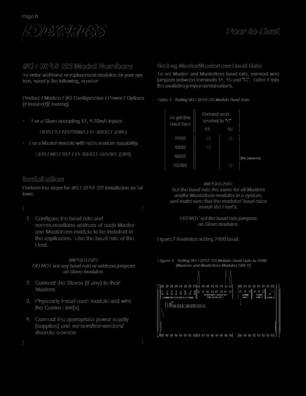
5 Page 2 The System Host In this manual, the term Host refers to the combination of hardware and software used to communicate MODBUS 1 Remote Terminal Unit (MODBUS RTU) queries to connected I/O EXPRESS modules over the system. Typically, a Host is a personal computer (PC), or some similar type of computer-based controller running distributed control (DCS) or super-visory command and data acquisition (SCADA) software. Contact the factory for a list of compatible programs. The Module Types Masters, Slaves, and Masterless Master modules multiplex the signals of up to 12 Slave modules. They do not accommodate field I/O signals directly, but combine the signals from all connected Slaves into a single, digital signal that is communicated to the Host over the. Slave modules take input from, and/or provide output to, field devices. They communicate these signals, in digital form, to Master modules, which then send the data over the to the system Host. Masterless modules take input directly from, and/or provide output directly to field devices. They communicate these signals directly to the Host. Specifications unications * - Half-duplex, digital RS-485 (RS-232 optional) Master-to-Host and Masterless-to-Host. Physical connections may be made over twisted wire pair; fiber optic cabling; dial-up, leased line, or radio modems. Contact the factory, or your Moore Industries Sales representative, for information on Moore Industries line of communications hardware, including modems, -to-fiber and RS 485-to-RS 232 converters. Protocol* - MODBUS RTU for Masters-to-Host and Masterless to-host. Refer to the Operation section of this manual for the valid subset of function codes. A separate, overview section on MODBUS queries is provided as well. Serial Character Format* - 8 data bits, 1 stop bit, no parity Baud Rate* , 4800, 9600, or 19200, user-set. Refer to the Installation section of this manual for instructions. MODBUS Addressing* , user-set. Refer to the Installation section of this manual for instructions. Analog Data Format* - 12-bit, unsigned integer * Slave-to-Master communications are simplex, RS-232, using a direct, 1-slave channel-to-1-master channel connection scheme. The protocol and data format is proprietary, and the baud rate is permanently set at the factory to I/O points multiplexed by Slave modules are monitored and/or controlled by the Host via Master modules only. 1 MODBUS, MODBUS REMOTE TERMINAL UNIT, and MODBUS RTU are products of Modicon, Incorporated.
6 Page 3 Specifications Modules Standard I/O EXPRESS modules accommodate analog inputs and outputs, discrete (digital) inputs and outputs, RTD and thermocouple (T/C) inputs, and relay outputs. The following Specifications listings are organized by I/O type. The Ordering Information section following these lists, shows how Moore Industries refers to each module type. A brief explanation of Moore Industries model numbering system is also presented in that section. Master Modules Performance Scan Rate:12 Slave channels updated every 50 to 150 milliseconds, depending upon the I/O configuration of the connected Slave module Isolation: 500Vdc between each ; 500Vdc between either of the s and Power; and 500Vdc between s, Power, and Slave modules Between Masterless modules and Host: RS- 485 multi-drop; two, independent s continuously maintained (continued) Between Slaves and Masters: RS-232 direct connection; each Slave to one channel on the Master Range: 1.6 km (1 mi) typical, for Master or Masterless modules communicating with the Host at 9600 baud over 20AWG twisted pair; 0.8 km (0.5 mi), typical, at 19.2k baud; 15 m (50 ft) between Slaves and Master modules See NOTE below Protocol: MODBUS RTU for Masters and Masterless modules to the Host; Master-Slave communications use a proprietary protocol (continued) Power Supply Ambient Conditions Controls Baud Rate: User-set between Masters and Host, 2400, 4800, 9600, or 19200; Factory-set between Masters and Slaves, 9600 Addressing: User-set with external, wire jumpers Vdc; Load: 2-4 Watts depending upon module type Operating Range: Ð5 C to +65 C (23 F to 150 F) Storage Range: Ð25 C to +85 C (Ð13 F to 185 F) Relative Humidity: 10-90%, non-condensing External jumpers used to set baud rate and address Weight 580g (1.7 lbs) Analog Input* Modules Ð Slave or Masterless Performance Accuracy: ±0.15% of span (12-bit resolution) Scan Rate: Each channel updated 200 times per sec Isolation: 500Vdc between each ; 500Vdc between either of the s and Power; and 500Vdc between s, Power, and input channels; ±7Vdc, (common mode) channel-to-channel Impedance: 4-20mA inputs: 250½; Voltage inputs: 1M½ on Mode Rejection: 60Hz Between Masterless modules and Host: RS- 485 multi-drop; two, independent s continuously maintained (continued) Between Slaves and Masters: RS-232 direct connection; each Slave to one channel on the Master Range: 1.6 km (1 mi) typical, for Master and Masterless modules communicating with the Host at 9600 baud over 20AWG twisted pair; 0.8 km (0.5 mi), typical, at 19.2k baud; 15 m (50 ft) between Slaves and Master modules See NOTE below Protocol: MODBUS RTU for Masters and Masterless modules to the Host; Master-Slave communications use a proprietary protocol (continued) Power Supply Ambient Conditions Controls Baud Rate: User-set between Masters and Host, 2400, 4800, 9600, or 19200; Factory-set between Masters and Slaves, 9600 Addressing: User-set with external, wire jumpers, Vdc; Load: 2-4 Watts depending upon module type Operating Range: Ð5 C to +65 C (23 F to 150 F) Storage Range: Ð25 C to +85 C (Ð13 F to 185 F) Relative Humidity: 10-90%, non-condensing Ambient Temperature Effect: ±0.018% per C External jumpers used to set baud rate and address (Masterless modules only) Weight 580g (1.7 lbs) *Excluding RTD or Thermocouple inputs, which are accommodated by other modules. Note: Practical system range and throughput may be greater in many applications.
7 Page 4 Specifications (continued from page 3) Analog Output Modules Ð Slave or Masterless Performance Accuracy: ±0.15% of span (12-bit resolution) Scan Rate: Each channel updated 100 times per sec Isolation: 500Vdc between each ; 500Vdc between s and Power; 500Vdc between s and output channels Drive Capability: 4-20mA units, 700½ maximum Ripple: 1µA peak-topeak Between Masterless modules and Host: RS- 485 multi-drop; two, independent s continuously maintained (continued) Between Slaves and Masters: RS-232 direct connection; each Slave to one channel on the Master Range: 1.6 km (1 mi) typical, for Master or Masterless modules communicating with the Host at 9600 baud over 20AWG twisted pair, 0.8 km (0.5 mi), typical at 19.2k baud; 15 m (50 ft) between Slaves and Master modules See NOTE below Protocol: MODBUS RTU for Masters and Masterless modules to the Host; Master- Slave communications use a proprietary protocol Baud Rate: User-set between Masters and Host, 2400, 4800, 9600, or 19200; Factory-set between Masters and Slaves, 9600 (continued) Power Supply Ambient Conditions Controls Weight Addressing: User-set with external, wire jumpers, Vdc; Load: 2-6 Watts depending on module type Operating Range: Ð5 C to +65 C (23 F to 150 F) Storage Range: Ð25 C to +85 C (Ð13 F to 185 F) Relative Humidity: 10 to 90%, non-condensing Ambient Temperature Effect: ±0.015% per C External jumpers used to set baud rate and address (Masterless modules only) 580g (1.7 lbs) Digital Input Modules Ð Slave or Masterless Performance Scan Rate: Each channel is updated 100 times per sec Isolation: 500Vdc between each ; 500Vdc between s and Power connections; and 500Vdc between s, Power, and input channels Impedance:3300½ Maximum Input Voltage: 30Vdc Threshold: Guaranteed high state above 7V, guaranteed low state under 0.5V Between Masterless modules and Host: RS-485 multi-drop; two, independent s continuously maintained (continued) Between Slaves and Masters: RS-232 direct connection; each Slave to one channel on the Master Range: 1.6 km (1 mi) typical, for Master or Masterless modules communicating with the Host at 9600 baud over 20AWG twisted pair; 0.8 km (0.5 mi), typical, at 19.2k baud; 15 m (50 ft) between Slaves and Master modules See NOTE below Protocol: MODBUS RTU for Masters and Masterless modules to the Host; Master- Slave communications use a proprietary protocol Baud Rate:User-set between Masters and Host, 2400, 4800, 9600, or 19200; Factory-set between Masters and Slaves, 9600 (continued) Power Supply Ambient Conditions Controls Weight Addressing: User-set with external, wire jumpers, Vdc; Load: 2-4 Watts depending on module type Operating Range: Ð5 C to +65 C (23 F to 150 F) Storage Range: Ð25 C to +85 C (Ð13 F to 185 F) Relative Humidity:10 to 90%, non-condensing External jumpers used to set baud rate and address (Masterless modules only) 580g (1.7 lbs) Note: Practical system range and throughput may be greater in many applications.
8 Page 5 Specifications Digital Output Modules (Open Collector) Ð Slave or Masterless Performance Scan Rate: Each channel updated 100 times per sec Isolation: 500Vdc between each ; 500Vdc between s and Power; 500Vdc between s and output channels Output Transistor Rating: Maximum ON Current, 200mA; Maximum OFF Voltage: 40Vdc Between Masterless modules and Host: RS-485 multi-drop; two, independent s continuously maintained Between Slaves and Masters: RS-232 direct connection; each Slave to one channel on the master (continued) Range: 1.6 km (1 mi) typical, for Master or Masterless modules communicating with the Host at 9600 baud over 20AWG twisted pair; 0.8 km (0.5 mi) typical, at 19.2k baud; 15 m (50 ft) between Slaves and Master modules See Note below Protocol: MODBUS RTU for Masters and Masterless modules to the Host; Master- Slave communications use a proprietary protocol Baud Rate: User-set between Masters and Host, 2400, 4800, 9600, or 19200; factory-set between Masters and Slaves, 9600 Addressing: User-set with external, wire jumpers, 1-31 Power Supply Ambient Conditions Controls Weight 11-30Vdc; Load: 2-4 Watts depending on module type Operating Range: Ð5 C to +65 C (23 F to 150 F) Storage Range: Ð25 C to +85 C (Ð13 F to 185 F) Relative Humidity: 10-90%, non-condensing External jumpers used to set baud rate and address (Masterless modules only) 580g (1.7 lbs) Relay Output Modules Ð Slave or Masterless Performance Contacts Scan Rate: Each channel updated 100 times per sec Isolation: 500Vdc between each ; 500Vdc between s and Power; 500Vdc between s, Power, and output channels; and 250Vdc between output channels 8-channle modules are SPDT, rated for 3A at both 24Vdc and 110Vac; 12-channel modules are normally open (NO), SPST, rated for 1A at 24Vdc, and 0.5A at 110Vac Between Masterless modules and Host: RS- 485 multi-drop; two, independent s continuously maintained (continued) Between Slaves and Masters: RS-232 direct connection; each Slave to one channel on the Master Range: 1.6 km (1 mi) typical, for Master or Masterless modules communicating with the Host at 9600 baud over 20AWG twisted pair; 0.8 km (0.5 mi), typical, at 19.2k baud; 15 m (50 ft) between Slaves and Master modules See NOTE below Protocol: MODBUS RTU for Masters and Masterless modules to the Host; Master- Slave communications use a proprietary protocol Baud Rate: User-set between Masters and Host, 2400, 4800, 9600, or 19200; Factory-set between Masters and Slaves, 9600 (continued) Power Supply Ambient Conditions Controls Weight Addressing: User-set with external, wire jumpers, Vdc; Load: 2-4 Watts depending on module type Operating Range: Ð5 C to +65 C (23 F to 150 F) Storage Range: Ð25 C to +85 C (Ð13 F to 185 F) Relative Humidity: 10-90%, non-condensing External jumpers used to set baud rate and address (Masterless modules only) 580g (1.7 lbs) Note: Practical system range and throughput may be greater in many applicaitons. (Specifications listings continue)
9 Page 6 Specifications (continued from page 5) RTD input Modules Ð Slave or Masterless Performance RTD Type Accuracy: ±0.25% of reading, ±0.25 C (0.45 F) Resolution: ±0.1 C (0.18 F) Scan Rate: Each channel scanned every 1.3 seconds Isolation: 500Vdc between each ; 500Vdc between s and Power; and 500Vdc between s, Power, and input channels 3-wire, 100 Pt (DIN43760: 1980 and BS1904: 1984 α = 0.385) Range: Ð150 C to +850 C (Ð238 F to 1562 F) Linearity: ±0.1 C (±0.1 F) Excitation Current: 1.4mA Between Masterless modules and Host: RS-485 multi-drop; two, independent s continuously maintained (continued) Between Slaves and Masters: RS-232 direct connection; each Slave to one channel on the Master Range: 1.6 km (1 mi) typical, for Master or Masterless modules communicating with the Host at 9600 baud over 20AWG twisted pair; 0.8 km (0.5 mi), typical, at 19.2k baud; 15 m (50 ft) between Slaves and Master modules See NOTE below Protocol: MODBUS RTU for Masters and Masterless modules to the Host; Master-Slave communications use a proprietary protocol Baud Rate: User-set between Masters and Host, 2400, 4800, 9600, or 19200; Factory-set between Masters and Slaves, 9600 (continued) Power Supply Ambient Conditions Controls Weight Addressing: User-set with external, wire jumpers, Vdc; Load: 2-4 Watts depending on module type Operating Range: Ð5 C to +65 C (23 F to 150 F) Storage Range: Ð25 C to +85 C (Ð13 F to 185 F) Relative Humidity: 10 to 90%, non-condensing Ambient Temperature Effect: ±0.018% per C External jumpers used to set baud rate and address (Masterless modules only) 580g (1.7 lbs) Thermocouple Input Modules Ð Slave or Masterless Performance Thermocouple Accuracy: ±3 C (5.4 F) Resolution: 0.5 C (0.9 F) Update Rate: Each channel scanned 200 times per sec Isolation: 500Vdc between each ; 500Vdc between s and Power; and 500Vdc between s, Power, and input channels Bias Current: 100nA Input Impedance: >10M on Mode Rejection: 60Hz Type K with range Ð100 C to C (Ð148 F to 2502 F); Type J with range Ð100 C to +760 C (Ð148 F to 1400 F) Reference Junction Compensation: ±0.02 per degree of shift Upscale Drive, on open sensor, standard (continued) Between Masterless modules and Host: RS-485 multi-drop; two independent s continuously maintained Between Slaves and Masters: RS-232 direct connection; each Slave to one channel on the Master Range: 1.6 km (1 mi) typical, for Master of Masterless modules communicating with the Host at 9600 baud over 20AWG twisted pair; 0.8 km (0.5 mi), typical, at 19.2k baud; 15 m (50 ft) between Slaves and Master modules See NOTE below Protocol: MODBUS RTU for Masters and Masterless modules to the Host; Master-Slave communications use a proprietary protocol (continued) Power Supply Ambient Conditions Controls Weight Baud Rate: User-set between Masters and Host, 2400, 4800, 9600, or 19200; Factory-set between Masters and Slaves, 9600 Addressing: User-set with external, wire jumpers, Vdc; Load: 2-4 Watts depending on module type Operating Range: Ð5 C to +65 C (Ð23 F to 150 F) Storage Range: Ð25 C to +85 C (Ð13 F to 185 F) Relative Humidity: 10 to 90%, non-condensing Ambient Temperature Effect on Amplifier: ±0.02% per C External jumpers used to set baud rate and address (Masterless modules only) 580g (1.7 lbs) Note: Practical system range and throughput may be greater in many applications.

10
11
12
13 Page 10 Connecting two Slave modules to the same I/O, and connecting each Slave to two Masters provides excellent backup. Mounting the I/O EXPRESS on DIN Rail A compact, DIN-style unit, I/O EXPRESS modules mount on standard, 35 mm, Top Hat rail (EN50022 or ). Figure 5 shows the housing dimensions. Figure 4. Using I/O EXPRESS Redundant Hookups To install the I/O EXPRESS on DIN rail: I 1. Locate the mounting clips; two, black, sliding fixtures on the back of the housing. Each is equipped with a locking tab (see Figure 6, inset). I COMM LINK #1 COM M LI NK COM M LI #1NK #2 COM M LI NK #2 2. Slide each clip downward and while sliding, press the locking tabs inward, until the tabs lock into an open position. A small screwdriver or the point of a pencil works well for pressing the locking tabs in. With the tabs locked, the mounting clips will stay up in an open position. SLAVE CHANNEL #1 COM M LI NK #1 SLAVE CHANNEL #1 COM M LI NK #2 3. Seat the top extrusions of the housing over the upper edge of the Hat rail, and pivot the module around that upper edge of the rail until the mounting clips slide over the bottom edge of the rail. CONNECT REDUNDANT LINK TO SEPARATE CHANNELS OF ONE M ASTER M ODULE, OR TO A SEPARATE M ASTER M ODULE I 4. Use a small screwdriver or pencil tip to release the locking tabs by pressing them outward, away from the unit. I To remove the I/O EXPRESS from DIN rail, slide a screwdriver into each of the mounting clips. Pull the clips down with the tip of the screwdriver while pivoting the I/O EXPRESS and screwdriver handles upward. Note: When mounting the I/O Express in multi-tiered applications, allow enough vertical space between rows of units to permit removal of the unit.
14 Page 11 Figure 5. Dimensions of the I/O EXPRESS Housing 153 mm (6.4 in) C COMLINK STATUS & ALARMS CONFIGURE ADDRESS & BAUD RATE TAG # COMM LINK 1 COMM LINK 2 POWER 76 mm (3 in) 85 mm (3.4 in) Figure 6. Installing the I/O EXPRESS Mounting Clips and Locking Tabs BACK VIEW SIDE VIEWS MOUNTING CLIP PIVOT WITH MOUNTING CLIPS LOCKED IN THE OPEN POSITION. THEN PUSH TAB TO UNLOCK CLIPS AND SLIDE OVER RAIL. INSET
15 Page 12 Making Electrical and unications Connections Figure 7 shows how to multi-drop Master and Masterless modules along the (s), how to connect Slaves to Masters, and how to connect power to all modules in the system. Making Connections to Field Instruments Summary Note that Figure 7 does not show any field device (I/O) hook-ups to the Masterless and/or Slave modules. The illustrations immediately following Figure 7 provide that information: Figure 8 shows how to connect analog inputs Figure 9 shows how to connect analog outputs Figure 10 shows how to connect 21 discrete inputs Figure 11 shows how to connect 21 discrete (open collector) outputs Figure 12 shows how to connect 8 relay outputs Figure 13 shows how to connect 12 relay outputs Figure 14 shows how to connect 8 RTD inputs Figure 15 shows how to connect 10 T/C inputs IMPORTANT: Do not attach jumpers or wiring to the CONFIGURE ADDRESS AND BAUD RATE terminals of I/O EXPRESS Slave modules. The address of each connected Slave is controlled by its Master, and the baud rate for communications between Master and Slave modules is set at the factory (9600 baud). Jumpering these terminals will disable communications to the Slave, and cause communications errors, system-wide. Recommended Ground Wiring Practices The following ground wiring practices must be followed to ensure proper performance of the I/O EXPRESS: Where practical, all input signals to, and output signals from, Moore Industries products should be wired using a shielded, twisted pair technique. Shields are to be connected to an earth or safety ground at one point only. RS485 wiring should be shielded, twisted pair. The shield should maintain continuity over the entire link, and be earth grounded at only one location. RS232 wiring should be shielded 3-conductor cable. Shields for all links between a Master and its 12 slaves should be left open at the Slave ends, and should be tied together and earth grounded at the Master end. CE Conformity Installation of any Moore Industries products that carry the CE certification (ission Electrotechnique) must adhere to the guidelines above in order to meet the requirements set forth in applicable EMC (Electromagnetic Compatibility) directives (EN 55011, EN , EN , etc.)
16 Page 13 (This page has been left blank intentionally.)
17 RS-232 Page 14 Figure 7. Connecting Pairs of I/O EXPRESS Masters (and Masterless Modules), and Slaves to Masters MASTER #1 RS C COMM LINK STATUS & ALARMS CONFIGURE ADDRESS AND BAUD RATE A B C A B C + COMM LINK 1 COMM LINK 2 POWER M AS TE R # C CONFIGURE ADDRESS AND BAUD RATE A B C A B C + COMM LINK 1 COMM LINK 2 POWER M AS TE R LE S S # 11 + SLAVES SLAVES I/O I/O MASTERLESS # C COMM LINK STATUS & ALARMS CONFIGURE ADDRESS AND BAUD RATE A B C A B C + COMM LINK 1 COMM LINK 2 S LAV E # 1 POWER + I/O I/O NOTE: C COMM LINK STATUS & ALARMS CONFIGURE ADDRESS AND BAUD RATE A B C A B C + COMM LINK 1 COMM LINK 2 S LAV E # 2 POWER + I/O I/O
18 RS-485 Page 15 HOST RS C LARMS CONFIGURE ADDRESS AND BAUD RATE A B C A B C + COMM LINK 1 COMM LINK 2 POWER M AS TE R # C COMM LINK STATUS & ALARMS CONFIGURE ADDRESS AND BAUD RATE A B C A B C + COMM LINK 1 COMM LINK 2 POWER M AS TE R LE S S # 10 + SLAVES SLAVES I/O I/O MASTER #2 MASTERLESS #10
19 Page 16 Figure 8. Connecting Multiple Analog Inputs to I/O EXPRESS Slaves or Masterless Modules C A B C A B C COMM COMM LINK 1 LINK 2 COMM LINK STATUS & ALARMS CONFIGURE ADDRESS & BAUD RATE TAG # + POWER ANALOG OUTPUT ANALOG OUTPUT ANALOG SOURCE ANALOG SOURCE ANALOG SOURCE ECT. INPUT CIRCUIT REFERENCE. ALL INPUT TERMINALS MUST BE WITHIN ±7V OF THE "C" TERMINAL. IF SOURCES ARE ISOLATED FROM EACH OTHER EITHER THE "+" OR "-" TERMINAL OF EACH INPUT MUST BE TIED TO "C". IF SOURCES ARE REFERENCED TO EACH OTHER THROUGH EXTERNAL CIRCUITRY ANY EXTERNAL ANY SINGLE NODE MAY BE TIED TO "C". Figure 9. Connecting Multiple Analog Outputs from I/O EXPRESS Slaves or Masterless Modules to Field Devices COMM LINK STATUS & ALARMS CONFIGURE ADDRESS & BAUD RATE A B C A B C + COMM COMM LINK 1 LINK 2 POWER TAG # ANALOG OUTPUT ANALOG OUTPUT NOTE:
20 Page 17 Figure 10. Connecting Multiple, Discrete (Digital) Inputs to I/O EXPRESS Slaves or Masterless Modules COMM LINK STATUS & ALARMS CONFIGURE ADDRESS & BAUD RATE A B C A B C + COMM COMM LINK 1 LINK 2 POWER TAG # DIGITAL INPUT DIGITAL INPUT NOTE: Figure 11. Connecting Multiple, Discrete (Digital), Open Collector Outputs from I/O EXPRESS Slaves or Masterless Modules to Field Devices COMM LINK STATUS & ALARMS CONFIGURE ADDRESS & BAUD RATE A B C A B C + COMM COMM LINK 1 LINK 2 POWER TAG # DIGITAL OUTPUT DIGITAL OUTPUT
21 Page 18 Figure 12. Connecting 8 Relay Outputs from I/O EXPRESS Slaves or Masterless Modules to Field Devices COMM LINK STATUS & ALARMS CONFIGURE ADDRESS & BAUD RATE A B C A B C + COMM COMM LINK 1 LINK 2 POWER TAG # RELAY OUTPUT RELAY OUTPUT Figure 13. Connecting 12 Relay Outputs from I/O EXPRESS Slaves or Masterless Modules to Field Devices COMM LINK STATUS & ALARMS CONFIGURE ADDRESS & BAUD RATE A B C A B C + COMM COMM LINK 1 LINK 2 POWER TAG # RELAY OUTPUT RELAY OUTPUT
22 Page 19 Figure 14. Connecting 8 RTD Inputs to I/O EXPRESS Slaves or Masterless Modules to Field Devices COMM LINK STATUS & ALARMS CONFIGURE ADDRESS & BAUD RATE A B C A B C + COMM COMM LINK 1 LINK 2 POWER TAG # RTD INPUT RTD INPUT NOTE: Figure 15. Connecting 10 Thermocouple Inputs to I/O EXPRESS Slaves or Masterless Modules to Field Devices COMM LINK STATUS & ALARMS CONFIGURE ADDRESS & BAUD RATE TAG # A B C A B C + COMM LINK 1 COMM LINK 2 POWER THERMOCOUPLE INPUT THERMOCOUPLE INPUT "C" IS THE THERMOCOUPLE INPUT REFERENCE. ALL INPUTS MUST BE WITHIN ±7V OF "C", EITHER BY TIEING THE "+" OR " " OF EACH INPUT TO "C", OR, IF THE THERMOCOUPLES ARE GROUNDED OR OTHERWISE REFERENCED TO EACH OTHER, BY TIEING ANY SINGLE INPUT TO "C". DO NOT CONNECT + + DO NOT THERMOCOUPLES CONNECT + + TO THESE THERMOCOUPLES + TO THESE TERMINALS TERMINALS NOTE: TIE ALL UNUSED THERMOCOUPLE INPUTS TO THE "C" TERMINAL OF "CONFIGURE ADDRESS AND BAUD RATE".
23 Page 20 Operation Once connected properly and supplied with the appropriate power, the modules in the I/O EXPRESS are ready to respond with data or to execute output changes based on the receipt of the MODBUS RTU function codes in properly addressed queries from the Host. To learn more about MODBUS queries, refer to the appendix of this manual. System operation consists of each I/O EXPRESS module executing an independent task that constantly refreshes an internal, digital database. The system Host queries individual modules for the contents of these databases using MODBUS queries. Masterless modules are addressed directly. Slave modules are addressed through the Master to which they are connected. A module s database represents the information on each of its input and/or output channels. Masterless and Slave modules maintain data on the inputs or outputs of field devices, and Master modules maintain the multiplexed, digital data from the Slaves connected to them. Since the update task is internal and separate from any Host function, all databases are updated continuously during system operation, regardless of whether or not a particular module is queried. This is so that whenever a Master or Masterless module receives a properly addressed MODBUS query from the system Host, the most current data available can be communicated. MODBUS Implementation A subset of the available MODBUS RTU function codes is implemented in the I/O EXPRESS. Table 3 lists the available codes. Typically, these codes are incorporated into MODBUS queries by an application running on the Host. Accessing Masterless Module Data To communicate with a Masterless module, the appropriate function code must be incorporated in a valid MODBUS RTU query. Table 3. I/O EXPRESS Valid MODBUS RTU Function Codes MODBUS Function Code Implementation in the I/O EXPRESS MODBUS Function Name 01 Read the State (ON/OFF, HI/LO) of the Discrete (Digital) Outputs Read Coil Status 02 Read the State (ON/OFF, HI/LO) of the Discrete (Digital) Inputs Read Input Status 03 Read the Level Setting of the Analog Outputs Read Holding Registers 04 Read the Level Setting of the Analog Inputs Read Input Registers 05 Change the State of the Discrete (Digital) Outputs Force Single Coil 06 Change the Level of the Analog Outputs Preset Single Register 15 Change the State (ON/OFF, HI/LO) of Discrete (Digital) Outputs Force Multiple Coils 16 Change the Level Setting of the Analog Outputs Preset Multiple Registers
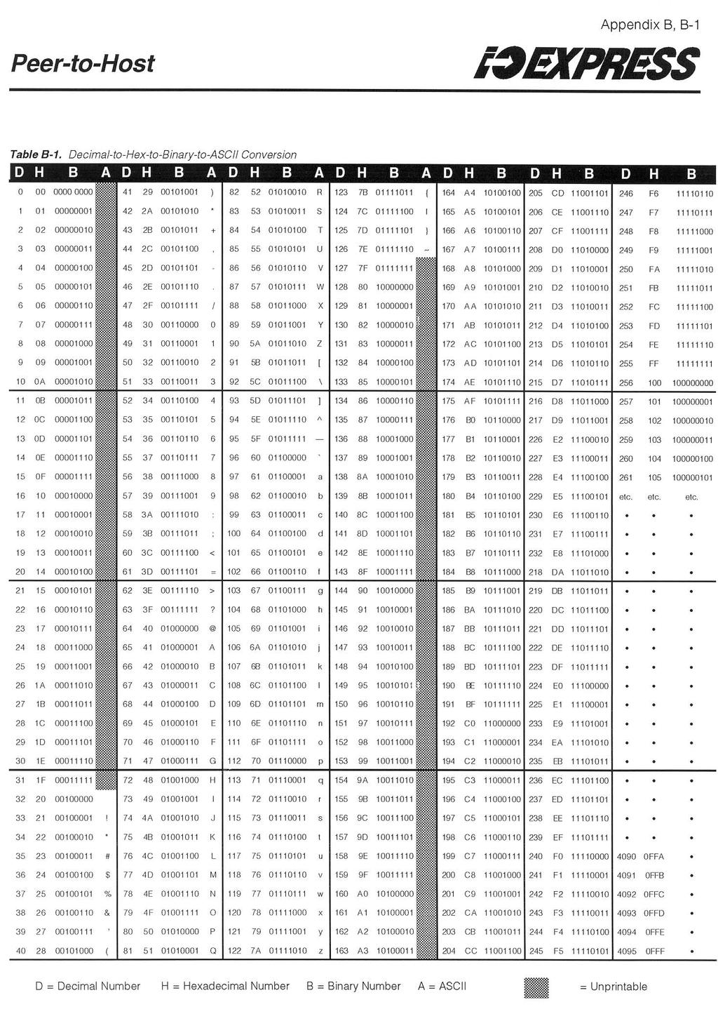
24 Page 21 Accessing Slave Module Data As it comes in to the Master, data from each Slave is automatically routed to internal areas, or bins in the memory of the Master. Bins are further broken down (in memory) into byte addresses according to channel and the type of signal represented, analog or digital. ands to change the state or level of Slave module output channels are processed in the same way, starting with the Host, proceeding through the Master to the Slave addressed by the data byte or bytes in the query. Table 4 lists the byte addresses of Slave module data in a Master. In the table, column A lists the Slave numbers (the input channel on the Master), column B lists the I/ O channels on the Slave module, column C lists the addresses for discrete (digital) data, and column D lists the addresses for analog data. To access or effect the I/ O connected to a Slave, a MODBUS query that includes the data byte address must first be communicated to the Master module, where it is decoded and sent to the appropriate Slave. Temperature and Analog I/O Data Data for thermocouple, RTD, and Analog input modules may be accessed by MODBUS function codes 03 or 04. The data is in 16-bit signed integer format. Thermocouple and RTD data is based on temperature: with 0 C input the host reads 0000; the RTD module gives 10 binary counts per C and thermocouple modules give 2 counts per C. For the 4-20mA input or output modules, the host reads (or writes) 0000 to 4095 for the 4-20mA range. Data goes negative below 4mA and is linear to 3.4mA. For the voltage input modules, data goes from 0000 to 4095 for the 0 to 100% signal range unications Status LEDs and Alarms There are 8 LEDs in the area of each unit s top panel labeled Status and Alarms. These indicate the status of both the unit s communications to and from the other modules connected on the. Each unit also has 4, open collector transistor outputs tied to the LEDs at terminals 5, 6, 7, and 8. The transistors are common negative at the C terminal of Configure Address and Baud Rate. These can be used with simple discrete devices to warn of communications faults. Table 5 summarizes the way the LEDs and outputs work. NOTE: Terminals 1 through 6 DO NOT necessarily indicate that either link is good or bad. If they are not pulsing, it may simply mean that there is no communications activity on that particular. Fault Flags There are twelve fault flags, located at memory addresses 256 through 267 in Master module memory, used to return data on the status of a Master module s Slave channels. Use the 02 MODBUS RTU function code, Read Discrete Inputs (Read Input Status), to find out whether a particular Slave module is on- or off-line. The 02 code, addressed to the Fault Flag area of memory, returns a 16-bit integer. A binary 0 indicates a good Master-to-Slave link, a 1 indicates that the module at that address is off-line. Disregard the last four (least significant, right-most) bits in the response. Complete Systems Moore Industries configures complete, turn-key systems using the I/O EXPRESS and our proven line of premium signal conditioners and transmitters. For more information, or for information on how to use the I/O EXPRESS in a Peer-to-Peer application, obtain a copy of the Peer-to-Peer Users Manual from your Moore Industries Sales Representative, or contact the factory.
25 Page 22 Table 4. I/O EXPRESS Master Module Slave Data Byte Addressing A B C D A B C D A B C D A B C D A B C D A B C D A = SLAVE MODULE B = SLAVE MODULE C = DISCRETE (DIGITAL) DATA ADDRESS D = ANALOG DATA ADDRESS
26 Page 23 Table 5. I/O EXPRESS Status and Alarm Outputs Terminals/LEDs Indication & 8 activity on #1 OFF OFF DO NOT USE DO NOT USE PULSING OFF 7 is OFF 8 is PULSING activity on #2 OFF OFF DO NOT USE DO NOT USE OFF PULSING 7 is OFF 8 is PULSING No Activity OFF OFF DO NOT USE DO NOT USE OFF OFF 7 is ON 8 is OFF Customer Support Moore Industries is recognized as the industry leader in delivering top quality to its customers, both in products and services. We perform a battery of stringent quality assurance checks on every unit we ship. If any Moore Industries product fails to perform up to rated specifications, call us for help. Our highly skilled staff of trained technicians and engineers pride themselves on their ability to provide timely, accurate, and practical answers to your process instrumentation questions. Factory phone numbers are on the back cover. If problems involve a particular DDS module, there are several pieces of information you can gather before you call the factory that will help our staff to get you answers more efficiently. When you call, please have: The model number of the unit in question. The serial number of the unit in question. The job number (if available) The purchase order under which the unit was shipped (if available)
27
28
29
30
31
32
33
34
35 Installation RETURN PROCEDURES To return equipment to Moore Industries for repair, follow these four steps: 1. Call Moore Industries and request a Returned Material Authorization (RMA) number. Warranty Repair If you are unsure if your unit is still under warranty, we can use the unit s serial number to verify the warranty status for you over the phone. Be sure to include the RMA number on all documentation. Non-Warranty Repair If your unit is out of warranty, be prepared to give us a Purchase Order number when you call. In most cases, we will be able to quote you the repair costs at that time. The repair price you are quoted will be a Not To Exceed price, which means that the actual repair costs may be less than the quote. Be sure to include the RMA number on all documentation. 2. Provide us with the following documentation: a) A note listing the symptoms that indicate the unit needs repair b) Complete shipping information for return of the equipment after repair c) The name and phone number of the person to contact if questions arise at the factory 3. Use sufficient packing material and carefully pack the equipment in a sturdy shipping container. 4. Ship the equipment to the Moore Industries location nearest you. The returned equipment will be inspected and tested at the factory. A Moore Industries representative will contact the person designated on your documentation if more information is needed. The repaired equipment, or its replacement, will be returned to you in accordance with the shipping instructions furnished in your documentation. WARRANTY DISCLAIMER THE COMPANY MAKES NO EXPRESS, IMPLIED OR STATUTORY WARRAN- TIES (INCLUDING ANY WARRANTY OF MERCHANTABILITY OR OF FITNESS FOR A PARTICULAR PURPOSE) WITH RESPECT TO ANY GOODS OR SER- VICES SOLD BY THE COMPANY. THE COMPANY DISCLAIMS ALL WARRAN- TIES ARISING FROM ANY COURSE OF DEALING OR TRADE USAGE, AND ANY BUYER OF GOODS OR SERVICES FROM THE COMPANY ACKNOWL- EDGES THAT THERE ARE NO WARRANTIES IMPLIED BY CUSTOM OR US- AGE IN THE TRADE OF THE BUYER AND OF THE COMPANY, AND THAT ANY PRIOR DEALINGS OF THE BUYER WITH THE COMPANY DO NOT IMPLY THAT THE COMPANY WARRANTS THE GOODS OR SERVICES IN ANY WAY. ANY BUYER OF GOODS OR SERVICES FROM THE COMPANY AGREES WITH THE COMPANY THAT THE SOLE AND EXCLUSIVE REMEDIES FOR BREACH OF ANY WARRANTY CONCERNING THE GOODS OR SERVICES SHALL BE FOR THE COMPANY, AT ITS OPTION, TO REPAIR OR REPLACE THE GOODS OR SERVICES OR REFUND THE PURCHASE PRICE. THE COMPANY SHALL IN NO EVENT BE LIABLE FOR ANY CONSEQUENTIAL OR INCIDENTAL DAMAGES EVEN IF THE COMPANY FAILS IN ANY ATTEMPT TO REMEDY DEFECTS IN THE GOODS OR SERVICES, BUT IN SUCH CASE THE BUYER SHALL BE ENTITLED TO NO MORE THAN A REFUND OF ALL MONIES PAID TO THE COMPANY BY THE BUYER FOR PURCHASE OF THE GOODS OR SERVICES. ANY CAUSE OF ACTION FOR BREACH OF ANY WARRANTY BY THE COMPANY SHALL BE BARRED UNLESS THE COMPANY RECEIVES FROM THE BUYER A WRITTEN NOTICE OF THE ALLEGED DEFECT OR BREACH WITHIN TEN DAYS FROM THE EARLIEST DATE ON WHICH THE BUYER COULD REASONABLY HAVE DISCOVERED THE ALLEGED DE- FECT OR BREACH, AND NO ACTION FOR THE BREACH OF ANY WAR- RANTY SHALL BE COMMENCED BY THE BUYER ANY LATER THAN TWELVE MONTHS FROM THE EARLIEST DATE ON WHICH THE BUYER COULD REASONABLY HAVE DISCOVERED THE ALLEGED DEFECT OR BREACH. RETURN POLICY For a period of thirty-six (36) months from the date of shipment, and under normal conditions of use and service, Moore Industries ("The Company") will at its option replace, repair or refund the purchase price for any of its manufactured products found, upon return to the Company (transportation charges prepaid and otherwise in accordance with the return procedures established by The Company), to be defective in material or workmanship. This policy extends to the original Buyer only and not to Buyer's customers or the users of Buyer's products, unless Buyer is an engineering contractor in which case the policy shall extend to Buyer's immediate customer only. This policy shall not apply if the product has been subject to alteration, misuse, accident, neglect or improper application, installation, or operation. THE COMPANY SHALL IN NO EVENT BE LIABLE FOR ANY INCIDENTAL OR CONSE- QUENTIAL DAMAGES Moore Industries-International, Inc. 500 Series Specifications and information subject Installation to change Guide without notice.
500 SERIES. Hardware Installation and Modification Manual. Process Controllers. for Electronic Products Series 531, 532, 535, 545, 555 Model 2
 500 SERIES Process Controllers Installation Form M500 V7 5 0 0 Hardware Installation and Modification Manual for Electronic Products Series 531, 532, 535, 545, 555 Model 2 Installation Guide 500 Series
CPT CPT HLPRG. PC-Programmable Signal. Isolater/Converter. PC-Programmable Signal Isolater/Converter. January B
 January 2004 225-708-00 B CPT HLPRG CPT All product names are registered trademarks of their respective companies. Table of Contents Introduction...4 About this Manual... 4 The CPT...4 Model and Serial
PWH USER S MANUAL. Watt/Watt-hour Transducer. January No B by Moore Industries-International, Inc.
 January 1992 Watt/Watt-hour Transducer USER S MANUAL No. 317-701-00 B 1992 by Moore Industries-International, Inc. Table of Contents Introduction 1 Description 1 Calibration 5 Installation 16 Operation
FCT. Field-Configurable Signal Converter/Isolator. June C. Signal Converter/Isolator. Field-Configurable FCT
 June 1996 146-711-00 C Field-Configurable Signal Converter/Isolator Field-Configurable Signal Converter/Isolator Table of Contents Introduction 1 Description 1 Specifications 2 Ordering Information 2 Calibration
Tempco Instruction Manual
 Tempco Instruction Manual 1/16 DIN Solid State Temperature Controller Relay Output Solid State Output For Heating Model Numbers: TEC-901, TEC-902, TEC-905 Temperature controls in this series are designed
MIX MIX. Signal Isolator/Convertor. 2 -Wire, 2-Channel. May B. 2-Wire, 2-Channel. Signal Isolator/Convertor
 May 2016 20677500B 2Wire, 2Channel MIX MIX 2 Wire, 2Channel Table of Contents Introduction... 3 About this Manual... 3 Model and Serial Numbers... 3 Inputs and Ouputs... 3 Specifications... 4 Dimensions...
EASON TECHNOLOGY. IO8 & IO24 Break-Out Module
 EASON TECHNOLOGY IO8 & IO24 Break-Out Module p/n 50-00180-01 Revision1.2 Eason Technology, Inc. 7975 Cameron Dr. Bldg 300 Windsor, CA 95492 Phone (707) 837-0120 FAX (707) 837-2742 http://www.eason.com
USER S MANUAL No B
 April 2016 Phase Angle Transducer USER S MANUAL No. 311-701-00 B 1992 by Moore Industries-International, Inc. Table of Contents Introduction 1 Description 1 Calibration 4 Installation 12 Operation 13 Maintenance
CTI 2551-A 8-CHANNEL ISOLATED THERMOCOUPLE INPUT MODULE INSTALLATION AND OPERATION GUIDE. Version 1.3 CTI Part # * *
 CTI 2551-A 8-CHANNEL ISOLATED THERMOCOUPLE INPUT MODULE INSTALLATION AND OPERATION GUIDE Version 1.3 CTI Part #062-00305-013 *062-00305-011* 2551-AIOG 110106 $25 Copyright 2006 Control Technology Inc.
Industrial Ethernet Ethernet to Serial Gateways Ethernet to Serial Converters for Modbus, Red lion and other protocols
 USER MANUAL Industrial Ethernet Ethernet to Serial Gateways Ethernet to Serial Converters for Modbus, Red lion and other protocols Contents at a Glance: Section 1 General Information RM-PS-024-01F 3 Section
NCS MIM. with MODBUS Interface. NET Concentrator System. September A. with MODBUS Interface
 September 2003 288-766-00 A NCS MIM with MODBUS Interface NCS MIM with MODBUS Interface Table of Contents The...3 About this Manual...3 The MODBUS Interface (MIM)... 4 Specifications MIM...5 Connecting
FTC-200 X-ray Tube Controller Users Manual
 Tubes FTC-200 X-ray Tube Controller TUB-MAN-2101 Rev. A 09/09/2009TTUB Table of Contents List of Tables...3 List of Figures...3 Introduction...3 Manual Set...3 About this Manual...4 X-Ray Safety Information...4
Contents. HP E1586A Rack Mount Terminal Panel User s Manual
 Contents HP E1586A Rack Mount Terminal Panel User s Manual Description... 5 Connecting to VXIbus Instruments... 5 Interconnect Cables... 5 Terminal Block Connections... 6 Using the Terminal Panel for Reference
D7000 SERIES MODBUS TCP/IP ETHERNET INTERFACE MODULES
 11/17 D7000 SERIES MODBUS TCP/IP ETHERNET INTERFACE MODULES D7000 FEATURES Complete data acquisition systems. Analog and Digital I/O models available. RJ-45 Ethernet 10/100MB interface. Modbus TCP/IP Ethernet
POWER SERIES Plus Watt / VAR / Power Factor Digital Switchboard Meter User s Manual IM2493WVP-3
 POWER SERIES Plus Watt / VAR / Power Factor Digital Switchboard Meter User s Manual General Description The POWER SERIES Plus digital switchboard meters incorporate the latest DSP microprocessor technology.
LCI Load Cell Junction Box with Fault Monitor
 LCI Load Cell Junction Box with Fault Monitor User Manual www.mantracourt.co.uk The LCI Load Cell Failure Alarm Manual Chapter 1 Introduction to the LCI...2 Chapter 2 Installing the LCI...3 Figure 2.1
D1000M SERIES FOR MODBUS SENSOR TO COMPUTER INTERFACE MODULES
 D1000M SERIES FOR MODBUS SENSOR TO COMPUTER INTERFACE MODULES D1000 FEATURES Complete sensor to RS-232/RS-485 interface. 500V rms analog input isolation. 15 bit measurement resolution. Continuous self-calibration;
CTI 3570A SERIES INDUSTRIAL ETHERNET SWITCH INSTALLATION AND OPERATION GUIDE Version 1.2
 CTI 3570A SERIES INDUSTRIAL ETHERNET SWITCH INSTALLATION AND OPERATION GUIDE Version 1.2 CTI Part # 062-00355-012 3570AIOG 033104 $25 i Copyright 2004 Control Technology Inc. All rights reserved. This
MD9 MULTIDROP INTERFACE INSTRUCTION MANUAL
 MD9 MULTIDROP INTERFACE INSTRUCTION MANUAL REVISION: 01/05/03 COPYRIGHT (c) 1987-2003 CAMPBELL SCIENTIFIC, INC. This is a blank page. WARRANTY AND ASSISTANCE The MD9 MULTIDROP INTERFACE is warranted by
Power Supply Input voltage 20.4VDC to 28.8VDC with less than 10% ripple Max. current consumption See Note 1
 Vision OPLC V350-35-TRA22 Technical Specifications The Unitronics V350-35-TRA22 offers the following onboard I/Os: 12 Digital Inputs, configurable via wiring to include 2 Analog, 2 PT100/TC and 1 HSC/Shaftencoder
DICKSON FH320/325 & FT300/325 DICKSON. Temperature/Humidity Recorder. Specifications. Applications & Product. Product. Contents: Getting Started
 FH320/325 & FT300/325 Temperature/Humidity Recorder Contents: and Instrument Anatomy Accessories Warranty / Accessories, & Calibration FH325 Remote Probe Temperature & Humidity FT325 Remote Probe 2 Channel
TC1880 Series. 4/5/6/8 Channel RS-232 FIBER OPTIC MICRO MUX User's Manual
 Series 4/5/6/8 Channel RS-232 FIBER OPTIC MICRO MUX MODEL: S/N: DATE: Notice! Although every effort has been made to insure that this manual is current and accurate as of date of publication, no guarantee
M82xxD Fiber Optic RS-232 MicroModem Technical Manual
 M82xxD Fiber Optic RS-232 MicroModem Technical Manual Revision C August 2016 VERSITRON, Inc. 83 Albe Drive / Suite C Newark, DE 19702 www.versitron.com Safeguarding Communications Since 1958 PROPRIETARY
OP8/16 Optoisolated Digital Input Board User's Manual
 OP8/16 Optoisolated Digital Input Board User's Manual Real Time Devices USA, Inc. Accessing the Analog World Publication No. OP16-9742 OP8/16 User's Manual REAL TIME DEVICES USA 820 North University Drive
POWER SERIES Plus. 3 in 1 AC Voltage. Digital Switchboard Meter. User s Manual IM2493VVV-2
 POWER SERIES Plus 3 in 1 AC Voltage Digital Switchboard Meter User s Manual General Description The POWER SERIES Plus digital switchboard meters incorporate the latest DSP microprocessor technology. Careful
LPG STM 94442A User s Manual
 1 LPG STM 94442A User s Manual This Manual belongs to: Company: 3 Table of Contents Features....... 4 Hardware Installation...5 Monitor Mounting Dimensions.....7 Monitor Specifications...8 Sender Specifications.....9
Omnitron Systems Technology, Inc. 1. iconverter. 19-Module Managed Power Chassis User s Manual
 Omnitron Systems Technology, Inc. 1 iconverter 19-Module Managed Power Chassis User s Manual 27 Mauchly, #201, Irvine, CA 92618 Phone: (949) 250-6510; Fax: (949) 250-6514 2 Omnitron Systems Technology,
RS-485 Fiber-Optic Link RS-485 to Multi-Mode Fiber-Optic converter ST Fiber Connectors DIN Rail Mount
 Fiber-Optic Link to Multi-Mode Fiber-Optic converter ST Fiber Connectors DIN Rail Mount 101-0079 Installation Operation & Specifications Manual Auto-direcon control Supports BAUD rates up to 115,200 Fiber
Installation & Operation
 LED Readout Installation & Operation WARRANTY Accurate Technology, Inc. warrants the ProScale Systems against defective parts and workmanship for 1 year commencing from the date of original purchase. Upon
GASGUARDIAN RD3 Remote Display OPERATING & INSTALLATION MANUAL
 GASGUARDIAN RD3 OPERATING & INSTALLATION MANUAL 3GasGuardian RD Operating and Instruction Manual Table of Contents General description... 4 Installation... 4 Locating the GasGuardian RD1... 4 Installation
F271XA Fiber-Optic Telephone Modem Technical Manual
 F271XA Fiber-Optic Telephone Modem Technical Manual Revision B August 2011 VERSITRON, Inc. 83 Albe Drive / Suite C Newark, DE 19702 www.versitron.com Safeguarding Communications Since 1958 PROPRIETARY
1/32-DIN TEMPERATURE CONTROLLER INSTALLATION, WIRING AND OPERATION MANUAL FORM 3882
 1/32-DIN TEMPERATURE CONTROLLER INSTALLATION, WIRING AND OPERATION MANUAL FORM 3882 This manual is intended for use in support of installation, commissioning and configuration of the 1/32-DIN Temperature
User's Guide. Extech AM A AC Analog Clamp Meter
 User's Guide Extech AM300 300A AC Analog Clamp Meter Introduction Congratulations on your purchase of the Extech AM300 Analog Clamp Meter. This device measure AC Voltage and Current, DC Voltage, and Resistance.
LCI User Manual mantracourt.com
 LCI User Manual mantracourt.com LCI Load Cell Junction Box with Fault Monitor Contents Chapter 1 Introduction to the LCI... 2 Chapter 2 Installing the LCI... 3 Chapter 3 Setting up the LCI... 4 Sequence
POWER SERIES Plus Watt-VAR / Watt-Power Factor Digital Switchboard Meter User s Manual IM2492WVPF-1
 POWER SERIES Plus Watt-VAR / Watt-Power Factor Digital Switchboard Meter User s Manual General Description The POWER SERIES Plus digital switchboard meters incorporate the latest DSP microprocessor technology.
20.4VDC to 28.8VDC with less than 10% ripple. Input impedance 10mSec typical, when used as normal digital inputs
 Vision OPLC V130-33-RA22 Technical Specifications This guide provides specifications for Unitronics model V130-33-RA22. General features include: 12 pnp/npn Digital, including 2 Analog, 2 PT100/TC, 1 HSC/Shaft-encoder
MTS-2000 USER S MANUAL
 MTS-2000 USER S MANUAL USER s MANUAL - March 2010 MTS-2000 METER TEST SYSTEM Pay special attention to the warnings and safety instructions that accompany the above symbol wherever it is found within this
F271XAD Fiber-Optic Telephone Modem with RS485 Data Technical Manual
 F271XAD Fiber-Optic Telephone Modem with RS485 Data Technical Manual Revision A January 2014 VERSITRON, Inc. 83 Albe Drive / Suite C Newark, DE 19702 www.versitron.com Safeguarding Communications Since
PIECAL 322 Automated Thermocouple Calibrator Operating Instructions. Product Description. Practical Instrument Electronics
 PIECAL 322 Automated Thermocouple Calibrator Operating Instructions Product Description Easy to use With the PIECAL 322-1 you can check & calibrate all your thermocouple instruments and measure thermocouple
3 Digital, 3 Digital/Analog, 3 PT1000/NI1000 Inputs, 5 Relay, 1 pnp/npn Outputs
 JZ10-11-PT15 3 Digital, 3 Digital/Analog, 3 PT1000/NI1000 Inputs, 5 Relay, 1 pnp/npn Outputs Jazz Micro-OPLCTechnical Specifications Power supply Input voltage Permissible range 20.4VDC to 28.8VDC with
AnalogBridge Analog transmission system
 AnalogBridge Analog transmission system Enclosure showing RTU Module and optional Power supply, External Relay User Guide Revision 1.4 Wireless Solutions at Work www.orbitcoms.com Page 1 Orbit Communications
ES-600 Ozone Controller Operation Manual
 ES-600 Ozone Controller Operation Manual Questions about your product? Find answers here: Web: www.ozonesolutions.com/es-600 Phone: 712-439-6880 Ozone Solutions OZONE CONTROLLER Model ES-600 Instructions
Model 206 Operating Instructions. Setra Systems, Inc. 159 Swanson Road, Boxborough, MA
 Model 206 Operating Instructions Setra Systems, Inc. 159 Swanson Road, Boxborough, MA 01719 800.257.3872 www.setra.com 1.0 General Information Every Model 206 has been tested and calibrated before shipment.
F280XD Fiber-Optic RS-232 Modem Technical Manual
 F280XD Fiber-Optic RS-232 Modem Technical Manual Revision B August 2012 VERSITRON, Inc. 83 Albe Drive / Suite C Newark, DE 19702 www.versitron.com Safeguarding Communications Since 1958 PROPRIETARY DATA
Secured Series: Hub Plus Kit Single Door Controller Package Installation Manual
 Secured Series: Hub Plus Kit Single Door Controller Package Installation Manual This package is designed to simplify the connections to our Secured Series Hub Plus Controller. This will translate into
INTMOD485-LH Protocol Converter
 For Use with L-GAGE LH Series Sensors Features Converts an LH Network to the 485-RTU protocol Supports baud rates up to 230,400 baud Supports LH Networks with up to 32 sensors Model Protocol Conversion
MODBUS RTU I/O Expansion Modules - Models C267, C277, and C287. Installation and Operations Manual Section 50
 MODBUS RTU I/O Expansion Modules - Models C267, C277, and C287 Installation and Operations Manual 00-02-0651 09-01-09 Section 50 In order to consistently bring you the highest quality, full featured products,
USER MANUAL CCHP-6000-XX 6kJ/s Capacitor Charging Power Supply
 26 Ward Hill Ave., Bradford, MA 01835 Phone: 978-241-8260 Fax: 978-241-8262 USER MANUAL CCHP-6000-XX 6kJ/s Capacitor Charging Power Supply 02001235 Rev 1 CCHP-6000-XX User Manual Page 1 of 14 Table of
G3NE. Model Number Structure. Solid State Relays. Model Number Legend. Compact, Low-cost, SSR Switching 5 to 20 A
 Solid State Relays CSM DS_E_4_1 Compact, Low-cost, SSR Switching 5 to 20 A Wide load voltage range: 75 to 264 VAC. Both 100-V and 200-V loads can be handled with the same model. Dedicated, compact aluminum
All Analog Outputs, voltage/current 10mA 35mA 5mA 48mA/30mA* *If the analog outputs are not configured, then subtract the higher value.
 Vision OPLC V350-35-TRA22/V350-J-TRA22 Technical Specifications The Unitronics V350-35-TRA22/V350-J-TRA22 offers the following onboard I/Os: 12 Digital Inputs, configurable via wiring to include 2 Analog,
12-36 VDC/12-24 VAC Power Option 4-Digit Display, 0.56 (14.2 mm) or 1.20 (30.5 mm)
 or 1.20 (30.5 mm)") 4-20 ma & Relay Output Features 4-20 ma, ± 10 V, TC & RTD Inputs 12-36 VDC/12-24 VAC Power Option 4-Digit Display, 0.56 (14.2 mm) or 1.20 (30.5 mm) 24 VDC @ 200 ma Transmitter Power Supply Options Type
4-20 ma & Relay Output Features 4-20 ma, ± 10 V, TC & RTD Inputs 12-36 VDC/12-24 VAC Power Option 4-Digit Display, 0.56 (14.2 mm) or 1.20 (30.5 mm) 24 VDC @ 200 ma Transmitter Power Supply Options Type
USER MANUAL. MODELS 1205 and 1205/34. Synchronous V.35 Modem Eliminators
 USER MANUAL MODELS 1205 and 1205/34 Synchronous V.35 Modem Eliminators An ISO-9001 Certified Company Part #07M1205-D Doc #049021U, Rev. E Revised 1/22/08 SALES OFFICE (301) 975-1000 TECHNICAL SUPPORT (301)
RSTC1000 HMI/PLC Design Guide WEB CONTROL PRODUCTS. User Manual FORM NO. L B MTY (81)
") WEB CONTROL PRODUCTS User Manual RSTC1000 HMI/PLC Design Guide DANGER Read this manual carefully before installation and operation. Follow Nexen s instructions and integrate this unit into your system
WEB CONTROL PRODUCTS User Manual RSTC1000 HMI/PLC Design Guide DANGER Read this manual carefully before installation and operation. Follow Nexen s instructions and integrate this unit into your system
ECT Signal Isolator/Converter
 August 1997 Now with Dual I/O Channels Data Sheet 2.02 Description The family of signal isolators and converters delivers economical solutions for a wide variety of signal interface applications. Isolator
500 Business Center Drive Pittsburgh, PA USA CAGE 1BGJ7. SwitchMaster R5000 Series Ultra-Compact Ganged A/B Switching System
 Market Central www.secureswitch.com 500 Business Center Drive Pittsburgh, PA 15205 USA 412.494.2800 CAGE 1BGJ7 SwitchMaster R5000 Series Ultra-Compact Ganged A/B Switching System July, 2014 COMPLETE 2
SX90 Process Controller
 Local regulations may restrict the use of this product to below the conditions quoted. In the interests of development and improvement of the product, we reserve the right to change the specification without
S82S (3/7.5-W Models)
") Switch Mode Power Supply (3/7.5-W Models) CSM DS_E_4_3 Miniature DIN Rail Mounting DC-DC Power Supplies 65 mm depth enables mounting onto control panels with 100 mm depth. Inputs: 10.2 to 27.6 VDC (DC
Switch Mode Power Supply (3/7.5-W Models) CSM DS_E_4_3 Miniature DIN Rail Mounting DC-DC Power Supplies 65 mm depth enables mounting onto control panels with 100 mm depth. Inputs: 10.2 to 27.6 VDC (DC
EIDX_M Series INSTALLATION GUIDE INTRODUCTION. A Line of Managed Ethernet Switching Hubs
 EIDX_M Series A Line of Managed Ethernet Switching Hubs INTRODUCTION INSTALLATION GUIDE The EIDX_M Series of managed Industrial Ethernet switches provides the user with a sophisticated instrument with
Eco Sensors OZONE CONTROLLER Model OS-6 Instructions for Use. General and New Features
 Eco Sensors OZONE CONTROLLER Model OS-6 Instructions for Use General and New Features The OS-6 is an industrial grade Ozone controller and monitor. The OS-6 design has been optimized for accuracy, ease
SVP110 SURGE VOLTAGE PROTECTOR INSTRUCTION MANUAL
 SVP110 SURGE VOLTAGE PROTECTOR INSTRUCTION MANUAL REVISION: 01/03/03 COPYRIGHT (c) 1995-2000 CAMPBELL SCIENTIFIC, INC. This is a blank page. WARRANTY AND ASSISTANCE The SVP110 SURGE VOLTAGE PROTECTOR is
Intech Micro 2300-RTD6 analogue input station MODBUS RTU slave application supplementary manual.
 Intech Micro 2300-RTD6 analogue input station MODBUS RTU slave application supplementary manual. MODBUS supplementary manual to the 2300-RTD6 Installation Guide. The 2300 series stations are designed to
AE14-503J SERIES PRODUCTION DISPLAY SYSTEM
 FN:503JMAN2.DOC AE14-503J SERIES PRODUCTION DISPLAY SYSTEM DESCRIPTION The AE14-503J Series Production Display System is a stand-alone production pacing (Goal) and monitoring (Actual) display. It includes
Power Meter PowerMonitor 500
 ROCKWELL AUTOMATION PROCUREMENT SPECIFICATION PROCUREMENT SPECIFICATION PowerMonitor 500 NOTICE: The specification guidelines in this document are intended to aid in the specification of products. Specific
MODBUS MANUAL For the AccUView UV Transmission Monitor
 MODBUS MANUAL For the AccUView UV Transmission Monitor HF scientific, inc. 3170 Metro Parkway Ft. Myers, FL 33916 Phone: 239-337-2116 Fax: 239-332-7643 E-Mail: info@hfscientific.com Website: www.hfscientific.com
R1M-GH THERMOCOUPLE & DC INPUT MODULE MODEL. Remote I/O R1M Series. (16 points)
") Remote I/O R1M Series THERMOCOUPLE & DC INPUT MODULE (16 points) MODEL MODEL & SUFFIX CODE SELECTION R1MGH2T MODEL Modbus protocol I/O TYPE GH2 : Thermocouple or DC input, 16 points FIELD TERMINAL TYPE
Remote I/O R1M Series THERMOCOUPLE & DC INPUT MODULE (16 points) MODEL MODEL & SUFFIX CODE SELECTION R1MGH2T MODEL Modbus protocol I/O TYPE GH2 : Thermocouple or DC input, 16 points FIELD TERMINAL TYPE
CTI 2550 EIGHT CHANNEL ISOLATED ANALOG INPUT MODULE INSTALLATION AND OPERATION GUIDE. Version 2.0 CTI Part # IOG $25
 CTI 2550 EIGHT CHANNEL ISOLATED ANALOG INPUT MODULE INSTALLATION AND OPERATION GUIDE Version 2.0 CTI Part #062-00102 2452IOG 092205 $25 ii CTI 2550 Installation and Operation Guide Copyright 2005 Control
Section 1 Introduction
 Section 1 Introduction The AT90ICEPRO is a real time In-Circuit Emulator (ICE) for all AT90S1200, -S2313, -S2323, -S2333, -S2343, -S4414, -S4433, -S4434, -S8515 and -S8535 devices. It can be upgraded to
I/O SIGNAL CONDITIONER
 Technical Data Sheet No. TD9809M Rev. F Date of Issue: December 9, 2009 OPERATING MANUAL I/O SIGNAL CONDITIONER CAUTION: THIS PRODUCT DOES NOT PROVIDE GALVANIC ISOLATION. DO NOT ATTEMPT USE OF THIS PRODUCT
All Analog Outputs, voltage/current 20mA 35mA 5mA 48mA/30mA* *If the analog outputs are not configured, then subtract the higher value.
 Vision OPLC V350-35-TA24/V350-J-TA24 Technical Specifications The Unitronics V350-35-TA24/V350-J-TA24 offers the following onboard I/Os: 12 Digital Inputs, configurable via wiring to include 2 Analog,
Samba PLC+HMI SM35-J-RA22
 Samba PLC+HMI SM35-J-RA22 SM43-J-RA22 Technical Specifications Ordering Information Item SM35-J-RA22 PLC with Flat panel, Color touch display 3.5 SM43-J-RA22 PLC with Flat panel, Color touch display 4.3
ABB Drives. User s Manual. Modbus Adapter Module RMBA-01
 ABB Drives User s Manual Modbus Adapter Module RMBA-01 Modbus Adapter Module RMBA-01 User s Manual 3AFE 64498851 REV A EN EFFECTIVE: 1.3.2002 2002 ABB Oy. All Rights Reserved. Safety instructions Overview
MYRIAD QLC 4-CHANNEL MONITOR/CONTROLLER INSTRUCTION MANUAL
 MYRIAD QLC 4-CHANNEL MONITOR/CONTROLLER INSTRUCTION MANUAL VISIT OUR WEBSITE SIGMACONTROLS.COM MYR QLC MANUAL 013114 2 TABLE OF CONTENTS INTRODUCTION 3 Ordering Information Specifications Features WIRING
RemoteTRAK RS485 Distributed I/O for Modbus and Sixnet Systems
 RemoteTRAK RS485 Distributed I/O for Modbus and Sixnet Systems USER MANUAL Installation & Maintenance Contents at a Glance: Section 1 General Information RM-PS-024-01F 3 Section 2 RS485 Wiring RM-232-485-4U
C160 Wall-/Pipe Mounted Universal Process Indicator
 Data sheet DS/ EN Rev. I Wall-/Pipe Mounted Universal Process Indicator reliable process indicator, wherever it s needed High visibility LED display the clearest view of your process status 0.1% measurement
EOTec MX Multiplexer System
 Nuclear Sensors & Process Instrumentation EOTec MX Multiplexer System Bi-Directional Control & Communications User Manual Original Instructions 2 EOTec MX Multiplexer System User Manual Nuclear Sensors
ADAM-5511 Quick Start
 ADAM-5511 Quick Start Support Firmware 1.01 or above Copyright Notice This document is copyrighted 2001 by Advantech Co., Ltd. All rights are reserved. Advantech Co., Ltd., reserves the right to make improvements
Trident and Trident X2 Digital Process and Temperature Panel Meter
 Sign In New User ISO 9001:2008 Certified Quality System Home Products Online Tools Videos Downloads About Us Store Contact Policies Trident and Trident X2 Digital Process and Temperature Panel Meter Products
E2K-F. Flat Capacitive Sensor with a Thickness of Only 10 mm. Flat Proximity Sensor. Ordering Information. Sensors [Refer to Dimensions on page 4.
 Flat Proximity Sensor EK-F CSM_EK-F_DS_E Flat Capacitive Sensor with a Thickness of Only mm Flat Sensor with excellent space efficiency. (Model with built-in Amplifier is only mm thick.) Direct mounting
Installation, Operation & Maintenance Instructions / Technical Document
 Installation, Operation & Maintenance Instructions / Technical Document Model VHL Mini Vibrating Fork Point Level Sensor for Liquids Thank you for purchasing the Model VHL Mini Vibrating Fork Point Level
INSTALLATION, OPERATION & MAINTENANCE CRFF Series Wall Control Console. ECM Motors. ACC1-25 (Part # ) Revision:
 Revision:") INSTALLATION, OPERATION & MAINTENANCE CRFF Series Wall Control Console ACC1-25 (Part # 63971-002) ECM Motors Revision: 10.01.13 Page: 2 of 11 Table of Contents Safety Precautions...3 Overview...3 Specifications...4
INSTALLATION, OPERATION & MAINTENANCE CRFF Series Wall Control Console ACC1-25 (Part # 63971-002) ECM Motors Revision: 10.01.13 Page: 2 of 11 Table of Contents Safety Precautions...3 Overview...3 Specifications...4
OPERATING MANUAL LOW-VOLTAGE DISCONNECT PANELS LVD400 & LVD600 SERIES
 PRICE: $25.00 LOW-VOLTAGE DISCONNECT PANELS LVD400 & LVD600 SERIES www.unipowertelecom.com Manual No. LVD-201-2 8/29/01/L46Man 2001 UNIPOWER Corp. All Rights Reserved UNIPOWER Telecom, Division of UNIPOWER
Eco Sensors OZONE CONTROLLER Model OS-6 Instructions for Use. General and New Features
 Eco Sensors OZONE CONTROLLER Model OS-6 Instructions for Use General and New Features The OS-6 is an industrial grade Ozone controller and monitor. The OS-6 design has been optimized for accuracy, ease
Analog Interface Unit Operation Manual
 Analog Interface Analog Interface Unit Operation Manual WARRANTY Accurate Technology, Inc. warrants the product against defective parts and workmanship for 1 year commencing from the date of original purchase.
XC4100 INSTALLATION/OWNER'S MANUAL AM/FM/Cassette Receiver
 XC4100 INSTALLATION/OWNER'S MANUAL AM/FM/Cassette Receiver Preparation XC4100 INSTALLATION Please read entire manual before installation. Before You Start Disconnect negative battery terminal. Consult
INSTRUCTION and OPERATIONS MANUAL. for
 INSTRUCTION and OPERATIONS MANUAL for CAB SIGNAL MASTER MODEL NUMBER 15100-00 CAUTION Be sure to read and become thoroughly familiar with the entire contents of this manual before attempting to operate
Model SC500. Programmable Single-Channel Transducer Indicator/Conditioner DESCRIPTION FEATURES
 Programmable Single-Channel Transducer Indicator/Conditioner DESCRIPTION The SC series models are self-calibrating microprocessorbased transducer signal conditioners when used with sig mod equipped transducers.
4300 WINDFERN RD #100 - HOUSTON TX VOICE (713) FAX (713) web: IMPORTANT!!!
 FAX (713) web: IMPORTANT!!!") 4300 WINDFERN RD #100 - HOUSTON TX 77041-8943 VOICE (713) 973-6905 - FAX (713) 973-9352 web: www.twrlighting.com IMPORTANT!!! PLEASE TAKE THE TIME TO FILL OUT THIS FORM COMPLETELY. FILE IT IN A SAFE PLACE.
4300 WINDFERN RD #100 - HOUSTON TX 77041-8943 VOICE (713) 973-6905 - FAX (713) 973-9352 web: www.twrlighting.com IMPORTANT!!! PLEASE TAKE THE TIME TO FILL OUT THIS FORM COMPLETELY. FILE IT IN A SAFE PLACE.
BACnet Router Start-up Guide
 BACnet Router Start-up Guide BAS Router (BACnet Multi-Network Router) APPLICABILITY & EFFECTIVITY Effective for all systems manufactured after October 2014 Kernel Version: 6.15 Document Revision: 3 QuickServer
MR52 READER INTERFACE
 IN IN2 IN3 IN4 INPUTS IN5 IN6 IN7 IN8 C www.mercury-security.com 2355 MIRA MAR AVE. LONG BEACH, CA 9085-755, (562)986-905 FAX (562) 986-9205 MR52 READER INTERFACE Installation and Specifications: This
The Next-generation Sensor Networking Units That Revolutionize the Workplace from Introduction and Startup though Operation. Fiber Units.
 Sensor Communications Unit CSM DS_E_1_1 The Next-generation Sensor Networking Units That Revolutionize the Workplace from Introduction and Startup though Operation Low initial cost achieved by distributed
XBDM. 1015LV, 1020LV, 1030LV, 1020HV Models USER & INSTALLATION MANUAL BYPASS DISTRIBUTION MODULE
 XBDM 1015LV, 1020LV, 1030LV, 1020HV Models USER & INSTALLATION MANUAL www.xpcc.com 2013 Xtreme Power Conversion Corporation. All rights reserved. Table of Contents IMPORTANT SAFETY INSTRUCTIONS:... 4 INTRODUCTION...
ME15 Magnetic Encoder Manual Revision 1.1
 Product Overview The ME15 Magnetic Encoder is the newest addition to AMCI s Encoder product line. The encoder is designed for lower resolution and lower cost applications and provides 10 bits of resolution.
TRENDnet User s Guide. Cover Page
 Cover Page Table of Contents Contents Product Overview... 2 Package Contents... 2 Features... 2 Product Hardware Features... 3 Application Diagram... 4 Installation - Hardware... 4 Adapter... 4 Fiber Cable...
OZONE SWITCH Model OS-6. OS-6 Features
 USER MANUAL OZONE SWITCH Model OS-6 OS-6 Features The OS-6 is an industrial grade ozone controller and monitor. The OS-6 design is optimized for accuracy and ease of installation, setup and operation.
MAXIMA + Series ROTARY LEVEL CONTROL
 Price $5.00 MAXIMA + Series ROTARY LEVEL CONTROL OPERATING INSTRUCTIONS PLEASE READ CAREFULLY Division of Garner Industries 7201 North 98th Street Lincoln, NE 68507-9741 (402) 434-9102 925-0268 TABLE OF
iconverter 2-Module Power Chassis
 iconverter 2-Module Power Chassis User Manual 38 Tesla, Irvine, CA 92618 USA Phone: (949) 250-6510; Fax: (949) 250-6514 Page 1 Warning The operating description in this Instruction Manual is for use by
Wall-/Pipe Mounted Universal Process Indicator
 Data Sheet SS/_8 Wall-/Pipe Mounted Universal Process Indicator High visibility LED display the clearest view of your process status 0.1% measurement accuracy precise indication of process measurement
G3FM. Model Number Structure. Ordering Information. Solid State Relays. Model Number Legend. List of Models
 Solid State Relays CSM DS_E_5_3 100-μA-max. Leakage Current, No Bleeder Resistor Required Reduces wiring work by 60% when combined with the PFY-08- PU Push-In Plus Socket (according to actual OMRON measurements).
CTI 2552-A 8-CHANNEL ISOLATED RTD INPUT MODULE INSTALLATION AND OPERATION GUIDE. Ver. 1.2 CTI Part #
 CTI 2552-A 8-CHANNEL ISOLATED RTD INPUT MODULE INSTALLATION AND OPERATION GUIDE Ver. 1.2 CTI Part # 062-00306-012 062-00303-011 2552-AIOG 020106 $25 Copyright 2006 Control Technology Inc. All rights reserved.
WARRANTY & LIMITATION OF LIABILITY
 MUX-2 WARRANTY & LIMITATION OF LIABILITY 1. ROTEM warrants that the product shall be free of defects in materials or workmanship and will conform to the technical specification for a period of 1 (one)