PROCESS AUTOMATION. Installation Technology for FOUNDATION Fieldbus
|
|
|
- Jacob Barton
- 6 years ago
- Views:
Transcription

1 PROCESS AUTOMATION Installation Technology for FOUNDATION Fieldbus


2 HOST Plant Communication with Fieldbus page 4 Benefit from the future proof, enabling technology page 10 Power Supply Power your field devices from a wide range of high-performance supply units page 16 Fieldbus Distribution and Segment Protection Protect your fieldbus from negative influences of short-circuits page 6 Power Feed Concepts Tailor your fieldbus topology exactly to your application Fieldbus Distribution Save on cabling with small distributors close to page 14 the field devices page 22 Fieldbus Cables and Cord Sets Support your signal transmission with high-quality cables fit for all environments. Fieldbus Process Interfaces Include your conventional field devices into the fieldbus communication page 20 2

3 Connecting Fieldbus Power and Knowledge page 18 Fieldbus Distribution intrinsically safe Combine the optimal explosion protection with high supply power for many field devices Fieldbus Terminators Secure your fieldbus communication page 24 Accessories, Tools and Services page 26 Surge Protection Protect your fieldbus equipment against power surges and lightning strikes page 25 Realize the benefits of modern, sophisticated instrumentation 3

4 Process Automation with Fieldbus Digital communication has almost completely penetrated the world of office communication. s are the main media of communication, the world wide web is rapidly becoming the number one information source. When looking into automated production factories, most of the control and measurement signals are communicated digitally today. Due to the specific requirements of process automation, especially in view of continuous production, plant complexity and availability as well as explosion protection, the acceptance of digital signal communication has been comparably slow. The international standard IEC Fieldbus for use in Industrial Control Systems defines a set of eight fieldbus protocols out of which the FOUNDATION Fieldbus H1 and PROFIBUS PA became rather dominant in the processing industry. These fieldbusses comply with IEC which defines the physical layer of these so-called H1 fieldbusses. The main requirements are transmission of data signals and field device power over the same two-wire cable, the flexibility to design various topology structures, interoperability of the field devices and safety when dealing with hazardous environments. In general the digital communication throughout the factory is depicted as a three-level hierarchy (see figure). In process automation the digital revolution has succeeded on the upper levels: The plant management and control is done by computers which communicate easily with the business management and ERPsystems at the Factory Level. At the field level, however, there still is dominance of conventional point-to-point cabling between control units and field devices, using the analogous 4-20 ma technology for data and power transmission. This technology has almost reached its limits in terms of optimization and future development capabilities. In order to design an efficient and future proof process plant communication one has to look into fieldbus technology. For further information on fieldbus in general please refer to the documentation offered under and Bus Cycle time < 1000 ms Bus Cycle time < 100 ms 4 Bus Cycle time < 10 ms

5 Connecting Fieldbus Power and Knowledge The Fieldbus is here, it could be put to use. This was the initial thesis for the very thorough study FuRIOS which was conducted in 2002 by major users of process automation technology. And the resuit is: fieldbus offers a lot of benefits over the current technology, such as advanced diagnosis, less downtime, increased quality, reduced Process C&I points due to multi-variable devices. Together with a sophisticated, comprehensive installation concept it even allows savings in the investment costs, quite unusual for such a technological generation leap. FieldConnex offers these installation concepts to optimize the live cycle costs of your plant, increase the reliability of your Process C&I and build the base for the process automation technology of the future. And you can even save on investment costs! THE technology to establish the communication between fieldbus host and the field devices throughout the plant. ONE MANY ALL comprehensive installation system solutions to meet all your requirements your options for future proof process automation Fieldbus communication in general requires the functionalities shown in the picture on page 2 of this document. FieldConnex offers several system components for each function, thus allowing you to design your fieldbus topology in an optimal way for your specific application. However, every plant and environment has its special requirements. So we have created a set of basic concepts which will help you to design your optimum communication topology. Please note that the realisation of these concepts depends on the local and national rules and standards! 5

6 Fieldbus Communication Topology Concepts Depending on the level of explosion hazard, FieldConnex allows to tailor the topology exactly to the requirements of your specific plant. The following examples show the basic Power Supply Concepts, following the general recommendation of keeping a clear, straight-forward structure with one trunk per fieldbus segment and connecting the field devices to this trunk by means of fieldbus distribution modules. In order to gain the optimum benefit in terms of plant availability and long-term live cycle costs, each field device should have its individual connection point at the trunk. The FieldConnex system offers all modules necessary to design a reliable, efficient fieldbus communication topology for all environments, from non explosion hazardous areas through Ex-zone 2 / Class I, Div. 2 areas and up to highly hazardous Zone 1 / Class I, Div. 1 applications. HOST Non- Ex Power Supply As depicted on page 2 this includes a huge variety of Fieldbus Power Supplies, Cables, Terminators, Surge Protection Modules and Fieldbus Process Interfaces to integrate fieldbus uncapable devices into the fieldbus communication as well as Fieldbus Distribution Modules. To meet all the requirements of the specific plant the latter, such as Junction Boxes, Segment Protectors and FieldBarriers, are available in different housing versions and cable connection methods. To design the optimum topology for your specific application please contact your Pepperl+Fuchs representative, our experienced project engineers will gladly put their expertise to your best use. General Purpose Topology Fieldbus Junction Boxes Fieldbus Trunk 6 The above picture shows the typical fieldbus topology for non-hazardous environments. The FieldConnex system offers several versions of Junction Boxes to connect the field devices to the trunk, with connection points from one through eight field devices per box. Since the reduction of cables offers a major cost saving possibility the choice of the Junction Box and its location as close to the field device as possible allows to minimize the lengths of the drop lines.

7 HOST One possible problem of fieldbus systems is the danger of a complete communication break-down in case of faults at one of the connected devices. To prevent the negative feedback of a short-circuit at one drop line, FieldConnex features an advanced fieldbus distribution module under the name Segment Protector. The following picture shows a topology sample using Segment Protectors. In such a topology only the faulty spur will be out of the communication, the remaining segment will keep on working. Thus it is easy to locate the faulty device and quickly fix the problem. Non- Ex Power Supply General purpose topology with segment protection Segment Protectors Fieldbus Trunk Device Connection Spurs HOST For applications in Zone 2 / Class I, Div. 2 FieldConnex offers the appropriate modules to design the topology according to the Fieldbus Non-Incendive Concept FNICO. The following picture shows a sample using Segment Protectors. Topology for Zone 2 / Class I, Div. 2 applications Non-incendive Power Supply Non-incendive Segment Protectors Fieldbus Trunk non-incendive Device Connection Spurs non-incendive Zone 2 / Class I, Div. 2 7

8 In explosion hazardous areas Zone 1 / Class I, Div. 1 the protection method intrinsic safety EEx i allows live working on the field devices under operating conditions. FieldConnex offers the appropriate modules to design the fieldbus topology following the requirements of either the Fieldbus Intrinsically Safe Concept FISCO or the Entity Concept. The Picture shows a topology sample utilizing EEx i Power Supply and Junction Boxes. HOST Topology for Zone 1 applications EEx i Power Supply Fieldbus Junction Boxes intrinsically safe Fieldbus Trunk intrinsically safe Zone 1 / Class I, Div. 1 8

9 HOST Non-Ex High Power Supply In order to overcome the limitations of intrinsic safety, Pepperl+Fuchs developed in close cooperation with major users the advanced FieldBarrier Power Supply Concept. This concept combines the explosion protection methods increased safety EEx e and intrinsic safety EEx i, thus allowing the connection of as many field devices as possible to the fieldbus segment while still maintaining the benefits of intrinsic safety at the devices. Furthermore the trunk and drop line cables can now be run to the maximum lengths given in the fieldbus standard. The following pictures show topology samples with FieldConnex FieldBarriers according to the various definitions of explosion hazardous areas. Fieldbus barrier topology for Zone 1 applications FieldBarriers Fieldbus Trunk increased safety EEx e Zone 1 intrinsically safe EEx i HOST Fieldbus barrier topology for Class I, Div. 1 applications Non-Ex High Power Supply FieldBarriers Class I, Div. 2 Fieldbus Trunk Div. 2 wiring method Class I, Div. 1 intrinsically safe EEx i 9

10 Power Supply and Power Conditioner Benefits Fieldbus Power Supply High output power Stabilized output voltage Galvanic isolation Benefits Fieldbus Power Conditioner Optimum reliability and availability Allows maximum cable lengths 1 A output current for maximum number of devices per segment High efficiency Minimal heat dissipation Fieldbus Power Supply for one fieldbus segment Power Conditioner for four fieldbus segments with two Power Feed Modules for redundant power supplies 10

11 Function The FieldConnex Fieldbus Power Supply and Fieldbus Power Conditioner are designed to supply FOUNDATION Fieldbus H1 devices with sufficient operating power via the fieldbus network. They couple the supply power onto the 2-wire fieldbus cable without impairing the digital fieldbus communication signal. The Fieldbus Power Supply supplies a constant voltage independent of the load and input voltage and is equipped with a fieldbus terminator on the field side. To facilitate simple installation, the device has removable terminals and a Power Rail connection, thus eliminating the need for wiring and daisy chaining of power supply lines. The Fieldbus Power Conditioner delivers a supply current of up to 1 A to the connected field devices via the fieldbus cables. It conditions standard (bulk) power supply for integration with the digital fieldbus signals. The Power Conditioner incorporates a passive design to power the fieldbus network, resulting in extremely high reliability. Redundancy for the bulk power supplies is supported. One or more Power Conditioners can be mounted on the same Power Rail and connected to the bulk power supply by means of a Power Feed Module. Each Power Conditioner supplies power to one FOUNDATION Fieldbus Segment. In case of redundant bulk power supplies two Power Feed Modules are used. Power Conditioners and Power Feed Modules support alarming and indication of power loss, power supply failure, under-voltage, short-circuit and overload. A collective fault message can be transmitted to the host system by separate connection. Furthermore the Power Conditioner comprises a built-in, switchable fieldbus terminator, two LEDs for power and fault indication as well as removable terminals for easy installation. Due to its passive design the Power Conditioner operates with high efficiency, thus creating very low heat dissipation. Technical Data Power Supply Power Conditioner KLD2-STR IEC KLD2-PC-1.1.IEC Supply Rated voltage V DC V DC Rated current 735 ma at 20 V 1.02 A 350 ma at 35 V Fieldbus connection Rated voltage V DC V DC Rated current max. 400 ma max. 1 A Terminating impedance 100 Ohm, integrated 100 Ohm, switchable Mechanical Cable connection cross-section 2.5 mm mm 2 Housing For cabinet installation on Power Rail Dimensions (WxLxH) 60 x 115 x 107 mm 20 x 115 x 107 mm Protection degree IP20 IP 20 For detailed information please refer to the data sheets at Power Conditioner for four fieldbus segments on motherboard with DCS-specific system connectors 11


12 Power Repeater Benefits High output power Stabilized output voltage Signal refreshment Galvanic isolation Extension of fieldbus network size Power Repeater for non-incendive Zone 2 / Class I, Div. 2 applications Power Repeater for general purpose applications 12 Power Repeater for intrinsically safe fieldbus segments, versions for FISCO or Entity
13 Function FieldConnex Fieldbus Power Repeaters supply field devices via the communication cables of a FOUNDATION Fieldbus H1 network and improve the digital communication signals within the system. Power Repeaters deliver a constant voltage for supplying field devices independent of load and input voltage. They refresh the signal shape and the level of incoming and outgoing digital communication. Up to 31 repeaters can be located in the same fieldbus network operated by one host. Each Power Repeater opens a new fieldbus segment. Depending on the type of Power Repeater and the actual current consumption of the devices from 1 through 31 field devices can be connected to that fieldbus segment. Furthermore the Power Repeaters separate the fieldbus segments galvanically from each other or the fieldbus host. Another application for using Power Repeaters is the extension of the fieldbus network. A fieldbus segment allows for a maximum possible cable length. Since every Power Repeater opens a new segment the total possible cable reach is multiplied. The Power Repeaters have two integrated fieldbus terminators. One is fixed, thus opening a fieldbus segment, the second one is switchable to allow the connection of either host or fieldbus segment. Removable terminals and integrated Power Rail connections ensure flexible and easy installation, the latter eliminating the need to wire and daisy chain the power supply and fieldbus lines. Power Repeaters are available in four versions. Besides the high-power version for general purpose applications there are versions for applications in hazardous areas. These differ in the explosion protection method which is either based on FNICO for Zone 2 / Class I, Div. 2 applications or, for Zone 1 / Class I, Div. 1 applications, on FISCO or the Entity model. All Power Repeaters for hazardous area applications can be installed in Zone 2 resp. Class I, Division 2 of a hazardous area. Technical Data KLD2-PR-1.IEC KLD2-PR-NI1.IEC KLD2-PR-Ex1.IEC1 KLD2-PR-Ex1.IEC Application General purpose Zone 2 / Class I, Div. 2 Zone 1 / Class I, Div. 1 Zone 1 / Class I, Div. 1 Explosion Protection Method none Non-incendive Intrinsically safe Intrinsically safe acc. to FISCO acc. to FISCO acc.to FISCO and Entity Supply Rated voltage V DC V DC V DC V DC Rated current 760 ma at 20 V 260 ma at 20 V 410 ma at 20 V 310 ma at 20 V 380 ma at 35 V 130 ma at 35 V 170 ma at 35 V 125 ma at 35 V Fieldbus connection Field-side Rated voltage V DC V DC V DC V DC Rated current max. 400 ma max. 215 ma max. 100 ma max. 70 ma Terminating impedance 100 Ohm, fixed 100 Ohm, fixed 100 Ohm, fixed 100 Ohm, fixed Host-side Terminating impedance 100 Ohm, switchable 100 Ohm, switchable 100 Ohm, switchable 100 Ohm, switchable Mechanical Cable connection cross-section 2.5 mm mm mm mm 2 Housing For cabinet installation on Power Rail Dimensions (WxLxH) 80 x 115 x 107 mm 80 x 115 x 107 mm 100 x 115 x 107 mm 100 x 115 x 107 mm Protection degree IP20 IP20 IP20 IP20 For detailed information please refer to the data sheets at 13


14 Junction Box and Segment Protector Benefits Easy connection of devices to the fieldbus segment Topologies can be designed exactly to the plant s requirements Sturdy housings for harsh environments Versions for all hazardous areas Several cable connection options Various numbers of spur connections allow minimization of installed cables A choice of shielding concepts can be implemented Increased plant reliability due to short circuit and overload protection Quick and efficient fault localisation and rectification Junction Box 1-spur with connectors M12x1 Junction Box 2-spur with cable glands Junction Box 1-spur, intrinsically safe, with terminals and cable glands 14


15 Fieldbus Distribution The recommended communication topologies for FOUNDATION Fieldbus H1 are clear, easy-to-manage tree or chicken-foot structures. Each field device should have its own connection spur to the trunk of the fieldbus segment. Thus a faulty device can easily be located and the disconnection of a device does not have any influence on the communication of the remaining devices. FieldConnex Fieldbus Distributors are available in a huge variety of housing and cable connection types. In conjunction with various numbers of connection points per distributor this allows the flexible planning of the topology exactly to the requirements of the respective plant. The distributors allow the implementation of several shielding and grounding concepts. Junction Boxes FieldConnex Junction Boxes are available for applications in hazardous areas and for general purpose applications. The latter feature an integrated, switchable fieldbus terminator. Besides the connections for looping-through of the trunk they offer connection points for 1 through 8 spurs. Various types of screening can be employed. Junction Box 6-spur, trunk cable glands, spurs connectors M12x1 15


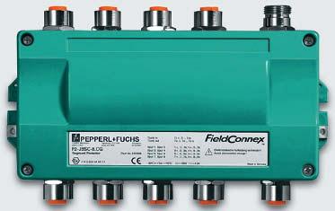
16 Junction Box and Segment Protector Segment Protector 8-spur, connectors 7/8 Segment Protector 4-spur, stainless steel housing Segment Protector DIN Rail version 16
17 Segment Protectors FieldConnex Segment Protectors offer, on top of the functionalities of Junction Boxes, short circuit current limitation and overload protection for each spur. This ensures that a fault at any spur does not have any negative feedback on the remaining segment. The unaffected devices continue communicating and the faulty spur can easily be located. The short circuit is indicated by LED, and after rectification of the problem the Segment Protector resets automatically so the spur resumes operation as normal. For chicken-foot topologies Segment Protectors are available with connection points for up to twelve spurs, too. Technical Data Junction boxes Segment Protectors Available housing types F2 F3 F4 F6 R F2 F6 R details see mechanical data Number of outputs 4, 6, , 6, 8 8 4, 6, 8 4, 6, 8 8, 12 Application, explosion protection general purpose, none x x x x x Non-incendive for Zone 2 / Class I Div. 2, Ex na[l] x x x For flameproof Ex d devices, Zone 1 / Class I Div. 2, Ex me x Intrinsically safe, Zone 1 / Class I, Div. 1, Ex i x x x x x Electrical data Supply, trunk Rated voltage max. 35 V DC max. 35 V DC Rated current max. 4.5 A max. 4.5 A Rated current Ex i versions max. 3 A n.a. Outputs Rated voltage max. 35 V DC max. 35 V DC Rated current max. 4.5 A max. 40 ma Rated current Ex i versions max. 3 A n.a. Short circuit current n.a. max. 45 ma Mechanical data Housing types F2 F3 F4 F6 R Material field mountable aluminium housing field mountable Housing for cabinet stainless steel installation on DIN rail housing Protection degree IP67 IP66 IP20 Dimensions (WxLxH) 258 x 160 x 84 mm 175 x 102 x 58 mm 125 x 97 x 58 mm 320 x 220 x 86 mm 217 x 100 x 74 mm Cable connections Terminals 2.5 mm 2 cross-section x x x x x Cable glands (*) x x x x Plug connectors (**) x x x x For detailed information please refer to the data sheets and the electronic configuration tool at (*) cable gland materials: plastic, nickel plated brass, stainless steel, also available in nickel plated brass for armored cables (**) plug connectors M12x1 or 7/8, each available in nickel plated brass or stainless steel 17


18 FieldBarrier Benefits Allows the maximum number of fieldbus devices per segment even in hazardous areas Combines three essential fieldbus topology functions in one unit Distributes the fieldbus trunk for easy connection of field devices Connects intrinsically safe fieldbus devices to non-ex Power Supplies Protects fieldbus segments against influences from short circuits Installation in Zone 1 / Class I, Div. 2, close to the devices, saves on cabling No need to use Ex d explosion protection No external terminators necessary Huge variety of housing and cable connection types meet every plant s requirements FieldBarrier with cable glands System solution three FieldBarriers in customized stainless steel cabinet FieldBarrier with stainless steel housing 18
19 Function The FieldConnex FieldBarrier is a highly sophisticated fieldbus distribution module and combines three essential physical layer functions: Distribution of the fieldbus trunk to up to four connection points for field devices Short circuit limitation for each individual device connection Use of the comfortable explosion protection method Intrinsic Safety for the field devices. The FieldBarrier is the central element of the future-proof Fieldbus Barrier Power Supply Concept. It allows to utilize the benefits of intrinsically safe field devices while doing away with the limitations in terms of supply power and topology size one typically encounters in hazardous areas. The power for the field devices is fed into the fieldbus segment by standard fieldbus power supplies without energy limitation for explosion protection. The trunk cable leading into the hazardous area can be installed in explosion protection method increased safety Ex e or Div. 2 wiring methods. Several FieldBarriers can be daisy-chained on the trunk, each one offering four outputs to connect field devices in explosion protection method intrinsic safety Ex i. This allows to service the field devices without the need for a hot work permit. Each output provides 40 ma supply current and is in accordance with FISCO and Entity concept. Up to 120 m of cable can be connected to an output and operated without an individual fieldbus terminator. A fault at one output line has no negative influence on the trunk or the other outputs due to the individual short circuit and overload protection of each output. The fault is indicated by LED, an automatic reset resumes the normal operation of the output line after the problem is fixed. The design of the FieldBarrier ensures high reliability and long-term secure operation. To meet the various requirements of all the different applications, even in harsh environments, the FieldBarrier is available in most housing variants mentioned with the FieldConnex Junction Boxes. Technical Data F2D0-FB-Ex4.* F6D0-FB-Ex4.* RD0-FB-Ex4 Housing type (*) field mountable field mountable Housing for aluminium housing stainless steel housing cabinet installation on DIN rail Electrical data Trunk Rated voltage V DC V DC V DC Rated current (**) without load: 25 ma at 16 V / 22 ma at 32 V 20 ma load per output : 121 ma at 16 V / 74 ma at 32 V 40 ma load per output : 230 ma at 16 V / 125 ma at 32 V short circuit on all outputs: 255 ma at 16 V / 135 ma at 32 V Terminating impedance 100 Ohm, switchable 100 Ohm, switchable 100 Ohm, switchable Four outputs, each Rated voltage min. 10 V at 40 ma min. 10 V at 40 ma min. 10 V at 40 ma Rated current max. 40 ma max. 40 ma max. 40 ma Short circuit current max. 50 ma max. 50 ma max. 50 ma Explosion Protection Trunk connection Increased safety Ex e Increased safety Ex e Increased safety Ex e Output connections Intrinsic safety Ex ia Intrinsic safety Ex ia Intrinsic safety Ex ia Function unit Encapsulation Ex me Encapsulation Ex me Encapsulation Ex me Mechanical data (*) Cable connections terminals 2.5 mm 2 cross-section or plug connectors Housing (WxLxH) 258 x 160 x 84 mm 320 x 220 x 86 mm 217 x 100 x 74 mm Protection degree IP 67 IP 66 IP 20 (*) for available housing and cable connection variants please refer to the electronic configuration tool (**) for detailed calculation please refer to the FieldConnex Segment Checker Software Tool For detailed information please refer to data sheets and downloadable software tools at 19


20 Fieldbus Process Interfaces Benefits Valve Coupler Easy integration of binary input and output signals into the fieldbus communication Efficient control of four solenoid valves by means of one fieldbus address Integrated end position control with two limit switches per valve Power supply to valves via the fieldbus cable Save installation in Zone 1 / Class I, Div. 1 due to intrinsic safety according to FISCO and Entity Partial stroke test and other software functions integrated Lead breakage and short circuit monitoring for each conventional signal cable Galvanic isolation between FF H1 segment and valve connections Valve Coupler for four intrinsically safe solenoid valves Benefits Fieldbus-Pneumatic Interface All the benefits of the FieldConnex Valve Coupler, and even more: Actuation of heavy-duty pneumatic control valves by means of fieldbus communication Up to 32 control valves are fed and controlled by just one fieldbus cable and one compressed air supply Sturdy stainless steel housings for harsh environments Fieldbus-Pneumatic Interface for 12 pneumatic control valves System solution: Topology with FieldBarrier and Fieldbus-Pneumatic Interface for 32 control valves in customized stainless steel cabinet 20 93_1107_15: Power Conditioner for four fieldbus segments on motherboard with DCS-specific system connectors
21 Function The FieldConnex Valve Coupler is designed to connect low-power solenoid valves to a FOUNDATION Fieldbus H1 segment. Four valves can be controlled by one fieldbus address. The valve coupler translates the digital fieldbus signal to a binary output signal for actuation of the valve and vice versa integrates the end position detection from the valve s proximity switches into a fieldbus telegram. The 2:1 wiring method is used for wiring the end position indicators which enables further savings on cables. The Valve Coupler can be installed close to the valves in Zone 1 / Class I, Div. 1 of a hazardous area. The valves themselves can be located in Zone 0 / Class I, Div. 1. Power is supplied to the Valve Coupler via the fieldbus cable, which is also used for data exchange, all parameter assignments, alarms and return messages. No additional devices or wiring are needed. In accordance with the fieldbus philosophy, monitoring and diagnostic measures are included in the field device. The Valve Coupler automatically monitors the runtime and breakaway time of the valve, conducts stroke tests in either valve position, records lead breakage or short circuits on the binary signal cables and generates alarm messages. Furthermore it enhances the plant availability due to galvanic isolation between the fieldbus segment and each valve connection point. The Fieldbus-Pneumatic Interface is a system solution out of the FieldConnex portfolio, combining the Valve Coupler with solenoid and amplifier valves in one convenient housing. The only required connections on the supply side are the FOUNDATION Fieldbus H1 and the pressure air line. The connection to the heavy-duty pneumatic control valves is done quickly and easily by just attaching the pneumatic hoses and binary signal lines to the pre-fabricated connection points. The Valve Coupler forms the communication interface, connecting four valves to one fieldbus address. Thus the number of connectable valves can be increased in steps of four. The Valve Coupler actuates the integrated solenoid valves, which in turn open or close the pneumatic control valves. 3/2-way and 5/2-way solenoid valves can be combined as desired. For larger installations the FieldConnex FieldBarrier can be incorporated into the interface housing, thus allowing to control a multitude of pneumatic valves via just one fieldbus cable. Technical Data Valve coupler FD0-VC-Ex4.FF Fieldbus-Pneumatic Interface Electrical data Fieldbus Connection Rated voltage 9 32 V 9 32 V Rated current max. 23 ma Depending on number of Valve Couplers Binary inputs Sensor supply voltage 5 V 5 V Sensor supply current 5 ma 5 ma Max. cycle time 8 x 12.5 ms 8 x 12.5 ms Binary outputs Output voltage V Operating current 1 ma Explosion Protection Intrinsically safe according to FISCO and Entity Intrinsically safe according to FISCO and Entity Pneumatical data Solenoid valve type SAMSOMATIC 3756 / 3964 Switching 3/2-way and 5/2-way combinable Central compressed air supply max. 6 bar Mechnical Housing Field mountable Customizable stainless steel field housing Dimensions 187 x 150 x 46 mm Depending on housing type Protection degree IP65 IP66 For detailed information please refer to data sheets and documentation at 21


 FieldConnex Micro Cord Set (4-pin M12x1")
22 Cables and Cord Sets Fieldbus Cable type A Benefits Fieldbus cables Type A fieldbus cable as recommended in the Fieldbus Foundation application guide Meets requirements of IEC as well as FISCO For indoor and outdoor applications Resistant against sunlight and UV radiation Armored versions for harsh environments Available in recommended colors: orange for Non-IS applications blue for IS applications Available as bulk cable on reels in standard lengths Fieldbus Cable type A with additional armor Mini Cord Set with 7/8 connector Benefits Cord Sets Pre-configured fieldbus type A cables with either male or female connector on one side and flying leads on the other side Sturdy connectors for all environments with either stainless steel or epoxy coated coupling nuts Solid termination at the fieldbus distribution module Enables quick disconnection of field device by means of connectors Available in different colors and lengths of 2 m, 5 m or 10 m as versions: FieldConnex Mini Cord Set (4-pin 7/8" connector) FieldConnex Micro Cord Set (4-pin M12x1 connector) 22
 conductors with a drain wire and overall foil shield. They meet all requirements of the Fieldbus Foundation Installation Guidelines as well as FISCO and FNICO.")

23 Function The FieldConnex Fieldbus Cables are designed specifically for use in fieldbus installations according to IEC They feature two 0.8 mm (18 AWG) conductors with a drain wire and overall foil shield. They meet all requirements of the Fieldbus Foundation Installation Guidelines as well as FISCO and FNICO. Cables, Cord Sets and Extension cables can be used for indoor and outdoor installations. The sheathing materials are safe against UV radiation and have low toxic emissions according to fire safety regulations. They are available in all recommended colors for different applications and explosion protection methods. Fieldbus bulk cables are available in higher wire gauges, too, to reduce attenuation in extended topologies. They come on reels in standard lengths for efficient trunk installations as well as hard wiring of spurs on both field device and fieldbus distribution modules such as Junction Box, Segment Protector or FieldBarrier. For enhanced safety and harsh environments there are versions with additional armoring. FieldConnex Cord sets will be used for the interconnection of a field device with a connector to a Junction Box, Segment Protector or FieldBarrier with cable glands. Thus it is easy to quickly disconnect the field device while the passive communication topology remains solidly terminated. The connector can be either male or female, all recommended sheathing colors are available. FieldConnex Extension Cables allow a quick and easy installation of the fieldbus topology by reducing the need for cable terminations. They feature pre-configured male and female connectors, thus guaranteeing faultless connections by omitting the danger of wrong wire terminations. Extension Cables are the best choice for modifications or elongations of existing networks. For detailed information please refer to documentation and electronic configuration tool at Benefits Extension Cables Pre-configured fieldbus type A cables with male connector on one side and female on the other side Sturdy connectors for all environments with either stainless steel or epoxy coated coupling nuts Quick and easy installation with no danger of wrong termination at both fieldbus distribution module and field device Enables quick disconnection of field device Easy modification and elongation of exististing installations Available in different colors and lengthes of 2 m, 5 m or 10 m as versions: FieldConnex Mini Extension Cable (4-pin 7/8" connectors) FieldConnex Micro Extension Cable (4-pin M12x1 connectors) Mini Extension Cable with 7/8 connectors 23


24 Fieldbus Terminators Benefits Secure clear fieldbus communication by avoiding signal reflections According to fieldbus standard IEC Intrinsically safe versions according to FISCO and Entity Versions for explosion protection flameproof Ex d Field mountable versions in sturdy screw-in housings IP67 Various thread versions to fit in most field devices Versions for cabinet installation on DIN rail Fieldbus Terminator for cabinet installation on DIN rail Fieldbus Terminator for field installation in sturdy screw-in housing Function To ensure a clear, safe digital fieldbus communication any signal reflections in the fielbus lines have to be avoided. Therefore each fieldbus segment requires specific terminating impedances at the opposing ends. With the FieldConnex System the appropriate fieldbus terminators are integrated in the power supply modules. At the field side the termination can be switched on at most of the FieldConnex modules. In cases where external terminators are required FieldConnex offers a variety of terminators either for cabinet installation on DIN rail or in sturdy housings for installation in hazardous environments. The latter are available for different explosion protection methods and with various threads for installation at the field device. Technical Data KMD0-FT-Ex F*-FT-I F*-FT-D Explosion protection Intrinsically safe Ex i Intrinsically safe Ex i Flameproof Ex d Housing type For cabinet installation on DIN Rail Screw-in housing for field installation Electrical Rated voltage max. 32 V DC max. 32 V DC max. 32 V DC Mechanical Connections Terminal 2.5 mm 2 Cables 0.75 mm 2 Cables 0.75 mm 2 Housing (WxLxH) 20 x 93 x 65 mm 23 x 75 x 23 mm 23 x 75 x 23 mm Protection degree IP20 IP67 IP67 Thread versions n.a. FS: ISO M20 x 1.5 FS: ISO M20 x 1.5 FP: PG 13.5 FP: PG 13.5 FN: 1/2" NPT FN: 1/2" NPT For detailed information please refer to data sheets at 24
25 Surge Protectors Modular Surge Protector, complete unit for cabinet installation Benefits Protects fieldbus host system and instruments against voltage surges and spikes Versions for general purpose applications as well as intrinsically safe according to FISCO and Entity Sturdy field mountable versions for Ex d field devices DIN rail versions can serve as marshalling terminal Modular DIN rail system with base and protection modules separately for easy exchange and testing Can be used for 4 20 ma signal loops with HART, too Modular Surge Protector, base module for DIN rail mounting Surge Protector for field installation in sturdy screw-in housing Function FieldConnex Surge Protection Devices protect fieldbus devices safely from damages caused by voltage surges and lightning strikes. They allow the coordinated use in the EMC-orientated Lightning Protection Zones Concept in accordance with IEC The modular Surge Protectors consist of various base and protection modules. The base modules are designed for cabinet installation on DIN rail and hold the removable protection module. Removal of the latter interrupts the signal transmission or leaves it unimpaired, depending on the base module version. FieldConnex Surge Protectors are also available in sturdy screw-in housings for installation at the field devices in harsh environments, either in explosion protection method Ex i or Ex d. Technical Data DP-LBF-* DP-LBF-I* F*-LBF-I* F*-LBF-D* Explosion protection None Intrinsically safe Ex i Intrinsically safe Ex i Flameproof Ex d Housing type For cabinet installation on DIN Rail Screw-in housing for field installation Electrical Rated Voltage 34.8 V 34.8 V 32 V 32 V Rated Current 1 A 500 ma 550 ma 550 ma Max. Surge Current 20 ka 20 ka 20 ka 20 ka Voltage protection level at max. rated current 60 V 60 V 60 V 60 V Mechanical Connections Terminal 2.5 mm 2 Terminal 2.5 mm 2 Cables 1.0 mm 2 Cables 1.0 mm 2 Housing (WxLxH) 12 x 90 x 58 mm 12 x 90 x 58 mm 23 x 75 x 23 mm 23 x 75 x 23 mm Protection degree IP20 IP20 IP67 IP67 Thread versions n.a. n.a. FS: ISO M20 x 1.5 FS: ISO M20 x 1.5 FP: PG 13.5 FP: PG 13.5 FN: 1/2" NPT FN: 1/2" NPT For detailed information please refer to data sheets at 25

26 Accessories, Tools and Services Segment Checker topology design tool Power Rail with two Power Feed Modules FieldConnex Fieldbus Installation technology forms the basis for efficient and safe fieldbus communication in a multitude of environments and applications in the processing industry. In order to support the design of appropriate fieldbus topologies for all specific requirements Pepperl+Fuchs offers a variety of convenient accessories, tools and services: Installation materials and power connection modules as shown in the table page 27 The Segment Checker software tool allows the easy design of fieldbus topologies based on the Fieldbus Barrier Concept, following the recommendations of the FuRIOS Enduser Study The Fieldbus Distributors Configuration software tool helps to find the appropriate housing and cable connection variant of either Junction Box, Segment Protector or FieldBarrier All necessary integration software such as DD and CF files are available for download in the latest versions The FieldConnex Installation and Wiring Guide gives a comprehensive introduction into fieldbus topology design with a lot of helpful hints. It is available as free download in Adobe pdf format. Manuals and installation instructions of all FieldConnex System Modules are available in pdf format, too Application reports and publications on latest developments and experiences in the fast-moving field of fieldbus technology offer state-of-the-art knowledge The Pepperl+Fuchs Project Team offers extensive experience in fieldbus projects management and custom designs of FieldConnex applications and system solutions The Pepperl+Fuchs Support Team is on stand-by to answer any questions on design, commissioning and operation of fieldbus applications 26
27 Accessories Module Designation Description Picture Power Rail PR-03 Insert module with snap lock for DIN Rail according to DIN EN 50022, standard length 500 mm. Power Rail UPR-03 Universal Power Rail with DIN rail and cover, standard length 2000 mm. Power Feed Module KFD2-EB2.B Provides power to the Power Rail with 24 V DC at a maximum current of 4 A. Error message signal can be transmitted on the Power Rail. Power Feed Module KFD2-EB-D2A.B Provides power to the Power Rail redundantly from two power supplies with 24 V DC at a maximum current of 2 A, integrated decoupling diodes, with error message signal on the Power Rail. Power Feed Module KFD2-EB-R2A.B Provides power to the Power Rail with 24 V DC at a maximum current of 2 A. To setup a redundant system, a second device can be used. With error message signal on the Power Rail. Please don't hesitate to visit or contact your local Pepperl+Fuchs representative. 27

28 AUTOMATION Signals for the World Of Automation Worldwide Headquarters Pepperl+Fuchs GmbH Königsberger Allee Mannheim Germany Tel Fax USA Headquarters Pepperl+Fuchs Inc Enterprise Parkway Twinsburg, Ohio Cleveland-USA Tel Fax Asia Pacific Headquarters Pepperl+Fuchs Pte Ltd. P+F Building 18 Ayer Rajah Crescent Singapore Tel Fax Subject to reasonable modifications due to technical advances Copyright PEPPERL+FUCHS Printed in Germany Part. No /04 00
PROCESS AUTOMATION INSTALLATION TECHNOLOGY FOR PROFIBUS PA
 PROCESS AUTOMATION INSTALLATION TECHNOLOGY FOR PROFIBUS PA SYSTEM OVERVIEW AND CONTENT HOST Plant Communication page 4 with Fieldbus Benefit from the future proof, enabling technology page 12 Segment coupler
PROCESS AUTOMATION YOUR PARTNER FOR INDUSTRY-SPECIFIC INSTALLATION SOLUTIONS FIELD JUNCTION BOX
 PROCESS AUTOMATION YOUR PARTNER FOR INDUSTRY-SPECIFIC INSTALLATION SOLUTIONS FIELD JUNCTION BOX OUR COMPONENTS... CONFIGURABLE TO YOUR NEEDS No application is like the others; every application always
New FOUNDATION Fieldbus Interface Techniques Increased Availability and Reduced Costs. Andreas Agostin Pepperl+Fuchs
 New FOUNDATION Fieldbus Interface Techniques Increased Availability and Reduced Costs Andreas Agostin Pepperl+Fuchs Abstract InfraServ Hoechst and Aventis Pharma of Germany performed a comparison study
FF Physical Layer Components
 FF Physical Layer Components Best Practices Binoy Kamath AGM Project Pursuit Pepperl+Fuchs India Pvt. LTd.,Bangalore Agenda Introduction to FF and FF Physical Layer FF Physical Layer Components FF Wiring
Distributed Intrinsically Safe Fieldbus Applications
 Application Note FB01-1 - Distributed Intrinsically Safe Fieldbus Applications Emerson Process Management DeltaV DCS System Pepperl+Fuchs June 2003 Application Note FB01-2 - c Pepperl+Fuchs Inc. All rights
Design Benefits. Teo Puay Yong Pepperl+Fuchs. On Behalf of FF Marketing Society. The Future is Digital. 1 The Future is Digital
 Design Benefits The Future is Digital Teo Puay Yong Pepperl+Fuchs On Behalf of FF Marketing Society 1 The Future is Digital Design Benefits from Applying Foundation Fieldbus Bus structure and Wiring Loop
MANUAL Surge Protectors
 PROCESS AUTOMATION MANUAL Surge Protectors DP-LBF-I1.36.DE and DP-LBF- I1.36.IE With regard to the supply of products, the current issue of the following document is applicable: The General Terms of Delivery
7/2005. Reprint. Oldenbourg. Automation Technology in Practice. Breakthrough in Fieldbus technology High Power Trunk concepts.
 7/2005 July Automation Technology in Practice Breakthrough in Fieldbus technology High Power Trunk concepts Reprint Oldenbourg 3 Breakthrough in Fieldbus technology High Power Trunk concepts Do we see
5 Fieldbus Technology
 5 Fieldbus Technology Ex e / Ex i 10922E00 The s Ex e/ex i connect intrinsically safe Foundation Fieldbus H1 or Profibus PA field devices to a non-intrinsically safe / Ex e trunk. Up to four intrinsically
The High Power Trunk Alternative to FISCO and FNICO
 The High Power Trunk Alternative to FISCO and FNICO Bernd Schuessler, Business Development Manager Pepperl+Fuchs Twinsburg, OH 330-486-0002 www.fieldconnex.info End users throughout the Fieldbus world
MARINE CERTIFIED PRODUCTS BY PEPPERL+FUCHS
 FIELDBUS Power Hub with Power Supply Modules KLD2-FBPS-1.25.360 HD2-FBPS-1.25.360 HD2-FBPS-1.500 HD2-FBPS-1.23.500 HD2-FBPS-1.17.500 Fieldbus Power Supply, 25 V/360 ma, stand-alone, DIN-rail mountable
Introduction to Fieldbus Foundation Physical Layer
 Introduction to Fieldbus Foundation Physical Layer Fazi Hashim MTL Muhammad Syafiq bin Hamid KLAESB Product Sales /Application Engineer Email: muhammad.syafiq@klaesb.com Fieldbus What is fieldbus Benefits
Trusted Strategic Partners in Process Automation. Alliance Member
 Trusted Strategic Partners in Process Automation Alliance Member Together with Pepperl+Fuchs, the Emerson Alliance Program provides a total automation solution Emerson and Pepperl+Fuchs have worked together
Operating Instructions
 Introduction To protect the signal lines of field devices and systems in the cabinet against lightning. Pepperl+Fuchs covers the complete range of Surge Protection Barriers. Housing types Depending on
FACTORY AUTOMATION. Manual IVI-KHD2-4HD1. Control Unit
 FACTORY AUTOMATION Manual Control Unit With regard to the supply of products, the current issue of the following document is applicable: The General Terms of Delivery for Products and Services of the Electrical
Benefits derived from the FF specification FF-831
 Foundation Fieldbus End Users Council Australia Inc. 9 Corcoran St Duncraig, WA 6023 P.O. Box Z5546 Perth, WA 6831 Benefits derived from the FF specification FF-831 Why we need it, and why it improves
MANUAL SEGMENT CHECKER
 PROCESS AUTOMATION MANUAL SEGMENT CHECKER A UNIVERSAL AND EASY-TO- USE SEGMENT DESIGN TOOL FOR FIELDBUS NETWORKS With regard to the supply of products, the current issue of the following document is applicable:
FieldIT Multi Barrier NMB204/NMB204-EX (MB 204/MB 204-Ex)
") Data Sheet FieldIT Multi Barrier NMB204/NMB204-EX (MB 204/MB 204-Ex) Intrinsically safe power supply of up to 31 stations on the bus cascadable multi barrier Intrinsically safe connection of up to 4 field
Data Sheet FieldIT Multi Barrier NMB204/NMB204-EX (MB 204/MB 204-Ex) Intrinsically safe power supply of up to 31 stations on the bus cascadable multi barrier Intrinsically safe connection of up to 4 field
DC Power Considerations for Intrinsically Safe Applications
 Chapter 3 Intrinsically Safe Fieldbus Applications This chapter provides information about fieldbus applications that provide Intrinsically Safe (IS) power to fieldbus devices located in hazardous areas.
FACTORY AUTOMATION. Manual IVI-KHD2-4HD3. Control Unit with 8 Inputs/Outputs
 FACTORY AUTOMATION Manual Control Unit with 8 Inputs/Outputs With regard to the supply of products, the current issue of the following document is applicable: The General Terms of Delivery for Products
PROCESS AUTOMATION SIMPLIFY PROCESSES FIELDCONNEX INFRASTRUCTURE FOR PROFIBUS PA
 PROCESS AUTOMATION SIMPLIFY PROCESSES FIELDCONNEX INFRASTRUCTURE FOR PROFIBUS PA SIMPLIFY PROCESSES The best solutions are usually very simple The fieldbus is a perfect example of simplicity at its best.
PROCESS AUTOMATION INSTRUCTION MANUAL FIELDBUS SURGE PROTECTOR F*-LBF-I1.32 F*-LBF-D1.32
 PROCESS AUTOMATION INSTRUCTION MANUAL FIELDBUS SURGE PROTECTOR F*-LBF-I1.32 F*-LBF-D1.32 With regard to the supply of products, the current issue of the following document is applicable: The General Terms
F101, F102, F104. Relcom Installation Instructions. Fieldbus Power Supply F101-PS
 F101, F102, F104 Fieldbus Power Supply F101-PS Installation Instructions Relcom www.mtl-fieldbus.com CONTENTS PAGE 1 OVERVIEW 2 2 DESCRIPTION 2 3 COMPONENTS AND ACCESSORIES 2 4 MECHANICAL 3 4.1 Mounting
PROFIBUS-PA Positioner Type 3785
 PROFIBUS-PA Positioner Type 3785 Application Single-acting or double-acting PROFIBUS-PA positioner for attachment to pneumatic control valves. Rated travel from 7.5 to 120 mm Opening angle up to 120 Smart,
PROCESS AUTOMATION MANUAL FIELDBUS POWER HUB INVENSYS
 PROCESS AUTOMATION MANUAL FIELDBUS POWER HUB INVENSYS Advanced high performance power supplies and conditioner With regard to the supply of products, the current issue of the following document is applicable:
10 Mb/s Single Twisted Pair Ethernet Process Industry Requirements Steffen Graber Pepperl+Fuchs
 10 Mb/s Single Twisted Pair Ethernet Process Industry Requirements Steffen Graber Pepperl+Fuchs IEEE802.3 10 Mb/s Single Twisted Pair Ethernet Study Group 9/8/2016 1 Overview Introduction Current bus Infrastructure
FACTORY AUTOMATION QUICK START GUIDE IC-KP-*
 FACTORY AUTOMATION QUICK START GUIDE IC-KP-* IDENTControl units With regard to the supply of products, the current issue of the following document is applicable: The General Terms of Delivery for Products
Assembly. Front view. LED yellow: Relay output. LED red: LB/SC Power Rail
 Switch Amplifier Features Assembly -channel isolated barrier 4 V DC supply (Power Rail) Dry contact or NAMUR inputs Relay contact output Line fault detection (LFD) Reversible mode of operation Up to SIL
Fieldbus Foundation TM Physical Design. Joseph Khoo AP Regional Sales Director R.Stahl
 Fieldbus Foundation M Physical Design Joseph Khoo AP Regional Sales Director R.Stahl 1 Fieldbus How is fieldbus different to 4-20mA? Wiring and Interconnection Components opologies Design tools Installation
FACTORY AUTOMATION INSTRUCTION MANUAL. AS-Interface Safety at Work VAA-2E-G4-SN. Version 1.2
 FACTORY AUTOMATION INSTRUCTION MANUAL AS-Interface Safety at Work VAA-2E-G4-SN Version 1.2 With regard to the supply of products, the current issue of the following document is applicable: The General
FOUNDATION. Product Overview. Foundation Fieldbus
 FOUNDATION Product Overview Foundation Fieldbus PROFIBUS PA Process Fieldbus wired infrastructure Control cabinet The Fieldbus (FB ) line of modular fieldbus components offers connectivity from the process
Inductive sensor NI3-EG08K-Y1-H1341
 ATEX category II 1 G, Ex zone 0 ATEX category II 1 D, Ex zone 20 SIL2 as per IEC 61508 Threaded barrel, M8 x 1 Stainless steel, 1.4427 SO DC 2-wire, nom. 8.2 VDC Output acc. to DIN EN 60947-5-6 (NA- MUR)
Assembly. Front view. LED yellow/red: Status output Ι/ Fault signal Function. Switch Power Rail
 Switch Amplifier KCD-SR-Ex.LB Features Assembly -channel isolated barrier V DC supply (Power Rail) Dry contact or NAMUR inputs Usable as signal splitter ( input and outputs) Relay contact output Fault
Inductive sensor For rotary actuators NI4-DSU35-2Y1X2-H1140
 ATEX category II 2 G, Ex zone 1 ATEX category II 1 D, Ex zone 20 SIL2 (Low Demand Mode) acc. to IEC 61508, PL c acc. to ISO 13849-1 at HFT0 SIL3 (All Demand Mode) acc. to IEC 61508, PL e acc. to ISO 13849-1
Magnetic Field Sensor Magnetic-inductive Proximity Sensor BIM-EG08-Y1X-H1341
 ATEX category II 1 G, Ex zone 0 ATEX category II 1 D, Ex zone 20 SIL2 (Low Demand Mode) acc. to IEC 61508, PL c acc. to ISO 13849-1 at HFT0 SIL3 (All Demand Mode) acc. to IEC 61508, PL e acc. to ISO 13849-1
Assembly MAU. MUX 4 Channels 8 Channels Zone 1
 Multi-Input/Output Device for Cabinet Installation Features Assembly For discrete inputs and outputs Installation in Zone 1/Div. 1, intrinsically safe Sensors in Zone 0/Div. 1 Connection to fieldbus acc.
MINI MCR-SL-PT100-UI(-SP)(-NC)
(-NC)") Configurable Temperature Transducer for PT100 Data Sheet 04/2005 Functions MINI MCR-SL-PT100-UI(-SP)(-NC) is a configurable 3-way isolated temperature measuring transducer. It is suitable for the connection
Configurable Temperature Transducer for PT100 Data Sheet 04/2005 Functions MINI MCR-SL-PT100-UI(-SP)(-NC) is a configurable 3-way isolated temperature measuring transducer. It is suitable for the connection
FACTORY AUTOMATION MANUAL PMI360D-F130-IE8-V15 INDUCTIVE POSITIONING SYSTEM
 FACTORY AUTOMATION MANUAL PMI360D-F130-IE8-V15 INDUCTIVE POSITIONING SYSTEM With regard to the supply of products, the current issue of the following document is applicable: The General Terms of Delivery
S900 Remote I/O System Intrinsic safety in the field ABB
 S900 Remote I/O System Intrinsic safety in the field ABB 2 S900 REMOTE I/O SYSTEM INTRINSIC SAFETY IN THE FIELD The S900 Remote I/O System 01 Example of Field housing FH660S in stainless steel with complete
Inductive sensor BI1.5-EG08-Y1-H1341
 ATEX category II 1 G, Ex zone 0 ATEX category II 1 D, Ex zone 20 SIL2 (Low Demand Mode) acc. to IEC 61508, PL c acc. to ISO 13849-1 at HFT0 SIL3 (All Demand Mode) acc. to IEC 61508, PL e acc. to ISO 13849-1
FACTORY AUTOMATION INSTRUCTION MANUAL INDUCTIVE POSITIONING SYSTEM -F90
 FACTORY AUTOMATION INSTRUCTION MANUAL INDUCTIVE POSITIONING SYSTEM -F90 . 1 System overview............................................. 5 2 Sensor versions..............................................
Termination Board FC-GPCS-RIO16-PF. Features. Assembly. Function. Connection USIO/UPIO 24 V DC (I), 24 V DC (II) Fault. Zone 0, 1, 2 Div.
, 24 V DC (II) Fault. Zone 0, 1, 2 Div.") Features Assembly System board for Honeywell Universal Safety IO System board for Honeywell Universal Process IO For 6-channel cards USIO and UPIO For 6 modules Recommended modules: HiC8R (DI), HiC85R
Features Assembly System board for Honeywell Universal Safety IO System board for Honeywell Universal Process IO For 6-channel cards USIO and UPIO For 6 modules Recommended modules: HiC8R (DI), HiC85R
PROFIBUS and Integrated Safety architectures in Ex areas
 PROFIBUS and Integrated Safety architectures in Ex areas Since 1989, PROFIBUS has developed into a worldwide leading fieldbus system used in machine and process plant automation. The main reason why PROFIBUS
FieldLink process networking
 FieldLink process networking Enclosures Junction module (JM) StoneL s Junction Module (JM) enclosure is an environmetally hardened platform which is suitable for use in the most extreme corrosive and hazardous
FEATURES DESCRIPTION
 JUNCTION BOXES FEATURES Allows easy and safe device connections to the fieldbus (Fo u n d at i o n fieldbus TM, PROFIBUS) HART and even for standard instrumentation wiring 4-20 ma; Ideal for coupling sensors,
Tutorial: Characteristics & Requirements of Physical Networks in the Process Industry
 Tutorial: Characteristics & Requirements of Physical Networks in the Process Industry IEEE802.3cg 10 Mb/s Single Twisted Pair Ethernet Task Force Brian Franchuk Martin Zielinski Introduction 2 Pertinent
Inductive sensor BI1.5-EG08-Y1-H1341
 ATEX category II 1 G, Ex zone 0 ATEX category II 1 D, Ex zone 20 SIL2 (Low Demand Mode) acc. to IEC 61508, PL c acc. to ISO 13849-1 at HFT0 SIL3 (All Demand Mode) acc. to IEC 61508, PL e acc. to ISO 13849-1
FACTORY AUTOMATION MANUAL WCS-MBG110 WCS MODBUS RTU INTERFACE MODULE
 FACTORY AUTOMATION MANUAL WCS MODBUS RTU INTERFACE MODULE With regard to the supply of products, the current issue of the following document is applicable: The General Terms of Delivery for Products and
Inductive sensor For rotary actuators NI4-DSU35TC-2Y1X2/S933
 ATEX category II 2 G, Ex zone 1 ATEX category II 1 D, Ex zone 20 SIL2 (Low Demand Mode) acc. to IEC 61508, PL c acc. to ISO 13849-1 at HFT0 SIL3 (All Demand Mode) acc. to IEC 61508, PL e acc. to ISO 13849-1
MANUAL VAA-2E2A-G12-SAJ/EA2L Original Instructions Version 1.0
 FACTORY AUTOMATION MANUAL VAA-2E2A-G12-SAJ/EA2L Original Instructions Version 1.0 SAFETY AT WORK With regard to the supply of products, the current issue of the following document is applicable: The General
Segment Protector for Cabinet Installation R2-SP-IC* Features. Assembly. Function. Connection. Trunk, Ex na non-arcing. Spur.
 egment Protector for Cabinet nstallation Features Assembly 4... 12 outputs Ex ic (FCO or Entity) or non-incendive (Div 2) Advanced fault isolation at the spur egment Protector in Zone 2/Div. 2 nstruments
Inductive dual sensor For rotary actuators NI4-DSU35TC-2Y1X2/S933
 ATEX category II 2 G, Ex zone 1 ATEX category II 1 D, Ex zone 20 SIL2 as per IEC 61508 Rectangular, housing DSU35 Plastic, PP-GF30-VO Two outputs for monitoring the position of rotary actuators Mounting
FACTORY AUTOMATION. Manual Speed Monitor KFU8-DW-1.D
 FACTORY AUTOMATION Manual Speed Monitor KFU8-DW-.D With regard to the supply of products, the current issue of the following document is applicable: The General Terms of Delivery for Products and Services
Assembly MAU. MUX 4 Channels 8 Channels Zone 1
 Multi-Input/Output Device for Cabinet Installation Features Assembly For discrete inputs and outputs Installation in Zone 1/Div. 1, intrinsically safe Sensors in Zone 0/Div. 1 Connection to fieldbus acc.
Termination Board FC-GPCS-SAI16-PF. Features. Assembly. Function. Connection. SAI-1620m HART 24 V DC (I), 24 V DC (II) Fault. Zone 0, 1, 2 Div.
, 24 V DC (II) Fault. Zone 0, 1, 2 Div.") Features Assembly System board for Honeywell Safety Manager For 6-channel AI card SAI-60m For 6 modules Recommended module: HiC05 (AI) 4 V DC supply Hazardous area: pluggable screw terminals, blue Non-hazardous
Features Assembly System board for Honeywell Safety Manager For 6-channel AI card SAI-60m For 6 modules Recommended module: HiC05 (AI) 4 V DC supply Hazardous area: pluggable screw terminals, blue Non-hazardous
MDP and FDB lightning barriers Safety for data and control systems in plants and industrial and potentially explosive
 MDP and FDB lightning barriers Safety for data and control systems in plants and industrial and potentially explosive areas THINK CONNECTED. TBS OBO Data and control systems are omnipresent in modern buildings
SOLUTIONS FOR THE PHARMACEUTICAL INDUSTRY Solutions for the Pharmaceutical Industry
 Planning and construction of super skids Solutions for the Pharmaceutical Industry Comprehensive know-how on fieldbus technology for USA TURCK Inc. 3000 Campus Drive Minneapolis, MN 55441 Phone: (763)
FOUNDATION Fieldbus Fieldbus Basics & its Benefits
 FOUNDATION Fieldbus Fieldbus Basics & its Benefits James Loh Yokogawa Engineering Asia On behalf of Fieldbus Foundation TM Vietnam FF Seminar Fieldbus Basics - Agenda 1. H1 Basic Review. 2. H1 Benefits.
Magnetic Field Sensor Magnetic-inductive Proximity Sensor BIM-M12E-Y1X-H1141
 ATEX category II 1 G, Ex zone 0 ATEX category II 1 D, Ex zone 20 SIL2 (Low Demand Mode) acc. to IEC 61508, PL c acc. to ISO 13849-1 at HFT0 SIL3 (All Demand Mode) acc. to IEC 61508, PL e acc. to ISO 13849-1
Digital Positioner 8049
 Compact digital positioner for pneumatic control valves. Positioner can be integrated into valve actuator (no external moving parts for stroke feedback) Wide range of strokes - 8 mm No steady-state air
QUICK START GUIDE IC-KP2-*
 FACTORY AUTOMATION QUICK START GUIDE IC-KP2-* IDENTControl Compact control interfaces With regard to the supply of products, the current issue of the following document is applicable: The General Terms
Digital Output Module 8-Channel Version for Zone 2 Series 9475/
 > 8-channel digital output > Intrinsically safe outputs Ex ia > For Ex i solenoid valves and display elements > Line fault monitoring per channel > Diagnostics based on NE107 > Module can be replaced in
INSTRUCTION MANUAL WCS-Interface Module, DeviceNet
 FACTORY AUTOMATION INSTRUCTION MANUAL WCS-Interface Module, DeviceNet WCS-DG210 Part. No. 202340 / DOCT-1305 / 11. june 2007 1 Working principle............................ 6 2 Installation and commissioning.................
Inductive sensor For rotary actuators NI4-DSU35TC-2Y1X2
 ATEX category II 2 G, Ex zone 1 ATEX category II 1 D, Ex zone 20 SIL2 (Low Demand Mode) acc. to IEC 61508, PL c acc. to ISO 13849-1 at HFT0 SIL3 (All Demand Mode) acc. to IEC 61508, PL e acc. to ISO 13849-1
System 6000 Electropneumatic Converters (proportional valves) Electronic Controllers Signal Converters
 Electronic Controllers Signal Converters") System 6000 Electropneumatic Converters (proportional valves) Electronic Controllers Signal Converters Edition November 2003 Information Sheet T 6000 EN Proportional valves e/p Converters Type 6 66 626
System 6000 Electropneumatic Converters (proportional valves) Electronic Controllers Signal Converters Edition November 2003 Information Sheet T 6000 EN Proportional valves e/p Converters Type 6 66 626
PSI-MODEM-SHDSL/PB. Broadband PROFIBUS extender, SHDSL PROFIBUS leased line modem. Data sheet _en_03. 1 Description. 1.
 PSI-MODEM-/PB Broadband PROFIBUS extender, PROFIBUS leased line modem Data sheet 104396_en_03 1 Description PHOENIX CONTACT 2013-08-21 1.1 Features The PROFIBUS extender can be used to easily network PROFIBUS
Segment Protector for Cabinet Installation R2-SP-IC* Features. Assembly. Function. Connection. Trunk, Ex na non-arcing. Spur.
 egment Protector for Cabinet nstallation Features Assembly 4... 12 outputs Ex ic (FCO or Entity) or non-incendive (Div 2) Advanced fault isolation at the spur egment Protector in Zone 2/Div. 2 nstruments
PROCESS AUTOMATION MANUAL. Temperature Trip Amplifier. KFD2-GU-(Ex)1 ISO9001
1 ISO9001") PROCESS AUTOMATION MANUAL Temperature Trip Amplifier KFD2-GU-(Ex)1 ISO9001 With regard to the supply of products, the current issue of the following document is applicable: The General Terms of Delivery
PROCESS AUTOMATION MANUAL Temperature Trip Amplifier KFD2-GU-(Ex)1 ISO9001 With regard to the supply of products, the current issue of the following document is applicable: The General Terms of Delivery
PROCESS AUTOMATION MANUAL. Universal Temperature Converter KCD2-UT2-(Ex)1 ISO9001
1 ISO9001") PROCESS AUTOMATION MANUAL Universal Temperature Converter KCD2-UT2-(Ex)1 ISO9001 With regard to the supply of products, the current issue of the following document is applicable: The general terms of delivery
PROCESS AUTOMATION MANUAL Universal Temperature Converter KCD2-UT2-(Ex)1 ISO9001 With regard to the supply of products, the current issue of the following document is applicable: The general terms of delivery
Series 3730 Electropneumatic Positioner Type with PROFIBUS-PA communication
 Series 3730 Electropneumatic Positioner Type 3730-4 with PROFIBUS-PA communication Application Positioner for attachment to pneumatic control valves Travels 3.6 to 200 mm Opening angle 24 to 100 Smart,
PROCESS AUTOMATION. Manual KF!!-UFT-(EX)2.D ROTATION DIRECTION INDICATOR AND CONSTANT SPEED MONITOR
2.D ROTATION DIRECTION INDICATOR AND CONSTANT SPEED MONITOR") PROCESS AUTOMATION Manual KF!!-UFT-(EX)2.D ROTATION DIRECTION INDICATOR AND CONSTANT SPEED MONITOR The General Terms of Delivery for Products and Services in the electronics industry apply, these are published
PROCESS AUTOMATION Manual KF!!-UFT-(EX)2.D ROTATION DIRECTION INDICATOR AND CONSTANT SPEED MONITOR The General Terms of Delivery for Products and Services in the electronics industry apply, these are published
PROCESS AUTOMATION. MANUAL Z-System. Zener Barriers ISO9001
 PROCESS AUTOMATION MANUAL Z-System Zener Barriers ISO9001 With regard to the supply of products, the current issue of the following document is applicable: The General Terms of Delivery for Products and
MTL8000-2/x Series Modular I/O
 -2/x Series Modular Overview Modules Modules - Overview - 2/2 components Use this option for general purpose or nonhazardous applications, or where the equipment and/or field wiring has to be mounted in
Hazardous Area Protection
 Hazardous Area Protection Global Solutions in Hazardous Area Surge and Lightning Protection Intrinsic Safety When instrumentation is installed in a potentially explosive environment steps must be taken
Digital Output Module 8-Channel Version for Zone 1 Series 9475/
 www.stahl.de > 8-channel digital output > Intrinsically safe outputs Ex ia > For Ex i solenoid valves and display elements > Additional Ex i control input for "Plant STOP" (acc. IEC61508 up to SIL2) >
FACTORY AUTOMATION TAILORED TO YOUR APPLICATION MODULAR SAFETY MONITORING UNIT
 FACTORY AUTOMATION TAILORED TO YOUR APPLICATION MODULAR SAFETY MONITORING UNIT THE SUITABLE MONITORING UNIT FOR YOUR MACHINE PROTECTION The requirements on safety systems for today's machines and installations
Termination Board. HiCTB08-SCT-44C-SC-RA. Features. Assembly. Function. Connection. 24 V DC (I), 24 V DC (II), Fault. Zone 0, 1, 2 Div.
, 24 V DC (II), Fault. Zone 0, 1, 2 Div.") Termination Board HiCTB08-SCT-C-SC-RA Features Assembly For 8 modules V DC supply Supported signal types: DI/DO/AI/TI/AO Hazardous area: screw terminals, blue Safe area: screw terminals, black Function
Termination Board HiCTB08-SCT-C-SC-RA Features Assembly For 8 modules V DC supply Supported signal types: DI/DO/AI/TI/AO Hazardous area: screw terminals, blue Safe area: screw terminals, black Function
process automation protecting your process
 process automation protecting your process PROCESS AUTOMATION For over a half century, Pepperl+Fuchs has provided new concepts for the world of process automation. Our company sets standards in quality
Installation Manual Series PQ-L. Electronic Module. Bulletin /UK
 Bulletin 5715-571 /UK Installation Manual Electronic Module Gutenbergstr. 38 41564 Kaarst, Germany Tel.: (+) 2131-513-0 Fax: (+) 2131-513-230 www.parker.com Copyright Ó 2000, Note This document and other
PHOENIX CONTACT - 05/2007
 Ex Universal Module Carrier (Motherboard) for Accommodating 3-Wire Measuring Transducers, Intrinsically Safe, for a Maximum of 8 PI Ex Modules INTERFACE Data Sheet 103030_00_en PHOENIX CONTACT - 05/2007
ABB Fieldbus Infrastructure and Network Devices An overview
 ABB Fieldbus Infrastructure and Network Devices An overview ABB ABB fieldbus devices Industrial automation with the fieldbus Fieldbus technology is becoming increasingly important throughout industry.
PROCESS AUTOMATION MANUAL F2-SP-IC*
 R PROCESS AUTOMATION MANUAL F2-SP-IC* Segment Protector With regard to the supply of products, the current issue of the following document is applicable: The General Terms of Delivery for Products and
SIRIUS Motor Management and Control Devices
 Overview is a flexible, modular motor management system for motors with constant speeds in the low-voltage performance range. It optimizes the connection between the control system and motor starter, increases
Engineering Guideline. pac-carriers Type for Honeywell system Experion Series C I/O
 Engineering Guideline pac-carriers Type 995 for Honeywell system Experion Series C I/O pac-carrier Type 995 Engineering Guideline/Honeywell 04..009 pac-carrier Type 995 Integration of conventional process
FB-6SP and FB-12SP. Block device couplers. Data sheet 3177_en_A. 2 Features. 1 Description
 Block device couplers Data sheet 3177_en_A 1 Description PHOENX CONTACT 2015-01-20 2 Features The and block couplers provide an interface between the fieldbus trunk cable and field devices on Foundation
Digital Output Module 8-Channel Version for Zone 2 Series 9475/
 > 8-channel digital output > Intrinsically safe outputs Ex ia > For Ex i solenoid valves and display elements > Line fault monitoring per channel > Diagnostics based on NE107 > Module can be replaced in
FLEX Ex Spring Clamp Terminal Base
 Installation Instructions FLEX Ex Spring Clamp Terminal Base (Cat. No. 1797-TB3S) 1 10 11 4 Only remove this cover plug if connecting another terminal base unit. 3 5 6 12 2 7 8 9 41253 Component Identification
Inductive sensor Dual sensors with extended temperature range NI4-DSU35TC-2Y1X2/S97
 ATEX category II 2 G, Ex zone 1 ATEX category II 1 D, Ex-zone 20 for temperatures up to -25 C SIL2 acc. to IEC 61508 Rectangular, housing DSU35 Plastic, PP-GF30-VO Two outputs for monitoring the position
FACTORY AUTOMATION SAFETY LIGHT CURTAINS SLCS AND SLCT SERIES
 FACTORY AUTOMATION SAFETY LIGHT CURTAINS SLCS AND SLCT SERIES 2 THE SERIES SLCS AND SLCT - SAFETY LIGHT CURTAINS OF THE SLIM MEST DIMENSION High resolution, ultra-slim profile safety light curtains are
Magnetic field sensor Magnetic-inductive Proximity Sensor BIM-M12E-Y1X
 ATEX category II 1 G, Ex zone 0 ATEX category II 1 D, Ex zone 20 SIL2 as per IEC 61508 Threaded barrel, M12 x 1 Chrome-plated brass Rated operating distance 90 mm with DMR31-15-5 magnet DC 2-wire, nom.
Inductive sensor BI5-EM18-Y1X-H1141
 ATEX category II 1 G, Ex zone 0 ATEX category II 1 D, Ex zone 20 SIL2 (Low Demand Mode) acc. to IEC 61508, PL c acc. to ISO 13849-1 at HFT0 SIL3 (All Demand Mode) acc. to IEC 61508, PL e acc. to ISO 13849-1
Magnetic Field Sensor Magnetic-inductive Proximity Sensor BIM-EG08-Y1X
 ATEX category II 1 G, Ex zone 0 ATEX category II 1 D, Ex zone 20 SIL2 (Low Demand Mode) acc. to IEC 61508, PL c acc. to ISO 13849-1 at HFT0 SIL3 (All Demand Mode) acc. to IEC 61508, PL e acc. to ISO 13849-1
PROCESS AUTOMATION. Manual KFD2-UT-EX1 CONVERTER. pepperl_fuchs barriers
 KFD2-CRG-EX1.D KFD2-CR-1.300 KFD2-UFT-EX2.D KFD2-SH-EX1 KFU8-UFC-1.D KFD2-SOT2-EX1.LB KFD2-PT2-EX1-5 KFD2-EB2.R4A.B KFD2-SOT2-EX1.LB KFD2-PT2-EX1-5 KFDO-CS-EX1.54 KFD2-ST2-EX1.LB KFD2-CD-EX1.32 KFD2-VR-EX1.50M
3/2 Directional control valves Direct solenoid operated poppet valves Internal thread G 1/2, 1/2 NPT or flanged with NAMUR interface
 9805 / Directional control valves Direct solenoid operated poppet valves Internal thread G /, / NPT or flanged with NAMUR interface Main application: single operated actuators for plants TÜV-approval based
TURCK Process Automation IS Interface Technology. Interface Modules. IM Series Cabinet
 Process Automation IS Interface Technology Interface Modules TURCK's IM series of Isolating Intrinsically Safe Barriers is designed to be a simple and safe way to solve the problems associated with the
MINI MCR-SL-UI-2I(-SP)(-NC)
(-NC)") Data Sheet 03/2005 Product Description Features Configurable signal duplicator MINI MCR-SL-UI-2I(-SP)(-NC) is used to electrically isolate, condition, amplify, and filter analog standard signals. On the
Data Sheet 03/2005 Product Description Features Configurable signal duplicator MINI MCR-SL-UI-2I(-SP)(-NC) is used to electrically isolate, condition, amplify, and filter analog standard signals. On the
MANUAL MODULAR SEGMENT PROTECTOR
 PROCE AUTOMATION MANUAL MODULAR EGMENT PROTECTOR RM-P* With regard to the supply of products, the current issue of the following document is applicable: The General Terms of Delivery for Products and ervices
Flow Measurement SITRANS F M. Transmitter MAG 6000 I/6000 I Ex de. 3/46 Siemens FI
 Overview The MAG 6000 I/6000 I Ex de is a microprocessorbased transmitter with a buildin alphanumeric display in several languages. The transmitters evaluate the signals from the associated electromagnetic
FACTORY AUTOMATION MANUAL PMI360DV-F130-IU2E2- V15
 FACTORY AUTOMATION MANUAL PMI360DV-F130-IU2E2- V15 Inductive angle positioning system With regard to the supply of products, the current issue of the following document is applicable: The General Terms
PROCESS AUTOMATION. MANUAL Compact Fieldbus Power Hub, Common Interface
 PROCESS AUTOMATION MANUAL Compact Fieldbus Power Hub, Common Interface With regard to the supply of products, the current issue of the following document is applicable: The General Terms of Delivery for