EMS / DMS. DISTRIBUTION MANAGEMENT SYSTEM- Functional Description
|
|
|
- Everett Stafford
- 6 years ago
- Views:
Transcription

1 EMS / DMS DISTRIBUTION MANAGEMENT SYSTEM-
2 Content 1. INTRODUCTION MODES OF INTERACTION WITH THE SCADA SYSTEM Simulation Mode State Estimation Mode (See functional description in 3.9) Training Mode (See also numeral 3.10) FUNCTIONS Topological Processor Power Flow Short Circuit Analysis Protection Coordination Reactive Control Optimal Load Flow Contingency Analysis Load Forecast State estimation FLISR - Fault Location, Isolation and Service Restoration Operator Training System OTS... 17
3 1. INTRODUCTION Operators manage the electric power system s with the purpose of a safe and optimal state of operation, taking into account varying system conditions throughout the day of operation. To achieve this goal, a continuous monitoring of the power system is necessary by a SCADA system, which allows the acquisition of measurements along the network. The variables measured can be the power flows o n the lines, the level of voltage on the nodes, the current o n the lines, the outputs of generators, the states of breakers, the position of the tap changers of the transformers, etc. The variables mentioned above are used by DMS Systems (Distribution Management), to carry out different functions such as contingency analysis, load prediction, optimum power flows, control of reactive power, voltage control, state estimation, etc. Spin s DMS is an advanced power system modeler and simulator, which links to SCADA systems in real time.
4 2. MODES OF INTERACTION WITH THE SCADA SYSTEM 2.1 Simulation Mode In simulation mode, DMS only receives data from the SCADA and does not return any data. It receives SCADA data at user request, with which it can make variations to the modeling or to data received in real time to make simulations, focused on operational planning. The received variables in this mode are: Active and Reactive Power of Loads. Breakers Position. Position of Transformers Tap. Voltage of Float Nodes. Generated Power by Generators Active and Reactive Power consumed by Motors Generated Reactives by Capacitors 2.2 State Estimation Mode (See functional description in 3.9) Receives data periodically from SCADA. The state estimation of the unread variables by SCADA is performed by the algorithm of state estimation, load flow (where applicable, to have pseudo - readings), neural networks and other auxiliary algorithms. The results of the simulations are sent back to the SCADA. The received variables in this mode are: Active and Reactive Power of the loads. Breakers Position. Position of the Transformers Tap. Voltage on the Controlled Voltage and Float Nodes. Generated Power by Generators Active and Reactive Power consumed by Motors Generated Reactives by Capacitors The variables sent in this mode are: Voltages (value and angle) on the PQ Nodes. Currents and Powers on Lines.
5 Currents and Powers on Transformers Generated Active and Reactive Power by Float Nodes Estimated Active and Reactive Power on the Loads without Telemetering. The state estimation also analyzes the measurements received from SCADA and performs an evaluation of the data quality. 2.3 Training Mode (See also numeral 3.10) DMS has two ways to use the training mode. In the first way, a previously constructed sequence of events is simulated, where the results of the simulations are sent to SCADA. In this case, DMS is a replacement of the real network, where situations that can occur in reality can be simulated, with the security of not doing operations on the electrical infrastructure. The second way to use the training mode is to allow the instructor to make improvised changes during the training, by operating and setting elements in the DMS one-line diagram. The variables sent in this mode are: Active and Reactive Power of the loads. Breakers Position. Position of Transform er Taps. Voltage on the Controlled Voltage and Float Nodes. Generated Power by Generators. Active and Reactive Power consumed by Motors. Reactives Generated by Capacitors Voltages (value and angle) on the PQ Nodes. Currents and Powers on Lines. Currents and Powers on Transformers. Generated Active and Reactive Power by Float Nodes. Fault Currents and Voltages. In both ways, the operator can send commands from SCADA, which affect the DMS simulation and feedback the SCADA system.
6 The commands that can be sent from SCADA to DMS are: Breakers Operation Change of transformers taps. Change of dispatches in generators Data of Simulations of operation of the protection coordination system (Relay data).

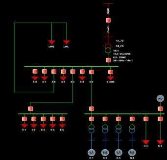
7 3. FUNCTIONS 3.1 Topological Processor The topological processor travels along the power grid, starting from the power supply points, to the load points. In its path, it can propagate topological data such as the state of energy (energized, de-energized, parallel, undefined, grounded etc.), voltage level, color (by state, voltage level or supply point), etc. The topological processor is used internally in all the analysis and optimization applications. DMS uses an extremely fast tree path algorithm with instant response (more than 100,000 nodes are processed in less than 0.9 seconds). This is because in the network modeling used each element knows to which other elements it is connected, thus avoiding expensive and unnecessary searches. 3.2 Power Flow Figure 1. Example of an Electric network differentiating the voltage levels by colors The Power Floe calculates the node voltages, power and current flows in lines and transformers, knowing the load data and injections in to the system. This is done with the data obtained by meters in field that report to the SCADA System, so that the operator can know the state of the system at any time, and make simulations for short -term planning.

8 As for usage, if the user wants to know a voltage in a node, he must click on it and the program will show the corresponding value on the screen (see Figure 2); likewise for transmission lines and/or transformers to show power and currents flows. If the user carries out operations such as opening or closing a breaker, raising or lowering a tap of a transformer or the excitation of a generator (changing data of loads, lines etc.), the displayed values change immediately according to the electrical impact of the operation. It is also possible to retain voltage data of the power system, using a specific option of the program to compare new voltage data after some maneuver h as been performed. In addition, DMS allows to carry out comparisons thro ugh the use of several windows. W ith this option the user is able to observe two states of the power system simultaneously. DMS has three methods of load flow: ZBus Load Flow, Newton-Raphson Complete and Newton-Raphson decoupled. The user can select the one that fits better with his working way. It also allows to have different models of load: Constant Power, Constant Impedance, Exponential Model and ZIEP Model. In the ZIEP model, each load can have individual modeling. Figure 2. Example of visualization of node voltages, currents and powers in an electric network.
. The short circuit analysis is used to adjust the protections of the system.")
9 3.3 Short Circuit Analysis It allows to know the levels of short circuit in specific points and the contributions of the elements to the short. The different types of fault can be simulated (three-phase, singlephase, two-phase, and between phases). The short circuit analysis is used to adjust the protections of the system. When carrying out fault simulation at any point in the network, selected by the user, immediately all the electrical variables of the different elements of the system are calculated. The user can view, by clicking on any item, their data in the fault state, such as short circuit inputs, fault currents and fault voltages. In addition, it is possible to simulate all the fault cases assuming a fault impedance. Figure 3. Example of the display of the fault in a bus 3.4 Protection Coordination The coordination of protection s module allows to use the results of the short circuit analysis to simulate the operation of the system relays, and thus adjust and coordinate the protection system Energy Computer Systems S.A.S. 10

10 Figure 4. Example of the coordination of protection in a branch of an electric network DMS includes libraries where a collection of protection relays with their respective technical and operative characteristics are found, these characteristics can be visualized and modified to adapt to the requirements of the power system. DMS presents a window for visualization and manipulation of operation curves of relays. This tool supports the optimum coordination, since the made adjustments w ill be reflected in the relay settings in the power system. Another way to achieve the adjustment and coordination of protections, is to use the Automatic Coordination option in which DMS automatically adjusts the relays and their different parameters (tap, time dial, etc.) to achieve optimum coordination of protections in the system. To do this, the coordination criteria are introduced, such as backup time between consecutive relays, percentage of load flow at which the relays would operate, percentage of the fault at which instantaneous relays would operate, and so on. The program autonomously simulates faults throughout the system and adjusts the parameters of the relays by an optimization algorithm. Once the automatic module has finished, the user can verify, through simulations, the achieved coordination and customize it with specific changes, in order to get as close as possible to an ideal coordination. 11

11 3.5 Reactive Control The aim of reactive control is to maintain the voltages of the power system nodes within acceptable levels, so that there are no over -voltages or under-voltages while the losses are minimized. Reactive control is carried out by adjusting optimum operating points, by moving tap changers from the power transformers, and by connecting or disconnecting capacitor banks. DMS uses a genetic algorithm that can be parameterized to determine the positions of the taps and the capacitor s to be connected or disconnected. The number of generations and the size of the population can be parameterized, as well as the lower and upper limits of voltage. The solutions are tested using the load flow, as well as the calculation of the objective function. 3.6 Optimal Load Flow Figure 5. Example of the reactive control The optimal load flow is a variation of the traditional load flow, where the objective is to find the operating conditions that allow a minimum operation cost, taking into account the cost of generation and t he cost of energy losses. In the optimal flow of DMS, the lower and upper voltage limits are also taken into account. A genetic algorithm that can be parameterized is used, where the user can establish the cost of losses, the number of generations, the size of the population and the voltage limits. To use the optimal flow, a cost of function is assigned to each generator, and its operational limits are parameterized (minimum active power generated, maximum active 12

12 power generated, minimum reactive power generated, maximum reactive power generated). The final result of the optimization are the power dispatches of each generator. 3.7 Contingency Analysis Figure 6. Example of Optimal Load Flow The power systems are operated in such a way that no overload or any statistically possible contingency occurs in real time. A contingency is a situation where one or more elements of the network are lost, for example the opening of a line or transformer. These contingencies are analyzed to determine the operating solutions that generate the least impact on the system (avoiding overloads and loss of stability). Using fault probabilities per element, DMS simulates the output of an element (line, transformer or generator) through a generator of random numbers, taking the necessary measures so that the load flow converges with the voltage within the limits allowed in contingency and without overloading the elements of the network. Among the remedial measures taken by the contingency analysis module are load shedding, load transfers and connection of backup elements if there are any available. 3.8 Load Forecast It consists of the prediction of the hourly load of energy demand of the system in the short term. It is based on the load history, weather conditions, day of the week and seasonal data. 13
13 DMS uses neural networks, which are trained with historical readings data. The reading information is classified on typical days (Ordinary, Festive, Saturday, etc.) in such a way that there is a neural network for each typical day. The neural network returns a projected power value receiving as input the hour data. 3.9 State Estimation The state estimation provides an optimal estimate of the state of the system based on available measurements and the assumed network model. The state estimation is composed of the following functions: Data Acquisition: The different measurements are obtained through the SCADA system. Processing of the network topology : Gets the state of the breakers and sets up the system diagram. Observability analysis: Determines if a state estimation can be obtained for the whole system using the set of available measurement s. State Estimation Solution: Determines an optimal state estimation of the system, which corresponds to the complex voltages at the nodes of the whole system. This estimate is based on the network model and available measures. Processing of erroneous data: Detects the existence of errors in the systems measurements. Identification of the network model : Estimates the parameters of the network and detects errors in the configuration of the network identifying erroneous states of the breakers. 14

14 Figure 7. Example of the state estimation and options of the connection of SCADA to DMS 3.10 FLISR- Fault Location, Isolation and Service Restoration Reducing the interruption time to customers in the distribution network has always been a goal for the power distributor s. The integrated SCADA EMS/DMS OMS (also recently named ADMS-Advanced Distribution Management Systems) systems automate the network to achieve it. These are the systems responsible for minimizing the interruption time identifying precisely the fault localization and re-energizing areas that are not in fault condition. For this reason, the algorithms of localization, isolation and restoration of the service are an important part of ADMS. FLISR is operated and visualized on the OMS. In Spin s solution a centralized algorithm that works in the control center is used, which works with the opening (interruptions) information that arrives from SCADA. When opening of a circuit or of a recloser happens, the FLISR algorithm is activated, which triggers the following steps: Fault Location Obtaining the Fault Data: Fault current data is captured for all three phases. The last read voltage is used as the pre-fault voltage. If no data is available on the SCADA (not all 15
15 protection devices have this functionality), the operator can enter the estimated current data. Identification of the Fault Type: The currents are analyzed using fuzzy logic to classify the fault into one of four types: three -phase fault, single-phase fault, biphasic fault and between phases. Depending on the type of the fault, the current fault data is converted into fault impedance. Network route: The network is traversed from the opening point until the fault impedance is found. There can be the case to find multiple possible points. Fault Grouping in Clusters: In the case that several possible fault points are identified, historical faults are grouped in to clusters. To each cluster a fault probability is given. The user must confirm the point of failure. Fault Isolation Detection of Power Points: To detect the power supply points of the fault, the network is traversed from the fault location until protection devices are found. Ideally, the system should have devices with remote control. You can restrict the protection devices available in the parameterization of the algorithm. Fault Isolation: Consists of sending opening commands to all the protection devices that supply, or could supply, into the fault. It can be parameterized to be performed automatically or manually with the authorization of the operator, or just as a suggestion. Service Restoration Detection of Possible Connection Points: Once the fault is isolated, the disconnected load is broken up into islands. For each island, the possible connection points are identified by going over the network fro m the opened points, when the fault is isolated. Detection of the Optimum Connection Point: For each possible connection point, of each island, an optimum connection point is determined. To do this, the load flows are simulated, connecting the island to th e connection point. The load flow determines: possible overloads, power losses, and maximum voltage drop (voltage). The optimal point depends on what is desired to optimize (losses, voltage, overloads). It is possible to parameterize the optimization criterion. Restore of the Normal Condition of Operation Once the fault is repaired, the system can be operated under normal conditions. To do this, all the operations carried out are saved and executed in the reverse order of their original execution. 16
16 3.11 Operator Training System OTS OTS or Operator Training System is the DMS function that allows to train SCADA personal in an operative environment with real conditions, but in a simulated way. In OTS the real network is replaced, where situations that happen in reality are re produced, with the security that the student is not going to make operations over the real electrical infrastructure. OTS is a tool that allows the instructor to design scenarios with programmed event sequences, which can be executed automatically. The instructor also can generate improvised incidences manually. The types of occurrence that are included are: opening/closing a breaker, tap change, load input/output, motor input/output, generation input/output, capacitor bank input/output, and fault occurrence. OTS has a two -way communication with the SCADA. All the variables of operable elements (such as breakers) in SCADA must reach OTS. Equally, OTS feeds back SCADA with data of electrical type, simulating the operation of the real network. The variables sent in this mode are: Active and Reactive Power of the loads. Breakers Position. Position of Transformer Taps. Voltage on the Controlled Voltage and Float Nodes. Generated Power by Generators. Active and Reactive Power consumed by Motors. Reactives Generated by Capacitors Voltages (value and angle) on the PQ Nodes. Currents and Powers on Lines. Currents and Powers on Transformers. Generated Active and Reactive Power by Float Nodes. Fault Currents and Voltages. In both ways, the operator can send commands from SCADA, which affect the DMS simulation and feed back the SCADA system. 17
17 The commands that can be sent from SCADA to DMS are: Breakers Operation Change of transformers taps. Change of dispatches in generators Data of Simulations of operation of the protection coordination system (Relay data) 18
Solutions for transmission network management
 EM SG SOLutions Solutions for transmission network management Energy Management Smart Grid Solutions Solutions for Transmission Network Management Overview Operator Training Simulator Blackout Prevention
Real-time Power System Operation. Energy Management Systems. Introduction
 1 Real-time Power System Operation Energy Management Systems Introduction The time frame for Power Systems Operation varies from a few seconds to a week. To assist with the operation of the system, modern
HIGH LEVEL REQUIREMENTS OF FAST SIMULATION AND MODELLING SUITE OF TOOLS FOR FUTURE SELF-HEALING DISTRIBUTION POWER SYSTEM
 HIGH LEVEL REQUIREMENTS OF FAST SIMULATION AND MODELLING SUITE OF TOOLS FOR FUTURE SELF-HEALING DISTRIBUTION POWER SYSTEM A. Valenti* I Bel ** S. Lee *EDF **EPRI E2I ConEdison France USA USA arnaud.valenti@edf.fr
EMS-LECTURE 2: WORKING OF EMS
 EMS-LECTURE 2: WORKING OF EMS Introduction: Energy Management systems consists of several applications programs which are used by the operator in a control centre for effective decision making in the operation
Chapter 2 State Estimation and Visualization
 Chapter 2 State Estimation and Visualization One obvious application of GPS-synchronized measurements is the dynamic monitoring of the operating conditions of the system or the dynamic state estimation
SurvalentONE Distribution Management System
 SurvalentONE Distribution Management System Analyze & Optimize Critical Grid Functions for Advanced System Monitoring & Control SurvalentONE ADMS The SurvalentONE ADMS platform is a fully integrated SCADA,
SCADA Training - T&D Automation
 SCADA Training - T&D Automation Contact us Today for a FREE quotation to deliver this course at your company?s location. https://www.electricityforum.com/onsite-training-rfq This course covers all the
Approval...6. Current Revision...7. Introduction... 8 About PJM Manuals... 8 About This Manual... 8 Using This Manual...9
 PJM Manual 07: PJM Protection Standards Revision: 3 Effective Date: May 24, 2018 Prepared by System Planning Division Transmission Planning Department PJM 2018 Table of Contents Table of Contents Approval...6
USE CASE 14 CONTROLLED ISLANDING
 I USE CASE 14 CONTROLLED ISLANDING Use Case Title Centralized application separates grid into islands to prevent blackout Use Case Summary Controlled islanding is a method that can significantly improve
Sacramen Sacr t amen o t Municipal Utility Dis t Dis rict t SMUD May Ma 10,
 Sacramento Municipal Utility District SMUD May 10, 2010 1 SMUD Facts and Figures 900 Sq. Miles Service Area 585,500 Customers 1.4 million Area Population 10 Bulk Substations 473 Miles of Transmission Lines
Substation SCADA Monitoring
 Substation SCADA Monitoring Contact us Today for a FREE quotation to deliver this course at your company?s location. https://www.electricityforum.com/onsite-training-rfq Substations are a critical component
Flexible High-Speed Load Shedding Using a Crosspoint Switch
 Flexible High-Speed Load Shedding Using a Crosspoint Switch Will Allen and Tony Lee Schweitzer Engineering Laboratories, Inc. Published in Wide-Area Protection and Control Systems: A Collection of Technical
Generation, Transmission, and End User Facilities
 Procedures for Interconnection of Generation, Transmission, and End User To the Grand River Dam Authority Transmission System Table of Contents GRDA/SPP Interaction... 3 Standards... 3 Generation... 3
p. 1 p. 9 p. 26 p. 56 p. 62 p. 68
 The Challenges and Opportunities Faced by Utilities using Modern Protection and Control Systems - Paper Unavailable Trends in Protection and Substation Automation Systems and Feed-backs from CIGRE Activities
Load Flow Analysis. I Objectives
 EE342 Electrical Power Lab Experiment PS3 Load Flow Analysis I Objectives To demonstrate load flow concepts. To study system performance under different operating conditions. To experience the real feel
POWER SYSTEM SECURITY CONCEPTS
 POWER SYSTEM SECURITY CONCEPTS 1.1 INTRODUCTION The Power System needs to be operationally secure, i.e. with minimal probability of blackout and equipment damage. An important component of power system
ELG4125: System Protection
 ELG4125: System Protection System Protection Any power system is prone to 'faults', (also called short-circuits), which occur mostly as a result of insulation failure and sometimes due to external causes.
Evolution of Control for the Power Grid
 Evolution of Control for the Power Grid Anjan Bose Washington State University Pullman, WA, USA PaiFest In Honor of Prof. M. A. Pai Urbana-Champaign, IL October 15, 2015 The Past (before 1960s) Hard
What You Should Know About Communication Systems: Business Strategies and Options
 Doug Voda, PPMV Global Segment Leader for Smart Grid February 2015 NRECA TechAdvantage What You Should Know About Communication Systems: Business Strategies and Options The visionary Smart Grid Five Pillars
Smart Distribution Technology
 Smart Distribution Technology Presentation Agenda Alabama Power Company, A Southern Company Distribution Automation Supervisory Control And Data Acquisition (SCADA) Multiple Address System (MAS) communications
System Protection and Control Subcommittee
 Power Plant and Transmission System Protection Coordination GSU Phase Overcurrent (51T), GSU Ground Overcurrent (51TG), and Breaker Failure (50BF) Protection System Protection and Control Subcommittee
Demonstration Test Bed for Advanced Control Systems
 Demonstration Test Bed for Advanced Control Systems Christopher R Clarke Senior Engineer SCE Advanced Technology June 22, 2016 1 Advanced Distribution Control Systems Introduction of customer adoption
DISRIBUTED AUTOMATION FOR BACK-FEED NETWORK POWER RESTORATION
 DISRIBUTED AUTOMATION FOR BACK-FEED NETWORK POWER RESTORATION Fahrudin Mekic Zhenyuan Wang Vaibhav Donde Fang Yang James Stoupis ABB Inc. USA ABB Inc. USA ABB Inc. USA ABB Inc. USA ABB Inc. USA fahrudin.mekic@us.abb.com
Fortum SGEM Program Presentation of ongoing research activities
 Fortum SGEM Program Presentation of ongoing research activities MV and LV Network Automation Solutions in EU Benchmarking Research 1 Existing Distribution Grid Little change in the past few decades Mostly
DTRV-EP. COMPLEX DIGITAL PROTECTION FOR 120 kv / MEDIUM VOLTAGE TRANSFORMERS. Application field
 DTRV-EP COMPLEX DIGITAL PROTECTION FOR 120 kv / MEDIUM VOLTAGE TRANSFORMERS Application field The DTRV type of complex transformer protection is designed to protect 120 kv / medium voltage transformers,
Centralized & Distributed Intelligence applied to Distribution Automation
 Centralized & Distributed Intelligence applied to Distribution Automation Table of Contents Automated Feeder restoration, put to the test Centralized Control and Distributed intelligence Distributed intelligence
Volt/VAR Control Options and How to Leverage AMI Data
 By Tom Helmer, Executive Consultant and Joseph Sottnik, P.E., Project Manager, Black & Veatch Published in the August 2012 issue of PowerGrid International Energy efficiency and operational optimization
Small Generator Interconnection System Impact Study Report. Completed For Q0047
 Small Generator Interconnection Completed For Q0047 Proposed Interconnection PacifiCorp s Existing Goshen Rigby 69 kv Line March 7, 2005 1.0 Description of the Generation Facility Q0047 ( Interconnection
PG&E Transmission Interconnection Handbook
 Table of Contents TABLE OF CONTENTS... 1 UPDATE HISTORY... UP-1 INTRODUCTION... IN-1 I-1. PURPOSE... IN-1 I-2. INTRODUCTORY DEFINITIONS... IN-1 I-3. HANDBOOK APPLICABILITY... IN-2 I-3.1. New Load, New
IMS INTERFACE MARKET PROCEDURE NETWORK OPERATORS AND AEMO
 IMS INTERFACE MARKET PROCEDURE NETWORK OPERATORS AND AEMO PREPARED BY: System Management (WA) DOCUMENT REF: SO_OP_WA_3805 VERSION: 1.0 EFFECTIVE DATE: 13/10/2017 STATUS: FINAL Approved for distribution
Power System Network Simulator (PSNsim)
") The PSNsim is hardware simulator that simulates all parts of power system from generation to utilization. The PSNsim is a scaled down model of the real power system that provides an experimental environment
The PSNsim is hardware simulator that simulates all parts of power system from generation to utilization. The PSNsim is a scaled down model of the real power system that provides an experimental environment
Road Map to Grid Modernization
 Road Map to Grid Modernization APIC, University of Alberta May 5 th, 2016 Presenter: Chris Chapelsky, MSc., P.Eng. Operations 1 Engineer About EPCOR Water & Power Transmission & Distribution in Edmonton
Modular Smart Grid Power Systems Simulators (Utilities)
") Modular Smart Grid Power Systems Simulators (Utilities) AEL-MPSS SCADA Key features: Several Utilities and Final User options. Modular and scalable applications (from simple to advance complexity). Scalable
Modular Smart Grid Power Systems Simulators (Utilities) AEL-MPSS SCADA Key features: Several Utilities and Final User options. Modular and scalable applications (from simple to advance complexity). Scalable
Maximizing protection coordination with self-healing technology
 Supersedes December 2011 Daniel P. Roth, Distribution Automation Technical Manager, Eaton s Cooper Power Systems Abstract Much of the Smart Grid initiative includes the installation of new recloser and
MAHALAKSHMI ENGINEERING COLLEGE TIRUCHIRAPALLI EE-2401 POWER SYSTEM OPERATION AND CONTROL UNIT-III REACTIVE POWER VOLTAGE CONTROL
 MAHALAKSHMI ENGINEERING COLLEGE TIRUCHIRAPALLI 621213 EE-2401 POWER SYSTEM OPERATION AND CONTROL UNIT-III REACTIVE POWER VOLTAGE CONTROL TWO MARKS: 1. What are the sources of reactive power? How it is
Shabnam Rukhsar Electrical Engineering Department, Anjuman College of Engineering and Technology.India
 SCADA in Transmission Line Shabnam Rukhsar Electrical Engineering Department, Anjuman College of Engineering and Technology.India ABSTRACT: Transmission line equivalent circuit parameters are often 25%
High-Reliability Fault-Clearing System solution. Application Guide. Outdoor Distribution (15.5 kv through 38 kv) S&C ELECTRIC COMPANY
 S&C ELECTRIC COMPANY") S&C Remote Supervisory V ista Outdoor Distribution (15.5 kv through 38 kv) Electric utility customers are increasingly concerned about the frequency and duration of outages they are experiencing, and are
S&C Remote Supervisory V ista Outdoor Distribution (15.5 kv through 38 kv) Electric utility customers are increasingly concerned about the frequency and duration of outages they are experiencing, and are
ADVANCED. Protection Co-ordination. H.H. Sheik Sultan Tower (0) Floor Corniche Street Abu Dhabi U.A.E
 Floor Corniche Street Abu Dhabi U.A.E") ADVANCED Protection Co-ordination H.H. Sheik Sultan Tower (0) Floor Corniche Street Abu Dhabi U.A.E www.ictd.ae ictd@ictd.ae Course Introduction: Distribution Networks are designed to serve loads in a
ADVANCED Protection Co-ordination H.H. Sheik Sultan Tower (0) Floor Corniche Street Abu Dhabi U.A.E www.ictd.ae ictd@ictd.ae Course Introduction: Distribution Networks are designed to serve loads in a
Substation Automation Products. Line differential protection RED670 Relion 670 series
 Substation Automation Products Line differential protection RED670 Relion 670 series For maximum reliability of your power system The RED670 IED (Intelligent Electronic Device) is designed for protection,
Advanced Protection and Control Technologies for T&D Grid Modernization
 Advanced Protection and Control Technologies for T&D Grid Modernization i-pcgrid Workshop San Francisco, CA March 31, 2016 Jeff Shiles, Principal Manager Protection & Automation Engineering Southern California
POWER FLOW ANALYSIS AND PROTECTION COORDINATION OF REAL TIME SYSTEM
 POWER FLOW ANALYSIS AND PROTECTION COORDINATION OF REAL TIME SYSTEM Thanigaivel M PG Scholar Power Systems Engineering Sri Muthukumaran Institute of Technology Chennai, India Azeezur Rahman A Assistant
A Data Approach to Advanced Distribution Management Systems. L. WILKE, B. WALL POWER Engineers USA
 21, rue d Artois, F-75008 PARIS CIGRE US National Committee http : //www.cigre.org 2017 Grid of the Future Symposium A Data Approach to Advanced Distribution Management Systems L. WILKE, B. WALL POWER
Substation Automation Products. Bay control REC670/650 Relion 670 and 650 series
 Substation Automation Products Bay control REC670/650 Relion 670 and 650 series For optimized control and reliable operation of your switchyard The REC670 and REC650 Bay control IEDs (Intelligent Electronic
SCADA and Central Applications An introduction
 SCADA and Central Applications An introduction Course map Outline of the lecture Power System Operation - Centralised Control Applications SCADA - SCADA architecture & Components - SCADA system functions
Process and Power Control
 Process and Power Control Insert Photo Here Sergio Gama Rockwell Automation Rockwell Automation Process Solutions User Group (PSUG) November 14-15, 2011 Chicago, IL McCormick Place West Copyright 2011
PUBLIC SERVICE OF NEW HAMPSHIRE. Technical Requirements for Non Utility Generation Interconnecting to the PSNH Distribution System
 PUBLIC SERVICE OF NEW HAMPSHIRE Technical Requirements for Non Utility Generation Interconnecting to the PSNH Distribution System September 2013 1.0 Purpose of this document Public Service of New Hampshire
Blackout 101. Dr. B. Don Russell Texas A&M University. Dr. Bruce Wollenberg University of Minnesota. Mr. John McDonald KEMA, Inc.
 Blackout 101 Dr. B. Don Russell Texas A&M University Dr. Bruce Wollenberg University of Minnesota Mr. John McDonald KEMA, Inc. Dr. Pete Sauer University of Illinois at Urbana-Champaign An Electric Power
Automation of Distribution Grid with FLISR using ZigBee Communication
 Automation of Distribution Grid with FLISR using ZigBee Communication 1 Ajinkya Shirdhankar, 2 Digambar Ahire, 3 B. S. Kunure, 4 Asmita Bote Department of Electrical Engineering, ZCOER, Pune, India Abstract
Application Techniques CENTERLINE 2100 Motor Control Centers
 POWER SYSTEM CONSIDERATIONS FOR PRODUCT SELECTION Application Techniques CENTERLINE 2100 Motor Control Centers Power System Considerations for Product Selection i Power System Considerations for Product
Substation Automation Products. Generator protection REG670/650 Relion 670 and 650 series
 Substation Automation Products Generator protection REG670/650 Relion 670 and 650 series A new protection standard for your valuable assets Based on ABB s extensive experience, REG670 and REG650 IEDs (Intelligent
PRC Coordination of Protection Systems for Performance During Faults
 PRC-027-1 Coordination of Protection Systems for Performance During Faults A. Introduction 1. Title: Coordination of Protection Systems for Performance During Faults 2. Number: PRC-027-1 3. Purpose: To
IMPROVING POWER SYSTEM RELIABILITY USING MULTIFUNCTION PROTECTIVE RELAYS
 IMPROVING POWER SYSTEM RELIABILITY USING MULTIFUNCTION PROTECTIVE RELAYS Armando Guzmán Schweitzer Engineering Laboratories, Inc. Pullman, WA 99163 A reliable power system maintains frequency and voltage
PROTECTION, AUTOMATION & CONTROL
 PROTECTION, AUTOMATION & CONTROL 1. DTIVA The members of the DTIVA product line are configured to protect and control the elements of not solidly grounded radial networks. Here the application of Petersen
SPECIFIC INTERCONNECTION PROTECTION REQUIREMENTS... 5
 Central Hudson Gas & Electric Corporation (CHG&E) Interconnection Protection Requirements for Distributed Generators of Greater than 300 kva Connected in Parallel with the CHG&E Electrical Delivery System
The various functions of an energy control center can be enumerated as under: 1. Load forecasting 6. Automatic generation control
 ENERGY CONTROL CENTERS To generated, Transmission and Distribution system, Number of customers and Total investment. Installed capacity in India exceeds 206 GW with annual energy generated energy exceeding
ENERGY MANAGEMENT SYSTEM. ABB Ability Network Manager EMS Operational confidence.
 ENERGY MANAGEMENT SYSTEM ABB Ability Network Manager EMS Operational confidence. 2 ABB ABILITY NETWORK MANAGER EMS ABB Ability Network Manager Energy Management System The ever-increasing demand for power
SE Engineering, PC strives to be a leader in the power system engineering field by providing our customers with the highest level of quality,
 SE Engineering, PC strives to be a leader in the power system engineering field by providing our customers with the highest level of quality, integrity, and innovation. Our mission is to offer the safest,
Karl Iliev, San Diego Gas & Electric Company
 INTEGRATING DER THROUGH DISTRIBUTION SYNCROPHASORS Karl Iliev, San Diego Gas & Electric Company 2002 San Diego Gas and Electric Co. and Southern California Gas Company. All copyright and trademark rights
USE CASE 13 ADAPTIVE TRANSMISSION LINE PROTECTION
 H USE CASE 13 ADAPTIVE TRANSMISSION LINE PROTECTION Use Case Title Adaptive Transmission Line Protection Use Case Summary The requirements for improvement in the performance of protection relays under
Lecture 5 Substation Automation Systems. Course map
 Lecture 5 Substation Automation Systems 1 Course map 2 1 Contents of the Lecture Part 1 Substation Automation Components Substation Automation Functions Communication within the Substation (Intro) Part
IntelliTeam II Automatic Restoration System
 No system is too complex to automate with... IntelliTeam II Automatic Restoration System Introduced in 1997, the IntelliTeam Automatic Restoration System was the first product of its kind. Using peer-to-peer
Exercise 2. Single Bus Scheme EXERCISE OBJECTIVE DISCUSSION OUTLINE. The single bus scheme DISCUSSION
 Exercise 2 Single Bus Scheme EXERCISE OBJECTIVE When you have completed this exercise, you will be familiar with electric power substations using the single bus scheme with bus section circuit breakers.
Power System Enterprise Solution
 Power System Enterprise Solution ETAP is the most comprehensive analysis platform for the design, simulation, operation, control, optimization, and automation of generation, transmission, distribution,
Substation Automation Products. Transformer protection RET670/650 Relion 670 and 650 series
 Substation Automation Products Transformer protection RET670/650 Relion 670 and 650 series For reliable protection and control of all types of power transformers and reactors The RET670/650 IEDs (Intelligent
Advanced Line Differential Protection, Automation, and Control System. Combine subcycle line protection with traveling-wave fault locating
 Advanced Line Differential Protection, Automation, and Control System Combine subcycle line protection with traveling-wave fault locating Subcycle differential and distance protection minimizes damage
Glencoe Light and Power
 Glencoe Light and Power REQUIREMENTS FOR GENERATION, TRANSMISSION, AND END-USER FACILITY INTERCONNECTIONS 1 Table of Contents Page I. INTRODUCTION...5 A. Authority... 5 B. Objectives...5 C. Interconnection
MONTANA-DAKOTA UTILITIES REQUIREMENTS FOR GENERATION, TRANSMISSION, AND END-USER FACILITY INTERCONNECTIONS
 MONTANA-DAKOTA UTILITIES REQUIREMENTS FOR GENERATION, TRANSMISSION, AND END-USER FACILITY INTERCONNECTIONS Table of Contents I. Introduction... 5 A. Authority... 5 B. Objectives... 5 C. Interconnection
Standard Development Timeline
 Standard Development Timeline This section is maintained by the drafting team during the development of the standard and will be removed when the standard becomes effective. Description of Current Draft
AUTOMATION OF POWER DISTRIBUTION USING SCADA
 1 2 ABSTRACT In every substation certain measurements, supervision, control, operation and protection functions are necessary. Traditionally these functions were performed manually by system operator from
Lecture 6 Substation Automation Systems
 Lecture 6 Substation Automation Systems 1 Course map 2 Contents of the Lecture Part 1 Substation Automation Components & Architectures Substation Automation Functions Communication within the Substation
EE076: Load Flow Analysis, Short Circuit Calculations & Protection Coordination
 EE076: Load Flow Analysis, Short Circuit Calculations & Protection Coordination EE076 Rev.001 CMCT COURSE OUTLINE Page 1 of 6 Training Description: This course provides a comprehensive review of the fundamental
COGENERATION INTERCONNECTION REQUIREMENTS. Parallel Operation of Connecting Parties Generation
 COGENERATION INTERCONNECTION REQUIREMENTS Parallel Operation of Connecting Parties Generation Cogeneration Interconnection Requirements (ID 195440).docx 1 (This page left blank intentionally) Cogeneration
Automation Services and Solutions
 Automation Services and Solutions Automate substation data acquisition and control to improve performance Maintain uninterrupted power services with proactive grid monitoring and controlling features.
Automation in Large Urban Power Distribution System. Dr. K Rajamani CENTRAL TECHNICAL SERVICES, RELIANCE ENERGY LIMITED, MUMBAI
 Automation in Large Urban Power Distribution System Dr. K Rajamani CENTRAL TECHNICAL SERVICES, RELIANCE ENERGY LIMITED, MUMBAI Need for Automation and Current trends Automation Systems and Functionality
Microgrids: Building Blocks of the Smart Grid Adaptive Protection Schemes for Microgrids
 Enrico Ragaini (ABB Low Voltage Products), Alexandre Oudalov (ABB Corporate Research), ISGT Europe 2012, Berlin Microgrids: Building Blocks of the Smart Grid Adaptive Protection Schemes for Microgrids
ActionWise. Software SCADA/ADMS. Configuration and Operation Manual. Version 2 Rev 2. Spin Engenharia de Automação Ltda. Brasilia, March 2017
 ActionWise Software SCADA/ADMS Configuration and Operation Manual Version 2 Rev 2 Spin Engenharia de Automação Ltda. Brasilia, March 2017 SPIN Engenharia de Automação Ltda. SCLN 212 Bloc D - Room 101 PO
NETWORK CONTROL SOLUTIONS BASED ON AN EDGE COMPUTING ARCHITECTURE Open Field Message Bus (FMB) Brussels (Belgium) December 2015
 Brussels (Belgium) December 2015") NETWORK CONTROL SOLUTIONS BASED ON AN EDGE COMPUTING ARCHITECTURE Open Field Message Bus (FMB) Brussels (Belgium) December 2015 INDEX 01 Utilities Trends: Towards a Smart Grid 02 Edge Computing Architectures
NETWORK CONTROL SOLUTIONS BASED ON AN EDGE COMPUTING ARCHITECTURE Open Field Message Bus (FMB) Brussels (Belgium) December 2015 INDEX 01 Utilities Trends: Towards a Smart Grid 02 Edge Computing Architectures
SEL Real-Time Automation Controller (RTAC)
") SEL Real-Time Automation Controller (RTAC) Product Family Rugged, deterministic, and reliable automation controllers for any environment 1 ms deterministic processing intervals support critical protection
SEL Real-Time Automation Controller (RTAC) Product Family Rugged, deterministic, and reliable automation controllers for any environment 1 ms deterministic processing intervals support critical protection
BC Hydro s Voltage and VAR Optimization Program IEEE PES JTCM VVC TF - 13 Jan 2010
 BC Hydro s Voltage and VAR Optimization Program IEEE PES JTCM VVC TF - 13 Jan 2010 Prepared by: Valentina Dabic P.Eng, Distribution Operations Planning Cheong Siew P.Eng, Smart Grid Development BC Hydro
Design of Coal Mine Power Supply Monitoring System
 2nd International Conference on Electronics, Network and Computer Engineering (ICENCE 2016) Design of Coal Mine Power Supply Monitoring System Lei Shi 1, Guo Jin 2 and Jun Xu 3 1 2 Department of electronic
CASE STUDY : Transient Stability Simulation Package
 CASE STUDY : Transient Stability Simulation Package CLIENT NAME : A major T&D solutions provider in the world END CUSTOMER : A public T&D utility in one of the SAARC nations PROJECT TITLE : Customized
Real Time Monitoring of
 Real Time Monitoring of Cascading Events Mladen Kezunovic Nan Zhang, Hongbiao Song Texas A&M University Tele-Seminar, March 28, 2006 Project Reports (S-19) M. Kezunovic, H. Song and N. Zhang, Detection,
IMS INTERFACE MARKET PROCEDURE NETWORK OPERATORS AND AEMO
 IMS INTERFACE MARKET PROCEDURE NETWORK OPERATORS AND AEMO PREPARED BY: System Management (WA) DOCUMENT REF: SO_OP_WA_3805 VERSION: 1.0 EFFECTIVE DATE: 13/10/2017 STATUS: DRAFT FOR CONSULTATION Approved
Bus Protection Application Challenges
 Bus Protection Application Challenges KN Dinesh Babu - Megger JC Theron, Lubomir Sevov GE Grid Solutions 2017 Texas A&M Protective Relay Conference Content Introduction Application Challenges Increase
PowerWorld s Experience Using Real-Time Power System Models
 PowerWorld s Experience Using Real-Time Power System Models Presented by: James Weber, Ph.D. Director of Software Development February 28, 2018 2001 South First Street Champaign, Illinois 61820 (217) 384-6330
Redundant Bus Protection Using High-Impedance Differential Relays. Josh LaBlanc
 Redundant Bus Protection Using High-Impedance Differential Relays Josh LaBlanc Purpose Discuss the configuration of the bus under study, and touch on the needs for redundant protection on the bus. Briefly
1 Description of Methodology for Volt / Var Optimization
 Methodology for Volt / Var Optimization on a Substation Basis May 13th, 2011 Version 1.7 1 Methodology for Volt / Var Optimization (VVO) on a Substation Basis This use case discusses how the utility will
Standard Development Timeline
 Standard Development Timeline This section is maintained by the drafting team during the development of the standard and will be removed when the standard becomes effective. Description of Current Draft
REAL-TIME MONITORING DATA SPECIFICATION
 REAL-TIME MONITORING DATA SPECIFICATION Version 1 December 9, 2016 Revision History Version Date Reviewer Revisions 1 11/1/16 Mansion Hudson Initial document 1 Contents 1. DOCUMENT REVIEW... 3 2. DEFINITIONS...
FAULT DETECTION ISOLATION AND RESTORATION ON THE FEEDER (FDIR): PICK YOUR TECHNOLOGY
: PICK YOUR TECHNOLOGY") FAULT DETECTION ISOLATION AND RESTORATION ON THE FEEDER (FDIR): PICK YOUR TECHNOLOGY Fahrudin Mekic Ken Alloway Cleber Angelo Robert Goodin ABB Inc. USA ABB Inc. USA ABB Inc. USA ABB Inc. USA fahrudin.mekic@us.abb.com.ken.alloway@us.abb.com
FAULT DETECTION ISOLATION AND RESTORATION ON THE FEEDER (FDIR): PICK YOUR TECHNOLOGY Fahrudin Mekic Ken Alloway Cleber Angelo Robert Goodin ABB Inc. USA ABB Inc. USA ABB Inc. USA ABB Inc. USA fahrudin.mekic@us.abb.com.ken.alloway@us.abb.com
It is the job of the protection system equipment to recognize and remove the fault.
 Protection 1 (read section 13.0 of text) 1.0 Introduction Faults do not occur that frequently 1/year/100 miles of transmission is typical. Distribution systems may see more than this. However, when they
This webinar brought to you by the Relion product family
 This webinar brought to you by the Relion product family Relion. Thinking beyond the box. Designed to seamlessly consolidate functions, Relion relays are smarter, more flexible and more adaptable. Easy
Automatic simulation of IED measurements for substation data integration studies
 1 Automatic simulation of IED measurements for substation data integration studies Y. Wu, Student Member, IEEE, and M. Kezunovic, Fellow, IEEE Abstract With the deregulation and restructuring of utility
MiCOM P124. Self and Dual Powered Overcurrent Relays. Protection Relays
 01 Self and Dual Powered Overcurrent Relays are numerical relays designed to offer complete overcurrent protection without requiring any external auxiliary supply. They can be applied to a wide variety
Advanced Protection and Control for a Power System Serving Industrial Customers
 Advanced Protection and Control for a Power System Serving Industrial Customers Marco F. Jorge Iberdrola Energía Monterrey David Sánchez, Héctor J. Altuve, and Jorge L. Soto Schweitzer Engineering Laboratories,
EPRI GIS Interest Group GIS Data Correction
 EPRI GIS Interest Group GIS Data Correction The Southern Company Serve 4.4 Million Retail Customers Generating Capacity : 42,000 MW 120,000 Square Miles Alabama Power Company Serves 1,431,334 Customers
Siemens AG I IA CE CP R&D-VI 4 WERNER-VON-SIEMENS-STRASSE AMBERG, GERMANY
 Issued to: Siemens AG I IA CE CP R&D-VI 4 WERNER-VON-SIEMENS-STRASSE 48 92220 AMBERG, GERMANY This is to certify that Auxiliary Devices representative samples of 3UF70 followed by 0 or 1 followed by 0
FCIs reduce fault-locating times and improve reliability metrics, especially the Customer Average Interruption Duration Index (CAIDI).
.") 1 Intelligent electronic devices (IEDs) are the preferred choice for modernizing the grid. Communication among networks of robust IEDs designed for protection, control, and monitoring (PCM) of the power
1 Intelligent electronic devices (IEDs) are the preferred choice for modernizing the grid. Communication among networks of robust IEDs designed for protection, control, and monitoring (PCM) of the power
INTERCONNECTION FACILITIES STUDY REPORT
 Interconnection Request No. TI-08-0312 INTERCONNECTION FACILITIES STUDY REPORT Prepared by Tri-State Generation and Transmission Association, Inc. 1 of 7 DISCLAIMER OF WARRANTIES AND LIMITATION OF LIABILITIES
LAB1 INTRODUCTION TO PSS/E EE461: POWER SYSTEMS COLORADO STATE UNIVERSITY
 LAB1 INTRODUCTION TO PSS/E EE461: POWER SYSTEMS COLORADO STATE UNIVERSITY PURPOSE: The purpose of this lab is to introduce PSS/E. This lab will introduce the following aspects of PSS/E: Introduction to