Brooks Models MT3809G Metal Tube Variable Area Flowmeters HART Handheld DD Installation & Operation Manual
|
|
|
- Bennett Green
- 6 years ago
- Views:
Transcription

1 Installation and Operation Manual Supplement Brooks Models MT3809G Metal Tube Variable Area Flowmeters HART Handheld DD Installation & Operation Manual
2 Installation and Operation Manual Supplement Essential Instructions Read before proceeding! Brooks Instrument designs, manufactures and tests its products to meet many national and international standards. These products must be properly installed, operated and maintained to ensure they continue to operate within their normal specifications. The following instructions must be adhered to and integrated into your safety program when installing, operating and maintaining Brooks Instrument products. To ensure proper performance, use qualified personnel to install, operate, update, program and maintain the product. Read all instructions prior to installing, operating and servicing the product. If this instruction manual is not the correct manual, please see back cover for local sales office contact information. Save this instruction manual for future reference. WARNING: Do not operate this instrument in excess of the specifications listed in the Instruction and Operation Manual. Failure to heed this warning can result in serious personal injury and / or damage to the equipment. If you do not understand any of the instructions, contact your Brooks Instrument representative for clarification. Follow all warnings, cautions and instructions marked on and supplied with the product. WARNING: Prior to installation ensure this instrument has the required approval ratings to meet local and national codes. Failure to heed this warning can result in serious personal injury and / or damage to the equipment. Install your equipment as specified in the installation instructions of the appropriate instruction manual and per applicable local and national codes. Connect all products to the proper electrical and pressure sources. Operation: (1) Slowly initiate flow into the system. Open process valves slowly to avoid flow surges. (2) Check for leaks around the flow meter inlet and outlet connections. If no leaks are present, bring the system up to the operating pressure. Please make sure that the process line pressure is removed prior to service. When replacement parts are required, ensure that qualified people use replacement parts specified by Brooks Instrument. Unauthorized parts and procedures can affect the product's performance and place the safe operation of your process at risk. Look-alike substitutions may result in fire, electrical hazards or improper operation. Ensure that all equipment doors are closed and protective covers are in place to prevent electrical shock and personal injury, except when maintenance is being performed by qualified persons. WARNING: For liquid flow devices, if the inlet and outlet valves adjacent to the devices are to be closed for any reason, the devices must be completely drained. Failure to do so may result in thermal expansion of the liquid that can rupture the device and may cause personal injury. European Pressure Equipment Directive (PED) All pressure equipment with an internal pressure greater than 0.5 bar (g) and a size larger than 25mm or 1" (inch) falls under the Pressure Equipment Directive (PED). The Specifications Section of this manual contains instructions related to the PED directive. Products described in this manual are in compliance with EN directive 97/23/EC. All Brooks Instrument Flowmeters fall under fluid group 1. Products larger than 25mm or 1" (inch) are in compliance with PED category I, II or III. Products of 25mm or 1" (inch) or smaller are Sound Engineering Practice (SEP). European Electromagnetic Compatibility (EMC) The Brooks Instrument (electric/electronic) equipment bearing the CE mark has been successfully tested to the regulations of the Electro Magnetic Compatibility (EMC directive 2004/108/EC). Special attention however is required when selecting the signal cable to be used with CE marked equipment. Quality of the signal cable, cable glands and connectors: Brooks Instrument supplies high quality cable(s) which meets the specifications for CE certification. If you provide your own signal cable you should use a cable which is overall completely screened with a 100% shield. D or Circular type connectors used should be shielded with a metal shield. If applicable, metal cable glands must be used providing cable screen clamping. The cable screen should be connected to the metal shell or gland and shielded at both ends over 360 Degrees. The shield should be terminated to an earth ground. Card Edge Connectors are standard non-metallic. The cables used must be screened with 100% shield to comply with CE certification. The shield should be terminated to an earth ground. For pin configuration : Please refer to the enclosed Instruction Manual. ESD (Electrostatic Discharge) CAUTION: This instrument contains electronic components that are susceptible to damage by static electricity. Proper handling procedures must be observed during the removal, installation or other handling of internal circuit boards or devices. Handling Procedure: 1. Power to unit must be removed. 2. Personnel must be grounded, via a wrist strap or other safe, suitable means before any printed circuit card or other internal device is installed, removed or adjusted. 3. Printed circuit cards must be transported in a conductive container. Boards must not be removed from protective enclosure until immediately before installation. Removed boards must immediately be placed in protective container for transport, storage or return to factory. Comments This instrument is not unique in its content of ESD (electrostatic discharge) sensitive components. Most modern electronic designs contain components that utilize metal oxide technology (NMOS, SMOS, etc.). Experience has proven that even small amounts of static electricity can damage or destroy these devices. Damaged components, even though they appear to function properly, exhibit early failure.
3 Installation and Operation Manual Supplement Dear Customer, We appreciate this opportunity to service your flow measurement and control requirements with a Brooks Instrument device. Every day, flow customers all over the world turn to Brooks Instrument for solutions to their gas and liquid low-flow applications. Brooks provides an array of flow measurement and control products for various industries from biopharmaceuticals, oil and gas, fuel cell research and chemicals, to medical devices, analytical instrumentation, semiconductor manufacturing, and more. The Brooks product you have just received is of the highest quality available, offering superior performance, reliability and value to the user. It is designed with the ever changing process conditions, accuracy requirements and hostile process environments in mind to provide you with a lifetime of dependable service. We recommend that you read this manual in its entirety. Should you require any additional information concerning Brooks products and services, please contact your local Brooks Sales and Service Office listed on the back cover of this manual or visit Yours sincerely, Brooks Instrument
4 Installation and Operation Manual Supplement THIS PAGE WAS INTENTIONALLY LEFT BLANK
5 Installation and Operation Manual Supplement Contents Paragraph Page Number Number Section 1 Introduction 1-1 Introduction Section 2 Installation 2-1 Installation Section 3 Operation 3-1 Start Communication Example - Access Process Variables: Example - Verify Tag Number: Example Verify Engineering Units and Range: Example - Set Low Alarm to Enable: Warranty, Local Sales/Service Contact Information... Back Cover i
6 Contents Installation and Operation Manual Supplement THIS PAGE WAS INTENTIONALLY LEFT BLANK ii
7 Installation and Operation Manual Supplement 1-1 Descripton Section 1 Introduction This document will describe the procedure for removing the existing 3809 Device description (DD) and installing the 3809G DD to the 475 HART Handheld (HH) using the SD card from the 475HH and the Easy Upgrade Utility program. Once installed access to the HART commands are available for Model 3809G. Equipment Needed: Computer with SD slot, 475 Handheld 1-1
8 Section 1 Introduction Installation and Operation Manual Supplement THIS PAGE WAS INTENTIONALLY LEFT BLANK 1-2
 b.")
9 Installation and Operation Manual Supplement 2-1 Installation Section 2 Installation This section contains the procedures for the installation of the 3809G DD. a. Copy supplied 3809G DD files to location: <Easy Upgrade Utility installation folder*>\mmi\field Communicator Easy Upgrade Utility 3.6\PC Database\DD\HART\en *note: the actual <Easy Upgrade Utility installation folder*> depends on original user installation of the Easy Upgrade Utility, e.g. C:\Program Files (x86) b. Remove SD card from 475HH c. Insert SD card into slot of computer d. Make sure the SD card is recognized (a new drive should be visible in Windows Explorer) e. Start Easy Upgrade Utility f. Press Connect (2. Connect Card Reader; Connection type Card Reader) 2-1
10 Section 2 Installation Installation and Operation Manual Supplement g.this screen will be visible when connected: h. Select "More Options" 2-2


11 Installation and Operation Manual Supplement Section 2 Installation i. Go to DDs option. j. On the card reader look for DD named Brooks Instrument 38xxVA Rev 1 DD1 k. Check the box and select "Remove" l. Check if DD Brooks Instrument 38xxVA Rev 1 DD1 was removed 2-3

 o.")
12 Section 2 Installation Installation and Operation Manual Supplement m. Go to the PC data base and look for DD: Brooks Instruments 38xxVA Rev 1 DD 2 n. Check the box and answer YES to the pending question (Check an untested package?) o. Press the arrows for transferring the DD to the card reader 2-4

13 Installation and Operation Manual Supplement Section 2 Installation p. Confirmation will be received when the new DD is installed on the card reader q. DD can be seen in the card reader location 2-5
14 Section 2 Installation Installation and Operation Manual Supplement r. Select Disconnect s. Remove the SD card from the computer t. Install the SD card into the 475HH u. HART communication with the model 3809G is now available 2-6


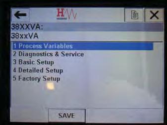
15 Installation and Operation Manual Supplement 3-1 Start Communcation Section 3 Operation a. Select CONT 3-1


16 Section 3 Operation Installation and Operation Manual Supplement 3-2 Example - Access Process Variables: 3-3 Example - Verify Tag Number: 3-2
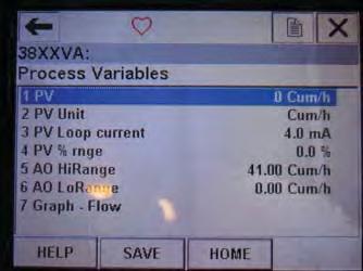
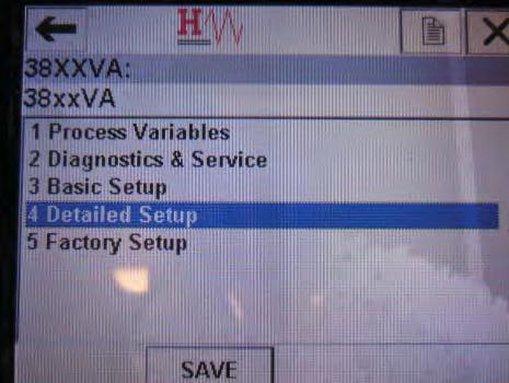
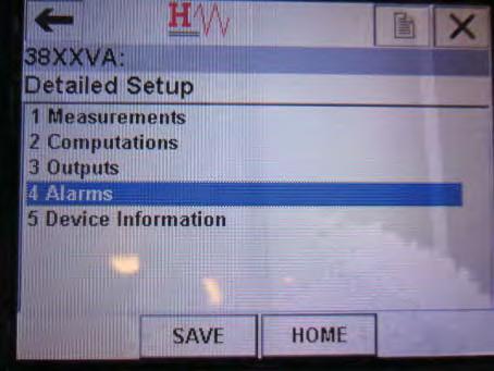
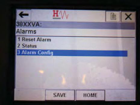
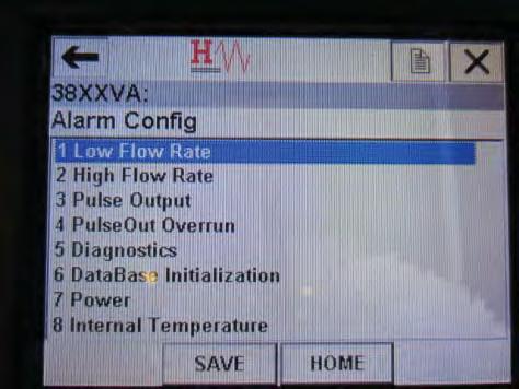
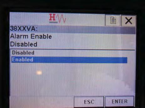
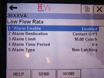
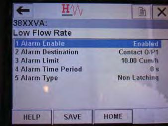
17 Installation and Operation Manual Supplement 3-4 Example - Verify Engineering Units and Range Section 3 Operation 3-5 Example - Set Low Alarm to Enable: 3-3
18 Installation and Operation Manual LIMITED WARRANTY Visit for the terms and conditions of our limited warranty. BROOKS SERVICE AND SUPPORT Brooks is committed to assuring all of our customers receive the ideal flow solution for their application, along with outstanding service and support to back it up. We operate first class repair facilities located around the world to provide rapid response and support. Each location utilizes primary standard calibration equipment to ensure accuracy and reliability for repairs and recalibration. The primary standard calibration equipment to calibrate our flow products is certified by our local Weights and Measures Authorities and traceable to the relevant International Standards. Visit to locate the service location nearest to you. START-UP SERVICE AND IN-SITU CALIBRATION Brooks Instrument can provide start-up service prior to operation when required. For some process applications, where ISO-9001 Quality Certification is important, it is mandatory to verify and/or (re)calibrate the products periodically. In many cases this service can be provided under in-situ conditions, and the results will be traceable to the relevant international quality standards. CUSTOMER SEMINARS AND TRAINING Brooks Instrument can provide customer seminars and dedicated training to engineers, end users and maintenance persons. Please contact your nearest sales representative for more details. HELP DESK In case you need technical assistance: Americas FLOW Europe +31 (0) Asia +81 (0) Due to Brooks Instrument's commitment to continuous improvement of our products, all specifications are subject to change without notice. TRADEMARKS Brooks... Brooks Instrument, LLC All other trademarks are the property of their respective owners. 2
Smart DDE Software. Smart DDE Software. for use with Brooks Digital Mass Flow Meter/Controller Series
 Installation and Operation Manual for use with Brooks Digital Mass Flow Meter/Controller Series Installation and Operation Manual Essential Instructions Read before proceeding! Brooks Instrument designs,
LR-056 Pressure Transducer Display
 Installation and Operation Manual Part Number: 541B171AAG Pressure Transducer Display Accurate, Miniature Plug-In Displays for Point-of-Use Pressure Monitoring LR-056 Pressure Transducer Display Installation
Gas and Liquid Mass Flow Secondary Electronics
 Installation and Operation Manual Gas and Liquid Mass Flow Secondary Electronics 5 Model 0251 Single Channel Secondary Electronics Model 0254 Table Top Four Channel Secondary Electronics Installation and
Quick Start Guide. Model 0260 Secondary Electronics
 Quick Start Guide Brooks Model 0260 Secondary Electronics 5 Quick Start Guide Dear Customer, The Brooks Smart Interface is a Microsoft Windows based software application that provides expanded control
Brooks Service Tool TM for QUANTIM Precision Mass Measurement and Control
 Installation and Operation Manual Precision Mass Measurement and Control www.brooksinstrument.com Installation and Operation Manual Essential Instructions Read this page before proceeding! Brooks Instrument
Quick Start Guide. X-SW-MultiFloConfig-QS-eng Part Number: 541B167AAG/B November, 2017
 Quick Start Guide Brooks MultiFlo TM Configur figurator for use with Brooks Instrument Thermal Mass Flow Devices 5 Quick Start Guide Dear Customer, The Brooks MultiFlo Configurator is a downloadable software
9861 Series. High Temperature Mass Flow Controllers/Meters. Overview. Product Description. Thermal Mass Flow
 DS-TMF-9861-Series-MFC-eng August, 2018 Data Sheet 9861 Series 9861 Series Mass Flow Controller/Meters Thermal Mass Flow High Temperature Mass Flow Controllers/Meters Overview Originally developed by Unit
Brooks Models SLA SLA7860 Mass Flow Controllers and Meters
 Data Sheet Brooks Models SLA7850 - SLA7860 Mass Flow Controllers and Meters General Features: 1.125" Mechanical Platform High performance coplanar valve All wetted surfaces are 32 Ra to maintain particle,
Brooks Expert Support Tool (BEST) Software for Brooks Devices (Version )
 Software for Brooks Devices (Version )") Installation and Operation Manual (BEST) Software for Brooks Devices (Version 4.4.0.0) Installation and Operation Manual Essential Instructions Read before proceeding! Brooks Instrument designs, manufactures
Installation and Operation Manual (BEST) Software for Brooks Devices (Version 4.4.0.0) Installation and Operation Manual Essential Instructions Read before proceeding! Brooks Instrument designs, manufactures
Quick Start Guide MHM CC-PBF-EN, Rev 1 April Emerson A0701PBU. Emerson 701P SmartPower Module - Blue
 Quick Start Guide MHM-97913-CC-PBF-EN, Rev 1 April 2017 Emerson A0701PBU Emerson 701P SmartPower Module - Blue Quick Start Guide April 2017 Copyright 2017 by Emerson. All rights reserved. No part of this
Videographic Recorders
 User Guide Supplement File Transfer Scheduler IM/SMFTS Issue 4 Videographic Recorders ABB The Company We are an established world force in the design and manufacture of instrumentation for industrial process
Brooks Models SLA5850, SLA5851, SLA5853 Mass Flow Controllers and Models SLA5860, SLA5861, SLA5863 Mass Flow Meters
 Data Sheet Brooks Digital MFC's & MFM's Brooks Models SLA5850, SLA5851, SLA5853 Mass Flow Controllers and Models SLA5860, SLA5861, SLA5863 Mass Flow Meters GENERAL FEATURES Wide FS flow range for measurement
MC-12 Software Installation Instructions
 MC-12 DOCUMENTATION CONVENTIONS This document contains software installation instructions for the MC-12/MC-12 Balanced. Refer to the MC-12 User Guide for general safety, installation, and operating instructions.
2 Mesa Ethernet Dock User s Manual
 owner s manual Mesa Ethernet Dock The Mesa Ethernet Dock is an optional accessory that provides an ethernet port for networking, power input jack, USB client port, and a mounting station for the Mesa Rugged
EC Series. Safety Guide
 EC Series Safety Guide R5906018/02 01/07/2017 Barco Inc, Image Processing 3078 Prospect Park Drive, Rancho Cordova, CA, 95670, USA Phone: +1 916 859-2500 Fax: +1 916 859-2515 Support: www.barco.com/en/support
Intel Server Board S2600BP Intel Compute Module HNS2600BP Product Family
 Intel Server Board S2600BP Intel Compute Module HNS2600BP Product Family Quick Start Guide for Node Replacement A document providing instruction for the replacement of Intel Compute Modules using an Intel
Monitor - 15-Inch LCD - Replacement
 Haas Technical Documentation AD0107 Rev F Applies to machines built from: June, 2006 Monitor - 15-Inch LCD - Replacement Scan code to get the latest version of this document Translation Available Monitor
Conext CL-60 Inverter Firmware Upgrade Process
 Conext CL-60 Inverter Firmware Upgrade Process http://solar.schneider-electric.com 976-0380-01-01/B August 2017 Application Note EXCLUSION FOR DOCUMENTATION UNLESS SPECIFICALLY AGREED TO IN WRITING, SELLER
87421/22A Power Supply. Operating and Service Manual
 87421/22A Power Supply Operating and Service Manual Agilent Part Number: 87421-90001 Printed in USA April 2001 Supersedes: September 1998 Notice The information contained in this document is subject to
PTB 01 ATEX 2064 U, IECEx PTB U. Example / Beispiel / Exemple: Type Operating Instructions
 , Equipment protection fuse with Ex mb II C Gb approval Geräteschutzsicherung mit Zulassung Ex mb II C Gb Fusible de protection d appareil avec homologation Ex mb II C Gb Example / Beispiel / Exemple:
Supplemental Manual for Brooks DeviceNet MFC/RTs
 Installation and Operation Manual Supplemental Manual for Brooks DeviceNet MFC/RTs For SLA7000 Series Installation and Operation Manual Essential Instructions Read this page before proceeding! Brooks Instrument
Metro-Optical Transport Access Nodes
 OnSite 1052 & 1063 Series Metro-Optical Transport Access Nodes Quick Start Guide Important This is a Class A device and isnot intended for use in a residential environment. Part Number: 07MOS10xx-QS, Rev.
EOS-6000 Series Optical A/B Switch User Manual DC Version
 EOS-6000 Series Optical A/B Switch User Manual DC Version For more information on this and other products: Contact Sales at EMCORE 626-293-3400, or visit www.emcore.com. Table of Contents Table of Contents...2
for Smart II Digital Products with Analog or RS-485 I/O
 Installation and Operation Manual for Smart II Digital Products with Analog or RS-485 I/O Installation and Operation Manual Essential Instructions Read this page before proceeding! Brooks Instrument designs,
Model 7705 Control Module
 www.keithley.com Model 7705 Control Module User s Guide PA-696 Rev. D / October 2006 A G R E A T E R M E A S U R E O F C O N F I D E N C E Safety Precautions The following safety precautions should be
Network Camera. Quick Guide DC-B1203X. Powered by
 Network Camera Quick Guide DC-B1203X Powered by Safety Precautions English WARNING RISK OF ELECTRIC SHOCK DO NOT OPEN WARNING: TO REDUCE THE RISK OF ELECTRIC SHOCK, DO NOT REMOVE COVER (OR BACK). NO USER-SERVICEABLE
Table of Contents. General Information. Document Sure-Aire Flow Monitoring System. User and Service Manual WARNING CAUTION
 Document 476092 User and Service Manual Installation, Operation and Maintenance Manual Please read and save these instructions for future reference. Read carefully before attempting to assemble, install,
374 FC/375 FC/376 FC. Clamp Meter. Safety Information
 374 FC/375 FC/376 FC Clamp Meter Safety Information 3-Year Limited Warranty. Go to www.fluke.com to register your Product, read the Users Manual, and find more information. A Warning identifies conditions
Keysight E5864A Removable Hard Drive for Series Logic Analyzers. Installation Guide
 Keysight E5864A Removable Hard Drive for 16850-Series Logic Analyzers Installation Guide Notices Keysight Technologies 2013-2014 No part of this manual may be reproduced in any form or by any means (including
Agilent 70612B K18 Switch Matrix
 Agilent 70612B K18 Switch Matrix Hardware Reference Manual Agilent Technologies COPYRIGHT 2000 AGILENT TECHNOLOGIES, INC. ALL RIGHTS RESERVED. NO PART OF THIS DOCUMENT MAY BE REPRODUCED IN ANY FORM OR
Installation Job Aid for Ethernet Routing Switch 5900 Series
 Installation Job Aid for Ethernet Routing Switch 5900 Series Notices NN47211-301 Issue 05.01 November 2017 Notice paragraphs alert you about issues that require your attention. The following paragraphs
Smart Wireless THUM Adapter
 Quick Installation Guide Smart Wireless THUM Adapter Smart Wireless THUM Adapter Start Wireless Considerations Step 1: Physical Installation Step 2: Verify Operation Reference Information Product Certifications
Enterprise Session Border Router, IAD
 SmartNode 5480/5490 Series Enterprise Session Border Router, IAD Quick Start Guide This is a Class A device and is not intended for use in a residential environment. Part Number: 07MSN5480-90-QS, Rev.
9 Maintenance and Repair
 Agilent 1200 Infinity II Series RID User Manual 9 Maintenance and Repair Introduction to Maintenance 120 Warnings and Cautions 121 Overview of Maintenance 123 Cleaning the Module 124 Storage of the Detector
FLEX Ex Spring Clamp Terminal Base
 Installation Instructions FLEX Ex Spring Clamp Terminal Base (Cat. No. 1797-TB3S) 1 10 11 4 Only remove this cover plug if connecting another terminal base unit. 3 5 6 12 2 7 8 9 41253 Component Identification
Agilent E4418/19A Power Meter Hardware Upgrade Kit
 Agilent E4418/19A Power Meter Hardware Upgrade Kit (E9300 Compatible) Installation Guide Agilent Technologies Notices Agilent Technologies, Inc. 2009 No part of this manual may be reproduced in any form
When any of the following symbols appear, read the associated information carefully. Symbol Meaning Description
 Uni-COM Modules Installation Guide UAC-01RS2,UAC-02RS2,UAC-02RSC Uni-COM is a family of communication modules that are compatible with the UniStream control platform. This guide provides basic installation
Agilent OBSAI Protocol Tester
 Agilent OBSAI Protocol Tester Hardware Reference Guide Agilent Technologies Notices Agilent Technologies, Inc. 2008 No part of this manual may be reproduced in any form or by any means (including electronic
TRC-190 User s Manual
 User s Manual Edition 3.2, May 2017 www.moxa.com/product 2017 Moxa Inc. All rights reserved. User s Manual The software described in this manual is furnished under a license agreement and may be used only
SINAMICS G130. Voltage Sensing Module 10 (VSM10) Operating Instructions 05/2010 SINAMICS
 Operating Instructions 05/2010 SINAMICS") SINAMICS G130 Operating Instructions 05/2010 SINAMICS s Safety information 1 General 2 SINAMICS SINAMICS G130 Voltage Sensing Module 10 (VSM10) Mechanical installation 3 Electrical installation 4 Technical
SINAMICS G130 Operating Instructions 05/2010 SINAMICS s Safety information 1 General 2 SINAMICS SINAMICS G130 Voltage Sensing Module 10 (VSM10) Mechanical installation 3 Electrical installation 4 Technical
Model 1931/2931 Series Model 1936/2936 Series
 Model 1931/2931 Series Model 1936/2936 Series Single and Dual-Channel Optical Meters Start Up Guide User s Manual and Future Updates Dear Customer, This Start Up Guide contains essential information,
NI PXI-1042 Series Power Supply Shuttle
 USER GUIDE NI PXI-1042 Series Power Supply Shuttle Introduction Unpacking The NI PXI-1042 Series power supply shuttle is a replacement part for the NI PXI-1042 Series chassis. To minimize downtime caused
Network Camera. Quick Guide DC-D1223WX. Powered by
 Network Camera Quick Guide DC-D1223WX Powered by Safety Precautions WARNING RISK OF ELECTRIC SHOCK DO NOT OPEN WARNING: TO REDUCE THE RISK OF ELECTRIC SHOCK, DO NOT REMOVE COVER (OR BACK). NO USER-SERVICEABLE
SMVector Additional I/O Module Installation and Operation Manual
 SMVector Additional I/O Module Installation and Operation Manual About These Instructions This documentation applies to the optional Additional I/O module for the SMVector inverter and should be used in
SINAMICS G130. Voltage Sensing Module 10 (VSM10) Operating instructions 03/2011 SINAMICS
 Operating instructions 03/2011 SINAMICS") SINAMICS G130 Operating instructions 03/2011 SINAMICS s Safety information 1 General 2 SINAMICS SINAMICS G130 Voltage Sensing Module 10 (VSM10) Mechanical installation 3 Electrical installation 4 Technical
SINAMICS G130 Operating instructions 03/2011 SINAMICS s Safety information 1 General 2 SINAMICS SINAMICS G130 Voltage Sensing Module 10 (VSM10) Mechanical installation 3 Electrical installation 4 Technical
NanoServ. Setup Guide. Thin System/Ultra-Thin System. 1.0 What s included with the NanoServ. 2.0 Steps for setting up the NanoServ
 NanoServ Thin System/Ultra-Thin System Setup Guide 1.0 What s included with the NanoServ The following items are included with the NanoServ : 1. NanoServ 2. AC Power Adaptor 3. CD-ROM with User s Manual
XBR V3 INSTALLATION AND USER GUIDE Rev 03. xbr V3 Installation and User Guide Page 1 of 14. (preliminary)
") XBR V3 INSTALLATION AND USER GUIDE xbr V3 Installation and User Guide Page 1 of 14 Revision History Rev Date Author Description 01 07/03/2012 Eric Anderson Initial release 02 09/25/2012 Eric Anderson Clarification
XBR V3 INSTALLATION AND USER GUIDE xbr V3 Installation and User Guide Page 1 of 14 Revision History Rev Date Author Description 01 07/03/2012 Eric Anderson Initial release 02 09/25/2012 Eric Anderson Clarification
Model P4017 Single Channel USB Oscilloscope. Quick Start Guide
 Model P4017 Single Channel USB Oscilloscope Quick Start Guide General Warranty BNC warrants that the product will be free from defects in materials and workmanship for 3 years from the date of purchase
IS Series Manual. 19 Pro Series Rack Mount (RK) Faceplate. 17 Consumer Series (C) Faceplate Available in Black (B) and Silver (S) colours
 Faceplate. 17 Consumer Series (C) Faceplate Available in Black (B) and Silver (S) colours") IS Series Manual IS O Power IS Series Toroidal Isolation Power Conditioning 19 Pro Series Rack Mount (RK) Faceplate IS O Power IS Series Toroidal Isolation Power Conditioning 17 Consumer Series (C) Faceplate
IS Series Manual IS O Power IS Series Toroidal Isolation Power Conditioning 19 Pro Series Rack Mount (RK) Faceplate IS O Power IS Series Toroidal Isolation Power Conditioning 17 Consumer Series (C) Faceplate
3/4 U CPCI Serial Case System
 3/4 U CPCI Serial Case System User s Manual Product Number: 4579-634 Doc-No: 6397-345_R.0 October 05 R.0 October 05 Initial Release Impressum: Schroff GmbH Langenalber Str. 96-00 75334 Straubenhardt, Germany
Allen-Bradley Drives. Instructions. (For 6180 Industrial Computers)
") Instructions (For 6180 Industrial Computers) This document describes how to remove or install a Pentium processor in the 6180 Industrial Computer. Processor specifications are also provided. The processor
Instructions (For 6180 Industrial Computers) This document describes how to remove or install a Pentium processor in the 6180 Industrial Computer. Processor specifications are also provided. The processor
Copyright. Warning. Warning! Communications & Safety Regulation Information
 96i I/O Copyright 2006 Digidesign, a division of Avid Technology, Inc. All rights reserved. This guide may not be duplicated in whole or in part without the express written consent of Digidesign. Avid,
TRC-190 User s Manual
 First Edition, November 2008 www.moxa.com/product 2008 Moxa Inc. All rights reserved. Reproduction without permission is prohibited. The software described in this manual is furnished under a license agreement
AEROTRAK PORTABLE AIRBORNE PARTICLE COUNTER MODEL 9310/9350/9510/9550/9500 QUICK START GUIDE
 AEROTRAK PORTABLE AIRBORNE PARTICLE COUNTER MODEL 9310/9350/9510/9550/9500 QUICK START GUIDE Thank you for purchasing a TSI AeroTrak Portable Airborne Particle Counter (particle counter). This guide will
IM /2016 REV01 LACI Production Monitoring Module
 IM3063 03/2016 REV01 LACI Production Monitoring Module OPERATOR S MANUAL Lincoln Electric Bester Sp. z o.o. ul. Jana III Sobieskiego 19A, 58-263 Bielawa, Poland www.lincolnelectric.eu Declaration of conformity
When any of the following symbols appear, read the associated information carefully. Symbol Meaning Description
 Uni-I/O Modules Installation Guide UID-0808THS Uni-I/O is a family of Input/Output modules that are compatible with the UniStream control platform. This guide provides basic installation information for
DC-V3213XJ-4.3mm DC-V3213XJ-2.5mm
 Network Camera Quick Guide DC-V3213XJ-4.3mm DC-V3213XJ-2.5mm Powered by Safety Precautions WARNING RISK OF ELECTRIC SHOCK DO NOT OPEN WARNING: TO REDUCE THE RISK OF ELECTRIC SHOCK, DO NOT REMOVE COVER
Network Camera. Quick Guide DC-T3243HRX. Powered by
 Network Camera Quick Guide DC-T3243HRX Powered by Safety Precautions WARNING RISK OF ELECTRIC SHOCK DO NOT OPEN WARNING: TO REDUCE THE RISK OF ELECTRIC SHOCK, DO NOT REMOVE COVER (OR BACK). NO USER-SERVICEABLE
ewon Flexy PSTN Extension Card FLA 3501
 Installation Guide IG 021 / Rev. 1.2 FLA 3501 This installation guide explains how to install the FLA 3501. support.ewon.biz Table of Contents 1. Product Summary... 3 2. Safety, Environmental & Regulatory
When any of the following symbols appear, read the associated information carefully. Symbol Meaning Description
 Uni-I/O Modules Installation Guide UID-0808R, UID-0808T, UID-1600,UID-0016R, UID-0016T Uni-I/O is a family of Input/Output modules that are compatible with the UniStream control platform. This guide provides
USP-070-B08 USP-104-B10, USP-104-M10 USP-156-B10
 UniStream HMI Panel Installation Guide USP-070-B10, USP-070-B08 USP-104-B10, USP-104-M10 USP-156-B10 Unitronics UniStream platform comprises control devices that provide robust, flexible solutions for
Owner s Manual. Isolate. Restore. Inspire! Power Conditioners Audio / Video Power Isolation Units Rack Mount / Consumer Series
 Owner s Manual 19 Pro Series Rack Mount (RK) Faceplate Isolate. 17 Consumer Series (C) Faceplate Available in Black (B) and Silver (S) Colours Restore. Power Conditioners Audio / Video Power Isolation
RADEON /RADEON VE Getting Started...
 RADEON /RADEON VE Getting Started... Safety Instructions for TV Tuner Products Installing Your RADEON /RADEON VE Installing the ATI Driver for Windows 98, Windows Me Installing the ATI Driver for Windows
Demo Kit Quick Start Guide
 Near Field Imaging (NFI) Projected Capacitive Touch Screen Systems Read and understand all safety information contained in this document before using this product. Introduction This is intended to help
This 4200-RM Rack Mount Kit is for installation in 4200-CAB series cabinets only.
 Keithley Instruments, Inc. 28775 Aurora Road Cleveland, Ohio 44139 (440) 248-0400 Fax: (440) 248-6168 www.keithley.com Model 4200-RM Rack Mount Kit Packing List Introduction NOTE This 4200-RM Rack Mount
GETTING STARTED GUIDE NI V, 32-Channel (Sinking Input), 7 µs C Series Digital Module
, 7 µs C Series Digital Module") GETTING STARTED GUIDE NI 9425 24 V, 32-Channel (Sinking Input), 7 µs C Series Digital Module This document explains how to connect to the NI 9425. In this document, the NI 9425 with spring terminal and
GETTING STARTED GUIDE NI 9425 24 V, 32-Channel (Sinking Input), 7 µs C Series Digital Module This document explains how to connect to the NI 9425. In this document, the NI 9425 with spring terminal and
MDE-4815B INSTALLATION MANUAL. This document is based on Orpak s WGT outdoor unit installation manual P/N
 MDE-4815B WGT Outdoor Unit INSTALLATION MANUAL This document is based on Orpak s WGT outdoor unit installation manual P/N 817439300 SAFETY CONSIDERATIONS Read all warning notes and instructions carefully.
USER MANUAL. MODEL 552 Series. High Speed Telco Surge Protectors. SALES OFFICE (301) TECHNICAL SUPPORT (301)
 TECHNICAL SUPPORT (301)") USER MANUAL MODEL 552 Series High Speed Telco Surge Protectors C E R T I F I E D An ISO-9001 Certified Company Part# 07M552-E Rev. G Revised 01/27/10 SALES OFFICE (301) 975-1000 TECHNICAL SUPPORT (301)
USER MANUAL MODEL 552 Series High Speed Telco Surge Protectors C E R T I F I E D An ISO-9001 Certified Company Part# 07M552-E Rev. G Revised 01/27/10 SALES OFFICE (301) 975-1000 TECHNICAL SUPPORT (301)
Installation Job Aid for Ethernet Routing Switch 3600 Series
 Installation Job Aid for Ethernet Routing Switch 3600 Series Notices NN47213-303 Issue 03.01 November 2017 Notice paragraphs alert you about issues that require your attention. Following are descriptions
CPCI-PS24 24V-Power Supply
 24V-Power Supply Hardware Manual to Product I.2301.21 esd electronic system design gmbh Vahrenwalder Str. 207 30165 Hannover Germany http://www.esd.eu Phone: +49 (0) 511 3 72 98-0 Fax: +49 (0) 511 3 72
PROFIBUS OPTION CARD FOR VLINX FIELDBUS GATEWAY
 VFG9000-PB-1012qsg Phone: (815) 433-5100 Fax: (815) 4334-5104 www.bb-elec.com PROFIBUS OPTION CARD FOR VLINX FIELDBUS GATEWAY ADDS PROFIBUS CONNECTIVITY TO THE FIELDBUS GATEWAY PROFIBUS SLAVE PROTOCOL
DC-D4213RX DC-D4213WRX
 Network Camera Quick Guide DC-D4213RX DC-D4213WRX Powered by Safety Precautions WARNING RISK OF ELECTRIC SHOCK DO NOT OPEN WARNING: TO REDUCE THE RISK OF ELECTRIC SHOCK, DO NOT REMOVE COVER (OR BACK).
When any of the following symbols appear, read the associated information carefully. Symbol Meaning Description
 Uni-I/O Modules Installation Guide UIA-0402N Uni-I/O is a family of Input/Output modules that are compatible with the UniStream control platform. This guide provides basic installation information for
Installation Manual INTELLIGENT SERVER. Model name: BMS-LSV6UL
 Model name: BMS-LSV6UL INTELLIGENT SERVER Thank you very much for purchasing this TOSHIBA INTELLIGENT SERVER. Please read this manual carefully beforehand for proper installation of the SERVER. NOTE This
BVS 17 ATEX E 117 X / IECEx BVS X Types 3320, 3321, 3323, 3360, 3361, 3363 AE3320, AE3321, AE3323, AE3360, AE3361, AE3363
 BVS 17 ATEX E 117 X / IECEx BVS 17.0100X Types 3320, 3321, 3323, 3360, 3361, 3363 AE3320, AE3321, AE3323, AE3360, AE3361, AE3363 Electromotive control valve with ATEX approval and IECEx approval Elektromotorisches
When any of the following symbols appear, read the associated information carefully. Symbol Meaning Description
 Uni-I/O Wide Modules Installation Guide UID-W1616R, UID-W1616T Uni-I/O Wide is a family of Input/Output modules that are compatible with the UniStream control platform. Wide Modules are 1.5 times as wide
MDM 011-Z1 Regen Resistor
 MDM 011-Z1 Regen Resistor Date of creation: 10.04.2017 Version date: 10.04.2017 Article number: 09-402-011-Z1-E Publisher: SIGMATEK GmbH & Co KG A-5112 Lamprechtshausen Tel.: 06274/4321 Fax: 06274/4321-18
Line reactors SINAMICS. SINAMICS G120P Line reactors. Safety information 1. General. Mechanical installation 3. Electrical installation 4
 Safety information 1 General 2 SINAMICS SINAMICS G120P Mechanical installation 3 Electrical installation 4 Technical specifications 5 Operating Instructions Control version V4.6 11/2013 A5E32845290B AA
Installation Instructions
 Installation Instructions Cat. No. 1771-IQ16 Series C This document provides information on: The dc isolated input module is shipped in static-shielded packaging to guard against electrostatic discharge
Analyzer/Controller. ph/orp HART. Model 54e ph/orp ESSENTIAL INSTRUCTIONS WARNINGS RISK OF ELECTRICAL SHOCK
 Instruction Sheet PN 51A-54epH/rev J October 2010 ph/orp HART Model 54e ph/orp Analyzer/Controller For additional information, please visit our website at www.emersonprocess.com/raihome/liquid/. ESSENTIAL
I/O PCB-R - Replacement
 Haas Technical Documentation I/O PCB-R - Replacement AD0008 Rev H Applies to machines built from: January, 1996 to January, 1999 Scan code to get the latest version of this document Translation Available
Mount Pleasant Waterworks. Cross-Connection Control Program Guidelines October 2010
 Mount Pleasant Waterworks Cross-Connection Control Program Guidelines October 2010 1 PREFACE The purpose of this policy is to protect the public water supply from the possibility of contamination. The
5504 Thermocouple Analog Input Module
 550 Thermocouple Analog Input Installation, Operation and Maintenance Setup Manual 5/9/0 Safety Information The information provided in this documentation contains general descriptions and/or technical
Keysight U1610/20A Handheld Digital Oscilloscope. Quick Start Guide
 Keysight U1610/20A Handheld Digital Oscilloscope Quick Start Guide Contacting Keysight www.keysight.com/find/assist (worldwide contact information for repair and service) Safety and EMC Information This
* * Agilent Power Distribution Unit (PDU) Installation Guide
 Installation Guide") Agilent Power Distribution Unit (PDU) Installation Guide For use with Agilent PDU kits and PDU installation kits for Agilent instrument racks June 2008 Edition 7 E0608 *5000-0039* 5000-0039 Notice The
Agilent Power Distribution Unit (PDU) Installation Guide For use with Agilent PDU kits and PDU installation kits for Agilent instrument racks June 2008 Edition 7 E0608 *5000-0039* 5000-0039 Notice The
DeviceNet PCI Card Instructions Manual
 Motoman NX100 Controller DeviceNet PCI Card Instructions Manual Part Number: 151799-1CD Revision: 0 Motoman, Incorporated 805 Liberty Lane West Carrollton, OH 45449 TEL: (937) 847-6200 FAX: (937) 847-6277
UL TEST REPORT AND PROCEDURE
 Issue Date: 2013-04-10 Page 1 of 16 Report Reference # E135803-A73-UL UL TEST REPORT AND PROCEDURE Standard: Certification Type: CCN: Product: Model: Rating: UL 60950-1, 2nd Edition, 2011-12-19 (Information
ESV1200 Quantum Illuminator Cabinet INSTRUCTION MANUAL
 ESV1200 Quantum Illuminator Cabinet INSTRUCTION MANUAL Universal Power Supply ESV1200 Illuminated Cabinet Charts Charts HOTV Charts Letter Charts 2 ESV1200 Quantum Viewer Table Of Contents Introduction.......
ewon Flexy PSTN Extension Card FLA P3501 Installation Guide
 ewon Installation Guide IG 021 / Rev 1.0 ewon Flexy PSTN Extension Card FLA P3501 Contents Installation Guide This installation guide explains how to install the ewon Flexy PSTN Extension Card FLA 3501.
BVS 17 ATEX E 117 X / IECEx BVS X Types 3320, 3321, 3323, 3360, 3361, 3363 AE3320, AE3321, AE3323, AE3360, AE3361, AE3363
 BVS 17 ATEX E 117 X / IECEx BVS 17.0100X Types 3320, 3321, 3323, 3360, 3361, 3363 AE3320, AE3321, AE3323, AE3360, AE3361, AE3363 Electromotive control valve with ATEX approval and IECEx approval Elektromotorisches
User s Guide. for Echo Express and Echo Express Pro Thunderbolt Expansion Chassis for PCIe Cards
 User s Guide for Echo Express and Echo Express Pro Thunderbolt Expansion Chassis for PCIe Cards Contents 1 Introduction... 1 2 Echo Express Chassis Description Description... 2 3 PCIe Card Installation
PTB 01 ATEX Example / Beispiel / Exemple. Type Operating Instructions
 Device with II 2G EX i approval Geräte mit II 2G EX i Zulassung Appareils avec mode de protection II 2G EX i Example / Beispiel / Exemple Type 6106 Operating Instructions Bedienungsanleitung Manuel d utilisation
Installation Guide. QBox-V6. Standalone/Spare V6 SDI QBox. Standalone/Spare V6 SDI QBox. Part No. A
 Installation Guide Standalone/Spare V6 SDI QBox QBox-V6 Standalone/Spare V6 SDI QBox Part No. A9009-0004 EN www.autocue.com Copyright 2017 All rights reserved. Original Instructions: English All rights
Field module for cold locations for installation in refrigerators for direct control of a pulsed expansion valve
 FKE003 Field module for cold locations for installation in refrigerators for direct control of a pulsed expansion valve Features Operation of electronic expansion valves pulsed via integrated electronic
Micro-Ohmmeter Model 6292
 Micro-Ohmmeter Model 6292 Quick Start Guide ENGLISH www.aemc.com CHAUVIN ARNOUX GROUP Statement of Compliance Chauvin Arnoux, Inc. d.b.a. AEMC Instruments certifies that this instrument has been calibrated
3M RFID Tracking Pad Model 770
 3M RFID Tracking Pad Model 770 Owners Manual 3M Information and Materials Security 3M Center, Building 225-4N-14 St. Paul, Minnesota 55144-1000 xx-xxxx-xxxx-x Rev 1 Copyright 2003 3M IPC. All rights reserved.
GETTING STARTED GUIDE NI Channel Solid-State Relay (SSR) Digital Output Module
 Digital Output Module") GETTING STARTED GUIDE NI 9485 8-Channel Solid-State Relay (SSR) Digital Output Module This document explains how to connect to the NI 9485. Note Before you begin, complete the software and hardware installation
GETTING STARTED GUIDE NI 9485 8-Channel Solid-State Relay (SSR) Digital Output Module This document explains how to connect to the NI 9485. Note Before you begin, complete the software and hardware installation
When any of the following symbols appear, read the associated information carefully. Symbol Meaning Description
 Uni-I/O Modules Installation Guide UIS-04PTN Uni-I/O is a family of Input/Output modules that are compatible with the UniStream control platform. This guide provides basic installation information for
AM3517 experimenter Kit. QuickStart Guide O
 AM3517 :: :: O M QuickStart Guide www.logicpd.comz O QuickStart Guide We fast forward the evolution of new products. Table of Contents 1 Introduction 4 1.1 Scope of Document 4 1.2 Zoom AM3517 Contents
LCD LCDS LCDRI CONTROLLER OPERATING MANUAL
 This manual contains important safety information about installation and use of this equipment. Ignoring this information could result in injuries or damages. It is strictly forbidden to use this equipment