SCA8X0-21X Demo Kit User Manual. Doc.Nr C
|
|
|
- Nigel Wheeler
- 6 years ago
- Views:
Transcription


1 SCA8X0-21X Demo Kit
2 TABLE OF CONTENTS SCA8X0-21X0-31X0 DEMO KIT 1 Introduction Quick start for using the SCA8X0-21X0-31X0 DEMO KIT Hardware GUI software Resetting GUI and µc Uninstalling the GUI and USB driver USB interface board circuit diagram USB interface board PWB layout Troubleshooting Document Revision History Contact Information...17 VTI Technologies Oy 2/18
3 1 Introduction SCA8X0-21X0-31X0 DEMO KIT SCA8X0-21X0-31X0 Demo demonstrates digital SCA8x0, SCA21x0 and SCA31x0 accelerometer family functionality and the component key properties. This document describes how to install the required software and how to use the SCA8X0-21X0-31X0 demo board and Graphical User Interface (GUI) software version 1.3. SCA8X0-21X0-31X0 Demo consists of: SCA8x0, SCA21x0 or SCA31x0 sensor soldered on chip carrier PWB (see figure 1 on the next page) USB interface card (see figure 1 on the next page) USB cable GUI software and USB drivers on a CD for a Personal Computer User manual for SCA8X0-21X0-31X0 demo kit SCA8X0-21X0-31X0 Demo runs on Windows XP and 2000, it requires USB connection for data transfer. Demo is powered from USB port. 2 Quick start for using the SCA8X0-21X0-31X0 DEMO KIT Please follow the steps below: 1. Insert CD-ROM 2. Setup the hardware - Connect the hardware to PC's USB port 3. Install the USB driver, after the PC has found the device - When the PC detects the new USB device, do not let Windows to detect the driver, address the USB driver from folder: "CD-ROM\SCA8X0-21X0-31X0 demo - Virtual Com Port Drivers\ 4. Install the GUI software - Install the GUI software by running the setup.exe" from folder: "CD-ROM\SCA8X0-21X0-31X0 demo - ver 1.0 Installer\" - Do not change the installation destination 5. Start the GUI software - From Start Programs SCA8X0-21X0-31X0-DEMO When using the SCA8X0-21X0-31X0 DEMO KIT with GUI software: The DEMO KIT should be connected to PC before the GUI software is started Exit the GUI software before unplugging the DEMO KIT from PC After GUI software is stopped, the DEMO KIT can be unplugged from PC (DEMO KIT uses virtual serial port driver, so it can not be found as a USB device). VTI Technologies Oy 3/18

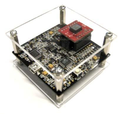
4 3 Hardware The SCA8X0-21X0-31X0 DEMO KIT USB interface board (black PCB) and SCA8X0-21X0-31X0 PWB (red PWB) are shown in figure 1. The USB interface card converts the USB interface to SPI interface of the accelerometer. SCA8x0, SCA21x0 or SCA31x0 sensor is soldered on the PWB which is connected to interface board. Figure 1. SCA8X0-21X0-31X0 demo USB interface board and SCA8X0-21X0-31X0 PWB. 4 GUI software SCA8X0-21X0-31X0 DEMO KIT is controlled via USB serial port by GUI software. The software must be installed into location that is suggested during installation procedure. The GUI software has several different display modes depending on the installed accelerometer on the PWB. The GUI displays and start up screens are presented below. VTI Technologies Oy 4/18

5 Screen capture of the GUI is presented in Figure Figure 2. SCA8X0-21X0-31X0 DEMO KIT Graphical User Interface 11. Table 1. The numbered items in Figure 2. Item Description 1 Temperature display. 2 Exit software, [Esc]-button also. 3 Data overflow; if the indicator is yellow, the acceleration register has an overflow measured acceleration is out of measuring range. 4 Scrolling acceleration display. 5 Save acceleration data in to a text file. 6 Freeze image, start / stop the scrolling window, [Page-Up] button also. 7 Zero gravitation ON / OFF. 8 Open / close the window extension with arrow button (available only in SCROLL display). 9 Pull down menu for acceleration [g] range (Y-axis). 10 Selected sensor type. 11 GUI software version number. 12 Averaging ON / OFF, number of samples for averaging. 13 Pull down menu for GUI display mode 14 Measured acceleration as a decimal number 15 Resultant vector ON/OFF in a 3 axis accelerometer VTI Technologies Oy 5/18


6 If more than one USB serial port devices are connected to PC, user must select the correct USB SERIAL PORT from pop-up window (Figure 3.). If user does not know the correct USB serial port number, please disconnect all other USB serial port devices from PC and restart the GUI software. Figure 3. USB serial port selection pop-up window. User needs to select the correct product type from PRODUCT SELECTION pop-up window (Figure 4). "SCA810 x 2g" is selected by default, product type can be changed from the list that appears when pressing the mouse left button the already selected product. Figure 4. Product selection pop-up window. Figure 5. Scroll display. SCROLL, continuously scrolling X / Y / Z / resultant accelerations (product dependent), see Figure 5. Acceleration is presented in [g]. User can: - change the acceleration scale - freeze the scrolling image - set averaging OFF - change the averaging factor - save acceleration data into file - enable resultant scrolling - Most of the actions/controls listed above are in the extension part of the window, which can be accessed by pressing the "ADVANCED" button (see Figure 2 and Table 1). VTI Technologies Oy 6/18


![DATA LOGGER, display where user can: - log data (maximum log time 5 s) - view the logged data in [g] - view the demonstrator speed as a function time (speed [m/s] is derived by integrating the](/docs-images/72/67557543/images/7-3.jpg "acceleration data) - view the inertial navigation results (distance [m] as a function of time is derived by integrating the acceleration data twice) Display available only with SCA31x0 products.")
7 BUBBLE LEVEL, two displays that show tilt angle, see Figure 6. Angle calculation is performed in GUI, not in the accelerometer. Display available only with SCA31x0 products. Figure 6. Bubble level display. 3D, 3 dimensional display with projections of each axis acceleration, see Figure 7. The minimum and maximum resultant accelerations as well as the current resultant acceleration are displayed on the right side of the graph. Minimum and maximum displays can be cleared by pressing the "Reset" button. Display available only with SCA31x0 products. Figure 7. 3D display. DATA LOGGER, display where user can: - log data (maximum log time 5 s) - view the logged data in [g] - view the demonstrator speed as a function time (speed [m/s] is derived by integrating the acceleration data) - view the inertial navigation results (distance [m] as a function of time is derived by integrating the acceleration data twice) Display available only with SCA31x0 products. Figure 8. Data logger display. To start the data logging press the "Start measurement" button. The actual data logging starts when the yellow "Measuring data" indicator lights up in the upper right corner of the window. Data is logged for predefined time period ( Measure time ). The results are calculated afterwards. VTI Technologies Oy 7/18
![The resultant (acceleration [g], speed [m/s] and distance [m]) is calculated from the respective 3-axis results as follows: 2 2 Res = x + y + z 2 Please notice that inertial navigation contains six](/docs-images/72/67557543/images/8-1.jpg "degrees of freedom and 3-axis accelerometer can handle only three degrees of freedom (rotations and tilting can not be detected when inertial navigation is performed only by 3-axis accelerometer).")

8 The resultant (acceleration [g], speed [m/s] and distance [m]) is calculated from the respective 3-axis results as follows: 2 2 Res = x + y + z 2 Please notice that inertial navigation contains six degrees of freedom and 3-axis accelerometer can handle only three degrees of freedom (rotations and tilting can not be detected when inertial navigation is performed only by 3-axis accelerometer). PWM (pulse width modulation) view shows the SCA8x0 output in PWM and simulated analog format. PWM(%) display shows the PWM output as 0/1 ratio in % and calculated analog output level. The view is available for SCA8x0 product versions that have the PWM output. Figure 9. PWM display. SELFTEST view shows the SCA8x0 output and GFC bit status over time during the self test. In the display the user can: - start the self test (single cycle) - vary the direction to which the sensing element is deflected during the self test To start the self test press the "START SELFTEST" -button. After the self test the actual output waveform is displayed on the screen. Figure 10. Self test display with SCA8x0 product. VTI Technologies Oy 8/18


9 SELFTEST view shows SCA21x0/31x0 output when the continuous self test has been switched on. In the display the user can: - start the continuous self test - read the self test status - reset the product - change the product offset To start the self test press the "START SELFTEST" -button. Figure 11. Self test display with SCA21x0/31x0 product. REGISTER CONFIG display offers user access in to accelerometer internal registers. Registers can be read and written. The written data format can be changed between binary and hexadecimal by pressing the "Bits / Hex" button. User can read automatically all configuration registers by pressing the Save reg content button. The results are saved into file and they can be viewed from Register content tab as well. Figure 12. Register configuration display. SPI frame format for each operation can be viewed from Waveform tab (see Figure 12). Figure 13. SPI waveform display. VTI Technologies Oy 9/18

10 RESET DEMO initialises the GUI software. µc software version is presented also. SCROLL display opens after RESET by default. Figure 14. Reset demo display. 4.1 Resetting GUI and µc SCA8X0-21X0-31X0 DEMO KIT GUI software can be reinitialised by selecting the Reset demo display from pull down menu. µc can be reinitialized by exiting from the GUI and then pressing the reset button (figure 1) on USB interface board. 4.2 Uninstalling the GUI and USB driver GUI software and USB driver (FTDI Serial Converter Driver) can be removed from Windows Control Panel Add/Remove Programs. VTI Technologies Oy 10/18
11 5 USB interface board circuit diagram SCA8X0-21X0-31X0 DEMO KIT SCA8X0-21X0-31X0 demo USB interface board circuit diagram is presented in following pages. Figure 15. SCA8X0-21X0-31X0 DEMO KIT USB interface board circuit diagram (sheet USB). VTI Technologies Oy 11/16
12 Figure 16. SCA8X0-21X0-31X0 DEMO KIT USB interface board circuit diagram (sheet µc). VTI Technologies Oy 12/16
13 Figure 17. SCA8X0-21X0-31X0 DEMO KIT USB interface board circuit diagram (sheet power, resistor R34 is 0 ohm instead of 470 ohm described in the schematics). VTI Technologies Oy 13/16


14 6 USB interface board PWB layout SCA8X0-21X0-31X0 DEMO KIT SCA8X0-21X0-31X0 DEMO KIT USB interface board PWB layout and silkscreen is presented below. Figure 18. SCA8X0-21X0-31X0 DEMO KIT USB interface board PWB layout. Figure 19. SCA8X0-21X0-31X0 DEMO KIT USB interface board VTI Technologies Oy 14/16
 and desktop PCs with Win2000 and WinXP operating system.")
, re-start the GUI again. The wait time in data transfer can be in increased on SETUP display (GUI software pull down menu).")
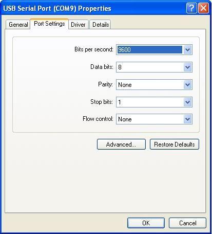
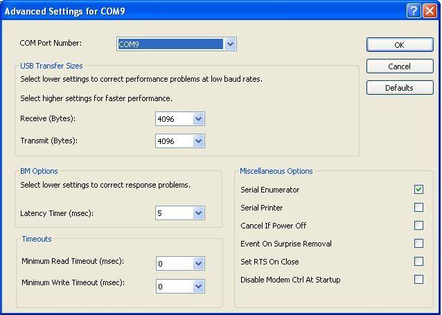
15 7 Troubleshooting SCA8X0-21X0-31X0 DEMO KIT Due to many PC environments, the interoperability can be limited. The SCA8X0-21X0-31X0 DEMO KIT has been tested with DELL laptops (Latitude D600, D610, D410) and desktop PCs with Win2000 and WinXP operating system. If the SCA8X0-21X0-31X0 DEMO KIT does not work properly or it s operation is limited, the following items may help to sort the problems out: Stop the GUI software, press the reset button program on demo USB interface board (see figure 1), re-start the GUI again. The wait time in data transfer can be in increased on SETUP display (GUI software pull down menu). SCA8X0-21X0-31X0 demo may not work properly if your PC has multiple USB serial ports installed. Please remove all other USB serial port devices. Close Windows HyperTerminal software, if you have used it. Check that USB driver LATENCY TIMER parameter is 5ms. Plug the demo USB cable in to PC and follow the steps (and screen captures) below: 1. Open control panel and select SYSTEM 2. Select DEVICE MANAGER from HARDWARE tab 3. Select USB SERIAL PORT from the list, right mouse click and select PROPERTIES" 4. Select ADVANVED from the USB Serial port Properties 5. Set the LATENCY TIMER to 5 ms (the 16ms default value is too slow for SCA8X0-21X0-31X0 DEMO KIT). 6. Press OK to all windows. 7. Restart the GUI software. Start Control panel VTI Technologies Oy 15/16

16 VTI Technologies Oy 16/16
Doc.Nr SCP1000 DEMO KIT User Manual
 Doc.Nr. 8268000.03 TABLE OF CONTENTS 1 Introduction...3 2 Quick start for using the...3 3 Hardware...4 4 GUI software...5 4.1 GUI software displays...7 4.1.1 USB serial port selection...7 4.1.2 Start up
Murata MEMS Demo User Manual
 Murata MEMS Demo Murata Electronics Oy Subject to changes 1/33 www.muratamems.fi Doc.Nr. 82175700 Rev.A TABLE OF CONTENTS 1 Introduction... 4 2 Quick start for using the Murata MEMS demo... 4 3 Hardware
Podium Plus Data Analysis Software. User Manual. SWIS10 Version
 SWIS10 Version Issue 1.10 February 2005 Contents 1 Introduction 6 1.1 What is Podium Plus? 6 1.2 About This Manual 6 1.3 Typographical Conventions 7 1.4 Getting Technical Support 7 2 Getting Started 8
Smart Monitor ZG2 User s Manual
 Smart Monitor ZG2 User s Manual Smart Sensors ZG2 Series 2D Profile Measuring Sensors CONTENTS SMART MONITOR ZG2 USER S MANUAL...1 SECTION 1 PREPARATIONS...2 Installing the Smart Monitor ZG2 on a Computer...
1) Installing Bluetooth software for Windows (A) Place installation CD into PC and setup should launch automatically.
 Installing Bluetooth software for Windows (A) Place installation CD into PC and setup should launch automatically.") 1) Installing Bluetooth software for Windows (A) Place installation CD into PC and setup should launch automatically. If setup does not launch, use Windows Explorer to navigate to the appropriate CD- ROM
1) Installing Bluetooth software for Windows (A) Place installation CD into PC and setup should launch automatically. If setup does not launch, use Windows Explorer to navigate to the appropriate CD- ROM
Flex Series User Guide
 User Programmable Current 4..20mA Digital RS485 Dual & Single Axis Up to 360º 2016 Flex Series User Guide Sensor Installation, Wiring, Flexware App Instructions Page 1 of 33 Page 2 of 33 Table of Contents
AqBiSS Electric Encoder
 INTRODUCTION AqBiSS Electric Encoder Evaluation Kits Product options: User Guide UG201 Individual kit for each encoder type, in one compact suitcase, containing one of these: EK-52 - RE 2 52 EK-37 - RE
Setting up the PC ready for BESA 11
 Setting up the PC ready for BESA 11 1 - Installing Driver. Important Note: Before you start to install the driver, please do not plug BESA 11 into the computer s USB port or else the installation will
INSTALLING THE PS3 XBOX READY SOFTWARE:
 INSTALLING THE PS3 XBOX READY SOFTWARE: 1. Insert the Installation CD to CD-ROM drive and execute Ready_Setup.exe NOTE: If it is the first time for the target USB disk using under this software, the software
Spectrometer Visible Light Spectrometer V4.4
 Visible Light Spectrometer V4.4 Table of Contents Package Contents...3 Trademarks...4 Manual Driver and Application installation...5 Manual Application Installation...6 First Start of the Application...8
RST INSTRUMENTS LTD.
 RST INSTRUMENTS LTD. VW0420 Analog VW Interface Instruction Manual Ltd. 11545 Kingston St Maple Ridge, BC Canada V2X 0Z5 Tel: (604) 540-1100 Fax: (604) 540-1005 Email: Info@rstinstruments.com i VW0420
MAXSANTAFEEVSYS User Manual
 MAXSANTAFEEVSYS User Manual Rev 0; 5/14 For pricing, delivery, and ordering information, please contact Maxim Direct at 1-888-629-4642, or visit Maxim Integrated s website at www.maximintegrated.com. Maxim
AN-619 APPLICATION NOTE
 APPLICATION NOTE One Technology Way P.O. Box 9106 Norwood, MA 02062-9106 Tel : 781/329-4700 Fax: 781/326-8703 www.analog.com Using the ADN8810 Demo Board v2.0 by Troy Murphy and Chris Kung OVERVIEW The
Evaluation Kit LDE-type Pressure Sensors
 Sensortechnics Corp. 2013 Revision A Table of Contents Table of Contents... i History... i Note...ii 1 Features... 1 2 Short Description... 1 3 Hardware... 1 4 Driver Installation and Software Setup...
Installing USB Drivers to Windows System
 1/9 Installing USB Drivers to Windows System Noptel Oy, Oulu Finland 1.3.2010 Noptel s USB devices uses USB/Serial Converters made by FTDI Ltd. The drivers for the USB Converter are provided by FTDI (http://www.ftdichip.com/).
Dot Matrix Indicator Programming
 Dot Matrix Indicator Programming Preparation: USB Dongle and USB cable. Part No. 100-159 (see page 3 Dongle Installation Instruction ). Display Programmer V2.0 (see page 10 Display Programmer V2 Installation
INTRODUCTION...1. Under Windows 98SE... 2 Under Windows ME... 6 Under Windows Under Windows XP...10
 CONTENTS INTRODUCTION...1 I. Install the USB-IrDA Adaptor driver... 2 Under Windows 98SE... 2 Under Windows ME... 6 Under Windows 2000... 9 Under Windows XP...10 II. Make sure the USB-IrDA Adaptor installed
Talk Light Time Manager User Instructions
 Talk Light Time Manager User Instructions Talk Light Time Manager Installation and User Instructions Technical Requirements: Windows 95, Windows 98, NT, ME, Windows 2000 or XP. Hard drive space for the
Podium Data Analysis Software. User Manual. SWIS10 Version
 SWIS10 Version Issue 1.00 March 2003 Contents 1 Introduction 5 1.1 What is Podium? 5 1.2 About This Manual 5 1.3 Typographical Conventions 6 1.4 Getting Technical Support 6 2 Getting Started 7 2.1 System
SCA620-EF1V1B SINGLE AXIS ACCELEROMETER WITH ANALOG INTERFACE
 Datasheet SCA620-EF1V1B SINGLE AXIS ACCELEROMETER WITH ANALOG INTERFACE The SCA620 accelerometer consists of a silicon bulk micro machined sensing element chip and a signal conditioning ASIC. The chips
User Guide Feb 5, 2013
 HI 8435 32 Sensor Array with Ground/Open or Supply/Open Sensors and SPI interface. Evaluation Board 23351 Madero, Mission Viejo, CA 92691. USA. Tel: + 1 949 859 8800 Fax: + 1 949 859 9643 Email: sales@holtic.com
TouchKit TouchScreen Controller User Guide for Windows 2000 / XP Version: 3.2.4
 TouchKit TouchScreen Controller User Guide for Windows 2000 / XP Version: 3.2.4 TouchKit Guide for Win2000/XP v3.2.4 0 CONTENT CHAPTER 1. TOUCH PANEL CONTROLLER...2 1.1 CONTROLLER...2 1.2 SPECIFICATIONS
PI Scanner User Guide
 PI Scanner User Guide Table of Contents 1. Highlights 2. Overview 3. Installation 3.1. PI Scanner Software Installation 3.2. USB to Serial Interface Board Installation 3.3. Programming the PI Scanner IP
USB driver and Software Installation. UPS Monitoring and Management Software
 USB driver and Software Installation UPS Monitoring and Management Software LEN.MAN.SOF.143 Rev.1.00/2008 Installing USB driver and Easy-Mon X for LEONICS UPS 1. Installing and uninstalling the USB driver
LOADING DRIVERS FOR SKYVIEW 2.0 XBEE INTERFACE USB DEVICE ON WINDOWS 8
 LOADING DRIVERS FOR SKYVIEW 2.0 XBEE INTERFACE USB DEVICE ON WINDOWS 8 After you have loaded the Skyview 2.0 software, with the xbee interface plugged in to your USB drive, you try to start the program
Evaluates: MAX MAX31856 Evaluation System. General Description. Features. EV System Contents. MAX31856 EV Kit Files. MAX31856 EV System Photo
 General Description The MAX31856 evaluation system (EV system) provides the hardware and software necessary to evaluate the MAX31856 thermocouple-to-digital converter. The EV system includes the MAX31856PMB1
Locktronics PICmicro getting started guide
 Page 2 getting started guide What you need to follow this course 2 Using the built-in programs 3 Create your own programs 4 Using Flowcode - your first program 5 A second program 7 A third program 8 Other
12.0 Setting up the PC ready for BESA 11
 12.0 Setting up the PC ready for BESA 11 12.1 - Installing Driver. Important Note: Before you start to install the driver, please do not plug BESA 11 into the computer s USB port or else the installation
Thank you for choosing Loadstar Sensors. Need additional help? Call us at or us at
 LoadVUE User Guide LoadVUE LoadVUE Lite Thank you for choosing Loadstar Sensors. Need additional help? Call us at 510-623-9600 or email us at support@loadstarsensors.com LoadVUE is compatible with Windows
USBG-8COM-PRO 8-Port USB to RS-232, 422, 485 Auto Setup Adapter Manual. Features & Specifications. Specifications
 USBG-8COM-PRO 8-Port USB to RS-232, 422, 485 Auto Setup Adapter Manual The USBG-8COM-PRO 2-Port Series Industrial I/O Adapters are advanced USB to Serial Adapters that connect to 1, 2, 4 or 8 RS- 232/422/485
RTE for WIN32. Installation Manual (Rev.7.0) Midas lab
 Midas lab") Midas lab REVISION HISTORY Date Revision Chapter Explanation of revision March 11,2000 4.0 RTE4W32 Ver.5.0 (First edition) January 10,2002 4.1 Add Windows XP support (RTE4W32 Ver.5.05) October 29,2002
Midas lab REVISION HISTORY Date Revision Chapter Explanation of revision March 11,2000 4.0 RTE4W32 Ver.5.0 (First edition) January 10,2002 4.1 Add Windows XP support (RTE4W32 Ver.5.05) October 29,2002
DS2740EVKIT+ High-Precision Coulomb Counter IC Evaluation Kit
 19-4843; Rev 1; 10/09 www.maxim-ic.com FEATURES Demonstrates the Capabilities of the DS2740 High-Precision Coulomb Counting IC Including: Real-Time Current Measurements High-Precision Current Accumulation
DOWNLOAD KIT CYCLOCOMPUTER INTRODUCTION. Download unit & Download Software [e-train Data Ver.3] for Windows 98/ME/2000/XP
![DOWNLOAD KIT CYCLOCOMPUTER INTRODUCTION. Download unit & Download Software [e-train Data Ver.3] for Windows 98/ME/2000/XP](/thumbs/78/78392561.jpg "DOWNLOAD KIT CYCLOCOMPUTER INTRODUCTION. Download unit & Download Software [e-train Data Ver.3] for Windows 98/ME/2000/XP") CYCLOCOMPUTER Download unit & Download Software [e-train Data Ver.3] for Windows 98/ME/2000/XP 0365510 (ENG) 3 INTRODUCTION The CC-TR100 Download Kit contains the software e-train Data TM Ver. 3 and the
CYCLOCOMPUTER Download unit & Download Software [e-train Data Ver.3] for Windows 98/ME/2000/XP 0365510 (ENG) 3 INTRODUCTION The CC-TR100 Download Kit contains the software e-train Data TM Ver. 3 and the
700TSU INSTALLATION MANUAL
 M 700TSU INSTALLATION MANUAL 2 Table of Contents Features...03 Specifications...04 Quick-Start...05 Remote Control...07 Hardware Installation...10 Software Installation...14 Touch Screen Driver Installation
Instructions for MX350 Firmware Upload
 Instructions for MX350 Firmware Upload MX350 Document AN10048 Page 1 of 39 Contents Section Description Page 1 Requirements 3 2 Install MX350 Setup Software 3 3 Download MX350 Firmware 4 4 Connect MX350
Cal-Bay Systems XY Plotter, Time-Base Recorder, Automated Tester. Users Guide. Rev 3.1
 Cal-Bay Systems XY Plotter, Time-Base Recorder, Automated Tester Users Guide Rev 3.1 Contents... 1 Quick Start Guide... 2 Selecting a Test Specification... 3 Clearing Traces... 4 Saving Traces...4 Loading
User Manual. LPC-StickView V1.1. for LPC-Stick. Contents
 User Manual LPC-StickView V1.1 for LPC-Stick Contents 1 What is LPC-Stick? 2 2 System Components 2 3 Installation 2 4 Updates 3 5 Starting the LPC-Stick View Software 4 6 Operating the LPC-Stick 6 7 Start
DATA LOGGING SOFTWARE FOR 4-WAY BALL VALVE DIGITAL MANIFOLD
 DATA LOGGING SOFTWARE FOR 4-WAY BALL VALVE DIGITAL MANIFOLD The Mastercool Data Logger Application provides all the necessary Recorder and Display Functions to record, display and save new data or playback
DVK User Manual. Scope. Related Melexis Products. Introduction
 Scope The MLX90129 from Melexis is a sensor IC with an integrated 13.56 MHz high frequency (HF) interface that allows sensor data to be read with a HF radio frequency identification (RFID) reader. The
Quick Start Guide: RL78G14 Motor Control Starter Kit
 Document Contents 1.0 Introduction 1 2.0 Board Layout 1 3.0 Stand Alone Demonstration Mode 2 4.0 Installation 3 5.0 Using the GUI 4 6.0 RL78/G14 Programming 6 7.0 RL78/G14 Debugging 7 8.0 Next Steps 8
Preliminary. SLDU022 User s Manual. PGA300 Pressure and Temperature Sensor Signal Conditioner. Copyright 2016, Texas Instruments Incorporated
 SLDU022 User s Manual PGA300 Pressure and Temperature Sensor Signal Conditioner Copyright 2016, Texas Instruments Incorporated Revision History Revision Date Descriptions/Comments 1.0 2.0 31 -Jan - 2014
OPERATING MANUAL AND TECHNICAL REFERENCE
 MODEL WFG-D-130 HIGH SPEED DIGITAL 3 AXIS FLUXGATE MAGNETOMETER OPERATING MANUAL AND TECHNICAL REFERENCE December, 2012 Table of Contents I. Description of the System 1 II. System Specifications.. 2 III.
Podium Data Analysis Software. User Manual. RCA40 Version
 RCA40 Version Issue 1.00 March 2003 Contents 1 Introduction 5 1.1 What is Podium? 5 1.2 About This Manual 5 1.3 Typographical Conventions 6 1.4 Getting Technical Support 6 2 Getting Started 7 2.1 System
Troubleshooting. Note. SC485, USB485 and USB485B. Table of Contents.
 SC485, USB485 and USB485B Troubleshooting Note www.lightorama.com Use this document if: 1. You want to locate the Windows communications port name being used by the RS485 adapter. 2. You believe the USB
TouchKit Touch Panel User manual for Windows9X/ME Version: 3.1.4
 TouchKit Touch Panel User manual for Windows9X/ME Version: 3.1.4 TouchKit Touch Panel v3.1.4 0 CONTENT CHAPTER 1. TOUCH PANEL CONTROLLER... 2 1.1 CONTROLLER... 2 1.2 SPECIFICATIONS AND FEATURES... 3 CHAPTER
Cyclops Explorer Product Overview and Instructions
 Overview: The Cyclops Explorer is a complementary product and handy tool when using your Cyclops Submersible Sensors in the lab. Plugging directly into the USB port on your computer, the Explorer guides
RPLIDAR A2. Development Kit User Manual. Low Cost 360 Degree Laser Range Scanner. Model: A2M4. Shanghai Slamtec.Co.,Ltd rev.1.
 2016-10-28 rev.1.1 RPLIDAR A2 Low Cost 360 Degree Laser Range Scanner Development Kit User Manual Model: A2M4 www.slamtec.com Shanghai Slamtec.Co.,Ltd Contents CONTENTS... 1 OVERVIEW... 3 ITEMS IN THE
Accurate Lambda Meter ALM GUI. User Manual V1.3 COPY RIGHTS ECOTRONS LLC ALL RIGHTS RESERVED.
 Accurate Lambda Meter ALM GUI User Manual V1.3 COPY RIGHTS ECOTRONS LLC ALL RIGHTS RESERVED Http://www.ecotrons.com Note: If you are not sure about any specific details, please contact us at info@ecotrons.com.
TouchScreen Controller User Manual
 TouchScreen Controller User Manual for Windows 9X / ME Version: 3.4.0 Customer : Model : 32-4W232/4WUSB/5W232/5WUSB-BB Date : Version: Acceptance Sheet Onetouch Technologies Co., Ltd. (Supplier) (Purchaser)
AMT203 ABSOLUTE ENCODER Demo Kit User Guide DISCONTINUED
 AMT203 ABSOLUTE ENCODER Demo Kit User Guide PART NUMBER: AMT203 AMT-DMBD Demo Board DESCRIPTION: date 2 of 13 DEMO KIT USER GUIDE The AMT-DMBD Demo Board is designed for testing and configuring the AMT
Mini USB to RS-232 Serial Adapter DB-9 Male Converter. Product Manual. Coolgear Version 1.0 January 2018 Model Number: USBG-232MINI.
 Mini USB to RS-232 Serial Adapter DB-9 Male Converter Product Manual Coolgear Version 1.0 January 2018 Model Number: USBG-232MINI 2 USBG-232MINI PRODUCT MANUAL Revision History Revision Date Author Comments
QUICK START. DevCom2000 User Manual
 QUICK START DevCom2000 uses Device Descriptions (DDs) to access data stored in the memory of the smart field device. These DDs are developed by the manufacturer for their products and, in turn, distributed
E401. User Manual. The New Vision of Touch
 E401 User Manual The New Vision of Touch E401 User Manual OVERVIEW This kit is designed for evaluation and development of QT401-based QSlide slider controls. It includes a fully assembled slider PCB, demo
For more detailed information about this product please refer to the QT510 datasheet.
 E510 1 User Manual 2 E510 User Manual OVERVIEW This kit is designed for evaluation and development of QT510-based QWheel Rotary slider. It includes a fully assembled rotary slider evaluation board, user
USB-COMi-TB USB to Industrial Single RS-422 / 485 Adapter Manual. Specifications and Features
 USB-COMi-TB USB to Industrial Single RS-422 / 485 Adapter Manual The USB-COMi-TB USB-to-Industrial Single RS-422/485 Adapter is designed to make industrial communication port expansion quick and simple.
MISUMI SUPPORT SOFTWARE. RS-Manager. User s Manual C1 / C21 / C22 / P1 EXWM KE114. Ver. 2.00
 MISUMI SUPPORT SOFTWARE RS-Manager User s Manual C1 / C21 / C22 / P1 Ver. 2.00 EXWM14200 KE114 CONTENTS RS-Manager User s Manual Before getting started 1 1. About RS-Manager 2 2. Installing and uninstalling
Bridge Cable User s Guide
 Bridge Cable User s Guide Table of Contents Overview -------------------------------------------------------------------- 2 Driver Installation --------------------------------------------------------
Thermal Transient Test Installation and Operating Manual
 Thermal Transient Test Installation and Operating Manual 2705A De La Vina Street Santa Barbara, California 93105 Telephone (805) 682-0900 descon@silcom.com www. santabarbaraautomation.com Installation
DBT-120 Bluetooth USB Adapter
 DBT-120 Bluetooth USB Adapter Rev.2.1 (09/25/2002) 2 Contents Introduction... 5 Package Contents... 6 Installing Bluetooth Software... 6 Hardware Installation... 8 Introduction to Bluetooth Software...
Table of Contents. 1. Intended Use Overview Materials Required System Requirements User Mode 4
 Table of Contents 1. Intended Use.. 3 2. Overview.. 3 2.1 Materials Required. 3 2.2 System Requirements. 3 2.3 User Mode 4 3. Installation Instructions.. 5 3.1 Installing the On Call Diabetes Management
SONOFLOW Monitor Short Instructions. For SONOFLOW Sensors of the Series CO.55 V2.0
 SONOFLOW Monitor Short Instructions For SONOFLOW Sensors of the Series CO.55 V2.0 Manufacturer: SONOTEC Ultraschallsensorik Halle GmbH Monitor model: SONOFLOW Monitor V02.xx For sensor types: Flow Sensors
User Manual. LPC-StickView V3.0. for LPC-Stick (LPC2468) LPC2478-Stick LPC3250-Stick. Contents
 LPC2478-Stick LPC3250-Stick. Contents") User Manual LPC-StickView V3.0 for LPC-Stick (LPC2468) LPC2478-Stick LPC3250-Stick Contents 1 What is the LPC-Stick? 2 2 System Components 2 3 Installation 3 4 Updates 3 5 Starting the LPC-Stick View Software
User Manual LPC-StickView V3.0 for LPC-Stick (LPC2468) LPC2478-Stick LPC3250-Stick Contents 1 What is the LPC-Stick? 2 2 System Components 2 3 Installation 3 4 Updates 3 5 Starting the LPC-Stick View Software
Firmware, Database, & PC Application Update Installation Instructions
 Firmware, Database, & PC Application Update Installation Instructions IMPORTANT Please read before you begin the installation. To avoid possible errors, it is recommended to install the updates as described
Evaluates: DS28E80. DS28E80 Evaluation System. General Description. Benefits and Features. EV Kit Contents
 General Description The DS28E80 evaluation system (EV system) consists of a single evaluation kit (EV kit) that includes a package of five DS28E80 devices in a 6-pin TDFN package, a DS9120Q+ socket board
Windows 8 / 7 CONTENTS. USB to RS-422 Converter. Part Number: USB FEATURES. 2 SPECIFICATIONS. 2 CONNECTIONS.. 3
 CONTENTS USB to RS-422 Converter Part Number: USB-422-1 INTRODUCTION 2 FEATURES. 2 SPECIFICATIONS. 2 PIN ASSIGNMENT 2 CONNECTIONS.. 3 DRIVER INSTALLATION QUICK GUIDE.. 3 DRIVER INSTALLATION EXAMPLES..
Windows 8 / 7 CONTENTS. USB to RS-485 Converter. Part Number: USB FEATURES. 2 SPECIFICATIONS. 2 CONNECTIONS.. 3
 CONTENTS USB to RS-485 Converter Part Number: USB-485-1 INTRODUCTION 2 FEATURES. 2 SPECIFICATIONS. 2 PIN ASSIGNMENT 2 CONNECTIONS.. 3 DRIVER INSTALLATION QUICK GUIDE.. 3 DRIVER INSTALLATION EXAMPLES..
MMA845xQ Sensor Toolbox User s Guide
 Freescale Semiconductor Document Number: MMA845xQSTUG User s Guide Rev. 1, 02/2012 MMA845xQ Sensor Toolbox User s Guide 1 Introduction The Freescale MMA845xQ sensor toolbox accelerometer kit provides hardware
Setup for LAUSDnet - Windows 95/98/ME Revised 8/1/2001
 Setup for LAUSDnet - Windows 95/98/ME Revised 8/1/2001 Dial Up Networking Setup The following assumes that the Dial-Up Networking portions of Windows 95/98/ME have already been installed. If they have
Tech Memo # Software Engineering. Normal PRIORITY: DATE: April 17 th, 2015
 Software Engineering Tech Memo #15-0001 PRIORITY: Normal DATE: April 17 th, 2015 TITLE: PRODUCTS AFFECTED: TOOLS REQUIRED: NOTE: INTRODUCTION: How to install and configure Adaptive Sign Server on a Windows
EVAL-ADT7516. SPI -/I 2 C -Compatible, Temperature Sensor, 4-Channel ADC and Quad Voltage Output DAC FEATURES APPLICATIONS
 SPI -/I 2 C -Compatible, Temperature Sensor, 4-Channel ADC and Quad Voltage Output DAC EVAL-ADT7516 FEATURES Easy evaluation of the ADT7516 Can be used to emulate ADT7517 and ADT7519 Evaluation software
USB 3.0 Mini Docking Station
 USB 3.0 Mini Docking Station User Manual Ver. 1.00 All brand names and trademarks are properties of their respective owners. Contents: Chapter 1: Introduction... 3 1.1 Product Introduction... 3 1.2 Features...
UG MCAP II & ecap II Smartware & USB Drivers Installation
 MCAP II & ecap II Smartware & USB Drivers Installation Sept 4, 2008 Copyright 2008 by QEI Inc. ALL RIGHTS RESERVED NOTICE The information in this document has been carefully checked and is believed to
INTERFACE & SOFTWARE GUIDE
 TM INTERFACE & SOFTWARE GUIDE Wireless Remote Display USB Converter Battery Sensor Setup DataLogger Software r e m o t e i n t e r f a c e escape enter status w w w. s k y s t r e a m e n e r g y. c o
RM024 DVK USER GUIDE VERSION 1.2
 USER GUIDE VERSION 1.2 Americas: +1-800-492-2320 Asia: +852-2923-0610 REVISION HISTORY Version Revision Date Change Description Approved By 1.0 20 Dec 2012 Initial Release Chris Downey 1.1 15 Apr 2014
USER MANUAL for USB Data Link
 Driver Installation Under Win 95 OSR2.1 1.Step1: Double click "My Computer" "System Properties" "Device Manager" Step2: While installing USB Data Link Cable under Windows 95 OSR2.1 mode, make sure "Universal
VSM Manager. The VSM Manager is a Windows GUI that can be installed to serially control Genesis Matrixes with a firmware of version 2.5 or later.
 VSM Manager Table of Contents Overview...1 Getting Started...1 Toolbar... 2 Serial Connection... 2 Refresh... 3 Help... 3 Tab Pages... 4 General... 4 Control...5 Schedule... 6 Command... 6 Communications...
DS2788K Evaluation Kit Standalone Fuel Gauge IC with LED Display Drivers
 s DS2788K Evaluation Kit Standalone Fuel Gauge IC with LED Display Drivers www.maxim-ic.com FEATURES Demonstrates the capabilities of the DS2788 Standalone Fuel Gauge IC with LED Display Drivers, including:
DataNet Installation Guide + Quick Start Guide Updated: August 2008
 DataNet Installation Guide + Quick Start Guide Updated: August 2008 This document contains instructions for downloading and installing the DataNet software, supporting Fourier Systems DataNet data logging
TouchScreen for Display & Panel-PC
 TouchScreen for Display & PanelPC User Manual for Windows 2000 / XP Version: 4.0.2 TouchKit Manual for Win2000/XP v4.0.2 Page 1 CONTENT CHAPTER 1. TOUCH PANEL CONTROLLER... 3 1.1 CONTROLLER... 3 1.2 SPECIFICATIONS
PC Spa Dashboard Control User Guide
 EL/GL Series - Mach 3 PC Spa Dashboard Control User Guide 900854 balboa-instruments.com Page 1 Page 2 PC SPA DASHBOARD The PC Spa Dashboard can be used with the EL8000, EL2000, EL1000 and GL systems. System
MAXREFDES24EVSYS User Manual
 MAXREFDES24EVSYS User Manual Rev 1; 1/15 ADCLITE2 ANALOG SIGNAL CAPTURE GUI Windows PC REFDES24 4-CHANNEL ANALOG OUTPUT GUI 20 30VDC (>150mA) MAXREFDES24 MAX1659 LDO MAX17498 FLYBACK CONTROL MAX6126 VREF
CENTER 521 INSTRUCTION MANUAL 4-Channel Thermocouple Data Logger (with Bluetooth) (Types K, J, T, N, E, R, S)
 (Types K, J, T, N, E, R, S)") CENTER 521 INSTRUCTION MANUAL 4-Channel Thermocouple Data Logger (with Bluetooth) (Types K, J, T, N, E, R, S) CONTENTS 1. GENERAL DESCRIPTION... 1 2. SAFETY INFORMATION... 2 3. FEATURES... 2 4. SPECIFICATIONS...
CENTER 521 INSTRUCTION MANUAL 4-Channel Thermocouple Data Logger (with Bluetooth) (Types K, J, T, N, E, R, S) CONTENTS 1. GENERAL DESCRIPTION... 1 2. SAFETY INFORMATION... 2 3. FEATURES... 2 4. SPECIFICATIONS...
INSTALLATION AND OPERATING MANUAL BUNN-O-MATIC CORPORATION POST OFFICE BOX 3227 SPRINGFIELD, ILLINOIS PHONE: (217) FAX:
 FAX:") ! BUNN BRW BrewWISE Recipe Writer WARNING DISCONNECT FROM POWER SOURCE BEFORE REMOVAL OF ANY PANEL OR REPLACEMENT OF ANY COMPONENT! INSTALLATION AND OPERATING MANUAL BUNN-O-MATIC CORPORATION POST OFFICE
! BUNN BRW BrewWISE Recipe Writer WARNING DISCONNECT FROM POWER SOURCE BEFORE REMOVAL OF ANY PANEL OR REPLACEMENT OF ANY COMPONENT! INSTALLATION AND OPERATING MANUAL BUNN-O-MATIC CORPORATION POST OFFICE
CommLink IV Technical Guide
 www.wattmaster.com CommLink IV Technical Guide Table of Contents General Information... 3 CommLink IV Overview...3 Optional IP Module Kit...3 Optional Remote Link II...3 Installing CommLink IV ONLY...3
eturboware 4.x For Windows 2000/XP User s Guide Part No: M , Ver:1.0
 eturboware 4.x For Windows 2000/XP User s Guide Part No: M3-000016, Ver:1.0 The information in this document is subject to change without notice. No part of this document may be reproduced or transmitted
WUA-1810 AC1200 Dual Band Wireless USB Network Adapter User Manual V1.0
 WUA-1810 AC1200 Dual Band Wireless USB Network Adapter User Manual V1.0 Digital Data Communications Asia Co., Ltd. http://www.level1.com 0 / 19 Table of Contents Part 1: Working on Windows PC------------------------------------------------------------P2
EasyMP Monitor Operation Guide Ver.4.31
 EasyMP Monitor Operation Guide Ver.4.31 2 Notations Used in This Guide The following table shows the symbols used in this manual, along with descriptions of what they mean. s Indicates a page where detailed
Navigator Software User s Manual. User Manual. Navigator Software. Monarch Instrument Rev 0.98 May Page 1 of 17
 User Manual Navigator Software Monarch Instrument Rev 0.98 May 2006 Page 1 of 17 Contents 1. NAVIGATOR SOFTWARE 2. INSTALLATION 3. USING NAVIGATOR SOFTWARE 3.1 STARTING THE PROGRAM 3.2 SYSTEM SET UP 3.3
Figure 1. Proper Method of Holding the ToolStick. Figure 2. Improper Method of Holding the ToolStick
 TOOLSTICK C8051F560 DAUGHTER CARD USER S GUIDE 1. Handling Recommendations To enable development, the ToolStick Base Adapter and daughter cards are distributed without any protective plastics. To prevent
S Fully Assembled and Tested. Maxim Integrated Products 1
 19-4808; Rev 0; 1/10 MAX5386M Evaluation System General Description The MAX5386M evaluation kit (EV kit) is an assembled and tested PCB that features the MAX5386M 50kI dual digital potentiometers. The
Product Manual. 2 Port USB to RS-422 /485 Optical Isolated Adapter. Coolgear, Inc. Version 1.1 March 2018 Model Number: USB-2COMi-Si-M
 2 Port USB to RS-422 /485 Optical Isolated Adapter Product Manual Coolgear, Inc. Version 1.1 March 2018 Model Number: USB-2COMi-Si-M 2 USB-2COMi-Si-M Product Manual Revision History Revision Date Author
ic-mh16 Evaluation Software Software Description
 Rev A1, Page 1/14 DESCRIPTION ic-haus ic-mh16 evaluation software is developed for PCs running the Windows operating system. The evaluation software is developed in LabVIEW and requires a one-time installation
TMC428 Evaluation Kit V2.0 Manual English
 TMC428 Evaluation Kit V2.0 Manual English Version: 2.01 July 30 th, 2002 2 TMC428 Evaluation Kit V2.01 Version Version Date Author Remarks 2.00 2002-07-29 OK Created from version 1.02 2.01 2002-07-30 OK
This 4-port RS-422/485 Adapter is provided with an external switching power adapter in the package.
 USB-4COMi-M USB to Quad RS-422/485 to Serial Adapter Manual The USB to Industrial Quad RS-422/485 Adapter is designed to make industrial communication port expansion quick and simple. Connecting to a USB
Olimex Field Update Kit
 Olimex Field Update Kit Table of Contents Overview... 2 To download the field update software... 2 To install the HQLoader software... 2 To install the USB to Serial Converter driver... 2 To install the
HH-521BT 4-Channel Thermocouple Data Logger (with Bluetooth) (Types K, J, T, N, E, R, S) Instruction Manual
 (Types K, J, T, N, E, R, S) Instruction Manual") HH-521BT 4-Channel Thermocouple Data Logger (with Bluetooth) (Types K, J, T, N, E, R, S) Instruction Manual CONTENTS 1. GENERAL DESCRIPTION... 2 2. SAFETY INFORMATION... 2 3. FEATURES... 2 4. SPECIFICATIONS...
HH-521BT 4-Channel Thermocouple Data Logger (with Bluetooth) (Types K, J, T, N, E, R, S) Instruction Manual CONTENTS 1. GENERAL DESCRIPTION... 2 2. SAFETY INFORMATION... 2 3. FEATURES... 2 4. SPECIFICATIONS...
DiBos/DiBos Micro. Operation Manual
 DiBos/DiBos Micro en Operation Manual DiBos/DiBos Micro Table of Contents en 3 Table of Contents 1 Program Start/Login 7 1.1 Starting the Program 7 1.2 Logging on to the System 7 1.2.1 Logging on to the
Bosch Recording Station. Operating Manual
 Bosch Recording Station en Operating Manual Bosch Recording Station Table of Contents en 3 Table of Contents 1 Program Start/Login 5 1.1 Starting the Program 5 1.2 Logging on to the System 5 1.2.1 Logging
Quick-Start Guide. BNS Solutions. QSK62P Plus
 BNS Solutions Quick-Start Guide QSK62P Plus RS-232 Port Link LED 8-character x 2-line LCD Expansion Port (2) Reset Switch Power LED Thermistor I/O Ring (4) M16C MCU Analog Adjust Pot MCU Crystal Expansion
EMP Monitor Operation Guide V4.30
 EMP Monitor Operation Guide V4.30 Meanings of symbols used The following table shows the symbols used in this manual, along with descriptions of what they mean. Attention s Indicates procedures which may