HeadAmp6 PROFESSIONAL SIX CHANNEL HEADPHONE AMPLIFIER OPERATION MANUAL
|
|
|
- Jonas Wilkins
- 6 years ago
- Views:
Transcription

1 HeadAmp6 PROFESSIONAL SIX CHANNEL HEADPHONE AMPLIFIER OPERATION MANUAL 1
2 IMPORTANT SAFETY INSTRUCTIONS READ FIRST This symbol, wherever it appears, alerts you to the presence of uninsulated dangerous voltage inside the enclosure. Voltage that may be sufficient to constitute a risk of shock. This symbol, wherever it appears, alerts you to important operating and maintenance instructions in the accompanying literature. Please read manual. Read Instructions: Retain these safety and operating instructions for future reference. Heed all warnings printed here and on the equipment. Follow the operating instructions printed in this user guide. Do Not Open: There are no user serviceable parts inside. Refer any service work to qualified technical personnel only. Power Sources: Only connect the unit to mains power of the type marked on the rear panel. The power source must provide a good ground connection. Power Cord: Use the power cord with sealed mains plug appropriate for your local mains supply as provided with the equipment. If the provided plug does not fit into your outlet consult your service agent. Route the power cord so that it is not likely to be walked on, stretched or pinched by items placed upon or against. Grounding: Do not defeat the grounding and polarization means of the power cord plug. Do not remove or tamper with the ground connection on the power cord. Ventilation: Do not obstruct the ventilation slots or position the unit where the air required for ventilation is impeded. If the unit is to be operated in a rack, case or other furniture, ensure that it is constructed to allow adequate ventilation. Moisture: To reduce the risk of fire or electrical shock do not expose the unit to rain, moisture or use in damp or wet conditions. Do not place a container of liquid on it, which may spill into any openings. Heat: Do not locate the unit in a place close to excessive heat or direct sunlight, as this could be a fire hazard. Locate the unit away from any equipment, which produces heat such as: power supplies, power amplifiers and heaters. Environment: Protect from excessive dirt, dust, heat, and vibration when operating and storing. Avoid tobacco ash, drink spillage and smoke, especially that associated with smoke machines. Handling: To prevent damage to the controls and cosmetics avoid rough handling and excessive vibration. Protect the controls from damage during transit. Use adequate padding if you need to ship the unit. To avoid injury to yourself or damage to the equipment take care when lifting, moving or carrying the unit. Servicing: Switch off the equipment and unplug the power cord immediately if it is exposed to moisture, spilled liquid, objects fallen into opening, or the power cord or plug becomes damaged during a lightning storm or if smoke odor or noise is noted. Refer servicing to qualified technical personnel only. Installation: Install the unit in accordance with the instructions printed in the user guide. 2
3 The ART HeadAmp6 Professional Six Channel Headphone Amplifier IMPORTANT SAFETY INSTRUCTIONS READ FIRST...1 INTRODUCTION...4 INSTALLATION...4 AC Power Hookup... 4 Analog Audio Connections... 4 CONTROLS and JACKS...5 Front Panel... 5 Direct In Jack... 5 Master Volume Control... 5 Mute L, Mute R, and Mono Switches... 5 Stereo Aux In Jack... 5 Out Jack... 5 Balance Control... 6 Level Control... 6 Power Switch... 6 Rear Panel... 6 Balanced Main Inputs... 6 Balanced Main Thru... 6 Stereo Headphone Outputs... 7 OPERATION...8 APPLICATIONS...9 WARRANTY INFORMATION...11 SERVICE...11 HEADAMP6 SPECIFICATIONS...12 List of Figures FIGURE 1 - Master Volume, Direct In, and Channel One...5 FIGURE 2 - Rear Panel Inputs...6 FIGURE 3 - Rear Panel Headphone Outputs...7 FIGURE 4 - Headphone Distribution Application...9 FIGURE 5 - Block Diagram
4 INTRODUCTION The HeadAmp6 is a full-featured six -channel stereo headphone amplifier that includes six auxiliary inputs to allow separate mixes on each headphone channel. Each output channel also features a dual function Balance control which will pan between Left & Right sides of the main signal bus, or vary the Mix between the main signal bus and the Auxiliary input for that respective channel. Each output channel includes one front and two rear panel stereo 1/4-inch TRS headphone jacks for ease of installation and quick patching capability. Mono, Mute L, and Mute R buttons on each channel select between four operating modes; 1) Stereo, 2) Mono Left, 3) Mono Right, 4) Mono Both (Left & Right) for versatile monitoring solutions. Independent output level controls on each channel personalize monitoring levels. Input options include XLR and 1/4-inch TRS balanced inputs with matching Thru jacks for bridging multiple units. An additional front panel stereo 1/4-inch TRS Direct In jack for quick patch override of the rear panel inputs is included for quick insertion of any stereo source. Master Volume control sets the main signal bus level. Eight-segment precision LED level metering on the main bus and four-segment indicators on each output channel provide visual feedback of the signal level at all key points. INSTALLATION The HeadAmp6 may be used in a wide variety of applications and environments. Its rack-mountable steel and aluminum enclosure is both attractive and designed for continuous professional use. Mounting location is not critical. However, for better performance and greater reliability we recommend that you not place the unit on top of power amps or other sources of extreme heat, or strong magnetic fields. AC Power Hookup The HeadAmp6 has an internal power supply. Only connect the unit to mains power of the type marked on the rear panel. The power source must provide a good ground connection, and the ground pin on the mains plug should never be defeated. Analog Audio Connections Audio connections to and from the HeadAmp6 are: Rear Balanced Inputs and Outputs: [XLR] Pin 2 = Pos(+), Pin 3 = Neg(-), Pin 1 = Ground [1/4-inch] Tip = Pos(+), Ring = Neg(-), Sleeve = Ground Front Stereo Aux 1/4-inch Inputs: Tip = Left, Ring = Right, Sleeve = Ground Front Direct 1/4-inch Input: Tip = Left, Ring = Right, Sleeve = Ground Front and Rear Stereo Headphone 1/4-inch Outputs: Tip = Left, Ring = Right, Sleeve = Ground Six Independent High-Power Headphone Amplifier Channels Dual Function Balance/Mix Control per Channel Front Panel Stereo Aux Input for each Channel Multiple Monitoring Settings per Channel Individual Output Level Control per Channel Precision Four Segment LED Metering Per Channel Master Volume Control w/ Eight Segment LED Metering Front Panel Direct In Jack One Front and Two Rear Mounted Headphone Jacks per Channel Connects and Drives up to 18 Headphones Simultaneously XLR and 1/4 Main Inputs and Outputs Parallel Main Outputs for Multiple Unit Use 4

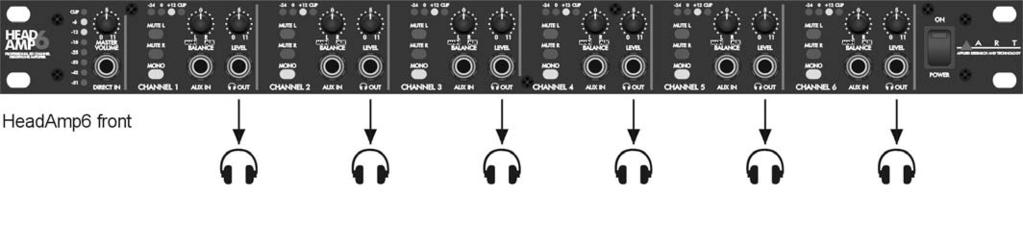
5 CONTROLS and JACKS Front Panel FIGURE 1 - Master Volume, Direct In, and Channel One Direct In Jack The 1/4-inch TRS (Tip, Ring, Sleeve) jack on the front panel provides a stereo unbalanced input which, when used, will override the rear panel balanced inputs. This input is useful for when you want to temporarily insert a different main input signal from what is connected to the rear inputs, or simply make an unbalanced TRS style connection to another headphone output source. Master Volume Control This control adjusts the level of the main signal bus. The eight-segment LED level meter located just to the left of the MASTER VOLUME control displays the audio level on the main signal bus. Mute L, Mute R, and Mono Switches These switches set the stereo headphone outputs to one of three operating modes. (This affects only the headphone outputs and occurs post (after) the balance/mix, and level control sections.) 1) All Switches Out = Stereo 2) Mute L In & Mute R Out & Mono In = Right Channel Only in Mono 3) Mute R In & Mute L Out & Mono In = Left Channel Only in Mono Stereo Aux In Jack These stereo TRS jacks provide a means of inserting a direct stereo signal into an individual headphone channel. When a plug is inserted into an AUX INPUT jack the BALANCE control for that particular channel changes function to become a mix control adjusting the mix between the signal coming into that channels stereo AUX IN and the main signal bus. Out Jack This stereo TRS 1/4-inch jack provides a connection for each of six output channels to stereo headphones or to additional headphone distribution amplifiers. Two identical output jacks are provided on the rear panel for each channel as well. 5
6 Balance Control This control provides one of two functions depending on whether there is a plug inserted into the stereo AUX IN for a particular channel. With no plug inserted into the AUX IN jack, the control will vary the Left / Right balance of the main signal bus feed to the channel. With a plug inserted, the control changes function to vary the mix between the stereo signals coming from the main signal bus and the stereo signals coming from the AUX IN for that respective channel. By feeding a return signal for only the vocal microphone of a particular musician into the AUX IN you can use the BALANCE control as a More Me control by varying the mix between the microphone signal alone, and the main signal bus audio. This effect is heard only in the individual headphones of the specific channel. Level Control This control varies the audio output level feeding the front and rear panel 1/4-inch stereo output jacks for each respective channel. The four-segment LED level meter, located above the switches on each channel, displays the audio level for each channel output. Power Switch This rocker switch turns the AC power On and Off. A small LED indicator in the rocker button illuminates to indicate that the power is on. Rear Panel FIGURE 2 - Rear Panel Inputs Balanced Main Inputs These XLR and 1/4-inch TRS jacks are active balanced and are used for line level signals. The gain sensitivity is identical for both the XLR and 1/4-inch TRS jacks. Signals applied to these jacks feed the main signal buss. (NOTE: the front panel DIRECT IN jack overrides these inputs when it is used.) Balanced Main Thru These XLR and 1/4-inch TRS jacks are hardwired in parallel with the corresponding BALANCED MAIN INPUT jacks. The BALANCED MAIN THRU jacks are useful for daisy chaining multiple HeadAmp6 units together. 6

7 FIGURE 3 - Rear Panel Headphone Outputs Stereo Headphone Outputs These stereo TRS jacks are the main outputs for each channel of the headphone amplifier. They are wired in parallel with the corresponding output jacks on the front panel. Either front panel, rear panel, or both front and rear panel outputs can be used simultaneously to drive headphones or they can be used as feeds to additional headphone amplifiers in a distributed audio network. NOTE: The HeadAmp6 is optimized to drive typical headphone load impedances of 32 to 600 Ohms. It is not recommended to drive total impedances lower than 16 Ohms however it can be done without damage and will result in limited maximum output power, and possible clipping distortion depending on the output level and load. When driving multiple headphones from an individual output channel of the HeadAmp6 (paralleling), the available output power is split among the various headphones, and due to the combined load impedances the output may also become limited by premature clipping of the output signal. Most modern headphones are medium to high impedance and require only milliwatts to achieve full acoustic output so this should rarely be a problem. If it is a problem simply lower the level or lower the total count of headphones on a particular channel in order to increase the total load impedance as seen by the channel output. There is no direct relationship between headphone load impedance and SPL output. The relevant specification that determines acoustic output is the sensitivity spec of the headphone, i.e. how much SPL it will put out for a given level of input signal, usually rated at 1 mw. Sensitivity is determined by the overall design and construction of the transducer. Typically the power required is about 1/1000th of the equivalent amplifier power required to drive a speaker. Therefore typical headphone amplifiers provide power levels in the 10mW to 20 mw ranges in order to achieve a very reasonable SPL output. Even an 8 Ohm headphone (if you can find one since they are rare) can be driven to full SPL output by the HeadAmp6 if it has a high enough sensitivity, regardless of the fact that the output voltage swing will be limited due to the overload protection circuitry. 7
8 OPERATION Start with the MASTER VOLUME and LEVEL controls on all channels set fully counter-clockwise. Set the BALANCE controls to their 12 o clock positions. Set all MUTE and MONO switches to their OUT position. Using the appropriate balanced or unbalanced cables, (unbalanced cables will work in the rear panel inputs as well, but with the remote possibility of increased noise), connect the rear panel BALANCED MAIN Inputs to the audio monitor signal source to be distributed to the headphones. Alternatively connect the audio signal source to the front panel DIRECT IN jack using a stereo TRS 1/4-inch plug. If connecting more than one HeadAmp6 to the same audio monitor signal source, simply daisy-chain the units by connecting from the BALANCED MAIN THRU connectors of the first unit to the BALANCED MAIN INPUT connectors of the next unit, etc. (NOTE: Daisy chaining only works with the rear panel connectors. The front panel DIRECT IN jack only feeds its respective HeadAmp6 unit directly.) Connect headphones, or leads to additional headphone amps, (like the ART HeadAmp 4) to either the front or rear panel HEADPHONE OUTPUT jacks (or both) using stereo 1/4-inch TRS plugs. If using the HeadAmp6 Auxiliary Mixer function, connect the stereo signals that are to be mixed into individual output channels to the appropriate AUX IN jacks using a stereo 1/4-inch TRS plug. (NOTE: For a mono signal use a TRS plug with the Tip and Ring tied together, or use one of the front panel MONO buttons to create a mono output to the headphones.) The AUX IN signal will only be heard in that specific channel depending on the position of the BALANCE and LEVEL controls for that particular channel. Turn on the POWER switch and with the audio monitor signal active and playing increase the MASTER VOLUME control to achieve a reading on the MASTER LED bar-graph level indicator which is high enough to light the green and yellow LEDs yet avoid lighting the RED CLIP LED on loud passages and audio peaks. Doing this will assure that a strong signal is available to drive each of the six individual channel amplifiers, and subsequently each channel amplifier will be able to run with less gain (a lower setting of the individual channel LEVEL controls), thereby optimizing the signal-to-noise ratio at the headphone outputs. Next set the LEVEL control on each channel to a comfortable listening level for the particular headphones being used on that channel. NOTE: When using the Auxiliary Mixer to add a signal such as a direct vocal into an individual headphone channel, in order to enhance that particular vocal in the mix (providing More Me ) for the person listening to that headphone channel, the relative phase of the signal coming into the stereo AUX IN will determine whether the stereo AUX IN signal sums or subtracts from the main signal bus. The More Me effect will only result if the two signals add together in phase. If they are antiphase (180 degrees out of phase), the stereo AUX IN signal will actually subtract the vocal out of the mix in the headphones for that one channel. Most consoles and microphone preamps will have a phase invert switch with which to set the desired operating mode if this is an issue. 8

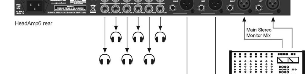
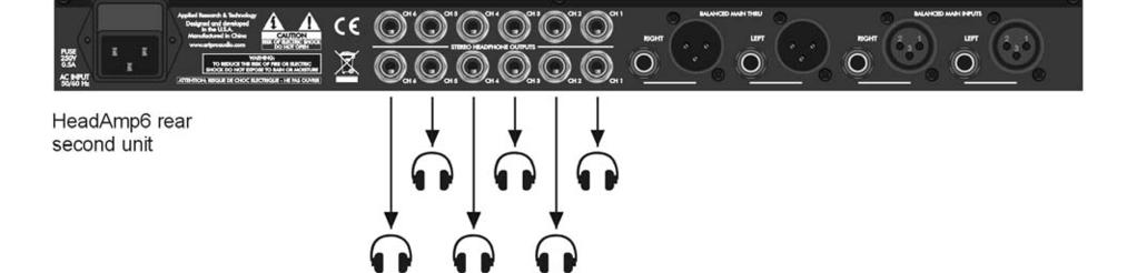
9 APPLICATIONS FIGURE 4 - Headphone Distribution Application 9
10 FIGURE 5 Block Diagram 10
11 WARRANTY INFORMATION Limited Warranty: Applied Research and Technology will provide warranty and service for this unit in accordance with the following warrants: Applied Research and Technology, (A R T) warrants to the original purchaser that this product and the components thereof will be free from defects in workmanship and materials for a period of three years from the date of purchase. Applied Research and Technology will, without charge, repair or replace, at its option, defective product or component parts upon prepaid delivery to the factory service department or authorized service center, accompanied by proof of purchase date in the form of a valid sales receipt. Exclusions: This warranty does not apply in the event of misuse or abuse of the product or as a result of unauthorized alterations or repairs. This warranty is void if the serial number is altered, defaced, or removed. A R T reserves the right to make changes in design or make additions to or improvements upon this product without any obligation to install the same on products previously manufactured. A R T shall not be liable for any consequential damages, including without limitation damages resulting from loss of use. Some states do not allow limitations of incidental or consequential damages, so the above limitation or exclusion may not apply to you. This warranty gives you specific rights and you may have other rights, which vary, from state to state. For units purchased outside the United States, an authorized distributor of Applied Research and Technology will provide service. SERVICE The following information is provided in the unlikely event that your unit requires service. 1) Be sure that the unit is the cause of the problem. Check to make sure the unit has power, all cables are connected correctly, and the cables themselves are in working condition. You may want to consult with your dealer for assistance in troubleshooting or testing your particular configuration. 2) If you believe the ART unit is at fault, go to You may contact Customer Service for more assistance, or directly request a Return Authorization for service in the resources area of the website. 3) If you are returning the unit for service, pack the unit in its original carton or a reasonable substitute. The original packaging may not be suitable as a shipping carton, so consider putting the packaged unit in another box for shipping. Print the RA number clearly on the outside of the shipping box. 4) Include, with your unit, a note with the RA number and your contact information including a daytime phone number, preferably attached to the top of the unit. Fill in the following information for your reference: Date of purchase Purchased from Serial number 11
12 HEADAMP6 SPECIFICATIONS Input Connections: XLR-F balanced (2), ¼-inch balanced (9) Output Connections: XLR-M balanced (2), ¼-inch balanced (2), ¼-inch stereo headphone (18) Input Impedance: 40K Ohms Main, 10K Ohms Direct, 15K Ohms Aux In Output Impedance: <12 Ohms Headphones Maximum Input Level: Maximum Output Level: +21dBu (all inputs) 150mW (600 Ohm Headphones) 500mW (32 Ohm Headphones) 150mW (8 Ohm Headphones) Maximum Gain: 22dB Signal to Noise Ratio: >90dB typical THD: <.01% typical Dynamic Range: >101dB typical CMRR: >40dB Phase Shift: <10 degrees, 20Hz - 20kHz Power Requirements: 120VAC / 50-60Hz, or 230VAC / 50 Hz, 15 Watts Dimensions: (HxWxD inch) 1.75 x 19 x 6 Dimensions: (HxWxD mm) 44.5 x 483 x 152 Weight: 5.3 lbs. (2.4kg) Ref: 0 dbu = 0.775VAC RMS ART maintains a policy of constant product improvement. ART reserves the right to make changes in design or make additions to or improvements upon this product without any obligation to install the same on products previously manufactured. Therefore, specifications are subject to change without notice. support@artproaudio.com 2010 Applied Research & Technology HA
PS8 - II. Professional Power Sequencer. User s Manual
 PS8 - II Professional Power Sequencer User s Manual IMPORTANT SAFETY INSTRUCTIONS READ FIRST This symbol, whenever it appears, alerts you to the presence of uninsulated dangerous voltage inside the enclosure.
PDS8u POWER DISTRIBUTION SYSTEM USER'S MANUAL
 PDS8u POWER DISTRIBUTION SYSTEM USER'S MANUAL 1 IMPORTANT SAFETY INSTRUCTION READ FIRST This symbol, whenever it appears, alerts you to the presence of uninsulated dangerous voltage inside the enclosure-voltage
Dual Channel Active Direct Box. Artcessories. User's Manual
 Dual Channel Active Direct Box Artcessories User's Manual IMPORTANT SAFETY INSTRUCTION READ FIRST This symbol, whenever it appears, alerts you to the presence of uninsulated dangerous voltage inside enclosure-voltage
Three Channel XLR Balanced Patch Bay. Artcessories. User's Manual
 Three Channel XLR Balanced Patch Bay Artcessories User's Manual IMPORTANT SAFETY INSTRUCTION READ FIRST This symbol, whenever it appears, alerts you to the presence of uninsulated dangerous voltage inside
Two Channel 48 Volt Phantom Power Supply. Artcessories. User's Manual
 Two Channel 48 Volt Phantom Power Supply Artcessories User's Manual IMPORTANT SAFETY INSTRUCTION READ FIRST This symbol, whenever it appears, alerts you to the presence of uninsulated dangerous voltage
USBMIX4. Project Series. User's Manual FOUR CHANNEL MIXER WITH USB INTERFACE
 USBMIX4 FOUR CHANNEL MIXER WITH USB INTERFACE Project Series User's Manual IMPORTANT SAFETY INSTRUCTIONS - READ FIRST This symbol, wherever it appears, alerts you to the presence of uninsulated dangerous
USBMIX6. Project Series
 USBMIX6 Six Channel Mic-Inst-Line Mixer - Computer Interface Project Series User s Manual IMPORTANT SAFETY INSTRUCTIONS - READ FIRST This symbol, wherever it appears, alerts you to the presence of uninsulated
PREMIUMAUDIOVIDEOLIGHTINGANDPOWERPRODUCTS
 FACTOR ELECTRONICS PREMIUMAUDIOVIDEOLIGHTINGANDPOWERPRODUCTS V-RVC Owners Manual IMPORTANT NOTE: THIS OWNER'S MANUAL IS PROVIDED AS AN INSTALLATION AND OPERATING AID. FACTOR ELECTRONICS DOES NOT ASSUME
PREMIUMAUDIOVIDEOANDPOWERPRODUCTS V-RVC-PRO. Owners Manual
 PREMIUMAUDIOVIDEOANDPOWERPRODUCTS V-RVC-PRO Owners Manual IMPORTANT NOTE: THIS OWNER'S MANUAL IS PROVIDED AS AN INSTALLATION AND OPERATING AID. FACTOR ELECTRONICS DOES NOT ASSUME ANY RESPONSIBILITY AS
Blonde On Blonde OWNER S MANUAL SWR SCOTTSDALE, AZ USA
 Blonde On Blonde OWNER S MANUAL SWR SCOTTSDALE, AZ USA IMPORTANT SAFETY INSTRUCTIONS CAUTION: TO REDUCE RISK OF ELECTRIC SHOCK, DO NOT REMOVE THE COVER OR BACK. NO USER-SERVICEABLE PARTS INSIDE. PLEASE
Users Manual. Pronomic TAS-18 Active Touring System
 Users Manual Pronomic TAS-18 Active Touring System Version 01/2012 IMPORTANT SAFETY INSTRUCTIONS The apparatus shall not be exposed to dripping or splashing and that no objects filled with liquids, such
CM-series compact mixing consoles. User Manual
 CM-series compact mixing consoles CM4-LIVE (170.800) CM4-STUDIO (170.810) CM6-LIVE (170.801) CM8-LIVE (170.802) CM8-STUDIO (170.812) CM10-LIVE (170.803) User Manual Features: 4 LIVE models with USB/SD
BS 181 SINGLE CHANNEL POWER SUPPLY USER MANUAL
 BS 181 SINGLE CHANNEL POWER SUPPLY USER MANUAL Issue 2011 ASL Intercom BV DESIGNED & MANUFACTURED BY: ASL Intercom B.V. Zonnebaan 42 3542 EG Utrecht The Netherlands Tel: +31 (0)30 2411901 Fax: +31 (0)30
TVA2.1 2-Channel Digital Amplifier Installation Manual
 TVA2.1 2-Channel Digital Amplifier Installation Manual SAFETY INSTRUCTIONS WARNING: TO REDUCE THE RISK OF FIRE OR ELECTRIC SHOCK, DO NOT EXPOSE THIS APPLIANCE TO RAIN OR MOISTURE. CAUTION: TO REDUCE THE
PCM60A 100W MAX P.A. AMPLIFIER.
 PCM60A 100W MAX P.A. AMPLIFIER www.pyleaudio.com IMPORTANT SAFETY INSTRUCTIONS 1. Read Instructions All the safety and operating instructions should be read before the appliance is operated. 2. Retain
HRS-1S. Half Rack Analog Stereo Audio Speaker Monitor. User Guide. Part Number , Revision E
 HRS-1S Half Rack Analog Stereo Audio Speaker Monitor User Guide Part Number 821535, Revision E 2012 Wohler Technologies, Inc. and PANORAMA. All rights reserved. This publication is protected by federal
BS 287 DUAL CHANNEL POWER SUPPLY. User Manual. January 2017 V1.0
 BS 287 DUAL CHANNEL POWER SUPPLY User Manual January 2017 V1.0 Table of contents 1.0 SAFETY INSTRUCTIONS... 3 2.0 GENERAL DESCRIPTION PS 289... 4 3.0 MECHANICAL INSTALLATION... 5 4.0 MAINS POWER & SAFETY
R290DS Dual Source Power Amplifier Installation Manual
 R290DS Dual Source Power Amplifier Installation Manual SAFETY INSTRUCTIONS WARNING: TO REDUCE THE RISK OF FIRE OR ELECTRIC SHOCK, DO NOT EXPOSE THIS APPLIANCE TO RAIN OR MOISTURE. CAUTION: TO REDUCE THE
PS 680 SIX CHANNEL POWER SUPPLY WITH AUX MATRIX USER MANUAL
 PS 680 SIX CHANNEL POWER SUPPLY WITH AUX MATRIX USER MANUAL Issue 2010 ASL Intercom BV DESIGNED AND MANUFACTURED BY: ASL INTERCOM B.V. ZONNEBAAN 42 3542 EG UTRECHT THE NETHERLANDS PHONE: +31 (0)30 2411901
PORTABLE WIRELESS PA SYSTEM WITH LITHIUM -ION RECHARGEABLE BATTERY AWP6042 OWNER S MANUAL. Handheld Microphone Headset Transmitter
 PORTABLE WIRELESS PA SYSTEM WITH LITHIUM -ION RECHARGEABLE BATTERY AWP6042 OWNER S MANUAL X1 Headset Microphone AWX6042H VHF Wireless Headset Transmitter Handheld Microphone Headset Transmitter Thank you
CM SERIES. Compact Live and Studio Mixers. Item ref: UK, UK, UK, UK, UK, UK User Manual
 CM SERIES Compact Live and Studio Mixers Item ref: 170.800UK, 170.801UK, 170.802UK, 170.803UK, 170.810UK, 170.812UK User Manual Caution: Please read this manual carefully before operating Damage caused
YST-SW20 SUBWOOFER SYSTEM OWNER S MANUAL. Active Servo Technology
 CAUTION SUBWOOFER SYSTEM Active Servo RISK OF ELECTRIC SHOCK DO NOT OPEN CAUTION: TO REDUCE THE RISK OF ELECTRIC SHOCK DO NOT REMOVE COVER (OR BACK). NO USER-SERVICEABLE PARTS SIDE. REFER SERVICG TO QUALIFIED
English MP210. Français. Multimedia Speaker. User Manual. Please read this manual carefully before operating the Speaker System
 Multimedia Speaker Français User Manual Please read this manual carefully before operating the Speaker System Introduction Congratulations on the purchase of the Edifier speaker system. With the right
Kogan Bluetooth Karaoke System with Dual Microphones KAKAR2MICA
 Kogan Bluetooth Karaoke System with Dual Microphones KAKAR2MICA K TABLE OF CONTENTS SAFETY & WARNINGS...1 IMPORTANT SAFETY INSTRUCTIONS...1 AC CONNECTION...2 LOCATION OF CONTROLS...3 ASSEMBLY AND CONNECTIONS...4
BS 181 SINGLE CHANNEL POWER SUPPLY USER MANUAL
 BS 181 SINGLE CHANNEL POWER SUPPLY USER MANUAL August 2016 This product is designed and manufactured by: ASL Intercom B.V. Zonnebaan 42 3542 EG Utrecht The Netherlands Phone: +31 (0)30 2411901 Fax: +31
BS 217 DUAL CHANNEL MASTER STATION USER MANUAL
 BS 217 DUAL CHANNEL MASTER STATION USER MANUAL August 2016 This product is designed and manufactured by: ASL Intercom B.V. Zonnebaan 42 3542 EG Utrecht The Netherlands Phone: +31 (0)30 2411901 Fax: +31
DA-816 USER GUIDE. Version 1.2 January Park Road Chanhassen, MN
 DA-816 USER GUIDE Version 1.2 January 2017 1266 Park Road Chanhassen, MN 55317 952-401-7700 support@digitalaudio.com www.digitalaudio.com SAFETY INSTRUCTIONS TO REDUCE THE RISK OF ELECTRIC SHOCK, DO NOT
SUBWOOFER SYSTEM YST-MSW10
 ACTIVE SERVO PROCESSING SUBWOOFER SYSTEM YST-MSW10 Active Servo SUBWOOFER SYSTEM YST-MSW10 Active Servo HIGH CUT HIGH LOW OWNER S MANUAL MANUAL DE INSTRUCCIONES CAUTION RISK OF ELECTRIC SHOCK DO NPT OPEN
T L Audio INDIGO SERIES. User Manual C-2021 VALVE COMPRESSOR. Tony Larking Professional Sales Limited, Letchworth, England.
 T L Audio INDIGO SERIES User Manual C-2021 VALVE COMPRESSOR Tony Larking Professional Sales Limited, Letchworth, England. Tel: 01462 490600. International +44 1462 490600. Fax: 01462 490700. International
PREMIUMAUDIOVIDEOANDPOWERPRODUCTS COMM-2 Two-Way Active Horn Speaker / Microphone System
 PREMIUMAUDIOVIDEOANDPOWERPRODUCTS COMM-2 Two-Way Active Horn Speaker / Microphone System Please read the terms of use below before using this product: This product has the ability to collect audio which
MP SERIES PROFESSIONAL POWER AMPLIFIER
 MP SERIES PROFESSIONAL POWER AMPLIFIER OPERATING MANUAL AND USER GUIDE www.wharfedalepro.com TABLE OF CONTENTS TABLE OF CONTENTS... 1 IMPORTANT WARNINGS & SAFETY INSTRUCTIONS... 2 INTRODUCTION... 3 ABOUT
CPD SERIES OPERATING MANUAL AND USER GUIDE. Professional Power Amplifier.
 CPD SERIES Professional Power Amplifier OPERATING MANUAL AND USER GUIDE www.wharfedalepro.com TABLE OF CONTENTS TABLE OF CONTENTS... 1 IMPORTANT WARNINGS & SAFETY INSTRUCTIONS... 2 INTRODUCTION... 3 ABOUT
PS 289 DUAL CHANNEL POWER SUPPLY USER MANUAL
 PS 289 DUAL CHANNEL POWER SUPPLY USER MANUAL August 2016 This product is designed and manufactured by: ASL Intercom B.V. Zonnebaan 42 3542 EG Utrecht The Netherlands Phone: +31 (0)30 2411901 Fax: + 31
P75 Dual Source Power Amplifier Installation Manual
 P75 Dual Source Power Amplifier Installation Manual SAFETY INSTRUCTIONS CAUTION: TO REDUCE THE RISK OF ELECTRIC SHOCK, DO NOT REMOVE THE COVER. NO USER- SERVICEABLE PARTS INSIDE. REFER SERVICING TO QUALIFIED
PRE116/126. User Manual.
 PRE116/126 User Manual www.audac.eu ADDITIONAL INFORMATION This manual is put together with much care, and is as complete as could be on the publication date. However, updates on the specifications, functionality
INTERPRETER CONTROL UNIT MODEL PL ICU 2 2 (2 INPUTS 2 OUTPUTS) INSTRUCTION MANUAL Technical Data Warranty Information
 INSTRUCTION MANUAL Technical Data Warranty Information") INTERPRETER CONTROL UNIT MODEL PL ICU 2 2 (2 INPUTS 2 OUTPUTS) INSTRUCTION MANUAL Technical Data Warranty Information 2 INTERPRETER CONTROL UNIT - MODEL PL ICU 2 2 INSTRUCTION MANUAL Congratulations on
INTERPRETER CONTROL UNIT MODEL PL ICU 2 2 (2 INPUTS 2 OUTPUTS) INSTRUCTION MANUAL Technical Data Warranty Information 2 INTERPRETER CONTROL UNIT - MODEL PL ICU 2 2 INSTRUCTION MANUAL Congratulations on
MODEL 805 USER MANUAL
 MODEL 805 USER MANUAL All Rights Reserved Page 1 of 12 UNPACKING & INSPECTION Save all packing materials they are required for returns and warranty service. Inspect the 805 and packing materials for any
T L Audio INDIGO SERIES. User Manual PA-2001 VALVE PRE-AMPLIFIER. Tony Larking Professional Sales Limited, Letchworth, England.
 T L Audio INDIGO SERIES User Manual PA-2001 VALVE PRE-AMPLIFIER Tony Larking Professional Sales Limited, Letchworth, England. Tel: 01462 490600. International +44 1462 490600. Fax: 01462 490700. International
MA V 30W Mixer Amplifier Order code: CRAM02 MA V 60W Mixer Amplifier Order code: CRAM03 USER MANUAL
 www.cleveracoustics.co.uk MA 130 100V 30W Mixer Amplifier Order code: CRAM02 MA 160 100V 60W Mixer Amplifier Order code: CRAM03 USER MANUAL WARNING FOR YOUR OWN SAFETY, PLEASE READ THIS USER MANUAL CAREFULLY
Marshall Electronics. AR-AM4-BG Analog Audio Monitor. Operating Instructions
 Marshall Electronics AR-AM4-BG Analog Audio Monitor Operating Instructions 1 2 This page left intentionally blank Contents Product Overview...5 Features...5 Installation and Initial Setup...5 Unpacking...
OWNER S MANUAL GEQ 131/ 131LF GEQ 215/ 215LF GEQ 231. Single Channel 31 Band Graphic Equalizer. 2 Channel 15 Band Graphic Equalizer
 20 25 31.5 40 50 63 80 0 125 160 200 250 315 400 500 630 800 1K 1.25K 1.6K 2K 2.5K 3.15K 4K 5K 6.3K 8K K 12.5K 16K 20K +12 +6 +3 0-3 GEQ 131LF 5 31 BAND GRAPHIC EQUALIZER 15 40 60 7K 15K 22K BYPASS RANGE
P125 Dual Source Power Amplifier Installation Manual
 P125 Dual Source Power Amplifier Installation Manual SAFETY INSTRUCTIONS WARNING: TO REDUCE THE RISK OF FIRE OR ELECTRIC SHOCK, DO NOT EXPOSE THIS APPLIANCE TO RAIN OR MOISTURE. CAUTION: TO REDUCE THE
INSTRUCTION MANUAL DISTRIBUTION UNIT. Please read this manual thoroughly before use, and keep it handy for future reference.
 INSTRUCTION MANUAL DISTRIBUTION UNIT Please read this manual thoroughly before use, and keep it handy for future reference. ISSUE 1 May 2006 LIMITATION OF LIABILITY THE INFORMATION IN THIS PUBLICATION
Cantata m100 Amplifier
 Cantata m100 Amplifier Getting Started Guide www.resolutionaudio.com +1.415.553.4100 Safety Information CAUTION RISK OF ELECTRICAL SHOCK DO NOT OPEN CAUTION: TO REDUCE THE RISK OF ELECTRICAL SHOCK, DO
FOOT CONTROLLER FCV100
 CV NORM OUTPUT2 OUTPUT1 MIN VOL 0 10 User Manual FOOT CONTROLLER FCV100 Ultra-Flexible Dual-Mode Foot Pedal for Volume and Modulation Control 2 FOOT CONTROLLER FCV100 User Manual Table of Contents Thank
C-300 Preamplifier User s guide
 C-300 Preamplifier User s guide C-300 Preamplifier User s guide Specifications: Contents: Output: Max 7.5Vrms unbalanced (RCA) or 15Vrms balanced (XLR) SPECIFICATIONS Page 2 Phono: istortion, line stage:
PS-20. Power Supply. User Manual Rev F
 PS-20 Power Supply User Manual 9350-6786-100 Rev F OCT 2009 PROPRIETARY NOTICE The product information and design disclosed herein were originated by and are the property of Bosch Security Systems, Inc.
XC4100 INSTALLATION/OWNER'S MANUAL AM/FM/Cassette Receiver
 XC4100 INSTALLATION/OWNER'S MANUAL AM/FM/Cassette Receiver Preparation XC4100 INSTALLATION Please read entire manual before installation. Before You Start Disconnect negative battery terminal. Consult
Marshall Electronics. AR-AM1 Analog Audio Monitor. Operating Instructions
 Marshall Electronics AR-AM1 Analog Audio Monitor 1 Operating Instructions 2 This page left intentionally blank Contents Product Overview...5 Features...5 Installation and Initial Setup...5 Unpacking...
Marshall Electronics. Operating Instructions. Warranty. AR-AM1 Analog Audio Monitor
 Warranty Marshall Electronics warranties to the first consumer that this AR-AM1 Audio Monitor will, under normal use, be free from defects in workmanship and materials, when received in its original container,
CM/CS SERIES. Compact 100V amplifiers. Item ref: UK, UK, UK User Manual. CM/CS Series User Manual
 CM/CS SERIES Compact 100V amplifiers Item ref: 953.100UK, 953.101UK, 953.102UK User Manual Caution: Please read this manual carefully before operating Damage caused by misuse is not covered by the warranty
VIDAR OWNER S MANUAL STEREO OR MONO POWER AMP NOW, THAT S NOT A HINT THAT A THOR AMP IS COMING.
 VIDAR STEREO OR MONO POWER AMP In Norse mythology, VIDAR WAS THE STRONGEST GOD BEHIND THOR. NOW, THAT S NOT A HINT THAT A THOR AMP IS COMING. WE PROBABLY WOULDN T SURVIVE THE COPYRIGHT LITIGATION. AND
Marshall Electronics. Operating Instructions. Warranty. AR-AM4 Analog Audio Monitor
 Warranty Marshall Electronics warranties to the first consumer that this AR-AM4 Audio Monitor will, under normal use, be free from defects in workmanship and materials, when received in its original container,
U-300 Unity Amplifier User s guide
 U-300 Unity Amplifier User s guide U-300 Unity Amplifier User s guide Specifications: Contents: Output: 2 x 300 W/8 Ohm, 2 x 600 W/4 Ohm SPECIFICATIONS Page 2 Distortion:
Ares. Modular Audiophile System. by Thrax Audio. Operating Manual. Manual issued 15/03/2018 CAUTION
 Ares Modular Audiophile System by Thrax Audio Operating Manual Manual issued 15/03/2018 CAUTION THE UNIT CONTAINS NO USER SERVICEABLE PARTS. DO NOT REMOVE THE COVERS. LETHAL VOLTAGES ARE PRESENT WITHIN
IMPORTANT SAFETY INSTRUCTIONS
 IMPORTANT SAFETY INSTRUCTIONS When using this electronic device, basic precautions should always be taken, including the following: 1. Read all instructions before using the product. 2. Do not use this
Compact USB Digital Speakers. Quick Start User Guide
 Compact USB Digital Speakers Quick Start User Guide Quick Start User Guide is also available on our website: www.ultralinkproducts.com/ucube This product is intended for use solely with the USB and RCA
OWNER S MANUAL CD-2 V 1.3
 OWNER S MANUAL CD-2 V 1.3 2 TABLE OF CONTENTS WARNINGS... 3 ACCESSORIES... 4 REMOTE CONTROL... 5 FRONT PANEL... 6 REAR PANEL... 7 MENU SYSTEM... 8 NOTES OF IMPORTANCE... 10 CONNECTORS... 11 TECHNICAL SPECIFICATIONS...
SAFETY WARNINGS AND GUIDLINES
 SAFETY WARNINGS AND GUIDLINES Do not expose this device to water or moisture of any kind. Do not place drinks or other containers with moisture on or near the device. If moisture does get in or on the
A Watt Stereo Amplifier
 A0240 40 Watt Stereo Amplifier 8 The A0240 is a 2-channel 40 Watt class D amplifier. It can be used to power a small 1-room audio system or integrated with Channel Vision s A0302 to provide supplemental
Operating Instruction Manual POWERED MIXER. Model MX-401. Toa Electric Co., Ltd. KOBE, JAPAN
 Operating Instruction Manual POWERED MIXER Model MX-401 Toa Electric Co., Ltd. KOBE, JAPAN Contents General Description Features Front Panel [Names of components & their usage] Rear Panel [Names of components
DI8E Operating Manual
 DI8E Operating Manual August 2012 SAFETY INSTRUCTIONS CAUTION: To reduce the risk of electrical shock, do not remove the cover or rear personnel only. WARNING: to rain or moisture. DETAILED SAFETY INSTRUCTIONS:
FOR FURTHER INFORMATION CONTACT: Music Hall 108 Station Road Great Neck, NY Tel: Fax:
 Guarantee This entitles you to have the music hall ph25.2 repaired or replaced, at our discretion, free of charge for one year after purchase, at any authorized music hall dealer, provided the unit was
Console Power Supply
 MPS12 Console Power Supply USER GUIDE Publication AP5739 Limited One Year Warranty This product has been manufactured in the UK by ALLEN & HEATH and is warranted to be free from defects in materials or
Audio. one CAT-5 EXT-DVI-1CAT5-SR. User Manual. Release A2
 Audio DVI 3GSDI ELR Lite Embedder Extender over one CAT-5 EXT-DVI-1CAT5-SR User Manual Release A2 DVI ELR Lite Extender over one CAT-5 Important Safety Instructions 1. Read these instructions. 2. Keep
und4o Four Output Dante /AES67 Break Out Interface User Manual Date 8/27/2018 Revision 02_d
 Four Output Dante /AES67 Break Out Interface Date 8/27/2018 Revision 02_d Attero Tech, LLC 1315 Directors Row, Suite 107, Ft Wayne, IN 46808 Phone 260-496-9668 Fax 260-496-9879 www.atterotech.com 614-00028
PMXU83BT. PMXU43BT - PMXU63BT - PMXU83BT Wireless BT Streaming Studio Mixer DJ Controller Audio Mixing Console System
 PMXUBT PMXU6BT PMXU8BT PMXUBT - PMXU6BT - PMXU8BT Wireless BT Streaming Studio Mixer DJ Controller Audio Mixing Console System TABLE OF CONTENTS Important Safety Instructions 1. Introduction General mixing
MPF-1, Mains Power Filter User Manual
 1/7 Important Safety Information 2/7 Protect the power cable from being walked on or pinched particularly at the plugs, convenience receptacles, and at the point where they exit from the apparatus. Refer
1 Mic-In / 1 Guitar-In, 2-Out Professional vocal recording USB Interface. User manual
 1 Mic-In / 1 Guitar-In, 2-Out Professional vocal recording USB Interface User manual Important Safety Instructions 1. Read this manual thoroughly before using this unit. 2. Keep this manual for future
V CHANNEL MODULAR PRE-AMP/MIXER V-9984 REMOTE INPUT MODULE V CHANNEL MODULAR PRE-AMP/MIXER
 Issue 1 V-9983 2 CHANNEL MODULAR PRE-AMP/MIXER V-9984 REMOTE INPUT MODULE V-9985 4 CHANNEL MODULAR PRE-AMP/MIXER INTRODUCTION These instructions contain the specifications and guidelines necessary to install,
SX2200 Series INSTALLATION INSTRUCTIONS. Electronic Systems Protection, Inc 8001 Knightdale Blvd. Suite 121 Knightdale NC 27545
 Electronic Systems Protection, Inc 8001 Knightdale Blvd. Suite 121 Knightdale NC 27545 SX2200 Series INSTALLATION INSTRUCTIONS IMPORTANT SAFETY INSTRUCTIONS WARNING: TO REDUCE THE RISK OF FIRE OR ELECTRIC
poly-planar Marine Audio System
 ME-52 Expansion Amplifier 1 ME-52 Expansion Amplifier Introduction: The ME-52 is a 2 channel audio amplifier capable of delivering up to 25W RMS per channel. It s compact, water resistant design allows
Owner s Manual. Isolate. Restore. Inspire! Power Conditioners Audio / Video Power Isolation Units Rack Mount / Consumer Series
 Owner s Manual 19 Pro Series Rack Mount (RK) Faceplate Isolate. 17 Consumer Series (C) Faceplate Available in Black (B) and Silver (S) Colours Restore. Power Conditioners Audio / Video Power Isolation
VOICE-ACTIVATED INTERCOM SYSTEM
 VOICE-ACTIVATED INTERCOM SYSTEM Owner s Manual For Wireless Intercom Model WHI-4CUPG EXPLANATION OF GRAPHIC WARNING SYMBOLS This symbol is intended to alert the user to the presence of un-insulated dangerous
M-1264 M-1212E STEREO MIXERS. TOA Corporation OPERATING INSTRUCTIONS. TOA 1000 series CAUTION
 OPERATING INSTRUCTIONS STEREO MIXERS M-1264 M-1212E TOA 1000 series CAUTION TO REDUCE THE RISK OF ELECTRICAL SHOCK, DO NOT REMOVE COVER. NO USER SERVICEABLE PARTS INSIDE. REFER SERVICING TO QUALIFIED SERVICE
PS 6379 Mk2 SIX CHANNEL MASTER SPEAKER STATION
 PS 6379 Mk2 SIX CHANNEL MASTER SPEAKER STATION USER MANUAL August 2016 This product is designed and manufactured by: ASL Intercom B.V. Zonnebaan 42, 3542 EG Utrecht The Netherlands Phone: +31 (0)30 2411901
AV-1600 DIGITAL AMPLIFIER OWNERS MANUAL
 AV-1600 DIGITAL AMPLIFIER OWNERS MANUAL www.visionaudiovisual.com/techaudio/av-1600 1 DECLARATION OF CONFORMITY Where applicable Vision products are certified and comply with all known local regulations
HP4 headphone amplifier. user manual
 HP4 headphone amplifier user manual Musikhaus Thomann Thomann GmbH Hans-Thomann-Straße 1 96138 Burgebrach Germany Telephone: +49 (0) 9546 9223-0 E-mail: info@thomann.de Internet: www.thomann.de 03.11.2015,
OLi POWA-5 Active Monitors
 Active Monitors User Manual : English Contents Important Information... 3 Front & Rear Panels... 4 Remote Control... 5 Connecting Your Speakers... 6 Bluetooth Function... 7 Use with ipod / MP3... 8 Use
Important Safety Instructions
 Important Safety Instructions The lightning flash with the arrowhead symbol within an equilateral triangle is intended to alert the user to the presence of dangerous voltage inside the product that may
SOUNDSTICKS WIRELESS. Setup Guide. Downloaded from
 SOUNDSTICKS WIRELESS Setup Guide English Japanese Simplified Chinese 2 SOUNDSTICKS WIRELESS 1. Read these instructions. 2. Keep these instructions. 3. Heed all warnings. 4. Follow all instructions. 5.
FOOT CONTROLLER FCV100. Quick Start Guide. Ultra-Flexible Dual-Mode Foot Pedal for Volume and Modulation Control
 CV NORM OUTPUT2 OUTPUT1 MIN VOL 0 10 Quick Start Guide (Check Out behringer.com for Full Manual) FOOT CONTROLLER FCV100 Ultra-Flexible Dual-Mode Foot Pedal for Volume and Modulation Control 2 FOOT CONTROLLER
2 Mic/1-Guitar in, 2 Line out recording USB Interface. User manual
 2 Mic/1-Guitar in, 2 Line out recording USB Interface User manual Important Safety Instructions 1. Read this manual thoroughly before using this unit. 2. Keep this manual for future reference. 3. Take
JuiceRack & JuiceBlock 500 series Power Supplies. Operating Manual V 1.1
 JuiceRack & JuiceBlock 500 series Power Supplies Operating Manual V 1.1 Contents 1 Safety instructions... 3 2 Foreword... 4 2.1 Important Notes:... 4 3 Introduction... 5 3.1 Setup... 5 3.2 Mains Voltage...
Operating instruction Manual POWERED MIXER. Model MX-101. Toa Electric Co., Ltd. KOBE, JAPAN
 Operating instruction Manual POWERED MIXER Model MX-101 Toa Electric Co., Ltd. KOBE, JAPAN Contents Precautions... 1 General Description... 2 Features... 2 Front Panel (Names of components & their usage)...
RX-2 OWNER S MANUAL INTRODUCTION TABLE OF CONTENT
 RX-2 OWNER S MANUAL INTRODUCTION The RX-2 is a networkable audio mixer for the mymix system. It is designed for remote configuration using the mymix Control interface. Like a mymix can it select audio
Sonneteer. Orton Integrated Amplifier
 Sonneteer Orton Integrated Amplifier Introduction Thank you for purchasing the new Sonneteer Orton integrated amplifier. For your safety and proper operation of your amplifier, please take time to read
MIX-16/MIX-32 USER GUIDE
 MIX-16/MIX-32 USER GUIDE Version 1.2 January 2017 1266 Park Road Chanhassen, MN 55317 952-401-7700 support@digitalaudio.com www.digitalaudio.com SAFETY STRUCTIONS TO REDUCE THE RISK OF ELECTRIC SHOCK,
DVI Detective. User Manual EXT-DVI-EDIDN. Release A3
 DVI Detective EXT-DVI-EDIDN User Manual Release A3 Important Safety Instructions 1. Read these instructions. 2. Keep these instructions. 3. Heed all warnings. 4. Follow all instructions. 5. Do not use
Dual Link DVI Extender
 2x Dual Link DVI Extender EXT-2DVI-CATDL User Manual Release A4 2x Dual Link DVI Extender Important Safety Instructions 1. Read these instructions. 2. Keep these instructions. 3. Heed all warnings. 4.
ACTIVE LOUDSPEAKER. Model: DJSP1216LBT
 ACTIVE LOUDSPEAKER Model: DJSP1216LBT PLEASE READ THIS USER MANUAL COMPLETELY BEFORE OPERATING THIS UNIT AND RETAIN THIS BOOKLET FOR FUTURE REFERENCE. WARNINGS To reduce the risk of fire or electric shock,
CANARY AUDIO. Vacuum Tube Compact Disc Player CD-100 OWNER S MANUAL. Handcrafted in California MADE IN USA
 CANARY AUDIO Vacuum Tube Compact Disc Player Handcrafted in California CD-100 OWNER S MANUAL MADE IN USA Dear Customer: Please allow us to take this opportunity to thank you for purchasing this CANARY
DVI KVM. Extra Long Range Extender Over One CAT5. User Manual EXT-DVIKVM-ELR. Release A8
 DVI KVM Extra Long Range Extender Over One CAT5 EXT-DVIKVM-ELR User Manual Release A8 Important Safety Instructions 1 Read these instructions 2 Keep these instructions 3 Heed all warnings 4 Follow all
2 CHANNEL, CLASS D AMPLIFIERS PA2X25 PA2X60 PA2X125 PA2X150. pulseaudio1.com vanco1.com
 2 CHANNEL, CLASS D AMPLIFIERS PA2X25 PA2X60 PA2X125 PA2X150 pulseaudio1.com vanco1.com 800.626.6445 DEAR CUSTOMER Thank you for purchasing this product. For optimum performance and safety, please read
User Guide. DMXSM-H18 Splitter. DMXSM-H81 Merger. Document Release Aug Revision B
 User Guide DMXSM-H18 Splitter DMXSM-H81 Merger Document Release Aug. 2008 Revision B Warranty Leviton Manufacturing Co Inc. warrants this device to be free of material and workmanship defects for a period
DM25, DM40. Compact 100V mixer-amplifiers with Bluetooth. Item ref: UK, UK User Manual
 DM25, DM40 Compact 100V mixer-amplifiers with Bluetooth Item ref: 953.108UK, 953.109UK User Manual Caution: Please read this manual carefully before operating Damage caused by misuse is not covered by
CANARY AUDIO CA-430. Vacuum Tube MM/MC Phono Preamplifier OWNER S MANUAL. Handcrafted in California MADE IN USA
 CANARY AUDIO Vacuum Tube MM/MC Phono Preamplifier Handcrafted in California CA-430 OWNER S MANUAL MADE IN USA Dear Customer: Please allow us to take this opportunity to thank you for purchasing this CANARY
Kramer Electronics, Ltd.
 Kramer Electronics, Ltd. Preliminary USER MANUAL Model: 903 Personal Stereo Amplifier Contents Contents 1 Introduction 1 2 Getting Started 1 2.1 Quick Start 2 3 Overview 3 4 Your 903 Personal Stereo Amplifier
IMPORTANT SAFETY INSTRUCTIONS. 7) Do not block any ventilation openings. Install in accordance with the manufacturer s instructions.
 Do not block any ventilation openings. Install in accordance with the manufacturer s instructions.") TEDDY stage monitor IMPORTANT SAFETY INSTRUCTIONS THE LIGHTNING FLASH WITH ARROWHEAD SYMBOL, WITHIN AN EQUILATERAL TRIANGLE, IS INTENDED TO ALERT THE USER TO THE PRESENCE OF UNINSULATED DANGEROUS VOLTAGE
TEDDY stage monitor IMPORTANT SAFETY INSTRUCTIONS THE LIGHTNING FLASH WITH ARROWHEAD SYMBOL, WITHIN AN EQUILATERAL TRIANGLE, IS INTENDED TO ALERT THE USER TO THE PRESENCE OF UNINSULATED DANGEROUS VOLTAGE
BlueKeeper. Wireless Audio Gateway. User Guide. JK Audio
 BlueKeeper Wireless Audio Gateway User Guide JK Audio Introduction JK Audio combines Bluetooth* Wireless Technology with professional audio electronics in a convenient desktop design. BlueKeeper pairs