A Control System Plant Simulator
|
|
|
- Conrad Crawford
- 6 years ago
- Views:
Transcription
1 A Control System Plant Simulator utilizing the mbed NXP LPC1768 Microcontroller For: NXP mbed Design Challenge Sponsors: NXP/mbed/Elektor/Circuit Cellar Date: February 28, 2011 By: NXP-3892
2 Motivation There are many tools available to the engineer to assist them with the analysis, design and tuning of control systems. Many of these tools are specially designed software packages to model the controller and plant. In some cases, they create virtual solutions without coming in contact with actual hardware. These methods use assumptions and software to create nice solutions at your desk. They most likely will need to be tweaked or perhaps redone when they are combined with the actual system components such as a controller, sensors and actuators. One difficulty with this approach is the lack of understanding of the true characteristics of the plant. Along with this, the software solution doesn t answer the question of how the controller components will interface to the plant. Another concern is that sometimes the characteristics of the sensors will play a role in the overall solution. Three-mode or PID controllers are very common in industry today because of their low cost and ease of applicability. They seem to be the first choice of application toward a solution and work well when the system is rather simple. What happens when parameters start to vary with time or change relative to other parameters such as temperature or pressure? Do we retune? Do we use gain scheduling, or perhaps do we use a system that is adaptive? Do we use a more complicated control strategy? If we had a better understanding of the plant dynamics or process characteristics we could explore other possibilities in the lab instead of at the customers expense. Furthermore, at some point during the development phase of a control system, the control strategy will need to be ported into the controller and tested against the actual plant. If the actual plant is not available because it has not yet been built, could we just use software to simulate the plant? The answer is NO. We can simulate the overall control/plant system using software tools but the control strategy warrants testing and debug when the final program is loaded into the target hardware. The project may not have enough time allocated to accomplish this. If there were a piece of hardware available that interconnects and interacts with the controller that can simulate the plant/process operation, this would allow you to test the overall system in a shorter time and place you much closer to the finish line with a higher level of confidence. The mbed rapid prototyping tool for micro-controllers is an excellent way of creating an actual platform to simulate a process or plant that is to be controlled. In this approach, the engineer will use data acquisition to gather information about the plant or process and use it to derive an approximate model that can be used to develop a controller and/or control strategy. Once a physical plant model has been attained, the engineer can use it to asses different types of controls that are necessary to achieve their objectives. The control system can be tested in the laboratory under changing parameters (temperature, pressure, flow, etc.) and not during a time the customer is trying to maintain production.

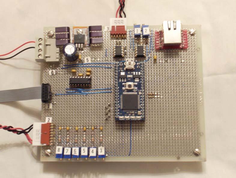
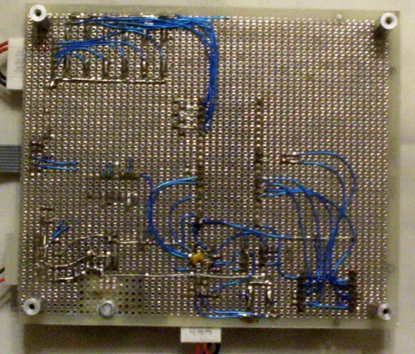
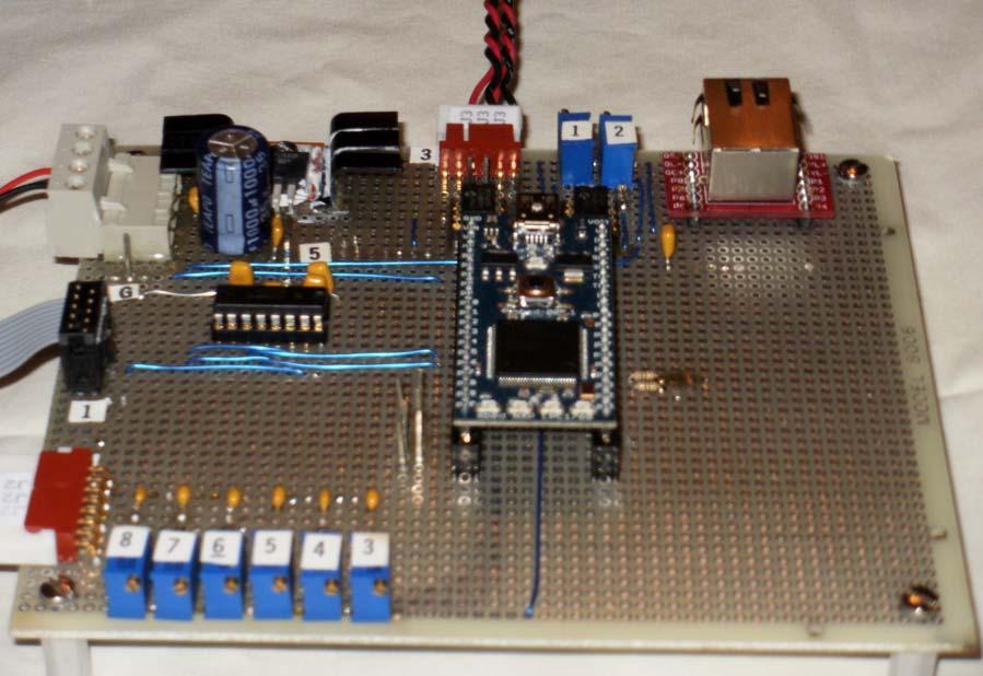
3 This idea of creating an actual piece of hardware that simulates the plant can allow you to test the controller and achieve with absolute certainty that your control strategies will work and the system will interface to the plant without any surprises. Hardware The NXP mbed design challenge hosted by Circuit Cellar provided an opportunity to take a look at a really great prototyping platform, the mbed NXP1768. This small micro-controller board is based on the ARM Cortex-M3 operating at a speed of 96MHz with 512K bytes of Flash memory and 64K of RAM. The mbed design places the ARM processor on a 40-pin DIP package with 0.1 spacing and a 0.9 width. The mbed board is designed to plug directly into a solderless breadboard. I chose a Futuelec protoboard to house the circuitry for this project. The mbed board hosts a load of interfaces including: (2) SPI ports, (3) serial ports, (2) I2C ports, (6) Analog inputs, (1) analog output, (6) PWM outputs, (1) CAN, (1) Ethernet and (1) USB interfaces. (26) of the pins may be used as bidirectional digital I/O. The board can be powered through the USB connection or by an external voltage source in the range of 4.5 to 9V. The mbed microcontroller board is the heart of this project but provides quite a punch at a low cost for any project. The pin-out shown below shows the capabilities of the microcontroller board. It can be found on the website: A visit to this website will immediately get you hooked on this great product.
4 Below is a block diagram of the circuit build to host this application. This block diagram along with a schematic for the system and bill of material may be found in the appendix of this paper. The example that I used to explain this idea uses only two analog inputs and a single analog output. I have added the Microchip MCP4822 to provide an additional two analog output using the SPI bus. Below is a brief description for each element of the system. ANALOG INPUTS I wired all (6) of the analog inputs to the mbed micro-controller board to a connector in the event that a more complex process involving multiple inputs is to be simulated. In this example only two inputs were considered. AI0 is used to accept the command signal from the controller. The second analog input can be used to simulate the effects on the plant for changes in temperature. Providing an analog signal on this input can simulate this condition.. ANALOG OUTPUT The Plant Simulator uses two analog outputs. Analog Output channel 1 is the simulated transducer output with a range of 0-6V. The pressure transducer being simulated has a range of 1-6VDC. Analog Output channel 2 is used to monitor the systems dynamic response with a scope. It is adjusted to have a 0-10V range. As a future note, this second output can also be used to simulate a plant with two outputs if need be.
5 This system uses one of the two SPI ports available from the mbed package. Pins 5, 7 and 8 provide the MOSI, SCK and SSEL signals necessary for a SPI device to operate. The Microchip MCP-4822 is a 12 bit SPI input DAC chip that is used to produce a 0-5V output with a code input on both channels. Each channel uses ½ of a Microchip TC913A op-amp package. Both amplifiers can provide a gain of up to 3.3 and are both adjustable, DIGITAL INPUTS Digital Input at pin P21 was used to assist with testing when the software was being written. When this input is brought low, It forces a step function to be loaded into the input array. It can be used but serves as no other purpose. SERIAL PORT One of the three serial ports of the mbed controller is used with this simulator. Pins P9 and P10 perform transmit and receive functions that are used to communicate with a PC running a terminal emulator program for command control entry and data extraction. Since the system has no display or keyboard, all communications are implemented through the serial port. Hyperterminal (bundled with windows XP) was used in the development of this system. ETHERNET INTERFACE The Ethernet interface has been included on the schematic for this project and was wired but is not used for the simulator. I had a lot of fun working with the Ethernet interface with all of its capabilities but decided that I didn t have enough knowledge to make it work well. Since MBED is a great learning tool, I was able to gain some knowledge in this area. Software The Plant/Process Simulator doesn t have a display or keyboard. All communication with the system is done over the serial interface. A buffered, interrupt based serial driver that has been made available on the mbed.org website by developer Andy Kirkham of the United Kingdom was used in this application (Thank You Andy). Getting the serial interface functioning was very easy once the driver was setup. The application was slightly modified to support the simulator. The main program is shown below in flowchart form. When the MAIN program starts its execution, the first tasks to occur are: SPI port is initialized Variables are initialized The TIC Handler is detached Pull up resistor for DIN is enabled
6 A display is written to the PC connected to the serial port indicating the program has been started and is ready for command entry. A prompt for HELP is also displayed. The system waits for a command to be entered. If a message is sent from the serial port, it will be processed by a call to the messageprocess () subroutine. This can be seen in the block diagram. The main program will also interacts with the TIC handler which calls the plant() subroutine and the acquisition function. When a plant simulation runs, the system will put data into two arrays: the input array U[] and the output array Y[]. These arrays are 2000 points each. They are circular in that there is no beginning or end. The TIC handler is launched when the command RUN is executed. The commands will be explained in a later section of this report. If the RUN command is not executed, the system waits indefinitely for a command to be entered, When the command is given to RUN the simulation, the RUN_FLAG is set. The main program watches to see if an acquisition is requested. If no acquisition is requested, the main program does nothing. The system will continue to run the simulation in the background. When the ACQ command is entered, the system will start to acquire data. The circular array pointer ia is saved in ACQ_Index. This marks the beginning of the acquisition record. During this time, the main program simply monitors the event and keeps track of when a valid data record is stored; then count is incremented. The acquisition is complete when (count > samplesize-1). Upon completion, a file is opened and data is written starting at the ACQ_Index pointer until the number of requested records is saved (samplesize). After data has been written, the file is closed and the ACQ_Start flag is cleared.
7
8 Using the System Connect the serial port of the system to a PC using a strait though cable. Any terminal emulator program may be used to setup the interface. I used Hyperterminal (bundled with window XP) for the development of this system. After hitting the reset pushbutton or powering the sytem up, you will see the following prompt: NXP mbed Design Challange Date: 28-Feb-2011 By: NPX-3892 CONTROL SYSTEM PROCESS/PLANT SIMULATOR HELP or? for command listing Typing the HELP command or the? followed by a <CR> will show the following screen.? PLANT SIMULATOR - Help > Commands are single line. > Commands may be issued upper/lower case. RUN Start the Simulation. STOP Stop the Simuation. ACQ Acquire N-Samples of INPUT/OUTPUT data from the simulation. Stores data in file "data.txt" on the MBED flash. POST Sends the Acquired data out the serial port. SAVE Saves Parameters in file "PARM.txt" on the MBed flash. LOAD Loads the Parameters from file "PARM.txt" on the MBed flash. AOCAL Calibrate the Analog Output Amplifiers (both channels) AICAL Calibrate the Analog Input Channels ACH0 and ACH1. AORAMP Generate (1Hz) sawtooth ramps out Aout-A(increasing slope) and Aout-B (decreasing slope). TF Demonstrates the Transfer between Analog Input and Analog Output. HELP/? Send this help file out the serial port. SET Sets the Simulation Parameters. Ts - Sample Rate (ms) Kp - Plant Gain Tp - Plant Time Constant (ms) 0p - Delay (ms) N - Acquisition Sample Size Example: SET: Ts=100 Each command will have a dialog screen. The following gives information on what each command means.
9 COMMAND LIST RUN Typing RUN you will get the prompt: Simulation Has Started! This indicates that the simulation has STARTED. You may start an acquisition only after the simulation has begun. STOP Typing the STOP command, you will get the prompt: Simulation Has Stopped! This indicates that the simulation has STOPPED. You cannot acquire data when the simulation is not running. ACQ If you type ACQ when the simulation is not running, you will get the following messge: Cannot Acquire Data!!! Simulation did not start...use RUN command to start simulation. If you started the simulation and then typed ACQ, the message will be: Collecting 1000 samples Indicating that 1000 samples will be acquired then save to the data file data.txt on the local drive. The file may be posted to the serial port and collected using Hyperterminal.
10 POST When you type the POST command, the system will dump the file named data.txt out the serial port. You can capture the text file using Hyperterminal. The prompt will be: Writing Data out Serial Port Lots of data in here Post Complete!!! SAVE After the command SAVE is typed, the system will save all parameters to the file parm.txt located on the local drive of the mbed board. The file is in flat ascii fomat. Saving parameters to the file parm.txt Parameters Saved!!! LOAD After typing the LOAD command, the system will attempt to load the parm.txt file if it is present on the local drive. If the file is present, the prompt will be: Loading parameters from the file parm.txt Parameters Loaded!!! If the file doesn t exist on the local drive, the prompt will be: Loading parameters from the file parm.txt File cannot be opened (may not exist)!!!
11 HELP/? Typing either HELP or? will yield the following results: PLANT SIMULATOR - Help > Commands are single line. > Commands may be issued upper/lower case. RUN STOP ACQ POST SAVE LOAD AOCAL AICAL AORAMP TF HELP/? SET Start the Simulation. Stop the Simuation. Acquire N-Samples of INPUT/OUTPUT data from the simulation. Stores data in file "data.txt" on the MBED flash. Sends the Acquired data out the serial port. Saves Parameters in file "PARM.txt" on the MBed flash. Loads the Parameters from file "PARM.txt" on the MBed flash. Calibrate the Analog Output Amplifiers (both channels) Calibrate the Analog Input Channels ACH0 and ACH1. Generate (1Hz) sawtooth ramps out Aout-A(increasing slope) and Aout-B (decreasing slope). Demonstrates the Transfer between Analog Input and Analog Output. Send this help file out the serial port. Sets the Simulation Parameters. Ts - Sample Rate (ms) Kp - Plant Gain Tp - Plant Time Constant (ms) 0p - Delay (ms) N - Acquisition Sample Size Example: SET: Ts=100 SET Typing the SET command will allow you to set the internal parameters. The parameters are: Ts - Sample time limit in ms. Kp - Plant gain Tp - Plant time constant in ms. Op - Plant Dead time in ms. N - Number of samples to take As and example typing the following will yield: set:ts=10 Setting Parameters: Ts=10(ms)
12 The last four commands are used to set the adjustments on the Plant/Process simulator board. The first two commands allow you to trim the Analog Output amplifier (op-amps), the Analog Input attenuation networks. The third command generates a ramp out both of the analog ports. While the last command transfers the voltage from channels Ain0 to Aout0 and Ain1 to Aout1. AOCAL Typing the AOCAL command yields: Calibrate DAC Outputs: Both DAC's are set to a 4095 count input. Trim output amplifier to desired maximum level (10V). DACOut0 = 4095 DACOut1= 4095 AICAL Typing the AICAL yields the following prompt: AICAL Calibrate ADC Inputs ACH0 and ACH1: Set the input signal to 10V. Then adjust SPAN pots RP3 and RP4 to display 0xFFFF for each channel. Press <ENTER> key to end test. ACH0f = ACH0i = 0 ACH1f = ACH1i = 0 AORAMP Typing the AORAMP command caused the system to generate analog ramps. This dialog is: Aoramp Generate 1Hz Ramp Signals out both Analog Ports. Aout-A (Positive Ramp) Aout-B (Negative Ramp). Press <ENTER> key to end test. DACOut0 = 3960 DACOut1= 1464 TF Typing the TF command yields the following: TF Read Analog input channels ACH0 and ACH1. Transfer these values to Analog Output channels Aout-A and Aout-B. Press <ENTER> key to end test. ACH0i = 0 ACH1i = 0
13 Test Results The next four graphs show the results of running the simulator and collecting data for the conditions that were discovered using the data acquisition process presented at the beginning of this paper. The curves below show the results of simulations for changing the speed of the motor 20%, 30%, 40% and 50%. They may have slightly different Kp values than the actual values.
14
15
Laboratory: Introduction to Mechatronics. Instructor TA: Edgar Martinez Soberanes Lab 1.
 Laboratory: Introduction to Mechatronics Instructor TA: Edgar Martinez Soberanes (eem370@mail.usask.ca) 2017-01-12 Lab 1. Introduction Lab Sessions Lab 1. Introduction to the equipment and tools to be
I2C and SPI Foundation
 Revision 30 September 2010 Release I2C and SPI Foundation 17 March 2018 changed ref: command f to x Introduction I2C (I squared C) and SPI (Serial peripheral Interface) are two main ways that microcontrollers
RDB1768 Development Board User Manual
 RDB1768 Development Board User Manual 6/16/2009 Rev.2 Copyright Code Red Technologies Inc. 2009 Page 1 of 18 1 OVERVIEW 3 1.1 LPC1768 Features 3 1.2 RDB1768 Evaluation Board Hardware 3 2 COMPONENTS 5 2.1
mbed Hello World! Introduction to mbed
 mbed Hello World 1 Agenda Introduction to mbed Lab 1: mbed registration and Hello World demo Lab 2: Other IO Lab 3: Interfacing with sensors Lab 4: Output devices, a TextLCD Lab 5: Rapid prototyping, Build
An Arduino Controlled 1 Hz to 60 MHz Signal Generator
 An Arduino Controlled 1 Hz to 60 MHz Signal Generator Greg McIntire, AA5C AA5C@arrl.net WWW..ORG 1 Objectives Build a standalone 60 MHz signal generator based on the DDS-60 board. Originally controlled
Group 10 Programmable Sensor Output Simulator Progress Report #2
 Department of Electrical Engineering University of Victoria ELEC 499 Design Project Group 10 Programmable Sensor Output Simulator Progress Report #2 March 5, 2005 Submitted by: Group No.: 10 Team: Exfour
Description Building Automation Platform ARM mbed and Arduino
 MPN MAXREFDES130 Description Building Automation Platform ARM mbed and Arduino MAXREFDES130# is an Arduino form-factor shield compatible with ARM mbed and Arduino platforms providing a complete reference
Chapter 2: Introducing the mbed tw rev
 Chapter 2: Introducing the mbed tw rev. 26.8.16 If you use or reference these slides or the associated textbook, please cite the original authors work as follows: Toulson, R. & Wilmshurst, T. (2016). Fast
CONTENTS. dspicpro4 KEY FEATURES 4 CONNECTING THE SYSTEM 5 INTRODUCTION 6
 CONTENTS dspicpro4 KEY FEATURES 4 CONNECTING THE SYSTEM 5 INTRODUCTION 6 Switches and Jumpers 7 MCU Sockets 8 Power Supply 10 On-Board USB 2.0 Programmer 11 MikroICD 12 RS-232 Communication Circuit 13
MicroBolt. Microcomputer/Controller Featuring the Philips LPC2106 FEATURES
 Microcomputer/Controller Featuring the Philips LPC2106 FEATURES Powerful 60 MHz, 32-bit ARM processing core. Pin compatible with 24 pin Stamp-like controllers. Small size complete computer/controller with
TNG-3B derives its operating power from the serial port. The DTR, RTS, and both data lines are all used, and must be properly connected.
 TNG-3B FAQ December 4, 2004 1. What s a TNG? TNG is pronounced thing as in The Cat in the Hat by Dr. Seuss, and stands for totally neat gadget. TNG-3B is the third in an evolutionary line of simple data
PIC Serial Peripheral Interface (SPI) to Digital Pot
 to Digital Pot") Name Lab Section PIC Serial Peripheral Interface (SPI) to Digital Pot Lab 7 Introduction: SPI is a popular synchronous serial communication protocol that allows ICs to communicate over short distances
Name Lab Section PIC Serial Peripheral Interface (SPI) to Digital Pot Lab 7 Introduction: SPI is a popular synchronous serial communication protocol that allows ICs to communicate over short distances
Microcontrollers. Principles and Applications. Ajit Pal +5 V 2K 8. 8 bit dip switch. P2 8 Reset switch Microcontroller AT89S52 100E +5 V. 2.
 Ajit Pal Microcontrollers Principles and Applications +5 V 2K 8 8 bit dip switch P2 8 Reset switch Microcontroller AT89S52 100E +5 V +5 V 2.2K 10 uf RST 7 Segment common anode LEDs P1(0-6) & P3(0-6) 7
MAXSANTAFEEVSYS User Manual
 MAXSANTAFEEVSYS User Manual Rev 0; 5/14 For pricing, delivery, and ordering information, please contact Maxim Direct at 1-888-629-4642, or visit Maxim Integrated s website at www.maximintegrated.com. Maxim
Arduino Uno R3 INTRODUCTION
 Arduino Uno R3 INTRODUCTION Arduino is used for building different types of electronic circuits easily using of both a physical programmable circuit board usually microcontroller and piece of code running
Project Abstract. (VI)sualizer: A Smart Electronic Load. An instrument for profiling solar, chemical, and grid-powered energy delivery devices
sualizer: A Smart Electronic Load. An instrument for profiling solar, chemical, and grid-powered energy delivery devices") Project Abstract (VI)sualizer: A Smart Electronic Load An instrument for profiling solar, chemical, and grid-powered energy delivery devices Entry # NXP3767 Submitted to Circuit Cellar for The NXP mbed
Project Abstract (VI)sualizer: A Smart Electronic Load An instrument for profiling solar, chemical, and grid-powered energy delivery devices Entry # NXP3767 Submitted to Circuit Cellar for The NXP mbed
Overview of Microcontroller and Embedded Systems
 UNIT-III Overview of Microcontroller and Embedded Systems Embedded Hardware and Various Building Blocks: The basic hardware components of an embedded system shown in a block diagram in below figure. These
Gooligum Electronics 2015
 The Wombat Prototyping Board for Raspberry Pi Operation and Software Guide This prototyping board is intended to make it easy to experiment and try out ideas for building electronic devices that connect
User Manual. LPC-StickView V3.0. for LPC-Stick (LPC2468) LPC2478-Stick LPC3250-Stick. Contents
 LPC2478-Stick LPC3250-Stick. Contents") User Manual LPC-StickView V3.0 for LPC-Stick (LPC2468) LPC2478-Stick LPC3250-Stick Contents 1 What is the LPC-Stick? 2 2 System Components 2 3 Installation 3 4 Updates 3 5 Starting the LPC-Stick View Software
User Manual LPC-StickView V3.0 for LPC-Stick (LPC2468) LPC2478-Stick LPC3250-Stick Contents 1 What is the LPC-Stick? 2 2 System Components 2 3 Installation 3 4 Updates 3 5 Starting the LPC-Stick View Software
Development of a MATLAB Data Acquisition and Control Toolbox for PIC Microcontrollers
 Chapter 3 Development of a MATLAB Data Acquisition and Control Toolbox for PIC Microcontrollers 3.1. Introduction Data acquisition and control boards (DACBs) are essential for interfacing sensors/actuators
AMS 5812 OEM pressure sensor with an analog and digital output
 Digital signal conditioning is becoming increasingly common in sensor technology. However, some sensor system states can be monitored more easily using analog values. For redundancy and system safety reasons
eip-24/100 Embedded TCP/IP 10/100-BaseT Network Module Features Description Applications
 Embedded TCP/IP 10/100-BaseT Network Module Features 16-bit Microcontroller with Enhanced Flash program memory and static RAM data memory On board 10/100Mbps Ethernet controller, and RJ45 jack for network
I2C-AI418S I2C Bus Voltage and Current Analog Input Board
 I2C-AI48 I2C Bus Voltage and Current Analog Input Board Features 4 Channels Of Analog Inputs MCP3424, 2,4,6 and 8-Bit Voltage Input: -5V, -V Current Input: -2mA, 4-2mA, -4mA I2C Bus Interface Khz, 4Khz,
DSP Research Project
 DSP Research Project The digital signal processing (DSP) research project is a core component of the Physics 351 digital electronics course. The research project component is structured as design, construction,
Advanced Debugging I. Equipment Required. Preliminary Discussion. Basic System Bring-up. Hardware Bring-up, Section Plan
 Advanced Debugging I Hardware Bring-up, Section Plan Equipment Required 192 car Logic analyzer with mini probes, cable PC scope with probes, M-F breadboard wire, USB cable Voltmeter Laptop with mouse,
1/Build a Mintronics: MintDuino
 1/Build a Mintronics: The is perfect for anyone interested in learning (or teaching) the fundamentals of how micro controllers work. It will have you building your own micro controller from scratch on
Product Overview -A 16 bit Micro Experimenter for Solderless Breadboards
 Product Overview -A 16 bit Micro Experimenter for Solderless Breadboards 1.0 Introduction The 16 Bit Micro Experimenter is an innovative solderless breadboard kit solution developed by a Microchip Academic
The industrial technology is rapidly moving towards ARM based solutions. Keeping this in mind, we are providing a Embedded ARM Training Suite.
 EMBEDDED ARM TRAINING SUITE ARM SUITE INCLUDES ARM 7 TRAINER KIT COMPILER AND DEBUGGER THROUGH JTAG INTERFACE PROJECT DEVELOPMENT SOLUTION FOR ARM 7 e-linux LAB FOR ARM 9 TRAINING PROGRAM INTRODUCTION
THE LPC84X MCU FAMILY A MULTI-TESTER TOOL OFFERING FEATURES FOR YOUR NEXT IOT DESIGN
 THE LPC84X MCU FAMILY A MULTI-TESTER TOOL OFFERING FEATURES FOR YOUR NEXT IOT DESIGN KEVIN TOWNSEND (MICROBUILDER) BRENDON SLADE (NXP) Agenda Part I Overview of the LPC84x Multi-Tester Swiss army knife
EZ-Bv4 Datasheet v0.7
 EZ-Bv4 Datasheet v0.7 Table of Contents Introduction... 2 Electrical Characteristics... 3 Regulated and Unregulated Power Pins... 4 Low Battery Warning... 4 Hardware Features Main CPU... 5 Fuse Protection...
Introduction to MATLABs Data Acquisition Toolbox, the USB DAQ, and accelerometers
 Introduction to MATLABs Data Acquisition Toolbox, the USB DAQ, and accelerometers This week we will start to learn the software that we will use through the course, MATLAB s Data Acquisition Toolbox. This
DEVELOPMENT OF USER FRIENDLY DATA ACQUISITION AND ACTUATION SYSTEM ON EMBEDDED PLATFORM
 DEVELOPMENT OF USER FRIENDLY DATA ACQUISITION AND ACTUATION SYSTEM ON EMBEDDED PLATFORM 1 Moolya Ashwar Shankar, 2 Mr. Sukesh Rao M. 1 PG Scholar, 2 Assistant Professor, NMAMIT Nitte Email: 1 moolya.ashwar@gmail.com,
CSE 466 Exam 1 Winter, 2010
 This take-home exam has 100 points and is due at the beginning of class on Friday, Feb. 13. (!!!) Please submit printed output if possible. Otherwise, write legibly. Both the Word document and the PDF
SECTION 1 INTRODUCTION. Walt Kester
 SECTION 1 INTRODUCTION Walt Kester This book deals with sensors and associated signal conditioning circuits. The topic is broad, but the focus of this book is to concentrate on circuit and signal processing
PRACTICAL DESIGN TECHNIQUES FOR SENSOR SIGNAL CONDITIONING
 9 PRACTICAL DESIGN TECHNIQUES FOR SENSOR SIGNAL CONDITIONING 1 Introduction 2 Bridge Circuits 3 Amplifiers for Signal Conditioning 4 Strain, Force, Pressure, and Flow Measurements 5 High Impedance Sensors
ECE 189A Senior Capstone December 16, 2014 Team Leader: Will Miller Charles Crain, Isaac Flores, Brian Phan, Sarah Pilkington
 ECE 189A Senior Capstone December 16, 2014 Team Leader: Will Miller Charles Crain, Isaac Flores, Brian Phan, Sarah Pilkington Agenda Project Overview Parts Power Distribution Schematic and Bill of Materials
CORRIGENDUM ISSUED FOR NATIONAL COMPETITIVE BIDDING UNDER TEQIP PHASE-II
 CORRIGENDUM ISSUED FOR NATIONAL COMPETITIVE BIDDING UNDER TEQIP PHASE-II The prebid meeting for the packages to be purchased under national competitive bidding for TEQIP Phase II was held on 15/10/2013
Lab 01 Arduino 程式設計實驗. Essential Arduino Programming and Digital Signal Process
 Lab 01 Arduino 程式設計實驗 Essential Arduino Programming and Digital Signal Process Arduino Arduino is an open-source electronics prototyping platform based on flexible, easy-to-use hardware and software. It's
Layad Circuits Arduino Basic Kit B. Content Summary
 Layad Circuits This kit is a careful selection of sensors, displays, modules, an Arduino Uno, connectors and other essential parts meant to facilitate learning of the hardware and software components of
Downloaded from Elcodis.com electronic components distributor
 CONTENTS LV24-33A KEY FEATURES 4 CONNECTING THE SYSTEM 5 INTRODUCTION 6 Switches and Jumpers 7 MCU Sockets 8 Power Supply 10 On-board USB 2.0 Programmer 11 RS-232 Communication Circuit 12 LEDs 14 Push
MT2 Introduction Embedded Systems. MT2.1 Mechatronic systems
 MT2 Introduction Embedded Systems MT2.1 Mechatronic systems Mechatronics is the synergistic integration of mechanical engineering, with electronics and intelligent computer control in the design and manufacturing
University Program Advance Material
 University Program Advance Material Advance Material Modules Introduction ti to C8051F360 Analog Performance Measurement (ADC and DAC) Detailed overview of system variances, parameters (offset, gain, linearity)
Unlocking the Potential of Your Microcontroller
 Unlocking the Potential of Your Microcontroller Ethan Wu Storming Robots, Branchburg NJ, USA Abstract. Many useful hardware features of advanced microcontrollers are often not utilized to their fullest
Prototyping Module Datasheet
 Prototyping Module Datasheet Part Numbers: MPROTO100 rev 002 Zenseio LLC Updated: September 2016 Table of Contents Table of Contents Functional description PROTOTYPING MODULE OVERVIEW FEATURES BLOCK DIAGRAM
BIG8051. Development system. User manual
 BIG8051 User manual All s development systems represent irreplaceable tools for programming and developing microcontroller-based devices. Carefully chosen components and the use of machines of the last
SANKALCHAND PATEL COLLEGE OF ENGINEERING, VISNAGAR. ELECTRONICS & COMMUNICATION DEPARTMENT Question Bank- 1
 SANKALCHAND PATEL COLLEGE OF ENGINEERING, VISNAGAR ELECTRONICS & COMMUNICATION DEPARTMENT Question Bank- 1 Subject: Microcontroller and Interfacing (151001) Class: B.E.Sem V (EC-I & II) Q-1 Explain RISC
BV511 Hardware Guide ByVac ByVac Revision 1.0
 BV511 Hardware Guide ByVac ByVac 2007 www.byvac.co.uk Revision 1.0 ByVac 1 Copyright in this work is vested in ByVac and the document is issued in confidence for the purpose only for which it is supplied.
Freedom FRDM-KV31F Development Platform User s Guide
 Freescale Semiconductor, Inc. Document Number: FRDMKV31FUG User's Guide 0, 02/2016 Freedom FRDM-KV31F Development Platform User s Guide 1. Introduction The Freedom development platform is a set of software
ARDUINO BOARD LINE UP
 Technical Specifications Pinout Diagrams Technical Comparison Board Name Processor Operating/Input Voltage CPU Speed Analog In/Out Digital IO/PWM USB UART 101 Intel Curie 3.3 V/ 7-12V 32MHz 6/0 14/4 Regular
Anadigm FPAA Solutions Training Class III
 Anadigm FPAA Solutions Training Class III Agenda Learning Goals Evaluation board components Board architecture Power connection COM connection Output connection Development board Verify proper connection
Trends in Prototyping Systems. ni logic Pvt. Ltd., Pune, India
 Trends in Prototyping Systems ni logic Pvt. Ltd., Pune, India Focus of design dept. Electronic system & Flow Design problems Educating design Prototype USDP Features Applications Conclusion Agenda Faster
THE MICROCOMPUTER SYSTEM CHAPTER - 2
 THE MICROCOMPUTER SYSTEM CHAPTER - 2 20 2.1 GENERAL ASPECTS The first computer was developed using vacuum tubes. The computers thus developed were clumsy and dissipating more power. After the invention
D115 The Fast Optimal Servo Amplifier For Brush, Brushless, Voice Coil Servo Motors
 D115 The Fast Optimal Servo Amplifier For Brush, Brushless, Voice Coil Servo Motors Ron Boe 5/15/2014 This user guide details the servo drives capabilities and physical interfaces. Users will be able to
Laboratory of Sensors Engineering Sciences 9 CFU
 Laboratory of Sensors Engineering Sciences 9 CFU Contacts Alexandro Catini catini@ing.uniroma2.it Phone: +39 06 7259 7347 Department of Electronic Engineering First Floor - Room B1-07b Course Outline THEORY
ECE 471 Embedded Systems Lecture 2
 ECE 471 Embedded Systems Lecture 2 Vince Weaver http://web.eece.maine.edu/~vweaver vincent.weaver@maine.edu 7 September 2018 Announcements Reminder: The class notes are posted to the website. HW#1 will
EMCP 4.4 Simulator Manual. Author: Lucas Tolbert CIC Engineering 345 Center Street East Peoria, IL
 EMCP 4.4 Simulator Manual Author: Lucas Tolbert CIC Engineering 345 Center Street East Peoria, IL Date of Origin: 11/23/2010 Overview This document will detail the features and operation of the EMCP 4.4
Computer Hardware Requirements for Real-Time Applications
 Lecture (4) Computer Hardware Requirements for Real-Time Applications Prof. Kasim M. Al-Aubidy Computer Engineering Department Philadelphia University Real-Time Systems, Prof. Kasim Al-Aubidy 1 Lecture
Betrouwbare Elektronica ontwerpen en Produceren
 Betrouwbare Elektronica ontwerpen en Produceren Verbeter betrouwbaarheid, time to market en winstgevendheid met boundary scan JTAG Technologies B.V. Rik Doorneweert rik@jtag.com Boundary scan Testing HW
Introducing the 32 bit Micro Experimenter
 Introducing the 32 bit Micro Experimenter In a 2010, Nuts and Volts introduced the 16 bit Micro Experimenter with a seven article series. The 16 bit Experimenter offered the readership a new and significant
Wireless OBD II CAN Bus Embedded System Design
 Wireless OBD II CAN Bus Embedded System Design Carmen Bovalino January 2014 Table of Contents Objective... 1 Background... 1 Description of Proposal... 2 System Operation... 3 System Requirements... 3
Goal: We want to build an autonomous vehicle (robot)
") Goal: We want to build an autonomous vehicle (robot) This means it will have to think for itself, its going to need a brain Our robot s brain will be a tiny computer called a microcontroller Specifically
Goal: We want to build an autonomous vehicle (robot) This means it will have to think for itself, its going to need a brain Our robot s brain will be a tiny computer called a microcontroller Specifically
Embedded Development Platform
 Embedded Development Platform Getting Started Guide for the ARM mbed Carrier Module EDP-CM-mbed Version 3.11 February 2011 Contents 1. Introduction 3 2. Prepare to run the Hello World Program 4 2.1 Software
Embedded Systems Lab Lab 1 Introduction to Microcontrollers Eng. Dalia A. Awad
 Embedded Systems Lab Lab 1 Introduction to Microcontrollers Eng. Dalia A. Awad Objectives To be familiar with microcontrollers, PIC18F4550 microcontroller. Tools PIC18F4550 Microcontroller, MPLAB software,
SUB-SYSTEM BOARD 5562 Campbell (MAXREFDES4#): 16-Bit High-Accuracy 4-20mA Input Isolated Analog Front End (AFE)
: 16-Bit High-Accuracy 4-20mA Input Isolated Analog Front End (AFE)") Maxim > Design Support > Technical Documents > Sub-System Boards > APP 5562 Keywords: Campbell, MAXREFDES4, subsystem reference design, analog front end, AFE, industrial sensors, isolated power and data,
Maxim > Design Support > Technical Documents > Sub-System Boards > APP 5562 Keywords: Campbell, MAXREFDES4, subsystem reference design, analog front end, AFE, industrial sensors, isolated power and data,
Mechatronics and Measurement. Lecturer:Dung-An Wang Lecture 6
 Mechatronics and Measurement Lecturer:Dung-An Wang Lecture 6 Lecture outline Reading:Ch7 of text Today s lecture: Microcontroller 2 7.1 MICROPROCESSORS Hardware solution: consists of a selection of specific
Design Document. May Logging DC Wattmeter. Team Member: Advisor : Ailing Mei. Collin Christy. Andrew Kom. Client: Chongli Cai
 Design Document May13-06 Logging DC Wattmeter Team Member: Ailing Mei Andrew Kom Chongli Cai David Hoffman Advisor : Collin Christy Client: Garmin International Qiaoya Cui 0 Table of Contents EXECUTIVE
Project Number: P15452
 Multidisciplinary Senior Design Conference Kate Gleason College of Engineering Rochester Institute of Technology Rochester, New York 14623 Project Number: P15452 DATA ACQUISITION DEVICE Kyle Smith Electrical
Development of a digital instrument as a motivational component in teaching embedded computers
 Development of a digital instrument as a motivational component in teaching embedded computers Gracián Triviño 1, Felipe Fernández 2 1 Universidad Politécnica, Madrid, Spain, gtrivino@fi.upm.es 2 Universidad
DFI 7000 DIGITAL FORCE INDICATOR USER S GUIDE 1.0 INTRODUCTION 2.0 DESCRIPTION. 2.1 Configuration. 2.2 Specifications
 DFI 7000 DIGITAL FORCE INDICATOR USER S GUIDE 1.0 INTRODUCTION The DFI 7000 Signal Conditioner-Indicator is a complete 4-1/2-digit signal conditioner and indicator housed in a 1/8 DIN case. This unit provides
C:\Users\jacob\Documents\MtSAC\ELEC74 Mt SAC - chipkit\homework Sheets.docx
 ELEC 74 Worksheet 1 Logic Gate Review 1. Draw the truth table and schematic symbol for: a. An AND gate b. An OR gate c. An XOR gate d. A NOT gate ELEC74 Worksheet 2 (Number Systems) 1. Convert the following
EMBEDDED SYSTEMS: Jonathan W. Valvano INTRODUCTION TO THE MSP432 MICROCONTROLLER. Volume 1 First Edition June 2015
 EMBEDDED SYSTEMS: INTRODUCTION TO THE MSP432 MICROCONTROLLER Volume 1 First Edition June 2015 Jonathan W. Valvano ii Jonathan Valvano First edition 3 rd printing June 2015 The true engineering experience
Pic24f Family Reference Manual Section 14. Timers
 Pic24f Family Reference Manual Section 14. Timers Get Started Here 8-bit Peripheral Summary, Timers. Timers, Timer 0 (TMR0). Timer 0 For more information about the oscillator failure trap, refer to "Section
Wall Industries SMPS and Microcontrollers
 Wall Industries SMPS and Microcontrollers Introduction Wall Industries commitment to the latest technologies is evident in its recent announcement to add microcontrollers to their already advanced designs.
An open source, modular, robotic control system for building 3D printers, CNC routers, and other robotics applications
 JuicyBoard An open source, modular, robotic control system for building 3D printers, CNC routers, and other robotics applications Overview JuicyBoard is the foundation of a modular, open source platform
Multifunction Controller less STN LCD Software Library and Reference Hardware
 Multifunction Controller less STN LCD Software Library and Reference Hardware Abstract: mbed LPC1768 Model When an embedded device needs to convey much information to its user, the use of a graphic LCD
Introduction to PoliArd
 Introduction to PoliArd Damiano Milani Politecnico di Milano Department of Mechanical Engineering PoliArd Project PoliArd is a complete environment for implementing control logics on real-time hardware.
HZX N03 Bluetooth 4.0 Low Energy Module Datasheet
 HZX-51822-16N03 Bluetooth 4.0 Low Energy Module Datasheet SHEN ZHEN HUAZHIXIN TECHNOLOGY LTD 2017.7 NAME : Bluetooth 4.0 Low Energy Module MODEL NO. : HZX-51822-16N03 VERSION : V1.0 1.Revision History
MTRX3700 Mechatronics
 MTRX3700 Mechatronics 3 2015 PIC18F452 Software Exercises David Rye You are to work in a group of two students to write, debug and demonstrate a series of small assembly language and C programs that meet
ARDUINO MICRO WITHOUT HEADERS Code: A000093
 ARDUINO MICRO WITHOUT HEADERS Code: A000093 Arduino Micro is the smallest board of the family, easy to integrate it in everyday objects to make them interactive. The Micro is based on the ATmega32U4 microcontroller
Lecture 5: Computing Platforms. Asbjørn Djupdal ARM Norway, IDI NTNU 2013 TDT
 1 Lecture 5: Computing Platforms Asbjørn Djupdal ARM Norway, IDI NTNU 2013 2 Lecture overview Bus based systems Timing diagrams Bus protocols Various busses Basic I/O devices RAM Custom logic FPGA Debug
DSP Research Project
 DSP Research Project The digital signal processing (DSP) research project is a core component of the Physics 351 digital electronics course. The research project component is structured as design, construction,
Freescale Semiconductor Inc. Microcontroller Solutions Group. FRDM-KL46Z User s Manual FRDM-KL46Z-UM Rev. 1.0
 Freescale Semiconductor Inc. Microcontroller Solutions Group FRDM-KL46Z User s Manual FRDM-KL46Z-UM Rev. 1.0 Table of Contents 1 FRDM-KL46Z Overview... 3 2 References documents... 3 3 Getting started...
突破 8-/16-/32- 位和 DSP 界限的 ARM MCU 解决方案
 突破 8-/16-/32- 位和 DSP 界限的 ARM MCU 解决方案 BL Microcontrollers BU HPMS Jul 28 th, 2010 NXP Semiconductors NXP Semiconductors provides High Performance Mixed Signal and Standard Product solutions that leverage
MAXREFDES24EVSYS User Manual
 MAXREFDES24EVSYS User Manual Rev 1; 1/15 ADCLITE2 ANALOG SIGNAL CAPTURE GUI Windows PC REFDES24 4-CHANNEL ANALOG OUTPUT GUI 20 30VDC (>150mA) MAXREFDES24 MAX1659 LDO MAX17498 FLYBACK CONTROL MAX6126 VREF
Part Number: PCB-STM32-F4B1 (unpopulated PCB with Discovery module sockets, no other parts) STM32-F4B1 (assembled board, not presently available)
 STM32-F4B1 (assembled board, not presently available)") PCB-STM32-F4B1 Development baseboard for the STMicro Discovery-F4 module (STMicro part# STM32F4DISCOVERY) PCB Rev 1.00 shown. PCB Rev 1.20 has on-board RS232 drivers. Part Number: PCB-STM32-F4B1 (unpopulated
PCB-STM32-F4B1 Development baseboard for the STMicro Discovery-F4 module (STMicro part# STM32F4DISCOVERY) PCB Rev 1.00 shown. PCB Rev 1.20 has on-board RS232 drivers. Part Number: PCB-STM32-F4B1 (unpopulated
Adafruit Metro Mini. Created by lady ada. Last updated on :12:28 PM UTC
 Adafruit Metro Mini Created by lady ada Last updated on 2018-01-24 08:12:28 PM UTC Guide Contents Guide Contents Overview Pinouts USB & Serial converter Microcontroller & Crystal LEDs Power Pins & Regulators
DESIGN OF A CUBESAT PAYLOAD INTERFACE. Jason Axelson Department of Electrical Engineering University of Hawai i at Mānoa Honolulu, HI ABSTRACT
 DESIGN OF A CUBESAT PAYLOAD INTERFACE Jason Axelson Department of Electrical Engineering University of Hawai i at Mānoa Honolulu, HI 96822 ABSTRACT Typically, a complete satellite will be designed around
CMS-8GP32. A Motorola MC68HC908GP32 Microcontroller Board. xiom anufacturing
 CMS-8GP32 A Motorola MC68HC908GP32 Microcontroller Board xiom anufacturing 2000 717 Lingco Dr., Suite 209 Richardson, TX 75081 (972) 994-9676 FAX (972) 994-9170 email: Gary@axman.com web: http://www.axman.com
User Manual. LPC-StickView V1.1. for LPC-Stick. Contents
 User Manual LPC-StickView V1.1 for LPC-Stick Contents 1 What is LPC-Stick? 2 2 System Components 2 3 Installation 2 4 Updates 3 5 Starting the LPC-Stick View Software 4 6 Operating the LPC-Stick 6 7 Start
ME 3210: Mechatronics Signal Conditioning Circuit for IR Sensors March 27, 2003
 ME 3210: Mechatronics Signal Conditioning Circuit for IR Sensors March 27, 2003 This manual and the circuit described have been brought to you by Adam Blankespoor, Roy Merril, and the number 47. The Problem:
HC12 Built-In Hardware
 HC12 Built-In Hardware The HC12 has a number of useful pieces of hardware built into the chip. Different versions of the HC12 have slightly different pieces of hardware. We are using the MC68HC912B32 chip
Table of Contents. Introductory Material
 Table of Contents Introductory Material 0.1 Equipment Intoduction 1 breadboard area stimulator board 2 The Board of Education The TDS 340 oscilloscope 0.2 Getting Started with the Micro-controller The
Intel Galileo gen 2 Board
 Intel Galileo gen 2 Board The Arduino Intel Galileo board is a microcontroller board based on the Intel Quark SoC X1000, a 32- bit Intel Pentium -class system on a chip (SoC). It is the first board based
DEV-1 HamStack Development Board
 Sierra Radio Systems DEV-1 HamStack Development Board Reference Manual Version 1.0 Contents Introduction Hardware Compiler overview Program structure Code examples Sample projects For more information,
Introducting Itsy Bitsy 32u4
 Introducting Itsy Bitsy 32u4 Created by lady ada Last updated on 2018-01-03 05:47:20 AM UTC Guide Contents Guide Contents Overview Pinouts Which do you have? Power Pins Adafruit Pro Trinket LiIon/LiPoly
Programming in the MAXQ environment
 AVAILABLE The in-circuit debugging and program-loading features of the MAXQ2000 microcontroller combine with IAR s Embedded Workbench development environment to provide C or assembly-level application
K10 Intrinsically Safe Electro-Pneumatic Positioner Operating Manual
 K0 Intrinsically Safe Electro-Pneumatic Positioner Operating Manual Pneumatic Connection Single Acting Actuator (Spring Return): For single acting actuators Outlet Port 2 is to be plugged. Outlet Port
Introduction to L.A.P. 1
 Introduction to L.A.P. 1 Corrado Santoro ARSLAB - Autonomous and Robotic Systems Laboratory Dipartimento di Matematica e Informatica - Università di Catania, Italy santoro@dmi.unict.it L.A.P. 1 Course
Real Time Operating Systems Application Board Details
 Real Time Operating Systems Application Board Details Hardware Interface All labs involve writing a C program to generate an interface between a PC and an external Multi-Applications board. A 40-way ribbon
Chapter 5 - Input / Output
 Chapter 5 - Input / Output Luis Tarrataca luis.tarrataca@gmail.com CEFET-RJ L. Tarrataca Chapter 5 - Input / Output 1 / 90 1 Motivation 2 Principle of I/O Hardware I/O Devices Device Controllers Memory-Mapped