cytrynka PDB User Guide for power distribution board for zmr/qav/rcx 250 class copters
|
|
|
- Lucy Walters
- 6 years ago
- Views:
Transcription


1 cytrynka PDB User Guide for power distribution board for zmr/qav/rcx 250 class copters 1
2 Contents 1. Overview and future list 2. Installation 3. Hardware on board 4. Conversion board pins 5. Jumpers
3 WARNING! Read this manual very carefully before you start installation of our PDB. Incorrect use may result in fully damage of product, personal property and cause of serious injury. Operating with current over 60A may damage PDB! This is high degree complexity hobby product and operating it requires some basic mechanical and electrical abilities. Some parts on board may get hot. Don't touch any electronic components when in operation. Never connect conductive elements from top to bottom of board as this may cause of short circuit. 3
4 1. overview and future list Overview cytrynka PDB is a power distribution board designed for ZMR, QAV or RCX 250 size frames. It was created because I terribly hate clutter in cables. It's provides to use direct connections for most of popular FC on market (naze32, CC3D, flip32 etc) because it using conversion boards. Also on naze32 CB [conversion board] are OSD with compatibility of minim and kv team software and openlrs (openlrsng software). Future list fits ZMR250, QAV250 and RCX250 frames fits with most popular FC on market 1.6mm thickness with 70um copper current metter (90A) high lumen's LED's on front and back pins for minimosd direct connection with user selectable serial port number (UART1 or UART2) pins for UART1 or UART2 (GPS, external telemetry etc) pads for all ESC's and main battery low-pass PI filter (800mA maximum current) for FPV elements PWM to analog converter (RC) for radio link RSSI 5V/1.5A voltage regulator pads for radio link, video supply (filtered) on board buzzer 4

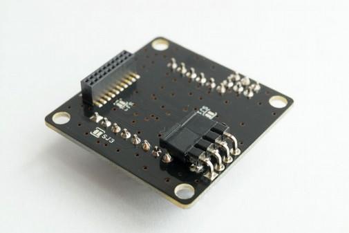
5 2. installation Prepare cytrynka PDB comes completely soldered and you don't need to solder nothing out of wires for battery, ESC, FPV (OSD including). Also, if you have not ordered CB for CC3D with wires you need to solder it. Installation We recommending to use spacers between bottom plate and our PDB to get best ventilation. If you use minimosd is recommended to solder it on beginning. PDB is prepared to use minimosd without soldered pins. If you have minim like this on photo you must remove all pins. Components must be on top. If not minimosd tie VIN and VOUT pins on minim video in/out connectors. Install battery leads with proper gauge for the amount of current you plan on running. Check two times polarity of battery connectors and pads on PDB. When soldering ESC's wires to PDB also pay attention with polarity. Install frame spacer (for top plate). Remember to use nylon screws (attached in package with cytrynka PDB). Now you can connect PDB with arms and main bottom plate (our PDB replace top bottom plate). 5
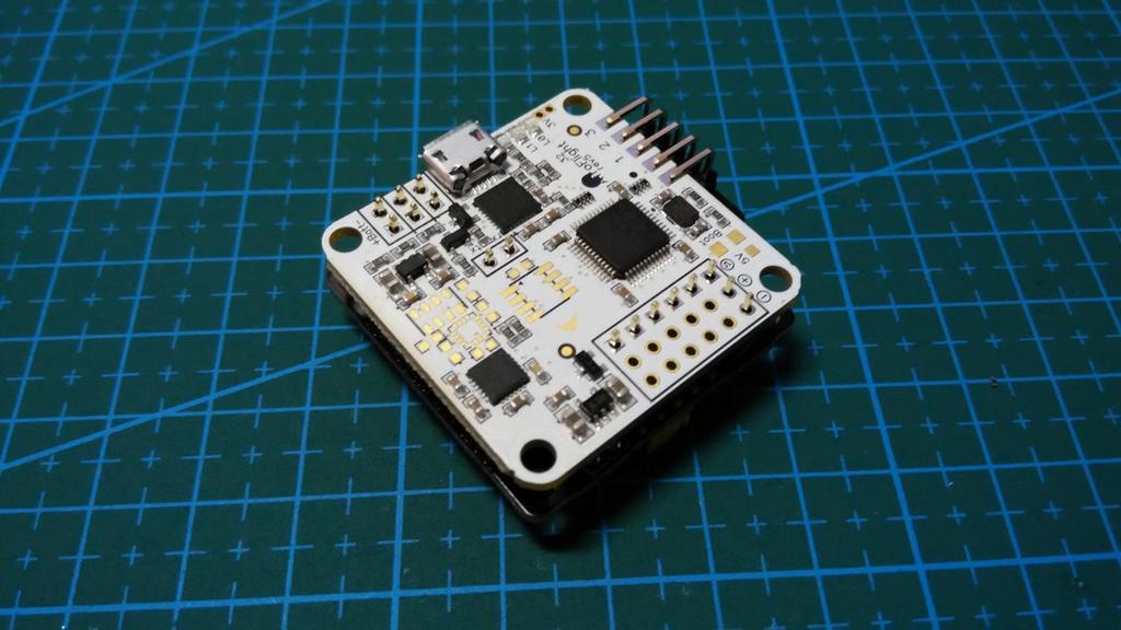
6 WARNING: Never cut pins directly on FC. This may destroy your gyro. Don't ask why just don't do it Flight controller installation naze32 Using naze32 flight controller with our cytrynka PDB is the best and easiest choice. User must only solder pins on naze and Conversion Board, connect it together with PDB, setup in configuration and fly. Just remember to solder pins on bottom side. Angled pins for PWM outputs must be a little bit prepared before soldering. Longer side of pins must be shortened about 2mm. WARNING: Remember to change the orientation in baseflight or cleanflight by entering the following: set align_board_yaw = 90 save Don't forget to check that all the movements are right in the GUI! If you made a mistake and the movements are not right, your quad will crash!! 6

7 FLIP32(+) FLIP32(+) flight controller is very similar to NAZE32 and installation is almost the same. Just remember to solder pins on bottom side. Angled pins for PWM outputs must be a little bit prepared before soldering. Longer side of pins must be shortened about 2mm. WARNING: Remember to change the board orientation in baseflight or cleanflight in yaw axis! 7
.")
8 CC3D CC3D best working with cytrynka PDB when it flashed with latest cleanflight firmware but it can work with Openpilot software with some limitations (no voltage, current and RSSI reading). Picture I: Cable colors for CC3D 8
9 PORT / CC3D Color Conversion Board Nr / PAD Signal name Receiver / White cppm / 1 PPM Receiver / Blue ss tx / 2 Software serial 1 TX pin Receiver / Yellow ss rx / 3 Software serial 1 RX pin Receiver / Green current / 4 Current measure pin Receiver / Orange vbat/ 5 Battery Voltage sensor Receiver / Purple rssi / 6 RSSI PORT / CC3D Color Conversion Board PAD Signal name Main and Flexi / Blue tx UART1/3 TX pad Main and Flexi / Orange rx UART1/3 RX pad CC3D Conversion Board have default installed 3.3V regulator for Spektrum Satellite with JST 1.5mm pitch connector, key transistor for buzzer and resistor voltage divider for battery voltage measurement. WARNING: All of CC3D's on market are with soldered PINS. Before using it with cytrynka PDB you must desolder it. It's not simple. Best solution is to remove first plastics from pins and after that removing pins one by one. Motors wiring with OP and Cleanflight firmware CL and OP have different motor mixing nonetheless in both firmwares user can define motors mixing but on CB we added jumpers for define which firmware you using. CC3D Buzzer usage with Openpilot and Cleanflight Information about using buzzer with CC3D with OP firmware can be found here: Before you must solder jumper Buzzer off on CB. With Cleanflight info about buzzer can be found here: Don't solder (or desolder) jumper Buzzer off on CB. 9
10 3. hardware on board Linear 5V UBEC cytrynka PDB has an on board 5V linear regulator with maximum current output 1.5A. It necessary for powering FC, minimosd or other OSD board, some FPV cameras and transmitters, GPS and programmable LED's. Also on board are pads for connection UBEC on one of ESC's and by solder jumper user can chose 5V source (internal or external not both). EXTERNAL 5V UBEC SOLDER PAD 5V SOURCE Radio link input pads and RSSI signal converter On board are solder pads (RSSI, PPM, 5V, RxD, GND) for RC direct connection. Our PDB for direct connection accepts only PPM sum signal and if your receiver does not operate with PPM you must use PWM to PPM converter or connect receiver to FC (or you can use Spektrum Satellite connecting it direct to CB connector). RxD pad is dedicated for FRSKY telemetry. RSSI signal have PWM to analog RC like this: RSSI from converter goes to CB and to solder pad and this can be used to connect it directly to minimosd (bypassing FC). 10
11 RC receiver solder pads 11
.")
12 Current meter cytrynka PDB has default on board current sensor with amperage up to 90A. WARNING: Current meter can work with amperage up to 90A but PDB is designed to carry current only up to 60A. There are two ways to get current value: soldering wire to pad on PDB and directly to OSD. In this case is not possible to log current value using FC (default connection PDB->CB). In this case user must activate feature in cleanflight configurator: on image above in Scale the output... is 400 but must be 815! or via CLI using commands: feature CURRENT_METER current_meter_type = 1 current_meter_scale = 815 current_meter_offset = 0 12


13 minimosd connector With our PDB is possible to install minimosd directly on board. For this purpose under the FC are pads to solder pins. WARNING: Before soldering minim on PDB select desired serial port number through solder jumpers. We recommending use UART2. See below. MinimOSD can be directly programed with UART2/1 (depending on selected serial port) connectors on PDB using FTDI programmer. OSD DTR is connected to RESET line on minim. If is used other OSD like minim (or with not compatible pinout) short selected pins on PDB. Solder jumpers for serial ports selecting for minim. For UART2 solder like this: For UART1 solder like this: 13


14 WARNING: Minim used for the cytrynka PDB must have a 5V modification. See below or check the link: For some minims 5V mod needs only shorting this pads: 14
.")
15 Video and LC filtered 12V For those who wants fly FPV on board are a LC filtered 12V power supply for camera and video transmitter and video IN/OUT solder pads. LED diodes On front and back of PDB are LED diodes- green on front, red on back. All of this are connected to 12V line. This is simple diodes (not WS2812B or similar). To switch off lights just remove LED OFF jumper. 15

16 4. conversion board pins Pins soldering on conversion boards Below are photos with correct soldered pins on conversion board for NAZE32 and FLIP32. Please pay attention to the angle connectors and jumpers. Naze32 16


17 FLIP32(+) 17
18 5. jumpers jumpers on PDB (main board) LED OFF - jumper for switching off/on led's on front and back (parallel with goldpin 2x1), SJ6 solder jumper on bottom side. This is for closing LC filter circuit when step-down regulator is not installed. With step-down must be open! SJ2, SJ3 jumper for Current Sensor and RSSI signals. Must be close! 5V SOURCE - with this jumper you can select 5V source (internal UBEC or external with input on pad on M1 connector) jumpers on NAZE32 conversion board SJ5 selection for UART port number for Spektrum satellite receiver (UART1 or UART2) SJ1 for S.BUS inverter activation jumpers on FLIP32(+) conversion board SJ2 always open SJ1 for S.BUS inverter activation SJ3 FRSKY input on softserial jumpers on CC3D conversion board solder jumpers group on bottom this jumpers are for motor mixing selection dependig firmware on CC3D (OP- openpilot, CF- cleanflight) Buzzer - closing circuit for buzzer output on SERVO channel (with transistor key). 18

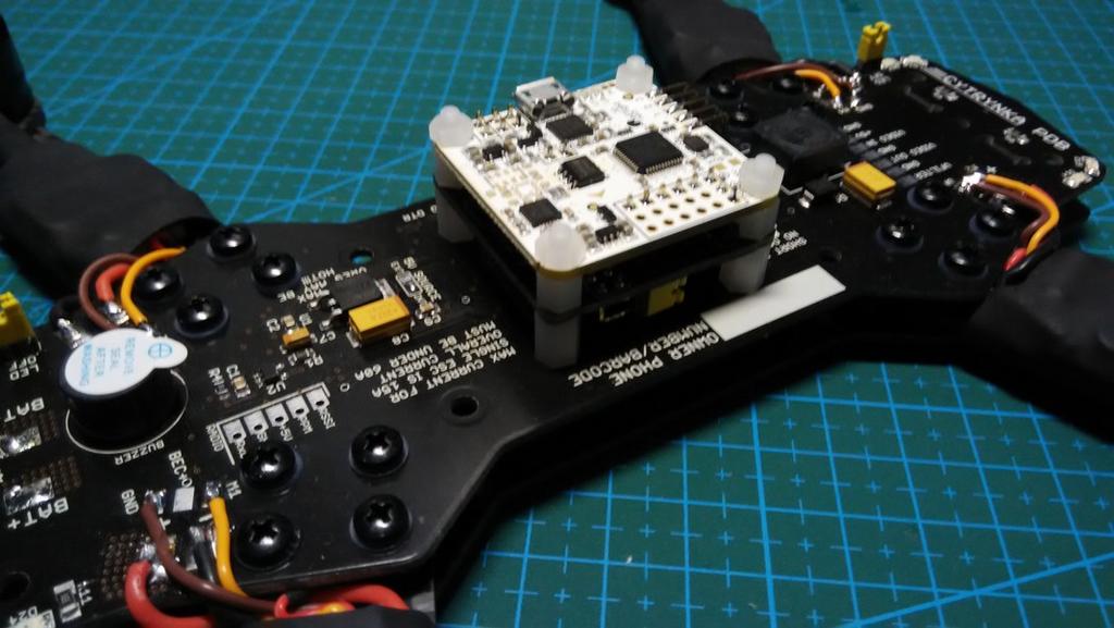
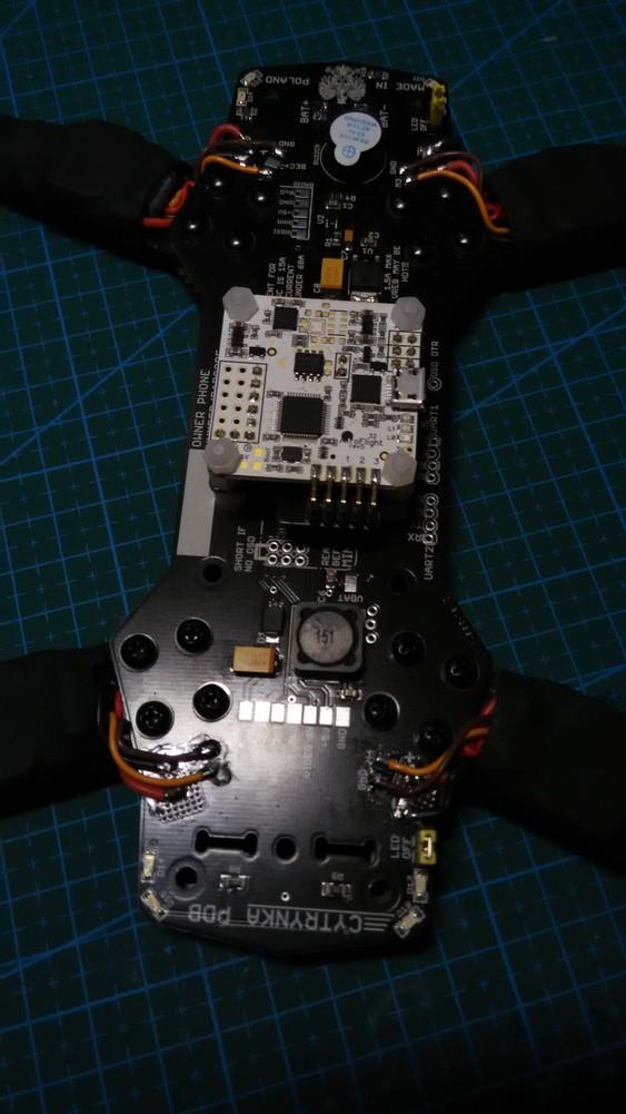
19 Some photos of our last installation 19
20 20
Rotorgeeks SSD Flight Controller Manual
 Rotorgeeks SSD Flight Controller Manual Please note this is a working document, we encourage you to visit this doc as it will continually evolve. It is intended as a guide to the SSD hardware rather than
ARRIS X-Speed 250B Assembling Manual
 ARRIS X-Speed 250B Assembling Manual Thank you for purchasing the ARRIS X-Speed 250B FPV Racing drone. Be sure to read through the entire manual before starting your build. If you bought the ARRIS X-Speed
upif7 UPIF7 Manuel d utilisation Board : upif7 Révision : 1 Date : 02/04/2018 User manual YupiF7 Révision 1 CopperYu
 UPIF7 Manuel d utilisation Board : Révision : 1 Date : 02/04/2018 1 User Manual The flight controller YupiF7 was designed with high quality components. Nonetheless, the recommandations of this user manual
Flyduino KISS Flight Controller V2 Manual v1.0
 Flyduino KISS Flight Controller V2 Manual v1.0 image: Upper / Top Side A new simplified Flight controller, the KISS FC V2 includes a complete own Flight Control Firmware development. The Idea was to get
Hyperion F3 Evo Brushed Manual
 Hyperion F3 Evo Brushed Manual The Hyperion F3 EVO Brushed Flight Controller gives you all the features in a small size and designed for micro size quads with brushed motors. Supports up to 6 motors for
FlyTower F1 Instructions V1.8 Warning Instructions for use
 FlyTower F1 Instructions V1.8 Warning Instructions for use 1, Please install ANT (must be DONE) before debugging or testing VTX(and OSD), or lead to VTX not working properly. 2, please use proper tools
KOMBINI DSHOT VERSION
 KOMBINI DSHOT VERSION Flight controller USER MANUAL Please contact us if you need further assistance: Tech support: tech@furiousfpv.com Sales support: sales@furiousfpv.com Website: http://furiousfpv.com/
20A 4 in 1 + CC3D FC. Connection diagram (To flight controller) Connection diagram 2 BATTERY GND VCC. black red. red yellow black.
 Connection diagram 2 BATTERY GND VCC. black red. red yellow black.") 4 in 1 + CC3D FC Connection diagram (To flight controller) Blue 1 Green 2 Yellow 3 White 4 Red 5 Black 6 6 5 4 Inputs 1~6 3 2 1 5V -Neg Top Botton Connection diagram 2 4 Brushless Motor 3 Brushless Motor
4 in 1 + CC3D FC Connection diagram (To flight controller) Blue 1 Green 2 Yellow 3 White 4 Red 5 Black 6 6 5 4 Inputs 1~6 3 2 1 5V -Neg Top Botton Connection diagram 2 4 Brushless Motor 3 Brushless Motor
FALCON CP-90 FPV RACING DRONE BUILD GUIDE INSTRUCTIONS V1.0
 FALCON CP-90 FPV RACING DRONE BUILD GUIDE INSTRUCTIONS V1.0 INTRODUCTION The present guide was developed to show you how to build your personal Racing Drone. The model we will be assembling together is
Betaflight F7 Quick Setup Guide
 Betaflight F7 Quick Setup Guide Welcome to your new Betaflight F7 flight controller. This guide is intended to give you the basic understanding of what your new flight controller can do, and more importantly,
Flight Controller USER MANUAL VERSION 1.0
 FORTINI F4 Flight Controller USER MANUAL VERSION 1.0 Please contact us if you need further assistance: Tech support: tech@furiousfpv.com Sales support: sales@furiousfpv.com Website: http://furiousfpv.com/
Atlatl FPV Video Transmitter
 Atlatl FPV Video Transmitter User Manual & Installation Guide V1.1 Contents Overview... 1 Features Specifications Warranty Pinout Diagram and Channel Table... 2 Installation Guide... 3 Functions... 6 Channel-Change
FORTINI F4 OSD. Flight Controller USER MANUAL VERSION 1.2
 FORTINI F4 OSD Flight Controller USER MANUAL VERSION 1.2 Please contact us if you need further assistance: Tech support: tech@furiousfpv.com Sales support: sales@furiousfpv.com Website: http://furiousfpv.com/
F-35 LIGHTNING FLIGHT CONTROLLER USER MANUAL VERSION 1.2
 F-35 LIGHTNING FLIGHT CONTROLLER USER MANUAL VERSION 1.2 Please contact us if you need further assistance: Tech support: tech@furiousfpv.com Sales support: sales@furiousfpv.com Website: http://furiousfpv.com/
3. ESC Calibration... 9
 Instruction Manual V1.3 Feature... 1 Hardware And Connection... 2 Motor Connection... 5 Aircraft assembly... 5 Parameter Adjustment Installation... 5 1.Program driver installation:... 5 2. Install Configuration
Hermit 145 V2 Micro brushless FPV quadcopter
 Hermit 145 V2 Micro brushless FPV quadcopter Hermit 145 V2 is a newly designed micro FPV quadcopter of only 158mm (Diagonal from motor center to motor center), its small size can make it fly in a relatively
FORTINI F4. Flight controller USER MANUAL. Please contact us if you need further assistance:
 FORTINI F4 Flight controller USER MANUAL Please contact us if you need further assistance: Tech support: tech@furiousfpv.com Sales support: sales@furiousfpv.com Website: http://furiousfpv.com/ Introduction
FORTINI F4. Flight Controller USER MANUAL VERSION 1.2
 FORTINI F4 Flight Controller USER MANUAL VERSION 1.2 Please contact us if you need further assistance: Tech support: tech@furiousfpv.com Sales support: sales@furiousfpv.com Website: http://furiousfpv.com/
SKYLINE32. Feature
 Instruction Manual V1.2 Key Features... 1 Hardware And Connection... 2 Connecting Motor... 4 Aircraft Assembly... 5 Configuration Software... 1. Install Driver... 5 2. Install Configuration Software...
# Kakute F7. User Manual & Installation Guide v1.0
 #11033 User Manual & Installation Guide v1.0 Contents Overview... 1 Features Specifications Warranty and Return Policy Pinout Diagram... 4 Installation Guide... 5 Updating Betaflight Firmware... 12 Installing
HGLRC F4 V6PRO (FC&VTX) Manual
 Manual") HGLRC F4 V6PRO (FC&VTX) Manual 1 Specifications CPU: STM32F405RGT6, dual open 8K MPU:MPU6000-SPI connection Built-in 5V/3A BEC output Direct welding ESC PDB Built-in current sensor Black box FLASH 16M
HGLRC F4 V6PRO (FC&VTX) Manual 1 Specifications CPU: STM32F405RGT6, dual open 8K MPU:MPU6000-SPI connection Built-in 5V/3A BEC output Direct welding ESC PDB Built-in current sensor Black box FLASH 16M
Content table. Version
 Content table 0 Introduction... - 3-1 Features... - 3-2 Software... - 4-3 Installation... - 4-4 First verifications... - 5-5 Upgrading to the latest firmware... - 8-6 Basic setup... - 11 - Version Version
Atlatl Mini FPV Video Transmitter V1.0
 Atlatl Mini FPV Video Transmitter V1.0 User Manual & Installation Guide [Type here] [Type here] Contents Overview... 1 Features Specifications Warranty Pinout Diagram and Channel Table... 3 Installation
# Kakute F4 (V2) User Manual & Installation Guide v1.1
 User Manual & Installation Guide v1.1") #11030 (V2) User Manual & Installation Guide v1.1 Contents Overview... 1 Features Specifications Warranty and Return Policy Pinout Diagram... 4 Installation Guide... 5 Updating Betaflight Firmware... 10
#11030 (V2) User Manual & Installation Guide v1.1 Contents Overview... 1 Features Specifications Warranty and Return Policy Pinout Diagram... 4 Installation Guide... 5 Updating Betaflight Firmware... 10
Flight Controller USER MANUAL VERSION 1.0
 PIKO F4 Flight Controller USER MANUAL VERSION 1.0 Please contact us if you need further assistance: Tech support: tech@furiousfpv.com Sales support: sales@furiousfpv.com Website: http://furiousfpv.com/
SmartFPV RC Camera Control v2. User Guide (RCCC v2 without option to power cameras from RC receiver)
") SmartFPV RC Camera Control v2 User Guide (RCCC v2 without option to power cameras from RC receiver) 6/9/2013 INTRODUCTION SmartFPV RC Camera Control board (RCCC) is multifunctional RC control board designed
SmartFPV RC Camera Control v2 User Guide (RCCC v2 without option to power cameras from RC receiver) 6/9/2013 INTRODUCTION SmartFPV RC Camera Control board (RCCC) is multifunctional RC control board designed
Kakute F4 AIO AIO (V2)
") #11031 AIO (V2) User Manual & Installation Guide v1.0 Contents Overview... 1 Features Specifications Warranty and Return Policy Pinout Diagram... 4 Installation Guide... 5 Updating Betaflight Firmware...
#11031 AIO (V2) User Manual & Installation Guide v1.0 Contents Overview... 1 Features Specifications Warranty and Return Policy Pinout Diagram... 4 Installation Guide... 5 Updating Betaflight Firmware...
Kakute F4 Flight Controller
 Flight Controller With Betaflight OSD User Manual & Installation Guide v1.1 Contents Overview... 1 Features Specifications Warranty and Return Policy Pinout Diagram... 3 Installation Guide... 4 Updating
X-RACER KL-EX90 INSTALLATION INSTRUCTIONS
 X-RACER KL-EX90 INSTALLATION INSTRUCTIONS FPV MODEL LIMITED Step 1:Check all the parts in case there s any missing. 1 x KL-EX90 Frame 4 x Dragonfly MC1105 7500kv Micro Class Racing Motor 1 x Flycolor RAPTOR
MINDPX. User Guide. Autopilot System V1.2
 MINDPX Autopilot System User Guide V1.2 Component List 1. MindPX 7. USB cable 2. 6-pin cable 8. M2 countersink screw 6 3. 4-pin cable 9. Light pipe 2 (removed after v2.6) 4. 4 to 6 pin convertor cable
MINDRACER SPECIFICATION
 MINDRACER SPECIFICATION Highlights - Ultra mini size, weight only ~6g - High performance F4 168MHz floating point processor, super fast throttle response - Support OneShot ESC - Support PPM/SBUS/DSM radio
THIS IS THE CURRENT FF USER GUIDE AS OF PLEASE DO NOT USE ANY PREVIOUSLY DATED VERSIONS
 THIS IS THE CURRENT FF USER GUIDE AS OF 05-04-2012 PLEASE DO NOT USE ANY PREVIOUSLY DATED VERSIONS INTRODUCTION: I compiled this guide from information posted on RCGroups.COM and from GoodLuckBuy.COM where
STEP 1: MODULE MOUNTING / WIRING:
 VER1.0 PINOUT DIAGRAM: PORT 1 - INPUT 1 (S.BUS, PWM, PPM INPUT) PORT 2 - INPUT 2 (PWM MODE INPUT OR AUX OUTPUT DEFINED IN SOFTWARE) PORT 3 - OUTPUT 1 (S.BUS OUTPUT) PORT 4 - OUTPUT 2 (SERVO OUTPUT) PORT
OSDoge. Setup handbook
 OSDoge Setup handbook Revision 1, January 8 2015 1 Table of Contents 1. Hardware Overview... 3 2. Hardware capabilities overview... 4 3. Connections overview... 5 4. Configuring power supplies... 6 1.1.
THIS IS THE CURRENT FF USER GUIDE AS OF PLEASE DO NOT USE ANY PREVIOUSLY DATED VERSIONS
 THIS IS THE CURRENT FF USER GUIDE AS OF 02-26-2012 PLEASE DO NOT USE ANY PREVIOUSLY DATED VERSIONS INTRODUCTION: I compiled this guide from information posted on RCGroups.COM and from GoodLuckBuy.COM where
PIKO F4 OSD. Flight Controller USER MANUAL VERSION 1.0
 PIKO F4 OSD Flight Controller USER MANUAL VERSION 1.0 Please contact us if you need further assistance: Tech support: tech@furiousfpv.com Sales support: sales@furiousfpv.com Website: http://furiousfpv.com/
VTX OSD Board USER MANUAL VERSION 1.0
 INNOVA V4 VTX OSD Board USER MANUAL VERSION 1.0 Please contact us if you need further assistance: Tech support: tech@furiousfpv.com Sales support: sales@furiousfpv.com Website: http://furiousfpv.com/ 1
FORTINI F4 OSD REV.3
 FORTINI F4 OSD REV.3 Flight Controller USER MANUAL VERSION 1.0 Please contact us if you need further assistance: Tech support: tech@furiousfpv.com Sales support: sales@furiousfpv.com Website: http://furiousfpv.com/
User Manual for ARRIS FPV250 with SPRacing F3 Flight Controller With Cleanflight
 User Manual for ARRIS FPV250 with SPRacing F3 Flight Controller With Cleanflight 1.12.00 1. How to Connect the F3 Flight Controller to the Computer. 1.1. Do not connect the F3 flight controller to the
Manual. There is also a growing array of upgrades and customizations, both functional and cosmetic available from quadquestions.
 Manual Thank you for purchasing the QQ190 Falcon racing quadcopter and welcome to the QQ190 team. This manual details how to physically assemble the frame. There is a diverse array of electrical components
EZ-Bv4 Datasheet v0.7
 EZ-Bv4 Datasheet v0.7 Table of Contents Introduction... 2 Electrical Characteristics... 3 Regulated and Unregulated Power Pins... 4 Low Battery Warning... 4 Hardware Features Main CPU... 5 Fuse Protection...
Content Key Features... 3 Specifications... 3 Set up...6 Binding Procedure... 6 Status LED...7 Flight Controller Set Up...7 Flight Modes Settings...9
 Makerfire BNF Micro FPV Racing Quad With F303 Betaflight Flight Controller Version 0.1 Website: www.crazepony.com Email: info@crazepony.com Content Key Features... 3 Specifications... 3 Set up...6 Binding
Seriously Pro. SP Racing F3 OSD/PDB On-Screen Display & Power Distribution Board
 Seriously Pro SP Racing F3 OSD/PDB On-Screen Display & Power Distribution Board Thank you for directly supporting the Cleanflight project with your purchase. Seriously Pro Racing F3 OSD/PDB Manual (Version
Assembly Manual. X Bolt FPV Racer Kit AZSZ2903
 Assembly Manual X Bolt FPV Racer Kit AZSZ2903 Product specifications are subject to change without notice. Due to ongoing development, the actual product may vary from images shown. This product contains
What s in the box. Connection Please see also a video tutorial at https://youtu.be/eeeutrlq8bw. Securing wire. 4 pin adapter.
 FPV1 Zaggometry Naza2FrSky Taranis Telemetrie-Adapter Page 1 of 12 What s in the box 4 pin adapter Securing wire 3 pin adapter S.Port connector Connection Please see also a video tutorial at https://youtu.be/eeeutrlq8bw
MINDRACER USER MANUAL
 MindPX T h e U l t i m a t e Racer MINDRACER USER MANUAL Highlights - Ultra mini size, weight only ~6g - High performance F4 168MHz floating point processor, super fast throttle response - Support OneShot
Pilot s Manual V1.3.1
 JBardwell F4 AIO Betaflight Flight ControlleR Pilot s Manual V1.3.1 RaceDayQuads / JBardwell F4 AIO I m Joshua Bardwell and this is the flight controller I always wished somebody would make. It s got all
A B C D REV 1 SHEET 1 OF 1 1 G NO assy_011 DW TITLE SIZE C SCALE 9/17/2016 N 2 2 FG APPROVED CHECKED QA M Henri DRAW PHALANX A B C D
 4 A BPHALANX Greetings and good fortune be on you as you have aquired your new greatness. As you work through the assembly passages, please, READ THE DIRECTIONS! There are fine points covered that you
Mini FPV Tricopter / Vtail / Quadcopter
 Mini FPV Tricopter / Vtail / Quadcopter Frame Assembly Manual / Tips and Tricks Armattan Minis Website: http://www.armattanminis.ca/ Main Armattan Website (doesn t have minis): http://www.armattanquads.com/
iosd (On Screen Display)
") iosd (On Screen Display) User Manual V2.2 For iosd Firmware Version V3.3 & iosd Assistant V4.1* July, 216 * iosd Firmware V3.3 compatible with iosd Assistant V4.1. www.dji.com 216 DJI All Rights Reserved.
iosd (On Screen Display) User Manual V2.2 For iosd Firmware Version V3.3 & iosd Assistant V4.1* July, 216 * iosd Firmware V3.3 compatible with iosd Assistant V4.1. www.dji.com 216 DJI All Rights Reserved.
Shack Clock kit. U3S Rev 2 PCB 1. Introduction
 Shack Clock kit U3S Rev 2 PCB 1. Introduction Thank you for purchasing the QRP Labs Shack Clock kit. This clock uses the Ultimate3S QRSS/WSPR kit hardware, but a different firmware version. It can be used
BEST Control System. Dave Wilkerson. September 12, 2015
 BEST Control System BEST Robotics, Inc. Dave Wilkerson September 12, 2015 Copyright 2012 BEST Robotics, Inc. All rights reserved. 1 Servos Joystick Return Kit AAA Battery Charger Analog WiFi key USB/Tether
PIGGY V2 User Manual Please contact us if you need further assistance:
 PIGGY V2 User Manual Please contact us if you need further assistance: Tech support: tech@furiousfpv.com Sales support: sales@furiousfpv.com Website: http://furiousfpv.com/ I. Specifications: - Item name:
FlyTower F3 Instructions V1.0.1 Warning Instructions for use
 FlyTower F3 Instructions V1.0.1 Warning Instructions for use 1, Please install ANT (must be DONE) before debugging or testing VTX(and OSD), or lead to VTX not working properly. 2, Please use proper tools
Arduino Uno. Arduino Uno R3 Front. Arduino Uno R2 Front
 Arduino Uno Arduino Uno R3 Front Arduino Uno R2 Front Arduino Uno SMD Arduino Uno R3 Back Arduino Uno Front Arduino Uno Back Overview The Arduino Uno is a microcontroller board based on the ATmega328 (datasheet).
Disposing of old devices
 Manual Disposing of old devices The symbol below indicates that that product must be disposed of separately, not with your regular waste. Please take this product to an official collection point. By separating
ARDUINO MEGA 2560 REV3 Code: A000067
 ARDUINO MEGA 2560 REV3 Code: A000067 The MEGA 2560 is designed for more complex projects. With 54 digital I/O pins, 16 analog inputs and a larger space for your sketch it is the recommended board for 3D
Adafruit Metro Mini. Created by lady ada. Last updated on :12:28 PM UTC
 Adafruit Metro Mini Created by lady ada Last updated on 2018-01-24 08:12:28 PM UTC Guide Contents Guide Contents Overview Pinouts USB & Serial converter Microcontroller & Crystal LEDs Power Pins & Regulators
Ultimate LPF kit: Relay-switched LPF kit
 Ultimate LPF kit: Relay-switched LPF kit PCB Revision 4 1. Introduction Thank you for purchasing the QRP Labs relay-switched low-pass filter (LPF) kit. This kit is designed to complement the Ultimate3
QRPometer Assembly Manual Copyright 2012 David Cripe NM0S The 4 State QRP Group. Introduction
 QRPometer Assembly Manual Copyright 2012 David Cripe NM0S The 4 State QRP Group Introduction Thank you for purchasing a QRPometer. We hope you will enjoy building it and and find it a useful addition to
3 pyro output datalogger altimeter with an ATmega 328 microcontroller Kit assembly instructions
 3 pyro output datalogger altimeter with an ATmega 328 microcontroller Kit assembly instructions Version date Author Comments 1.0 29/05/2013 Boris du Reau Initial version Rocket Type Micro-max Model Mid
Overview. Connect the Flight Control Board and Receiver
 Overview This article only describes the methods for connecting the receiver and ESC to the flight control board. You may need to refer to other materials for installation of other devices. If conditions
Innovation First, Inc Full-Size Robot Controller Reference Guide
 2004 Full-Size Robot Controller Reference Guide 2.19.2004 www.innovationfirst.com Page 2 Table of Contents 1. Robot Controller Overview... 3 2. Main Power Input... 4 3. Battery Backup Power... 4 4. PROGRAM...
SEXPANDER A small Spektrum DX8 Channel Expander
 SEXPANDER A small Spektrum DX8 Channel Expander A normal DX8 (with the little Satellite Receiver) can only send on 8 Channels (4 Channels for Throttle, Yaw, Nick & Roll), 3 Switch-Channels and a poti.
This is an inspection failure, not meeting the requirement of >10k Ohm between either PD battery post and chassis.
 Troubleshooting This is a document put together by CSA Laura Rhodes that contains a lot of information about troubleshooting steps for a lot of common control system problems encountered at events. No
Colecovision 5v Memory Mod Installation
 Colecovision 5v Memory Mod Installation The Colecovision suffers from common failure points: the power supply, power switch, and 4116 DRAM. The power supply suffers from poor soldering, the power switch
Pridgen Vermeer Robotics ATmega128 Revision 0
 Features: 6x 8-bit I/O Ports 4x A/D Inputs 6x PWM Headers 2x RS 232 Terminals Power Bus LCD Header (4-bit mode) Smart Power Connecter Power Switch Header Power LED Debug LED Note: Some pins have multiple
FPV racer Frame class:
 By FPV racer Frame class: Prop. size: Motor size: Power: Flight Cam: Material: 250 Up to 6" M3 or M2 attached motors of choice Up to 4S 1500 mah housed inside frame as optimum, depending on brand Tie-strap
ARRIS Zhao Yun Pro User Manual. Content
 ARRIS Zhao Yun Pro User Manual Thank you for buying ARRIS Zhao Yun Pro 3-Axis brushless Gimbal. Each gimbal has been adjusted and tested before we send it out. For this gimbal, Most customers can plug
ESPino - Specifications
 ESPino - Specifications Summary Microcontroller ESP8266 (32-bit RISC) WiFi 802.11 (station, access point, P2P) Operating Voltage 3.3V Input Voltage 4.4-15V Digital I/O Pins 9 Analog Input Pins 1 (10-bit
Make a Quadcopter using KK Flight Controller
 Make a Quadcopter using KK 2.1.5 Flight Controller 1 Typical Applications A quadcopter, also called a quadrotor helicopter or quadrotor, is a multirotor helicopter that is lifted and propelled by four
3-axis Gyro & Flight Stabilizer for fixed-wing
 A3 Super II 3-axis Gyro & Flight Stabilizer for fixed-wing User Manual 2015.4.20 Revision For Firmware Version V1.1, V1.0, Data Version V1.0 Copyright 2011-2015 HOBBYEAGLE. All Rights Reserved. http://www.hobbyeagle.com
Wii Nunchuk Transceiver. Wiring Diagrams
 Wii Nunchuk Transceiver Wiring Diagrams Wii Nunchuk Controller Wiring SCL SCL SDA +3v3 +3v3 Det SDA To Nunchuk Controller Top View Bottom View Bottom View 2.4GHz Wireless Transceiver CMD RXD TXD VCC 220Ω
ARDUINO UNO REV3 SMD Code: A The board everybody gets started with, based on the ATmega328 (SMD).
.") ARDUINO UNO REV3 SMD Code: A000073 The board everybody gets started with, based on the ATmega328 (SMD). The Arduino Uno SMD R3 is a microcontroller board based on the ATmega328. It has 14 digital input/output
ARDUINO UNO REV3 SMD Code: A000073 The board everybody gets started with, based on the ATmega328 (SMD). The Arduino Uno SMD R3 is a microcontroller board based on the ATmega328. It has 14 digital input/output
ARDUINO MEGA ADK REV3 Code: A000069
 ARDUINO MEGA ADK REV3 Code: A000069 OVERVIEW The Arduino MEGA ADK is a microcontroller board based on the ATmega2560. It has a USB host interface to connect with Android based phones, based on the MAX3421e
Single cable kit for the FCB1010
 Single cable kit for the FCB1010 1. What is it? With this kit, you can turn your FCB1010 into a phantom powered floorboard, which can do 2-way MIDI communication over one single cable. After installing
AeroCore 2 for DragonBoard
 AeroCore 2 for DragonBoard TM Gumstix, Inc. shall have no liability of any kind, express or implied, arising out of the use of the Information in this document, including direct, indirect, special or consequential
PVK40. User's manual. Feature Rich Development and Educational Kit for 40-pin Microchip PIC microcontrollers
 PVK40 User's manual Feature Rich Development and Educational Kit for 40-pin Microchip PIC microcontrollers CONTENTS PVK40 3 On-board peripherals: 3 Power supply 4 Microcontroller 4 Reset circuitry 4 Oscilator
QUICK START GUIDE (DIY)
") TYRO99 QUICK START GUIDE (DIY) Package included: 1 x 210mm frame kit 2 x 2206 2150KV brushless motor CW 2 x 2206 2150KV brushless motor CCW 1 x 4 IN 1 30A BLHeli_S ESC 1 x Customized F4 flight controller
TYRO99 QUICK START GUIDE (DIY) Package included: 1 x 210mm frame kit 2 x 2206 2150KV brushless motor CW 2 x 2206 2150KV brushless motor CCW 1 x 4 IN 1 30A BLHeli_S ESC 1 x Customized F4 flight controller
TLE9869 Eval.Kit V1.0 Users Manual
 TLE9869 Eval.Kit V1.0 Users Manual Contents Abbreviations... 2 1 Concept... 3 2 Interconnects... 4 3 Test Points... 5 4 Jumper Settings... 6 5 Communication Interfaces... 7 5.1 LIN (via Banana jack and
SCREAMER 250 RACE PENTACOPTER
 SCREAMER 250 RACE PENTACOPTER USER MANUAL SPECIFICATIONS -Wheel base: 250mm -Frame weight: 260g -Flying weight: 610g (4S 1500mah lipo included) -Flight time: 3-5 mins(flight time reduces by using rear
CRIUS ALL IN ONE PRO v1.0 Multi Rotor Flight Controller. Manual rev 1.3. By Quadframes
 CRIUS ALL IN ONE PRO v1.0 Multi Rotor Flight Controller Manual rev 1.3 By Quadframes Features: Supported MegaPirateNG and MultiWii firmware Up to 8-axis motor output 8 input channels for standard receiver
TG VR Gimbal User Manual V Accsoon. All Rights Reserved.
 TG20 360 VR Gimbal User Manual V1.0 20161209 www.accsoon.com E-mail: salse@accsoon.com 0 Disclaimers and Warnings Congratulations on purchasing you new VR Gimbal. Please read this manual and disclaimer
OpenSprinkler v2.1u Build Instructions
 OpenSprinkler v2.1u Build Instructions (Note: all images below are 'clickable', in order for you to see the full-resolution details. ) Part 0: Parts Check Part 1: Soldering Part 2: Testing Part 3: Enclosure
PICAXE CONNECT (AXE210)
") PICAXE CONNECT (AXE10) Description: The AXE10 Connect board has been designed as a experimental project board for users wishing to learn how to interface a PICAXE chip to the Maxstream module or a LocSense
PICAXE CONNECT (AXE10) Description: The AXE10 Connect board has been designed as a experimental project board for users wishing to learn how to interface a PICAXE chip to the Maxstream module or a LocSense
OpenSprinkler v2.2u Build Instructions
 OpenSprinkler v2.2u Build Instructions (Note: all images below are 'clickable', in order for you to see the full-resolution details. ) Part 0: Parts Check Part 1: Soldering Part 2: Testing Part 3: Enclosure
Hardware Manual CNC760
 Hardware Manual CNC760 Revision 3 6 December, 2017 Released Copyright 2017 by Eding CNC History: Revision Date Author 1 22-5-2017 AB 2 23-6-2017 AB 3 6-12-2017 AB Revision overview: Revision Remarks 1
XBee Grove Development Board. User Guide
 XBee Grove Development Board User Guide Revision history 90001457-13 Revision Date Description A June 2016 Converted files to new format and completed minor updates to screens and content. B October 2017
HARDWARE MANUAL TMCM-1613 TMCM-1613-REC. Hardware Version V TRINAMIC Motion Control GmbH & Co. KG Hamburg, Germany.
 MODULES FOR BLDC MOTORS MODULES Hardware Version V 1.10 HARDWARE MANUAL + + TMCM-1613 + + Single Axis BLDC Controller / Driver Block-commutation Hall-sensor based Analog+digital inputs / outputs Up-to
AeroCore 2 for Intel Joule Module
 AeroCore 2 for Intel Joule Module TM Gumstix, Inc. shall have no liability of any kind, express or implied, arising out of the use of the Information in this document, including direct, indirect, special
SP-7 AHRS. Firmware upgrade instructions. Installation and calibration
 SP-7 AHRS Firmware upgrade instructions Installation and calibration General This document describes the firmware upgrade procedure and new functionality of the SP-7 Firmware release. The firmware upgrade
Arduino shield kit. 1) Low Pass Filter (LPF) kit (available for LF/MF/HF/VHF bands 2,200m to 6m)
 Low Pass Filter (LPF) kit (available for LF/MF/HF/VHF bands 2,200m to 6m)") Arduino shield kit 1. Introduction The QRP Labs Arduino shield kit is a versatile shield that can be used for various purposes. Write your own Arduino sketch to define the functionality! For example: 1)
Arduino shield kit 1. Introduction The QRP Labs Arduino shield kit is a versatile shield that can be used for various purposes. Write your own Arduino sketch to define the functionality! For example: 1)
Rover 5. Explorer kit
 Rover 5 Explorer kit The explorer kit provides the perfect interface between your Rover 5 chassis and your micro-controller with all the hardware you need so you can start programming right away. PCB Features:
LibrePilot GCS Tutorial
 LibrePilot GCS Tutorial BY Wirginia Tomczyk page 1 of 13 Introduction The first dron of Drone Team project use Open Pilot Copter Control (CC). It is the flight controller supported by LibrePilot firmware.
Goal: We want to build an autonomous vehicle (robot)
") Goal: We want to build an autonomous vehicle (robot) This means it will have to think for itself, its going to need a brain Our robot s brain will be a tiny computer called a microcontroller Specifically
Goal: We want to build an autonomous vehicle (robot) This means it will have to think for itself, its going to need a brain Our robot s brain will be a tiny computer called a microcontroller Specifically
CYCLOPS TORNADO OSD V1.0 manual
 CYCLOPS TORNADO OSD V1.0 manual Thanks for buying and using CYCLOPS OSD series products, please read this manual carefully before use. Installation of connections Important: select Jumper instructions:
ARDUINO UNO REV3 Code: A000066
 ARDUINO UNO REV3 Code: A000066 The UNO is the best board to get started with electronics and coding. If this is your first experience tinkering with the platform, the UNO is the most robust board you can
Manual DJI Phantom 2 Vision Dronexpert Gimbal
 Manual DJI Phantom 2 Vision Dronexpert Gimbal V2 1. Remove battery from the phantom. 2. Place the Phantom upside down. 3. Pull the jackplug out of the camera 4. Lift the frame carefully from rubber holders.
Prototyping Module Datasheet
 Prototyping Module Datasheet Part Numbers: MPROTO100 rev 002 Zenseio LLC Updated: September 2016 Table of Contents Table of Contents Functional description PROTOTYPING MODULE OVERVIEW FEATURES BLOCK DIAGRAM
Vout R LED2 LED1 Nr. of LEDs R Ohm Current ma Vout V Ardunio Pin9
 Tutorial AR Drone Miru Mod on Windows 7 with DX6i, Part 5 V. UFO Doctor, Aug th, 0 7. VLBA experiments with external LED at Arduino Pin9 Introduction Miru Mod 008 offered us the Visible Low Battery Alert