How can I. Implement a Hot Standby QEIO Architecture? Develop your project
|
|
|
- Brooke Daniel
- 6 years ago
- Views:
Transcription
1 How can I Implement a Hot Standby QEIO Architecture? Tested Validated Documented Architecture High availability automation system Develop your project
2
3 Important Information People responsible for the application, implementation and use of this document must make sure that all necessary design considerations have been taken into account and that all laws, safety and performance requirements, regulations, codes, and applicable standards have been obeyed to their full extent. Schneider Electric provides the resources specified in this document. These resources can be used to minimize engineering efforts, but the use, integration, configuration, and validation of the system is the user s sole responsibility. Said user must ensure the safety of the system as a whole, including the resources provided by Schneider Electric through procedures that the user deems appropriate. Notice This document is not comprehensive for any systems using the given architecture and does not absolve users of their duty to uphold the safety requirements for the equipment used in their systems, or compliance with both national or international safety laws and regulations. Readers are considered to already know how to use the products described in this document. This document does not replace any specific product documentation. The following special messages may appear throughout this documentation or on the equipment to warn of potential hazards or to call attention to information that clarifies or simplifies a procedure. 3
4 The addition of this symbol to a Danger or Warning safety label indicates that an electrical hazard exists, which will result in personal injury if the instructions are not followed. This is the safety alert symbol. It is used to alert you to potential personal injury hazards. Obey all safety messages that follow this symbol to avoid possible injury or death. DANGER DANGER indicates an imminently hazardous situation which, if not avoided, will result in death or serious injury. WARNING WARNING indicates a potentially hazardous situation which, if not avoided, can result in death or serious injury. CAUTION CAUTIÓN indicates a potentially hazardous situation which, if not avoided, can result in minor or moderate injury. CAUTION CAUTION, used without the safety alert symbol, indicates a potentially hazardous situation which, if not avoided, can result in equipment damage. PLEASE NOTE Electrical equipment should be installed, operated, serviced, and maintained only by qualified personnel. No responsibility is assumed by Schneider Electric for any consequences arising out of the use of this material. A qualified person is one who has skills and knowledge related to the construction, operation and installation of electrical equipment, and has received safety training to recognize and avoid the hazards involved. 4
5 Before You Begin This automation equipment and related software is used to control a variety of industrial processes. The type or model of automation equipment suitable for each application will vary depending on factors such as the control function required, degree of protection required, production methods, unusual conditions and government regulations etc. In some applications more than one processor may be required when backup redundancy is needed. Only the user can be aware of all the conditions and factors present during setup, operation and maintenance of the solution. Therefore only the user can determine the automation equipment and the related safeties and interlocks which can be properly used. When selecting automation and control equipment and related software for a particular application, the user should refer to the applicable local and national standards and regulations. The National Safety Council s Accident Prevention Manual also provides much useful information. Ensure that appropriate safeties and mechanical/electrical interlocks protection have been installed and are operational before placing the equipment into service. All mechanical/electrical interlocks and safeties protection must be coordinated with the related automation equipment and software programming. NOTE: Coordination of safeties and mechanical/electrical interlocks protection is outside the scope of this document. START UP AND TEST Following installation but before using electrical control and automation equipment for regular operation, the system should be given a start up test by qualified personnel to verify the correct operation of the equipment. It is important that arrangements for such a check be made and that enough time is allowed to perform complete and satisfactory testing. EQUIPMENT OPERATION HAZARD Follow all start up tests as recommended in the equipment documentation. Store all equipment documentation for future reference. Software testing must be done in both simulated and real environments. Verify that the completed system is free from all short circuits and grounds, except those grounds installed according to local regulations (according to the National Electrical Code in the USA, for example). If high-potential voltage testing is necessary, follow recommendations in the equipment documentation to prevent accidental equipment damage. Before energizing equipment: Remove tools, meters, and debris from equipment Close the equipment enclosure door Remove ground from incoming power lines Perform all start-up tests recommended by the manufacturer OPERATION AND ADJUSTMENTS The following precautions are from NEMA Standards Publication ICS (English version prevails): Regardless of the care exercised in the design and manufacture of equipment or in the selection and rating of components; there are hazards that can be encountered if such equipment is improperly operated. It is sometimes possible to misadjust the equipment and thus produce unsatisfactory or unsafe operation. Always use the manufacturer s instructions as a guide for functional adjustments. Personnel who have access to these adjustments should be familiar with the equipment manufacturer s instructions and the machinery used with the electrical equipment. Only those operational adjustments actually required by the operator should be accessible to the operator. Access to other controls should be restricted to prevent unauthorized changes in operating characteristics. 5

6 WARNING UNEXPECTED EQUIPMENT OPERATION Only use software tools approved by Schneider Electric for use with this equipment. Update your application program every time you change the physical hardware configuration. Failure to follow these instructions can cause death, serious injury or equipment damage. INTENTION This document is intended to provide a quick introduction to the described system. It is not intended to replace any specific product documentation, nor any of your own design documentation. On the contrary, it offers information additional to the product documentation on installation, configuration and implementing the system. The architecture described in this document is not a specific product in the normal commercial sense. It describes an example of how Schneider Electric and third-party components may be integrated to fulfill an industrial application. A detailed functional description or the specifications for a specific user application is not part of this document. Nevertheless, the document outlines some typical applications where the system might be implemented. The architecture described in this document has been fully tested in our laboratories using all the specific references you will find in the component list near the end of this document. Of course, your specific application requirements may be different and will require additional and/or different components. In this case, you will have to adapt the information provided in this document to your particular needs. To do so, you will need to consult the specific product documentation of the components that you are substituting in this architecture. Pay particular attention in conforming to any safety information, different electrical requirements and normative standards that would apply to your adaptation. It should be noted that there are some major components in the architecture described in this document that cannot be substituted without completely invalidating the architecture, descriptions, instructions, wiring diagrams and compatibility between the various software and hardware components specified herein. You must be aware of the consequences of component substitution in the architecture described in this document as substitutions may impair the compatibility and interoperability of software and hardware. 6
7 This document is intended to describe how implement a Hot Standby system using a Quantum Ethernet Remote I/O solution. DANGER HAZARD OF ELECTRIC SHOCK, BURN OR EXPLOSION Only qualified personnel familiar with low and medium voltage equipment are to perform work described in this set of instructions. Workers must understand the hazards involved in working with or near low and medium voltage circuits. Perform such work only after reading and understanding all of the instructions contained in this bulletin. Turn off all power before working on or inside equipment. Use a properly rated voltage sensing device to confirm that the power is off. Before performing visual inspections, tests, or maintenance on the equipment, disconnect all sources of electric power. Assume that all circuits are live until they have been completely de-energized, tested, grounded, and tagged. Pay particular attention to the design of the power system. Consider all sources of power, including the possibility of back feeding. Handle this equipment carefully and install, operate, and maintain it correctly in order for it to function properly. Neglecting fundamental installation and maintenance requirements may lead to personal injury, as well as damage to electrical equipment or other property. Beware of potential hazards, wear personal protective equipment and take adequate safety precautions. Do not make any modifications to the equipment or operate the system with the interlocks removed. Contact your local field sales representative for additional instruction if the equipment does not function as described in this manual. Carefully inspect your work area and remove any tools and objects left inside the equipment. Replace all devices, doors and covers before turning on power to this equipment. All instructions in this manual are written with the assumption that the customer has taken these measures before performing maintenance or testing. Failure to follow these instructions will result in death or serious injury. 7
8 The TVDA Collection Tested Validated Documented Architecture (TVDA) guides are meant to help in the implementation of specified solutions. TVDA guides provide a tested and validated example of the proposed architecture to help project engineers and Alliance System Integrators during the design and implementation of a project. The TVDA helps users analyze their architectures, confirm the feasibility of their systems and speed up system implementation. Each TVDA provides users with: A reference architecture based on Schneider Electric s PlantStruxure solution Documentation of the system requirements of the architecture response times, number of devices, features Design choices for the application software and hardware architectures Test results to confirm the requirements are met All explanations and applications have been developed by both Schneider Electric experts and system integrators in our PlantStruxure labs. TVDAs are not intended to be used as substitutes for the technical documentation related to the individual components, but rather to complement those materials. Development Environment Each TVDA has been developed in one of our solution platform labs using a typical PlantStruxure architecture. PlantStruxure, the process automation system from Schneider Electric, is a collaborative architecture that allows industrial and infrastructure companies to meet their automation needs while at the same time addressing their growing energy efficiency requirements. In a single environment, measured energy and process data can be analyzed to yield a holistically optimized plant. 8
9 Table of Contents 1. Introduction Purpose Customer Challenges Prerequisites Project Methodology Glossary Selection PAC Station Network Hardware summary Software Design SCADA System Quantum Hot Standby System Configuration SCADA configuration Switches configuration PAC configuration Implementation Monitoring Elements in the Primary Section Monitoring Elements in the Standby Section Switchover Management SCADA
10 6. Validation Functional tests Performance tests Conclusion Appendix SCADA configuration Performance tests chronograms
11 1-Introduction 1. Introduction 1.1. Purpose The purpose of this document is to provide recommendations, guidelines and examples on how to implement a high availability automation system using a PlantStruxure system, which is based on a Quantum Ethernet I/O solution and a Vijeo Citect SCADA system. This guide focuses on the different ways to increase availability through redundancy at various levels of an automation system, and proposes a methodology to implement an efficient high availability automation system. Each step in the implementation of this system from selection to operation is broadly described and illustrated with examples. The solutions described in this TVDA are fully part of the PlantStruxure control system. Note: A System Technical Note entitled How can I increase the availability of a system? detailing the theoretical basics of high availability has already been issued Customer Challenges 1.3. Prerequisites The challenges for customers in industries where availability and reliability are major concerns include: Providing a high level of availability and reliability Having a short recovery following system Fast switchover times Multiple levels of redundancy ensuring maintainability Providing a system with remote I/O management for large scale plants (as needed by tunneling or mining industries, for example) This TVDA suggests approaches to meet these challenges and highlights specific areas which can benefit from using a PlantStruxure Control System. We recommend readers have a good knowledge of the following software: Unity Pro Vijeo Citect 11

12 1-Introduction We also recommend readers become familiar with the STN How can I increase the availability of a system? and have some knowledge of Schneider Electric s Quantum PACs. Following is a short summary of the general principles of redundancy and its application in an automation system. The following PlantStruxure architecture illustrates an example of the different layers where redundancy can be implemented. Control room Data servers Control network PAC stations Field network Field devices The diagram also represents a wide range of hardware setups, which demonstrates the ability to achieve various levels of redundancy. Note: The figure above does not correspond to the architecture of this document. It simply helps to give understanding of the different components of a full architecture. The availability of an automation system can be increased at different layers: SCADA system: The SCADA system has to handle data acquisition, graphics, events, alarms, trends and reports. SCADA server redundancy enhances the likelihood these services will continue to operate without loss of data in the case of a system interruption. Different software and hardware configurations allow different levels of availability. 12
13 1-Introduction Control network: Well defined topology and management of the control network increase network availability and reliability. This, in turn, makes communication between the SCADA system and the PAC stations more reliable. Several network topologies and network protocols are available to achieve the optimal level of availability and to fit the needs of the entire system. PAC station: Depending on your requirements in terms of I/O number and topology, you can choose between a Quantum or a Premium Hot Standby PAC system. The type of field network and I/O system (local or distributed) are also elements to consider before selecting a PAC station. Field network: Redundancy can also be applied to the field network. As was the case for the control network, a well defined topology and management of the network increase field network availability Project Methodology This TVDA describes the project methodology and includes the following phases: Selection, Design, Configuration, Implementation and Performance. This guide is focused on the Quantum architecture with Ethernet I/O. Its features are described in the Selection phase. Beginning with process analysis and user requirements, we identify and develop common functionalities for the selected architecture. These key functions are explained in the Design, Configuration and Implementation phases. Finally, the Performance phase summarizes the results of different tests performed on the architecture. The phases described in this document are: Selection: in this phase the selection procedure to define a redundant architecture is presented. Design: this phase covers the operational principles of the different components of high availability architecture: SCADA system Network PAC station 13
14 1-Introduction Configuration: in this phase the configuration information for the different components of the architecture is detailed. Implementation: using the same architecture and components, information is provided about the final customization which was completed to address the project requirements. Validation: a summary of the architecture performance in response to simulated events is presented in this phase Glossary Term ART Control network CRP DIO DRS ERIO Field network Description Application Response Time the delay between an event, such as an input changing state or a commanded output, and the system response to that event The portion of the control system network where process data is primarily transferred. It includes SCADA-to-PAC traffic and functional-unit-pac-to-functional-unit-pac traffic Quantum Ethernet RIO adapter module located in each RIO drop Quantum 140 CRP remote I/O scanner located in the local rack Distributed I/O Ethernet-enabled devices which can include Schneider Electric and/or third-party products Dual-Ring Switch a Schneider Electric ConneXium Ethernet switch with the necessary configuration to support the ERIO main ring, as well as a DIO or ERIO sub ring, and DIO clouds. Other switching devices are not permitted in the ERIO network Ethernet Remote Input/Output architecture where the I/Os are deported on distant racks; the racks are connected to the PAC using an Ethernet connection The portion of the control system network in which field device monitoring and control traffic is primarily transferred. It includes PAC-to-I/O, PAC-to-drive traffic, and primary-pac-tohot-standby-pac traffic 14
15 1-Introduction Term IU_ERIO NOE PAC Scan time Quantum EIO RIO RPI Description Immediate update I/O a function block in Unity Pro which allows you to schedule the reading of selected inputs or the writing of selected outputs before the current logic scan is complete. This function block must not be used in a hot standby system. Quantum140 NOE 771 xx Ethernet communication module Programmable Automation Controller The time required to process the PAC user application logic and execute all communication tasks associated with the scan The Quantum Ethernet remote I/O solution Remote I/O I/O devices used when predictable deterministic performance is expected Requested Packet Interval the amount of time between packets of input data transmitted by a, expressed in milliseconds 15
16 1-Introduction 16

17 2-Selection 2. Selection 2.1. PAC Station Depending on the level of availability required, redundancy is applied in various ways. This section describes the various options available in terms of redundancy and availability. This TVDA is a guide for implementing high availability using Hot Standby Quantum Ethernet I/O and Ethernet Remote I/O drops. We chose to use the CPU reference 140 CPU as it can address applications with a distance of up to 10 kilometers between the two Hot Standby CPUs. This is done via an optical single mode Ethernet port. In addition, this CPU supports more memory, greater size and a higher speed exchange capacity between the two Hot Standby CPUs Network Network topologies Various topologies and protocols are used to increase the availability of the network (both control and field networks). The main idea is to create alternative paths to access devices so when a network element on one path stops functioning another path is used. Ring topologies are mainly used to increase the level of network availability. Network redundancy management protocols, such as RSTP or MRP, are used for network recovery in case part of the network ceases to function. Our project features two sub-networks: A control network linking PACs and SCADA A field network linking PACs, remote Ethernet I/O and other devices Referring to the standard PlantStruxure architectures, we will work with Redundant Flexible Distributed (RFD) and Redundant Compact Evolutive (RCE) architectures. Redundant Compact Evolutive architecture This architecture includes Ethernet remote I/Os. 17
18 2-Selection Redundant Compact Evolutive architecture RING 1 : RING 2 : SW1 PRIMARY SERVER VIJEO CITECT CLIENT SW2 STANDBY SERVER RING 1 : RING 2 : FIELD NETWORK { Control RING 1 Control RING 2 FIELD MAIN RING EIO SUB-RING 1 EIO SUB-RING 2 QUANTUM REDUNDANCY LINK SW4 SW SW SW6 COPPER CABLE OPTICAL FIBER NOE 1 : NOE 2 : NOE 3 : NOE1 NOE2 NOE3 CRP NOE1 NOE2 NOE3 CRP Distant devices NOE 1 : NOE 2 : CRP : NOE 3 : CRP : PRIMARY QUANTUM SW C15 SW8 C15 STANDBY QUANTUM SW11 SW C C5 DROP 1 DROP 4 : : DROP 2 : DROP 5 : DROP 3 : DROP 6 : Note: In most chapters of this TVDA, this architecture will not be detailed; if you need to implement it, please ignore the sections about DIO clouds and NOE3. We will verify hereafter that DIO clouds do not impact EIO performance and determinism. Redundant Flexible Distributed architecture This architecture includes Ethernet remote I/Os and Distributed I/O clouds. Note: On the figure on the next page, the DIO and Ethernet remote I/Os sub-rings are represented in different colors, but they are in the same network. 18
19 2-Selection Redundant Flexible Distributed architecture Control RING 1 Control RING 2 RING 1 : RING 2 : PRIMARY SERVER VIJEO CITECT CLIENT STANDBY SERVER RING 1 : RING 2 : FIELD NETWORK { FIELD MAIN RING EIO SUB-RING 1 EIO SUB-RING 2 DIO CLOUD 1 SW1 SW SW4 SW DIO CLOUD 2 QUANTUM REDUNDANCY LINK SW SW COPPER CABLE OPTICAL FIBER NOE 1 : NOE 2 : NOE 3 : NOE1 NOE2 NOE3 CRP NOE 1 : NOE 2 : CRP : NOE 3 : CRP : NOE1 NOE2 NOE3 CRP Distant devices PRIMARY QUANTUM SW C15 SW8 C15 STANDBY QUANTUM STB ATV SW C SW12 C5 STB STB SW DROP 1 DROP 4 : : ATV SW10 STB STB STB STB STB TESYS T TESYS U DROP 2 : DROP 3 : DROP 5 : STB DROP 6 : TESYS U TESYS T STB STB STB

20 2-Selection Network management hardware In our architecture, we use multiple Ethernet switch type, each of which is part of the Schneider Electric ConneXium Ethernet product line. Copper only switches The switches SW1, SW3, SW4, SW5, SW9 and SW10 use only Ethernet connections. Depending on the number of necessary ports, the following switches could be used: TCSESM083F23F0 (eight ports) TCSESM043F23F0 (four ports) Note: We only use the eight port reference. Copper and optical fiber switches If the remote devices need to be more than two kilometers away from the control room, then the optical fiber should be single mode. In this case there should also be some additional switches, as seen on the figure below: SW2 SW6 < 10 km Distant devices NOE1 NOE2 NOE3 CRP The best choice for these switches would be the following references (Ethernet switch SW2 needs an extra port for a SCADA server, the others do not): 20


21 2-Selection TCSESM083F2CS0 (six Ethernet ports, two optical fiber ports) TCSESM043F2CS0 (two Ethernet ports, two optical fiber ports) In our lab, we used the TCSESM083F2CU0 Ethernet switch, which has six Ethernet ports and two optical fiber ports. This switch cannot manage single mode optical fiber, only multi mode. The drawback is that the optical fiber length cannot exceed two kilometers in multi mode; however it can be up to ten kilometers in single mode. The 140NOE Quantum module can manage directly multi mode optical fiber, minimizing the number of Ethernet switches on the dual control ring. SW2 SW6 < 2 km Distant devices NOE1 NOE2 NOE3 CRP Extended Ethernet optical fiber switches (DRS) For the main Ethernet I/O network ring we need ConneXium switches with extended capabilities as they must be able to manage the drops sub-rings. Therefore, we need the ConneXium switches to manage two RSTP rings and they must have optical fiber ports. The corresponding reference is TCSESM063F2CS1. It has six Ethernet ports and two single mode optical fiber ports. 21
22 2-Selection 2.3. Hardware summary The following table summarizes all of the selected hardware: Designation Parts Reference Firmware version Quantum racks Modicon Quantum 6-slot rack 140 XBP slot rack 140 XBP Quantum PAC units Power supply CPS CPU 140 CPU COPRO: 3.0 IR27 - OS: 3.0 IR41 NOE 140 NOE OS: V5.00 IE46 CRP 140 CRP OS: V1.07 IE0x03 Quantum Ethernet Remote I/O modules (drops) OS: V1.06 IR05 Digital input module 140 DDI Digital outnput module 140 DDO Ethernet ports TCS ESM 083F23F0 V5.00 Ethernet switches 6 Ethernet ports, 2 multi mode optical fiber ports TCS ESM 083F2CU0 V Ethernet ports, 2 single mode optical fiber ports, extended (DRS) TCS ESM 063F2CS1 V6.00 Power distribution module STB PDT 3100 DIO clouds (STB) Ethernet Modbus TCP/IP, dual port STB NIP 2311 Digital input module STB DDI 3230 Digital outnput module STB DDO Software We use the following software: Unity Pro V6.0 Vijeo Citect V7.20 SP1 Advantys V OFS V
23 2-Selection 23
24 3-Design 3. Design This chapter covers the operational principles of the different components of a high availability architecture. We will review the SCADA setup, and then the following points concerning the PAC station: What is a Hot Standby System Parts and tools of a Hot Standby System Specifications and constraints of a Hot Standby System We will also describe the derived function blocks (DFBs) used in our Hot Standby library and why they have been developed. The SCADA and network parts are detailed further in the Configuration chapter SCADA System The main operating principles of the different SCADA servers are described in the following sections General principles The different servers of the SCADA system (Alarm, Report, Trends and I/O servers) can either be installed on the same computer or on different computers, which provides increased reliability. For a redundant configuration, each server (primary) is associated with its redundant server (standby) installed on a different computer. For example, the picture below describes servers installed on redundant computers (primary and standby): Redundant System Servers Reports Trends Alarms I/O Reports Trends Alarms I/O Primary Standby 24
25 3-Design I/O Server redundancy In a redundant SCADA system an I/O device is associated with both the primary and standby servers. The primary server periodically accesses the I/O device to read and write tags. The Standby server only checks the communication with the I/O Device. At startup, if the primary I/O server can not establish a connection with the I/O device, the SCADA system switches to the standby I/O server. During operation, if the primary I/O server stops communicating with the I/O devices, the system then switches to the standby I/O server. The following diagrams illustrate two cases firstly a broken network cable, and secondly a server that has stopped communicating. Client Client Client Client PRIMARY IO SERVER STANDBY IO SERVER PRIMARY IO SERVER STANDBY IO SERVER When the I/O server defined as primary returns to operational state, the SCADA system returns control back to the primary server Alarms/Trends/Reports Servers (ATR) redundancy The management of the Alarms, Trends and Report servers (ATR) by the SCADA system follows the steps below: If the primary ATR server stops operating, the system switches to the Standby ATR server When the ATR server defined as primary returns to operational state, any clients connected to the standby ATR server remain connected to the standby server The following picture shows a server reconfiguration initiated by a switchover: the I/O, trends and reports servers are working on the primary SCADA server, and the alarms server is working on standby SCADA server. Primary Primary Standby Primary Redundant System Servers Standby Standby Primary Standby Primary Standby 25
26 3-Design 3.2. Quantum Hot Standby System This section describes the different features and specifications of a redundant Quantum PAC system Hot Standby Definition A Hot Standby system is used when process downtime cannot be tolerated. A Hot Standby system delivers high availability through redundancy, and always consists of two units with identical configurations. One of the two units acts as the Primary CPU controller, and the other acts as the Standby CPU controller. One controller must be set in the primary CPU state and the other must be in the standby CPU state, or offline. The redundant unit takes over control when the main unit is faulty or powered down. The primary PAC updates inputs, manages hot standby, runs the program while transferring data to the standby PAC and updates outputs. Thus, the switchover between the primary and the standby PACs occurs without any loss of data. As described in the diagrams below, for each execution cycle the outputs update only takes place when the data transfer and the program execution are completed. Therefore, it is important to properly define the amount of data to be transferred from the primary to the standby PAC in order to minimize the wait time induced by a data transfer that takes longer than the execution of the program. 26
27 3-Design Primary CPU Hotstandby CPU MAST task Copro task Copro task MAST task Input Input HSBY copy 7 ms per 100 kb copy HSBY 1 MAST task cycle User logic Section 0 Section 1... Section n Data transfer 17 ms per 100 kb Data transfer User logic Section 0 Output Output Example 1: Data transfer is optimized In the diagram below the cycle execution is optimized the data transfer (100 kb) is performed faster than the program execution. 27
28 3-Design MAST task 80 ms Input Primary CPU Copro task Copro task Hotstandby CPU MAST task 80 ms Input 1 MAST task cycle = 87 ms HSBY User logic Section 0 Section 1... Section n Copy 100 kb Data transfer 100 kb Wait 7 ms 17 ms Copy 100 kb Data transfer 100 kb Wait Copy 100 kb User logic Section 0 Output Output The total time here is 87 milliseconds (ms) because the input and output times are included in the configured MAST cycle time (80 ms); the extra seven milliseconds come from the hot standby data copy from the main processor to the coprocessor. Example 2: Data transfer slows down the system In the diagram below the larger data transfer (600 kb) causes a wait time that slows down the cycle execution. 28
29 3-Design MAST task 80 ms Input Primary CPU Copro task Copro task Hotstandby CPU MAST task 80 ms Input 1 MAST task cycle > 144 ms HSBY User logic Section 0 Section 1... Section n Wait Copy 600 kb Data transfer 600 kb 42 ms 102 ms Copy 600 kb Data transfer 600 kb HSBY User logic Section 0 Wait Output Output The total time here is more than 144 ms (data copy of 42 ms and data transfer of 102 ms) because the input and output times must be added (in the previous example they were included in the MAST task cycle time). Influence of the data exchanges In this section we consider the influence of the hot standby data exchanges according to the previously described behavior of a Quantum hot standby system. The data adds the following time: 7 ms per 100 kb every cycle 17 ms per 100 kb in parallel to the user logic The below graph shows the coprocessor copy time, the coprocessor process time and the total time when both are combined: 29
30 3-Design time (ms) data (kb) copro copy time copro process time total time Following is an example of how to use this graph if we have a standalone system running cyclically, solving the user logic in 140 ms with 400 kb of data, we can see that the same system running in hot standby will have: 28 ms extra time because of the data transfer to the copro (green curve, copro copy time) No extra time due to data transfer to the hot standby Quantum because the copro process time (blue curve) reaches 68 ms for 400 kb, which is smaller than 140 ms Therefore, the total cycle time for this system would be 168 ms. The same system with 900 kb of data would have: 63 ms extra time because of the data transfer to the copro (green curve, copro copy time) 13 ms extra time due to data transfer to the hot standby Quantum because the copro process time (blue curve) reaches 153 ms for 900 kb, which is greater than 140 ms Note: these two examples were presented assuming the input and output processes have very short times. For an accurate calculation, at least 2 ms per drop should be added. 30
31 3-Design Switchover Conditions A Hot Standby system is designed to provide uninterrupted service. This feature requires continuous monitoring of different devices. Note: When working with Quantum PACs the switchover is performed only if the standby PAC is operational and ready to take over control from the primary PAC. A Hot Standby system continuously monitors the key components in order to detect any stoppage in operation. Additional monitoring is performed by the application for more specific requirements. Monitoring by the Hot Standby system initiates a switchover when the following events occur: Power supply is down CPU error (firmware, hardware) Halt, Stop, Offline CPU CRP module error For the Quantum Hot Standby architectures presented in this guide additional equipment (network controller and device network) is monitored by the application in order to increase the availability. To perform this specific monitoring, we need to develop Derived Function Blocks (DFBs) that can: Monitor the system Control and process the anomalies Handle the switchover DFB Libraries The Unity Pro Quantum system library offers Elementary Function Blocks (EFBs) to manage a Hot Standby system. These EFBs allow the handling of command (%SW60), status (%SW61) and reverse (%SW62 to 65) registers. Network monitoring is integrated into our architectures. However, this functionality is not handled intrinsically or by any standard function block, therefore we developed a specific Hot Standby DFB library named NOE_Monitor. We have developed an events synthesis block that processes the output of the instances of this DFB, while offering the possibility to mask some anomalies, and a 31
32 3-Design switchover management block which controls the availability of the Standby PAC before initiating a switchover. Primary and Standby PACs The primary PAC runs the application program, including the first section. It handles remote I/Os and updates the redundant PAC after each program cycle. If the primary PAC stops, then the standby PAC takes over the control from the primary PAC. The standby PAC only runs the first section of the application program, and checks the availability of the CPU and CRP modules, but does not handle remote I/Os. This document focuses on remote I/Os, which means local I/Os are not covered in this TVDA. Please refer to the Quantum Hot Standby system user manual for more details on this topic. CAUTION RISK OF EQUIPMENT DAMAGE Local output values on a hot standby system are not synchronized. Read the Quantum hot standby system user manual for local I/Os management. Failure to follow these instructions can result in equipment damage. PAC_A QUANTUM PAC_B MAC Add: MAC Add: BF Assuming that the configuration of the system is correct, the first PAC to be powered up is automatically recognized as the primary PAC. Therefore, you can define the PACs roles by controlling the order in which they are powered up. When two redundant CPU PACs are switched on simultaneously, the firmware automatically affects the primary status according to the MAC address. The PAC with the lower MAC address is defined as PAC A (which is the primary PAC) when the system is powered up. 32
33 3-Design Software Constraints As mentioned in the Hot Standby system user manual, the following programming methods are examples which must NOT be used in a Hot Standby application: Preemptive, asynchronous, or interrupt-driven (EVENT) tasks FAST tasks Events and edge triggers, and so on IU_ERIO function block We do not recommend using TIMER events as they are not synchronized in Quantum Hot Standby applications. WARNING UNINTENDED EQUIPMENT OPERATION Do not use programming methods based on data that are not synchronized in each MAST task cycle. Failure to follow these instructions can result in death, serious injury, or equipment damage. WARNING UNINTENDED EQUIPMENT OPERATION Do not use the IU_ERIO function block in Quantum Hot Standby installations. Failure to follow these instructions can result in death, serious injury, or equipment damage Hot Standby System Programming Elements This sub-section describes programming basics which may be useful when implementing a Hot Standby system. System Words %SW60: Command Register The command register defines the operating parameters of a Hot Standby application for both the primary and standby CPUs. The system word %SW60 can be used to read and write the command register of a Hot Standby system. The diagram below illustrates the Quantum system word %SW60: 33
34 3-Design %SW61: Status Register The Hot Standby Status Register is a readable register located at system word %SW61 and is used to monitor the current status of the primary and standby CPUs. The following diagram illustrates the Quantum system word %SW61: %SW62 65: Reverse Register 34
35 3-Design System Words %SW62/63/64/65 are reverse registers reserved for the reverse transfer process. The reverse registers can be written in the application program (first section) of the standby CPU controller and are transferred at each scan to the primary CPU controller. Non-transfer area The non transfer area is a defined memory zone which is not transferred during the update of the standby CPU controller. The size of the Quantum PAC zone is defined by the user (%MW1 to %MWx). First Section (section 0) In a PAC redundancy system, the execution of the application program differs depending on the PAC in which the execution takes place. The main difference is that the whole application program is executed in the primary PAC, whereas the standby PAC only executes the first section (section 0). This point is very important as many settings of the system are defined in section Quantum Hot Standby DFBs Library The system automatically performs a switchover in some cases (see section ). The NOE modules failure and network loss on the NOE modules are not managed by the system because the expected behavior can be different for different projects. The following table summarizes the different DFBs created for the Quantum application in this TVDA. These DFBs allow the application to monitor networks and NOE modules, and to manage applicative switchovers. DFB FUNCTION ETHERNET NOE_MONITOR Monitoring NOE Ethernet Module PROFIBUS PTQ_MONITOR Monitoring PTQ Ethernet Module SYNTH_FAULT Synthesis Fault monitored elements SYNTH_OR_NOE Synthesis Fault NOE module (Logic OR) SYNTHESIS SYNTH_AND_NOE Synthesis Fault NOE module (Logic AND) SYNTH_OR_PTQ Synthesis Fault PTQ module (Logic OR) SYNTH_AND_PTQ Synthesis Fault PTQ module (Logic AND) SWITCHOVER SWITCH_MANG Switchover Management Note: The PTQ (Profibus) functions are not used in this document. Ethernet link monitoring DFBs NOE_Monitor The NOE_Monitor DFB monitors the Ethernet link hosted by the NOE module. 35
36 3-Design NOE_Monitor BOOL MSTR_ACTIVE MSTR_ACTIVE BOOL BOOL MSTR_DONE MSTR_DONE BOOL BOOL MSTR_ERROR MSTR_ERROR BOOL INT RateEt RateEt INT INT Error_Count Error_Count INT ARRAY[ 0..9] OF INT MSTR_Control MSTR_Control MSTR_DataBuf ARRAY[ 1..9] OF INT ARRAY[ 1..37] OF WORD BYTE Slot Data_TCP DIAG_TCP INT MonitoringRate LED_APPL BOOL INT Retries LED_LINK BOOL BOOL Pulse LED_RUN BOOL NOE_Failure BOOL CFG_PORT BOOL ETH_100M BOOL OPTICFIB BOOL FULL_DUP BOOL DUP_ADD BOOL FAULT BOOL EQUP_TYP UINT IP_AD_1 IP_AD_2 IP_AD_3 IP_AD_4 MAC_ADD_1 MAC_ADD_2 MAC_ADD_3 MAC_ADD_4 MAC_ADD_5 MAC_ADD_6 INT INT INT INT WORD WORD WORD WORD WORD WORD The monitoring is managed by the MBP_MSTR block function integrated in the NOE_Monitor DFB. The MBP_MSTR block allows operations to be performed on communication networks such as the extraction of the local statistics of the NOE module. MBP_MSTR ENABLE ACTIVE ABORT ERROR SUCCESS CONTROL DATABUF The extraction rate is controlled by the Monitor Rate parameter configured by the user. Extracted data is available on output pins, as shown in the diagram above. 36
37 3-Design NOE Local Statistics In order to diagnose the status of the NOE module, we need to check the status of the module and the link with the Led RUN and Led Link respectively. The number of faults is given by the MPB_MSTR. This number is compared to the retries value. If the number of faults is greater than or equal to the retries value, then the NOE_Failure is set to 1. 37
38 3-Design The block implementation is associated to a data structure NOE_Monit. NOE_Monit St ruct + MSTR_Act ive BOOL MSTR_Done BOOL MSTR_Error BOOL MSTR_RateEt INT MSTR_Error_Count INT Failure BOOL Fault BOOL Led_Appl BOOL Led_Cfg_Port BOOL Led_Eth_100M BOOL Led_Full_Dup BOOL Led_Link BOOL Led_Oopt ic_fib BOOL Led_Run BOOL DUP_ADD BOOL EQUP_TYP BOOL MAC_ADD_1 WORD MAC_ADD_2 WORD MAC_ADD_3 WORD MAC_ADD_4 WORD MAC_ADD_5 WORD MAC_ADD_6 WORD IP_AD_1 INT IP_AD_2 INT IP_AD_3 INT IP_AD_4 INT EQUIP_TYPE UINT + MSTR_Control ARRAY[1..9 ] OF INT + MSTR_DataBuf ARRAY[0..37] OF WORD + MSTR_Data Diag_TCP One block is required per NOE module. Switchover Management Anomalies Synthesis SYNTH_FAULT Synthesis Fault NOE Module BOOL Faulty_NOE Synthesis Fault PTQ module BOOL Faulty_PTQ Synthesis Fault SCADA BOOL Fault y_scada Fault Mask word WORD Fault_Mask Fault_Synth INT Synthesis Fault Word Fault BOOL Fault This block processes the faults that should trigger a switchover. We find in inputs the results of the NOE and PTQ (not used in this document) modules failure detection. 38
39 3-Design Faulty_SCADA is an input pin used when the communication between the SCADA system and the PAC is monitored. This DFB also processes: Battery events %S67 = application memory card battery %S68 = processor battery %S75 = data storage memory card battery CPU non-operating %S12 = CPU running General in-rack I/O non-operating %S119 = event of one or several I/O modules in the rack Slots 3 to 10 non-operating %SW180 = operating status of Quantum modules installed on station 1 The faults processing is performed using the mask value set on the input pin Fault_Mask. This mask allows us to select which event to take into account, depending on the configuration and the user s settings. Each exception corresponds to a single bit of the Fault_Synthesis word: BIT Element monitored Bit 0 Battery Exception Bit 1 CPU Exception Bit 2 General In-Rack I/O Exception Bit 3 Exception on Slot 3 Bit 4 Exception on Slot 4 Bit 5 Exception on Slot 5 Bit 6 Exception on Slot 6 Bit 7 Exception on Slot 7 Bit 8 Exception on Slot 8 Bit 9 Exception on Slot 9 Bit 10 Exception on Slot 10 Bit 11 Ethernet Adapter(s) NOE Exception Bit 12 PROFIBUS Adapter(s) PTQ Exception Bit 13 SCADA Exception The result of this synthesis is saved in a word and set as an output on the Fault_Synth_Plc pin. If there is at least one exception response, the output pin Fault is set to one. 39
40 3-Design During the implementation of the system this block is used twice once for the primary PAC and once for the standby PAC. In order to be able to compute the status of several NOE or PTQ modules logical OR and AND processing DFBs have been created: SYNTH_AND_NOE SYNTH_OR_NOE BOOL FLT_NOE_1 FAULT_NOE BOOL BOOL FLT_NOE_1 FAULT_NOE BOOL BOOL FLT_NOE_2 BOOL FLT_NOE_2 BOOL FLT_NOE_3 BOOL FLT_NOE_3 BOOL FLT_NOE_4 BOOL FLT_NOE_4 BOOL FLT_NOE_5 BOOL FLT_NOE_5 BOOL FLT_NOE_6 BOOL FLT_NOE_6 Switchover Management Synthesis Fault word Primary INT PRIM_DIAG Synthesis Fault word Standby INT STBY_DIAG SWITCH_MANAG Switchover Number Reset BOOL SWITCH_NB_Reset SWITCH_NB UNIT Switchover request Manual Switchover BOOL FORCE FORCE BOOL Manual Switchover The Switch_Manag DFB manages and counts switchover queries. The switchover approval is computed from the primary and standby PACs, with diagnoses coming from the Fault_Synthesis DFBs, as illustrated above. A switchover is allowed if: The standby PAC diagnosis is correct More than 30 seconds have elapsed since last switchover Note: The time delay before the switchover takes place can be adjusted using variables of the DFB (Delay_Time_Before_Switchover). This delay is set to one second by default. The switchover counter can be reset using the input pin Switch_N_Reset. For maintenance reasons the input pin FORCE allows a manual switchover of the system. During the implementation of a Quantum Hot Standby system this block is only used once. 40
41 3-Design Ethernet I/Os The use of Ethernet I/Os in a Hot Standby system allows correspondence with redundant I/Os. It is important to configure the drop hold up time according to the cycle time and the application. This parameter is the time during which I/O values are maintained while a switchover occurs. The Ethernet I/O stations are monitored using the following system words: System Bits/Words Symbol Description %S117 ERIOERR Detected remote I/O error on the Ethernet I/O network %SW101 ERIO_ CCOTF_COUNT ERIO CCOTF counting status register %SW108 FORCED_DISCRETE_COUNT Forced bit counting status register %SW109 FORCED_ANALOG_COUNT Forced bit counting status register %SW %SW153 ERIO_DROP_ERROR Detected Ethernet remote I/O drop error status register %SW %SW173 ERIO_CONNECT_STATUS Ethernet I/O communication health status for drops in standalone and primary systems %SW %SW177 SDBY_ERIO_CONNECT_STATUS Ethernet I/O communication health status for drops in standby systems %SW %SW181 %SW %SW183 IOHEALTHij (i = , j = ) Health bits of the PLC modules (including Hot Standby CPUs) %SW %SW702 ERIO_MOD_HEALTH Ethernet remote I/O module health bit status 41
42 3-Design 42
43 4-Configuration 4. Configuration The configuration of the different components of our high availability system is described in this chapter. First, the configuration of the redundant SCADA system, using OFS communication protocols, is detailed. Next, we describe the setup of the Quantum Hot Standby CPUs and corresponding modules. Then the Ethernet configuration is addressed with particular reference to the configuration of the manageable Ethernet switches, the main components of the control and field networks SCADA configuration The configuration of the SCADA system creates the various SCADA servers, taking into account the network topology. PRIMARY SERVER VIJEO CITECT CLIENT STANDBY SERVER A B SERVER A1 à RING 1 : SERVER A2 à RING 2 : SERVER B1 à RING 1 : SERVER B2 à RING 2 : SW1 SW SW4 SW SW6 SW NOE 1 : NOE 2 : NOE1 NOE2 NOE3 CRP NOE 1 : NOE 2 : NOE1 NOE2 NOE3 CRP In this section, we will describe the configuration of the communication between the SCADA system and the Quantum PAC units. The SCADA system and the PAC units communicate using an OPC server (OFS OPC Factory Server). 43


44 4-Configuration Vijeo Citect OFSOPC OFS SCADA SERVER Quantum The below diagram describes all the elements which must be configured within Vijeo Citect for more details, see the Annexes section. The main scope of this document being the Quantum hot standby, the detailed SCADA configuration procedure is available in the appendix chapter. 44
45 4-Configuration 4.2. Switches configuration The aim of this section is to describe the configuration of the switches of the control network and field network switches Control network switches The control network uses the protocol Media Redundancy Protocol (MRP). The MRP principle states that one Ethernet switch of the ring must be defined as the redundancy manager, and is such termed the Media Redundancy Manager. The redundancy manager behaves as an on/off switch, which opens the network loop or closes it depending on the state of the other devices on the network. Control Ethernet Network To SCADA To SCADA MRP Ring manager SW1 SW SW4 SW SW SW NOE 1 : NOE 2 : NOE1 NOE2 NOE3 CRP NOE 1 : NOE 2 : NOE1 NOE2 NOE3 CRP PRIMARY QUANTUM STANDBY QUANTUM The configuration of an Ethernet switch is completed via its embedded web server (ConneXium TCESSM Web Server) and accessed by typing its IP address into the address bar of an Internet browser. The IP address of the Ethernet switch has been set using the Ethernet Switch software provided with the respective Ethernet switch. We set the mask to so that all our devices are accessible from any point on the network (this makes the configuration easier) The following login and password are required to access the web server: Login: admin Password: private 45


46 4-Configuration Once logged in, the system page opens, presenting the visual aspect of the Ethernet switch and its name. The different configuration tools of the server are accessible via the menu on the left. The configuration of the control network switches is detailed in the following screenshots. Note: before configuring a switch, it is better to reset it to its factory settings to avoid remnants of older configurations: go to the Load / Save menu and choose Delete Current Configuration. 46


47 4-Configuration In our configuration, switches SW1 and SW4 are set as the Redundancy Managers. From the Redundancy menu, click Ring Redundancy to access the MRP configuration of the Ethernet switch. Note: To avoid loops during the Ethernet switch configuration do not connect the redundant path until you have completed the Ring Redundancy configuration. It is important to unplug the cable from port 2 and connect the computer on port 3. In addition, set the dipswitches on the Ethernet switch front panel, labeled RM and Stand by, to the ON (rightmost) position to enable software ring configuration via a Web Interface. 47

48 4-Configuration The following table describes each step of the Ethernet switch SW2 configuration: Step Action Select the type of redundancy protocol - HIPER-Ring / MRP Select the MRP radio button. 1 Selection of Ring Ports Enter port numbers corresponding to the ports assigned to the ring connection, namely 1 and 2, respectively in Ring Port 1 and Ring Port 2 areas. 2 Note: When the ring is operational the port status is displayed. At this stage, no information is presented. Port status values include the following: forwarding: this port is switched on and has a link blocked: this port is blocked and has a link disabled: this port is switched off not connected: this port has no link Enable Redundancy Manager 3 Select the On button in the Redundancy Manager area. 48


 or Accelerated Recovery (200 ms) for the Ethernet switch")

49 4-Configuration Step Action Validate Advanced Mode for fast switching time 4 Click the Advanced Mode check box in the Configuration Redundancy Manager area. Switch on operation Validate the On button in the Operation area to allow the validation of the modifications. 5 Validate 200 ms Ring Recovery The Ring Recovery group box presents two selections: Standard Recovery (500 ms) or Accelerated Recovery (200 ms) for the Ethernet switch activated as the Redundancy Manager. 6 Select the accelerated recovery 200 ms button. Disable VLAN Assignments on ring ports 7 Assuming no VLAN is required, set VLAN ID to 0 in the VLAN area. 8 Validation of the configuration Click the Set button to apply the configuration changes. 49
50 4-Configuration Step Action Saving the configuration The modified configuration is only present in the Ethernet switch 2 dynamic memory. To preserve these changes in the event of a power outage, the configuration must be saved. 9 Click the menu Basic Settings, then the Load/Save entry. Select the to Device button in the Save area. Then click the Save button. The configuration of Ethernet switch 2 is now complete. To configure the other switches, the procedure is the same as above except that the Redundancy Manager parameter must be set to Off and the Advanced Mode must NOT be selected. A summary of the configuration is displayed on the screenshot below: On the fiber switches (SW2 and SW6), the ports 1 and 2 are dedicated to the fiber network. It important to make sure the MRP ring ports are configured to ports 3 and 4 as below: 50
 is defined with a priority system. The messages are then sent using the better path (with a costs system).")
51 4-Configuration Field network switches The field network switches (SW7, SW8, SW11 and SW12) use the Rapid Spanning Tree Protocol (RSTP). Unlike MRP, RSTP does not have a fixed ring manager; the manager (named root bridge) is defined with a priority system. The messages are then sent using the better path (with a costs system). In our system, the primary Quantum is the default root bridge, and the secondary Quantum is the backup root bridge. The other priorities and the path costs are set automatically with pre-configuration profile files when using the extended Ethernet and optical fiber switches. There is a certain number of these files depending on the usage of the Ethernet switch; they are detailed in the Quantum Ethernet system planning guide. 51
52 4-Configuration Devices Ethernet Network Root (primary) Root (standby) RSTP bridge NOE 3 : CRP : NOE 3 : CRP : NOE1 NOE2 NOE3 CRP NOE1 NOE2 NOE3 CRP C15 DRS predifined configuration PRIMARY QUANTUM SW7 C SW8 C15 STANDBY QUANTUM STB ATV SW11 C SW12 C5 STB STB SW9 root DROP 1 DROP 4 : : ATV SW10 root STB STB STB STB STB TESYS T TESYS U DROP 2 : DROP 3 : DROP 5 : STB DROP 6 : TESYS U TESYS T STB STB STB

53 4-Configuration Main field network loop The switches SW7 and SW8 have to manage an optical fiber as part of the main loop, but no extra loop. They have to be configured with the predefined configuration C15 Copper/Fiber Connection for a Long-haul Hot Standby Link Obtaining and Installing Predefined Configuration Files as described below: Step Action Connect to the Ethernet switch from a web browser. Login: admin Password: private 1 Note: before configuring a switch, it is better to reset it to its factory settings to avoid remnants of older configurations: go to the Load / Save menu and choose Delete Current Configuration. 53


54 4-Configuration Step Action Set the switch name: 2 On the menu on the left, go to Load/Save. In the Load section on the page, select the via PC item, then click the Restore button. 3 Select the profile named C15_CRPLinkHotStandbyLDV1.01.cfg and click Open. 4 Then click the Set button. This loads the standard configuration with all the RSTP parameters needed for this Ethernet switch. 54


55 4-Configuration Step Action The load can be checked on the System page (accessible from the menu on the left). You can also see on the Dual RSTP page that the RSTP has been activated and configured: 5 The switches SW11 and SW12 have to manage an optical fiber as part of the main loop, and an extra loop each for the drops. The switches SW11 and SW12 have to be configured with the standard configuration C5 Copper/Fiber Main Ring Connections and RIO Sub-ring with DIO Clouds. Use the same procedure as SW7, but load this profile instead at step 3: C5_RIOMainRingFxTx_RIOSubRingTx_DIOCloudsTxV1.01.cfg The resulting RSTP configuration should look like the following screenshot: 55

56 4-Configuration DIO clouds networks loops The DIO clouds Ethernet switches (SW9 and SW10) are needed to manage a part of the DIO clouds devices with the RSTP protocol. Each of these switches manages a loop of STB Advantys modules. This loop is managed with RSTP. The link between the main field network loop and the DIO clouds loops is not a RSTP link. Therefore, from the RSTP point of view, the DIO clouds are independent from the main field network loop, which is why these switches are all configured as root. The following table describes each step in configuring the switches SW9 and SW10: Step Action Deactivate the MRP From the Redundancy menu, click Ring Redundancy to access the MRP configuration of the Ethernet switch. Remember to check that the MRP is not activated. 1 56

57 4-Configuration Step Action From the Redundancy menu, click Rapid Spanning Tree, and Global to access the RSTP configuration of the Ethernet switch 2 RSTP Activation: 3 Validate the On button in the Operation area to activate the RSTP protocol MRP Compatibility deactivation 4 Validate the Off button in the MRP Compatibility area to completely deactivate the MRP 57


58 4-Configuration Step Action RSTP Configuration Set the Priority parameter to 0 (Root) 5 6 Validation of the configuration Click the Set button to apply the configuration changes In the menu on the left, in the Rapid Spanning Tree section, click on Port to access the selection of ports to activate in RSTP. In the column STP State Enable, select the ports 1 and 2, which are the ports on which the STB loop is connected 7 8 Validation of the configuration Click the Set button to apply the configuration changes 58
59 4-Configuration Step Action 9 Saving the configuration Click the Basic Settings menu, then the Load/Save entry Select to Device radio button in the Save area Click the Save button The configuration of Ethernet switch is now complete Switches configuration summary The following table summarizes the configuration of all switches: Switch reference network MRP RSTP IP address fiber category sub-network manager ring ports profile primary ring secondary ring SW1 TCSESM083F23F0 SCADA Control ring X 1 and 2 SW2 TCSESM083F2CU0 SCADA Control ring X 3 and 4 SW3 TCSESM083F23F0 SCADA Control ring and 2 SW4 TCSESM083F23F0 SCADA Control ring X 1 and 2 SW5 TCSESM083F23F0 SCADA Control ring and 2 SW6 TCSESM083F2CU0 SCADA Control ring X 3 and 4 SW7 TCSESM063F2CS1 Field Main loop X C15 ports 1 and 3 SW8 TCSESM063F2CS1 Field Main loop X C15 ports 1 and 3 SW9 TCSESM083F23F0 Field DIO cloud ports 1 and 2 SW10 TCSESM083F23F0 Field DIO cloud ports 1 and 2 SW11 TCSESM063F2CS1 Field Drops loop X C5 ports 1 and 3 ports 5 and 6 SW12 TCSESM063F2CS1 Field Drops loop X C5 ports 1 and 3 ports 5 and PAC configuration Hardware configuration The hardware setup used in this TVDA is mainly composed of two identical PACs for HotStandby capabilities. Each PAC is built with the following elements: One power module One CPU module (140 CPU ) Three Ethernet modules (140 NOE ) One controller for remote I/Os (140 CRP ) 59
 are composed of the following elements: One power module One Ethernet slave")

60 4-Configuration Primary Quantum Secondary Quantum The six drops (two remote sub-rings composed of three drops each) are composed of the following elements: One power module One Ethernet slave module ( ) The other free slots can be filled with a large range of digital and analog I/O elements. Following is the configuration of the six drops: Drop 1 Drop 2 Drop 3 Drop 4 Drop 5 Drop 6 60
. 4.3.2. CPU configuration In Unity Pro, from the Configuration tab, we define the memory address range used for the application (State RAM).")
61 4-Configuration The communication modules all need an address that can be configured physically as described in the figure below: The addresses configured with the rotary switches should all be different on the network (01 to 06 in our case) CPU configuration In Unity Pro, from the Configuration tab, we define the memory address range used for the application (State RAM). For a Hot Standby application it is recommended to check the Online modification in RUN option. This makes it possible to add or delete discrete or analog modules and modify parameters while the CPU remains online. The following screenshot summarizes the configuration: 61


62 4-Configuration Hot Standby configuration In the Hot Standby tab of the CPU configuration we can set the Hot Standby runtime parameters. 62


63 4-Configuration CPU Run Mode In the Run Mode area, we can define which PAC will be the primary PAC at system power up. If both PACs are declared Online, the PAC with the lowest MAC address will be the primary PAC. Controller A, select Online Controller B, select Online Logic Mismatch This parameter defines the PAC mode if a program mismatch is detected between the primary and the standby PACs. Select Offline. Keypad The Invalidate Keypad parameter allows inhibiting keypad commands to be sent from the Hot Standby menu. Do not select this option. Swap Address This parameter allows CPU memory swapping in case of a switchover. 63


64 4-Configuration Non-transfer area This area is defined by the user and words located in this area will not be transferred to the Standby PAC. This area is used for specific operations performed by the primary PAC and must not impact the standby PAC. For our application, we set a 2000-word zone from %MW100. Behavior in Run Offline mode When a Quantum cannot connect to the other Quantum, or when the other Quantum is not ready, then it is in Run Offline mode. In this case, this Quantum is in charge of driving the whole system, so we want the CPU to execute all code sections CRP configuration The CRP is the module that manages the drops. Open the CRP configuration window and enter the parameters below in the IPConfig tab: 64

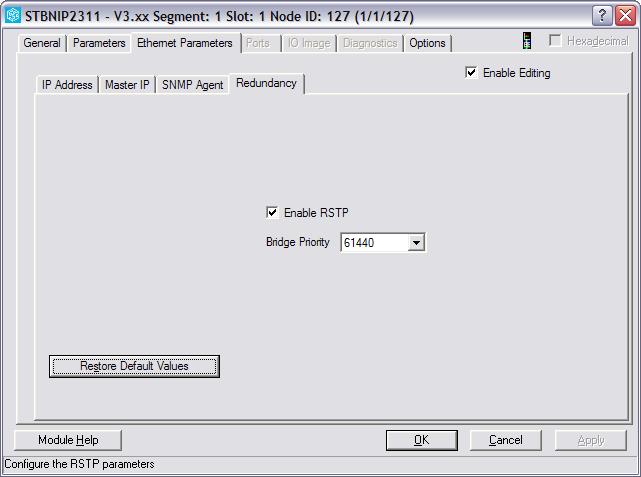
65 4-Configuration The IP addresses A and B are the primary and standby IP addresses (in our case and respectively). The subnet mask must be set to in our application. In the section below, the IP addresses of the drops must be set. In our application, these addresses are to The device names are generated automatically. The RSTP tab must also be configured because our Quantum PACs are RSTP roots on our field network. Therefore, the bridge priority must be set to Root(0). 65
 The Quantum Ethernet modules (NOE) are the modules that manage the Ethernet of the Quantum.")
 NOE2: Ring_2 (Control network 2 for SCADA) NOE3:")
66 4-Configuration Quantum Ethernet modules (NOE) The Quantum Ethernet modules (NOE) are the modules that manage the Ethernet of the Quantum. In our architecture, we have three different networks, which is why each Quantum has three NOEs one for each network. In our case, we have: NOE1: Ring_1 (Control network ring 1 for SCADA) NOE2: Ring_2 (Control network 2 for SCADA) NOE3: Ethernet_Devices (field network) ; this NOE is connected to the CRP Control ring 1 Open the IP Configuration tab and enter for following information: 66

67 4-Configuration IP Address: Subnetwork mask:

68 4-Configuration Control ring 2 Open the IP Configuration tab and enter for following information: IP Address: Subnetwork mask: Field network Open the IP Configuration tab and enter for following information: IP Address: Subnetwork mask:


69 4-Configuration For this network, the module utilities section must be changed so the IO Scanning element must be set to YES. Then open the IO Scanning tab. Following is a list of the DIO clouds devices IP addresses: 69
70 4-Configuration Ethernet switch SW9: STB STB ATV SW ATV71: STB: TESYS T: o STB 1: STB STB STB STB TESYS T TESYS U o STB 2: o STB 3: o STB 4: o STB 5: Ethernet switch SW10: STB ATV71: ATV SW10 STB STB: TESYS T: STB o STB 1: o STB 2: STB TESYS U TESYS T STB STB o STB 3: o STB 4: o STB 5: The configuration window is displayed below: 70

71 4-Configuration Note: New TeSys T modules with double attachment must have the Unit ID configured to configuration The is the counterpart of the CRP on the drop side. In other words, it is the module that receives the commands from the CRP and sends them to the I/O modules of the drop. Open the configuration window of the drop 1: 71

 In a Hot Standby system it is recommended NOT to customize the RPI value.")
72 4-Configuration Following are the parameters that should be configured: In the address information section the device name, IP address and network mask are grayed and cannot be set as they were already configured in the previous section. The Tens and Ones fields should be identical as to what has been physically configured on the (see section ). The Hold up time parameter should be left at its default value (1 second) In a Hot Standby system it is recommended NOT to customize the RPI value. In this case, the RPI value is one quarter of the watchdog time for a cyclic MAST task. The RTSP of the must be configured to Participant as displayed below: 72

73 4-Configuration Repeat these operations for each drop but change the address information according to their physical configuration STB network configuration The DIO clouds network loops use RSTP, so the STB modules have to be configured accordingly using Advantys configuration software. For each STB, the IP address and subnet mask has to be configured in the Ethernet parameters tab as shown below: 73

74 4-Configuration The IP address is different for each STB: Local DIO cloud: STB 1: STB 2: STB 3: STB 4: STB 5: Distant DIO cloud: STB 1: STB 2: STB 3: STB 4: STB 5: For each STB, the RSTP must be enabled and the bridge priority must be set to the value as shown below: 74
75 4-Configuration 75
76 4-Configuration 76
77 5-Implementation 5. Implementation This chapter describes the steps in defining a program for a Hot Standby system using Unity Pro. We will detail the monitoring DFB implementation presented in the Design chapter. The completion of the I/O Device implementation with Vijeo Citect will also be described in this chapter Monitoring Elements in the Primary Section Ethernet Control ring monitoring The Ethernet control ring is managed by a 140 NOE Ethernet communication module. The DFB NOE_Monitor uses the variables structure NOE_Monit to monitor the Ethernet link. The DFB and the variables structure are both presented in the Design chapter NOE_Monitor DFB implementation PRIM_NOE_RING_1 NOE_Monitor PRIM_NOE_RING1.MSTR_act ive MSTR_ACTIVE MSTR_ACTIVE PRIM_NOE_RING1.MSTR_act ive PRIM_NOE_RING1.MSTR_done MSTR_DONE MSTR_DONE PRIM_NOE_RING1.MSTR_done PRIM_NOE_RING1.MSTR_error MSTR_ERROR MSTR_ERROR PRIM_NOE_RING1.MSTR_error PRIM_NOE_RING1.MSTR_RateEt RateEt RateEt PRIM_NOE_RING1.MSTR_RateEt PRIM_NOE_RING1.MSTR_ErrorCount Error_Count Error_Count PRIM_NOE_RING1.MSTR_ErrorCount PRIM_NOE_RING1.MSTR_Cont rol MSTR_Control MSTR_Control MSTR_DataBuf PRIM_NOE_RING1.MSTR_Cont rol PRIM_NOE_RING1.MSTR_Databuf 4 Slot Data_TCP PRIM_NOE_RING1.MSTR_data 2 MonitoringRate LED_APPL PRIM_NOE_RING1.Led_Appl 2 Retries LED_LINK PRIM_NOE_RING1.Led_Link Pulse Pulse LED_RUN PRIM_NOE_RING1.Led_Run NOE_Failure PRIM_NOE_RING1.Failure CFG_PORT PRIM_NOE_RING1.Led_Cfg_Port ETH_100M PRIM_NOE_RING1.Led_Et h_100m OPTICFIB PRIM_NOE_RING1.Led_Opt icfib FULL_DUP PRIM_NOE_RING1.Led_Full_Dup DUP_ADD PRIM_NOE_RING1.DUP_ADD FAULT PRIM_NOE_RING1.Fault EQUP_TYP PRIM_NOE_RING1.EQUIP_TYPE IP_AD_1 IP_AD_2 IP_AD_3 IP_AD_4 MAC_ADD_1 MAC_ADD_2 MAC_ADD_3 MAC_ADD_4 MAC_ADD_5 MAC_ADD_6 PRIM_NOE_RING1.IP_AD_1 PRIM_NOE_RING1.IP_AD_2 PRIM_NOE_RING1.IP_AD_3 PRIM_NOE_RING1.IP_AD_4 PRIM_NOE_RING1.MAC_AD_1 PRIM_NOE_RING1.MAC_AD_2 PRIM_NOE_RING1.MAC_AD_3 PRIM_NOE_RING1.MAC_AD_4 PRIM_NOE_RING1.MAC_AD_5 PRIM_NOE_RING1.MAC_AD_6 77
78 5-Implementation Step Action 1 Instantiate the DFB NOE_Monitor under the name PRIM_NOE_RING_1 2 Instantiate the variables structure NOE_Monit under the name PRIM_NOE_CTRL 3 Connect the variables of the structure on the DFB pins For the pin named Slot, enter the value 4. This corresponds to the NOE module slot number in the hardware configuration On the Pulse pin connect the variable pulse computed at the beginning of the primary section. This pulse indicates each cycle beginning. For the pin named Monitoring Rate, enter the value 2. This means that the local statistics are extracted from the MBP_MSTR function every two cycles For the pin named Retries, enter the value 2. This corresponds to the maximum number of unsuccessful attempts at extracting the local statistics from the MBP_MSTR that will be tolerated before issuing an exception response Devices Ethernet Ring Monitoring The devices Ethernet ring is also managed by a 140 NOE Ethernet communication module. Just as with the Ethernet control ring, the DFB NOE_Monitor uses the variables structure NOE_Monit to monitor the Ethernet link. 78
79 5-Implementation PRIM_NOE_DEV NOE_Monitor PRIM_NOE_DEVICES.MSTR_act ive MSTR_ACTIVE MSTR_ACTIVE PRIM_NOE_DEVICES.MSTR_act ive PRIM_NOE_DEVICES.MSTR_done MSTR_DONE MSTR_DONE PRIM_NOE_DEVICES.MSTR_done PRIM_NOE_DEVICES.MSTR_error MSTR_ERROR MSTR_ERROR PRIM_NOE_DEVICES.MSTR_error PRIM_NOE_DEVICES.MSTR_Rat eet RateEt RateEt PRIM_NOE_DEVICES.MSTR_Rat eet PRIM_NOE_DEVICES.MSTR_ErrorCount Error_Count Error_Count PRIM_NOE_DEVICES.MSTR_ErrorCount PRIM_NOE_DEVICES.MSTR_Control MSTR_Control MSTR_Control MSTR_DataBuf PRIM_NOE_DEVICES.MSTR_Control PRIM_NOE_DEVICES.MSTR_Dat abuf 6 Slot Data_TCP PRIM_NOE_DEVICES.MSTR_dat a 2 MonitoringRate LED_APPL PRIM_NOE_DEVICES.Led_Appl 2 Retries LED_LINK PRIM_NOE_DEVICES.Led_Link Pulse Pulse LED_RUN PRIM_NOE_DEVICES.Led_Run NOE_Failure PRIM_NOE_DEVICES.Failure CFG_PORT PRIM_NOE_DEVICES.Led_Cfg_Port ETH_100M PRIM_NOE_DEVICES.Led_Et h_100m OPTICFIB PRIM_NOE_DEVICES.Led_Opt icfib FULL_DUP PRIM_NOE_DEVICES.Led_Full_Dup DUP_ADD PRIM_NOE_DEVICES.DUP_ADD FAULT PRIM_NOE_DEVICES.Fault EQUP_TYP PRIM_NOE_DEVICES.EQUIP_TYPE IP_AD_1 IP_AD_2 IP_AD_3 IP_AD_4 MAC_ADD_1 MAC_ADD_2 MAC_ADD_3 MAC_ADD_4 MAC_ADD_5 MAC_ADD_6 PRIM_NOE_DEVICES.IP_AD_1 PRIM_NOE_DEVICES.IP_AD_2 PRIM_NOE_DEVICES.IP_AD_3 PRIM_NOE_DEVICES.IP_AD_4 PRIM_NOE_DEVICES.MAC_AD_1 PRIM_NOE_DEVICES.MAC_AD_2 PRIM_NOE_DEVICES.MAC_AD_3 PRIM_NOE_DEVICES.MAC_AD_4 PRIM_NOE_DEVICES.MAC_AD_5 PRIM_NOE_DEVICES.MAC_AD_6 Step Action 1 Instantiate the DFB NOE_Monitor under the name PRIM_NOE_DEV 2 Instantiate the variables structure NOE_Monit under the name PRIM_NOE_DEVICES located in the non-transfer area 3 Connect the variables from the structure on the DFB pins 4 For the pin named Slot, enter the value 6 5 For the pin named Monitoring Rate, enter the value 2 6 For the pin named Retries, enter the value 2 To manage the Hot Standby system, the FAULT output of this DFB is used as an input in the Fault synthesis. This operation is described in section
80 5-Implementation Monitoring Rate Pulse In order to control the NOE_Monitor block monitoring rate (execution of the MBP_MSTR function), a pulse signal is implemented. This pulse signal is a trigger at the beginning of each program cycle.the monitoring rate varies according to the cycle length of the application. R_TRIG HSBY_ST EN ENO CLK Q Pulse HSBY THIS_OFF HSBY_CONF_OK THIS_OFFLINE INC GT THIS_PRY THIS_PRIMARY EN ENO EN ENO MOVE THIS_SBY THIS_STANDBY CycleNb INOUT INOUT CycleNb CycleNb IN1 OUT EN ENO REMT_OFF REMOTE_OFFLINE 1 IN2 0 CLK Q CycleNb REMT_PRY REMOTE_PRIMARY REMT_SBY REMOTE_STANDBY LOGIC_OK THIS_ISA THIS_ISB Fault Synthesis The fault synthesis comprises two parts. Firstly, a synthesis of the NOE module faults is performed. Then, a faults synthesis is performed using a mask that makes it possible to inhibit specific faults. To implement this synthesis, we use the DFBs presented in the Design chapter: SYNTH_OR_NOE and SYNTH_FAULT. The aim from the NOE side is to cause the following behavior: If one of the two Control networks is lost, then the system will switch over to the other control network If both control networks are lost, then the system will switch to the other Quantum If the DIO network is lost, then the system will switch to the other Quantum 80
81 5-Implementation PRIM_NOE_SCADA_FAULT_SYNTH SYNTH_AND_NOE PRIM_NOE_RING1_Fault FLT_NOE_1 FAULT_NOE PRIM_NOE_RING2_Fault FLT_NOE_2 False FLT_NOE_3 False FLT_NOE_4 False FLT_NOE_5 False FLT_NOE_6 PRIM_NOE_FAULT_SYNTH SYNTH_OR_NOE False PRIM_NOE_DEVICES_Fault False False False FLT_NOE_1 FLT_NOE_2 FLT_NOE_3 FLT_NOE_4 FLT_NOE_5 FLT_NOE_6 FAULT_NOE PRIM_SYNTH_FAULT SYNTH_FAULT False False 2#0000_1100_0111_1111 Fault y_noe Fault y_ptq Fault y_scada Fault_Mask Fault_Synth Fault PRIM_SYNTH_FLT_PLC PRIM_FAULT_PLC Part 1: NOE Synthesis Step Action Instantiate the DFB SYNTH_AND_NOE under the name PRIM_NOE_SCADA_FAULT_SYNTH Connect the variable PRIM_NOE_CTRL_FAULT previously computed by the PRIM_NOE_RING1 DFB on the pin FLT_NOE_1 Connect the variable PRIM_NOE_CTRL_FAULT previously computed by the PRIM_NOE_RING1 DFB on the pin FLT_NOE_2 4 Connect a False variable (unlocated) on all the other pins Part 2: NOE Synthesis Step Action Instantiate the DFB SYNTH_OR_NOE under the name PRIM_NOE_FAULT_SYNTH On the pin FLT_NOE_1, connect the output of the block described in part 1 above Connect the variable PRIM_NOE_DEVICES_FAULT previously computed by the PRIM_NOE_DEV DFB on the pin FLT_NOE_3 81
82 5-Implementation Step Action 4 Connect a False variable (unlocated) on all the other pins Part 3: FAULT Synthesis Step Action Instantiate the DFB SYNTH_FAULT under the name PRIM_SYNTH_FAULT Link the input pin Faulty_NOE to the output pin Fault_NOE of the PRIM_NOE_FAULT_SYNTH DFB On the Faulty_PTQ pin, connect a False variable. Our application does not include blocks dedicated to PTQ On the Faulty_Scada pin, connect a False variable. Our application does not include blocks dedicated to SCADA system monitoring We now need to define which event will initiate a switchover. The table below is used to compose the mask and define the monitoring filter to apply as an input of the DFB. The mask value to be set on the Fault_Mask pin is 2# Bit Elements Fault Mask Definition Bit 0 Battery fault 1 Bit 1 CPU fault 1 Bit 2 General I/O rack fault 1 Bit 3 Fault on slot 3 1 Bit 4 Fault on slot 4 1 Bit 5 Fault on slot 5 1 Bit 6 Fault on slot 6 1 Bit 7 Fault on slot 7 0 Bit 8 Fault on slot 8 0 Bit 9 Fault on slot 9 0 Bit 10 Fault on slot 10 1 Bit 11 Ethernet Adapter(s) NOE Fault 1 Bit 12 Profibus DP Adapter(s) Fault 0 Bit 13 SCADA Fault 0 Bit 14-0 Bit
83 5-Implementation Step 6 7 Action On the Fault_Synth pin, connect the variable RIM_SYNTH_FLT_PLC located in the non-transfer area. This word represents the Primary configuration Fault synthesis after the Fault_Mask filter. It will be used in the determination of the switchover. On the Fault pin, connect the variable PRIM_FAULT_PLC located in the non-transfer area. This Boolean information indicates a fault detection after the Fault_Mask filter Monitoring Elements in the Standby Section In this section, which is the only one executed by the Standby PAC, we find the same elements as in the Primary Section Controller Ethernet Ring Monitoring DFB NOE_Monitor implementation: STBY_NOE_RING_1 NOE_Monitor %SW61.0 EN STBY_NOE_RING1.MSTR_act ive MSTR_ACTIVE MSTR_ACTIVE STBY_NOE_RING1.MSTR_act ive STBY_NOE_RING1.MSTR_done MSTR_DONE MSTR_DONE STBY_NOE_RING1.MSTR_done STBY_NOE_RING1.MSTR_error MSTR_ERROR MSTR_ERROR STBY_NOE_RING1.MSTR_error STBY_NOE_RING1.MSTR_RateEt RateEt RateEt STBY_NOE_RING1.MSTR_RateEt STBY_NOE_RING1.MSTR_ErrorCount Error_Count Error_Count STBY_NOE_RING1.MSTR_ErrorCount STBY_NOE_RING1.MSTR_Cont rol MSTR_Control MSTR_Control MSTR_DataBuf STBY_NOE_RING1.MSTR_Cont rol STBY_NOE_RING1.MSTR_Dat abuf 4 Slot Data_TCP STBY_NOE_RING1.MSTR_dat a 2 MonitoringRate LED_APPL STBY_NOE_RING1.Led_Appl 2 Retries LED_LINK STBY_NOE_RING1.Led_Link Pulse Pulse LED_RUN STBY_NOE_RING1.Led_Run NOE_Failure STBY_NOE_RING1.Failure CFG_PORT STBY_NOE_RING1.Led_Cfg_Port ETH_100M STBY_NOE_RING1.Led_Et h_100m OPTICFIB STBY_NOE_RING1.Led_Opt icfib FULL_DUP STBY_NOE_RING1.Led_Full_Dup DUP_ADD STBY_NOE_RING1.DUP_ADD FAULT STBY_NOE_RING1.Fault EQUP_TYP STBY_NOE_RING1.EQUIP_TYPE IP_AD_1 IP_AD_2 IP_AD_3 IP_AD_4 MAC_ADD_1 MAC_ADD_2 MAC_ADD_3 MAC_ADD_4 MAC_ADD_5 MAC_ADD_6 STBY_NOE_RING1.IP_AD_1 STBY_NOE_RING1.IP_AD_2 STBY_NOE_RING1.IP_AD_3 STBY_NOE_RING1.IP_AD_4 STBY_NOE_RING1.MAC_AD_1 STBY_NOE_RING1.MAC_AD_1 STBY_NOE_RING1.MAC_AD_2 STBY_NOE_RING1.MAC_AD_3 STBY_NOE_RING1.MAC_AD_4 STBY_NOE_RING1.MAC_AD_5 STBY_NOE_RING1.MAC_AD_6 Step Action 83
84 5-Implementation Step 1 2 Action Instantiate the DFB NOE_Monitor under the name STDBY_NOE_RING_1 Instantiate a new structure NOE_Monit under the name STBY_NOE_CTRL 3 Connect the structure variables on the pins of the DFB 4 On the pin Slot, enter the value 4 (position of the NOE module on the rack) 5 On the pin Monitoring Rate, enter the value 2 6 On the pin Retries, enter the value 2 7 To verify that only the Standby PAC executes this block, we add a condition on its execution. Right click on the block and select Properties 8 9 Check the box Show EN/ENO. This enables a pin EN as input of the DFB and a pin ENO as output. On the pin EN, connect the bit 0 of the status register %SW61. This indicates whether the PAC is Primary or Standby Devices Ethernet Ring Monitoring DFB NOE_Monitor implementation: 84
85 5-Implementation STBY_NOE_DEV NOE_Monitor %SW61.0 EN STBY_NOE_DEVICES.MSTR_act ive MSTR_ACTIVE MSTR_ACTIVE STBY_NOE_DEVICES.MSTR_act ive STBY_NOE_DEVICES.MSTR_done MSTR_DONE MSTR_DONE STBY_NOE_DEVICES.MSTR_done STBY_NOE_DEVICES.MSTR_error MSTR_ERROR MSTR_ERROR STBY_NOE_DEVICES.MSTR_error STBY_NOE_DEVICES.MSTR_Rat eet RateEt RateEt STBY_NOE_DEVICES.MSTR_Rat eet STBY_NOE_DEVICES.MSTR_ErrorCount Error_Count Error_Count STBY_NOE_DEVICES.MSTR_ErrorCount STBY_NOE_DEVICES.MSTR_Cont rol MSTR_Control MSTR_Control MSTR_DataBuf STBY_NOE_DEVICES.MSTR_Cont rol STBY_NOE_DEVICES.MSTR_Dat abuf 6 Slot Data_TCP STBY_NOE_DEVICES.MSTR_dat a 2 MonitoringRate LED_APPL STBY_NOE_DEVICES.Led_Appl 2 Retries LED_LINK STBY_NOE_DEVICES.Led_Link Pulse Pulse LED_RUN STBY_NOE_DEVICES.Led_Run NOE_Failure STBY_NOE_DEVICES.Failure CFG_PORT STBY_NOE_DEVICES.Led_Cfg_Port ETH_100M STBY_NOE_DEVICES.Led_Et h_100m OPTICFIB STBY_NOE_DEVICES.Led_Opt icfib FULL_DUP STBY_NOE_DEVICES.Led_Full_Dup DUP_ADD STBY_NOE_DEVICES.DUP_ADD FAULT STBY_NOE_DEVICES.Fault EQUP_TYP STBY_NOE_DEVICES.EQUIP_TYPE IP_AD_1 IP_AD_2 IP_AD_3 IP_AD_4 IP_AD_1 MAC_ADD_1 MAC_ADD_2 MAC_ADD_3 MAC_ADD_4 MAC_ADD_5 MAC_ADD_6 STBY_NOE_DEVICES.IP_AD_1 STBY_NOE_DEVICES.IP_AD_2 STBY_NOE_DEVICES.IP_AD_3 STBY_NOE_DEVICES.IP_AD_4 STBY_NOE_DEVICES.MAC_AD_1 STBY_NOE_DEVICES.MAC_AD_1 STBY_NOE_DEVICES.MAC_AD_2 STBY_NOE_DEVICES.MAC_AD_3 STBY_NOE_DEVICES.MAC_AD_4 STBY_NOE_DEVICES.MAC_AD_5 STBY_NOE_DEVICES.MAC_AD_6 85
86 5-Implementation Step Action 1 Instantiate the DFB NOE_Monitor under the name STDBY_NOE_DEV 2 Instantiate a new structure NOE_Monit under the name STBY_NOE_DEVICES located in the non-transfer area 3 Connect the structure variables on the pins of the DFB 4 On the pin Slot, enter the value 6 5 On the pin Monitoring Rate, enter the value 2 6 On the pin Retries, enter the value 2 7 Repeat the preceding steps for the block execution and connect the bit 0 of the status register %SW61 on the pin EN As with the Primary Section, the FAULT output of this DFB is used as an input in the Fault synthesis Fault Synthesis In the standby section, the expected behavior is the same as in the primary section, but the fact that the Quantum is standby must be taken into account. This is done using the system word %SW61. STBY_NOE_SCADA_FAULT_SYNTH SYNTH_AND_NOE %SW61.0 EN STBY_NOE_RING1_Fault FLT_NOE_1 FAULT_NOE STBY_NOE_RING2_Fault FLT_NOE_2 False FLT_NOE_3 False FLT_NOE_4 False FLT_NOE_5 False FLT_NOE_6 STBY_NOE_FAULT_SYNTH %SW61.0 False STBY_NOE_DEVICES_Fault False False False SYNTH_OR_NOE EN FLT_NOE_1 FAULT_NOE FLT_NOE_2 FLT_NOE_3 FLT_NOE_4 FLT_NOE_5 FLT_NOE_6 STBY_SYNTH_FAULT %SW61.0 False False 2#0000_1100_0111_1111 SYNTH_FAULT EN Fault y_noe Fault y_ptq Fault y_scada Fault_Mask Fault_Synth Fault STBY_SYNTH_FLT_PLC STBY_FAULT_PLC 86
87 5-Implementation Part 1: NOE SCADA Synthesis Step Action Instantiate the DFB SYNTH_AND_NOE under the name STDBY_NOE_SCADA_FAULT_SYNTH On the pin FLT_NOE_1, connect the variable STBY_NOE_CTRL_FAULT previously computed by the DFB STBY_NOE_RING1 On the pin FLT_NOE_2, connect the variable STBY_NOE_DEVICES_FAULT previously computed by the DFB STBY_NOE_RING2 4 Connect a False variable (unlocated) on all the other pins Part 2: NOE Synthesis Step Action Instantiate the DFB SYNTH_OR_NOE under the name STDBY_NOE_FAULT_SYNTH On the pin FLT_NOE_1, connect the output of the block described in part 1 above On the pin FLT_NOE_3, connect the variable STBY_NOE_DEVICES_FAULT previously computed by the DFB STBY_NOE_DEV 4 Connect a False variable (unlocated) on all the other pins Part 3: FAULT Synthesis Step Action Instantiate the DFB SYNTH_FAULT under the name STDBY_SYNTH_FAULT Link the input pin Faulty_NOE to the output pin Fault_NOE of the DFB STDBY_NOE_FAULT_SYNTH On the Faulty_PTQ pin, connect a False variable. Our application does not include blocks dedicated to PTQ On the Faulty_Scada pin, connect a False variable. Our application does not include blocks dedicated to SCADA system monitoring Set the Fault_Mask value with the same value as the Primary section, which is 2#
88 5-Implementation Step Action On the Fault_Synth output pin, connect the variable STBY_SYNTH_FLT_PLC. This word represents the Standby configuration Fault synthesis after the Fault_Mask filter. It will be used in the determination of the switchover. Therefore, this variable is located on the reverse register %SW62 that allows writing from Standby to Primary On the Fault pin, connect the variable STBY_FAULT_PLC located in the non-transfer area. This Boolean information indicates a fault detection after the Fault_Mask filter For each of these blocks, activate the execution option and connect the bit 0 of the status register %SW61 on the pin EN Switchover Management Once the monitoring DFB is implemented and the fault synthesis is computed in the Primary and Standby sections, it is necessary to process the obtained data and to set the switchover management rules. To set the management rules we use the DFB Switch_Manag previously described in the Design chapter. This DFB is instantiated in the Primary section. DFB Switch_Manag implementation: HSBY_SWITCH SWITCH_MANAG PRIM_SYNTH_FLT_PLC STBY_SYNTH_FLT_PLC PRIM_DIAG STBY_DIAG Swit ch_nb_reset SWITCH_NB_Reset SWITCH_NB Swit ch_nb Force_Switchover FORCE FORCE Force_Switchover Step Action 1 Instantiate the DFB SWITCH_MANAG under the name HSBY_SWITCH Connect the variable PRIM_SYNTH_FLT_PLC (Primary PAC Fault synthesis) on the pin PRIM_DIAG Connect the variable STBY_SYNTH_FLT_PLC (Standby PAC Fault synthesis) on the pin STBY_DIAG Connect a variable Switch_Nb_Reset, located in the non-transfer area, on the Switch_Nb_Reset pin 88


89 5-Implementation Step Action 5 Connect a variable Force_Switchover on the pin FORCE 6 On the output pin Switch_NB, connect a variable Switch_NB located in the non-transfer area 5.4. SCADA The management of the Ethernet redundant links of the Quantum Hot Standby system is now complete OFS variables import This section describes how to automatically link the variable tags from OFS to Vijeo Citect using the variables import in Vijeo Citect. In Citect Explorer, open the Tools menu and select Import tags. The following window is opened: In the Destination section, the field I/O Device should be set to IO_DEVICE_QUANT. 89

90 5-Implementation In the Source section, set the database type to Unity SpeedLink to OFS. Then select the external database using the Browse button. The following window opens: Select OFS_QUANTUM_1 and click OK to validate and close the window. The import variable tags window should now have the connection string field with the value automatically set. 90
 of the primary Quantum Display of the")
91 5-Implementation Click the Import button to finalize the operation User interface Using Vijeo Citect, we designed a user interface with the following information and controls: Status of the system registers (%SW60 and %SW61) of the primary Quantum Display of the primary PAC (A or B) Effective scan time of the primary PAC Number of switchovers and the associated reset button A button to force an applicative switchover 91
92 5-Implementation When communication with the primary PAC is lost which happens in case of switchover, for example the information is grayed as shown below: 92
93 5-Implementation 93
94 6-Validation 6. Validation 6.1. Functional tests This chapter describes the various tests we performed on the different architectures used for this document. The first section describes the functional tests, where the general behavior of the system is compared to the expected behavior when given a certain stimulus. The second section describes the performance tests, including information on the time needed for different configurations of the system to perform specific operations. In this section we check that the system behaves correctly when exposed to some specific changes in functionality and describes the functional tests. We grouped the tests into three categories: - The Quantum failure tests check that the hot standby Quantum takes control of the system when the primary Quantum fails - The Quantum cable break tests verify the behavior of the system when Ethernet cables are cut, taking into account the specific libraries we implemented - The SCADA perturbations tests show how the SCADA system reacts to server stops or cable breaks The results of all tests are summarized in section Quantum failure In this section different conditions of failure of the Quantum are tested, including loss of power supply, CPU, CRP and NOE failures. Power supply down on primary Quantum Action: shutdown primary Quantum power supply. 94
95 6-Validation Expected behavior: hot-standby Quantum takes control of the system (switchover). System-built-in function: yes. No additional code must be implemented for this feature. CPU failure on primary Quantum Action: the CPU block of the primary Quantum is unplugged. Expected behavior: hot-standby Quantum takes control of the system (switchover). System-built-in function: yes. No additional code must be implemented for this feature. CRP failure on primary Quantum Action: the CRP of the primary Quantum is unplugged. 95
 of the primary Quantum is unplugged. Expected behavior: hot-standby Quantum takes control of the system (switchover).")
96 6-Validation Expected behavior: hot-standby Quantum takes control of the system (switchover). System-built-in function: yes. No additional code must be implemented for this feature. NOE1 failure on primary Quantum Action: the NOE1 (control ring 1) of the primary Quantum is unplugged. Expected behavior: hot-standby Quantum takes control of the system (switchover). System-built-in function: no. We implemented this behavior in our application, see section NOE2 failure on primary Quantum Action: the NOE2 (control ring 2) of the primary Quantum is unplugged. 96
97 6-Validation Expected behavior: hot-standby Quantum takes control of the system (switchover). System-built-in function: no. We implemented this behavior in our application, see section NOE3 failure on primary Quantum Action: the NOE3 (DIO clouds on field network) of the primary Quantum is unplugged. Expected behavior: hot-standby Quantum takes control of the system (switchover). System-built-in function: no. We implemented this behavior in our application, see section Quantum cable breakages In this section, the tests concern different cases of Ethernet cable breakages on the different networks main loop of the field network, control rings (on the Quantum side), and field network on the DIO side. Cable break on field network (main loop) Action: the Ethernet cable between the primary Quantum and the Ethernet switch SW11 (field network main loop) is broken. 97
98 6-Validation PRIMARY SERVER VIJEO CITECT CLIENT STANDBY SERVER SW1 SW2 SW4 SW5 SW6 SW3 NOE1 NOE2 NOE3 CRP NOE1 NOE2 NOE3 CRP PRIMARY QUANTUM SW7 SW8 STANDBY QUANTUM SW11 SW12 SW9 DROP 1 DROP 4 SW10 DROP 2 DROP 5 DROP 3 DROP 6 Expected behavior: the network switches and the Ethernet data uses an alternate route. System-built-in function: yes. No additional code must be implemented for this feature. Quantum cable break on control ring 1 Action: the cable between the primary Quantum and the Ethernet switch SW3 (control ring 1) is broken. 98
99 6-Validation PRIMARY SERVER VIJEO CITECT CLIENT STANDBY SERVER SW1 SW2 SW4 SW5 SW6 SW3 NOE1 NOE2 NOE3 CRP NOE1 NOE2 NOE3 CRP PRIMARY QUANTUM SW7 SW8 STANDBY QUANTUM SW11 SW12 SW9 DROP 1 DROP 4 SW10 DROP 2 DROP 5 DROP 3 DROP 6 Expected behavior: The Quantum and the SCADA system communicate using the control ring 2. System-built-in function: no. We implemented this behavior in our application, see section Quantum cable break on both control rings Action: the cable between the primary Quantum and the Ethernet switch SW3 (control ring 1) is broken and the cable between the primary Quantum and the Ethernet switch SW4 (control ring 2) is broken. 99
100 6-Validation PRIMARY SERVER VIJEO CITECT CLIENT STANDBY SERVER SW1 SW2 SW4 SW5 SW6 SW3 NOE1 NOE2 NOE3 CRP NOE1 NOE2 NOE3 CRP PRIMARY QUANTUM SW7 SW8 STANDBY QUANTUM SW11 SW12 SW9 DROP 1 DROP 4 SW10 DROP 2 DROP 5 DROP 3 DROP 6 Expected behavior: hot-standby Quantum takes control of the system (switchover). System-built-in function: no. We implemented this behavior in our application, see section Cable break on field network (DIO clouds) Action: the cable between the NOE3 and the CRP on the primary Quantum is broken. 100
101 6-Validation PRIMARY SERVER VIJEO CITECT CLIENT STANDBY SERVER NOE1 NOE2 NOE3 CRP NOE1 NOE1 NOE2 NOE2 NOE3 NOE3 CRP CRP SW1 SW2 SW4 SW5 SW6 SW3 PRIMARY QUANTUM SW7 SW8 STANDBY QUANTUM SW11 SW12 SW9 DROP 1 DROP 4 SW10 DROP 2 DROP 5 DROP 3 DROP 6 Expected behavior: hot-standby Quantum takes control of the system (switchover). System-built-in function: no. We implemented this behavior in our application, see section
102 6-Validation SCADA perturbations In this section the behavior of the SCADA system is studied when the following perturbations occur: the I/O server (i.e. the service) is stopped, a different cable breaks on the server side, and shutdown of the primary server (i.e. the physical computer that runs the services). The priorities set to the different servers in the SCADA configuration are mostly responsible for the behavior of the SCADA system. I/O server A down Action: I/O server A on the primary server is shutdown (service is stopped). PRIMARY SERVER VIJEO CITECT CLIENT STANDBY SERVER SW1 SW2 SW4 SW5 SW6 SW3 NOE1 NOE2 NOE3 CRP NOE1 NOE2 NOE3 CRP PRIMARY QUANTUM SW7 SW8 STANDBY QUANTUM SW11 SW12 SW9 DROP 1 DROP 4 SW10 DROP 2 DROP 5 DROP 3 DROP 6 Expected behavior: I/O server B takes control of the SCADA process; alarms, trends and reports servers, which usually run on server A. System-built-in function: no. This behavior is configured in Vijeo Citect; for more details, see section
103 6-Validation Port A1 cable break Action: the cable between the primary server and Ethernet switch SW1 (control ring 1) is broken. PRIMARY SERVER VIJEO CITECT CLIENT STANDBY SERVER SW1 SW2 SW4 SW5 SW6 SW3 NOE1 NOE2 NOE3 CRP NOE1 NOE2 NOE3 CRP PRIMARY QUANTUM SW7 SW8 STANDBY QUANTUM SW11 SW12 SW9 DROP 1 DROP 4 SW10 DROP 2 DROP 5 DROP 3 DROP 6 Expected behavior: server A switches to port A2 and uses control ring 2. System-built-in function: no. This behavior is configured in Vijeo Citect; for more details, see section
104 6-Validation Power supply down on server A Action: server A is shutdown (the computer is stopped) PRIMARY SERVER VIJEO CITECT CLIENT STANDBY SERVER SW1 SW2 SW4 SW5 SW6 SW3 NOE1 NOE2 NOE3 CRP NOE1 NOE2 NOE3 CRP PRIMARY QUANTUM SW7 SW8 STANDBY QUANTUM SW11 SW12 SW9 DROP 1 DROP 4 SW10 DROP 2 DROP 5 DROP 3 DROP 6 Expected behavior: server B takes control of the SCADA processes (I/O server and ATR servers) using port B1 (control ring 1). System-built-in function: no. This behavior is configured in Vijeo Citect; for more details, see section
105 6-Validation Server A is down and port B1 cable break Action: server A is shutdown (the computer is stopped) and the cable between the standby server and Ethernet switch SW2 (control ring 1) is broken. PRIMARY SERVER VIJEO CITECT CLIENT STANDBY SERVER SW1 SW2 SW4 SW5 SW6 SW3 NOE1 NOE2 NOE3 CRP NOE1 NOE2 NOE3 CRP PRIMARY QUANTUM SW7 SW8 STANDBY QUANTUM SW11 SW12 SW9 DROP 1 DROP 4 SW10 DROP 2 DROP 5 DROP 3 DROP 6 Expected behavior: server B takes control of all SCADA processes (I/O server and ATR servers) using port B2 (control ring 2). System-built-in function: no. This behavior is configured in Vijeo Citect; for more details, see section
106 6-Validation Functional tests results The table below summarizes the results of all the functional tests: cat. Test description Expected result Actual result Test pass Power supply down on primary Quantum Quantum switchover Quantum switchover OK Quantum switchover CPU failure on primary Quantum CRP unplugged on primary Quantum NOE1 unplugged on primary Quantum NOE2 unplugged on primary Quantum Quantum switchover Quantum switchover Quantum switchover Quantum switchover Quantum switchover Quantum switchover Quantum switchover Quantum switchover OK OK OK OK NOE3 unplugged Quantum switchover Quantum switchover OK SCADA perturbations Quantum cable breaks Quantum cable break on field network (main loop) Quantum cable break on control ring 1 Quantum cable break on both control rings Cable break on field network (DIO clouds) I/O server A down Port A1 cable break Power supply down on server A Server A is down and port B1 cable break network reconfiguration SCADA ring 2 is used Quantum switchover Quantum switchover I/O server switchover Server A switches to ring 2 SCADA server switchover Server B switches to ring 2 network reconfiguration SCADA ring 2 is used Quantum switchover Quantum switchover I/O server switchover Server A switches to ring 2 SCADA server switchover Server B switches to ring 2 OK OK OK OK OK OK OK OK 106
 The switchover time of the PAC units Additional tools we used for our tests are: Schneider Electric Modicon M340 PAC")
107 6-Validation 6.2. Performance tests In this section we cover the performance tests we executed on our selected architectures. Following is a list of our tests: Impact of the application response time (ART) The switchover time of the PAC units Additional tools we used for our tests are: Schneider Electric Modicon M340 PAC DIG_OUT This PAC is used with a digital I/O module so that we can drive cable breakers Hilscher netanalyzer This device can analyze and record Ethernet traffic, it can also manage physical digital inputs and t is very accurate its time-stamp has a resolution of 10 nanoseconds. The table below shows the different parameters that were changed during our tests, and the different values that we used: Cyclic scan time (ms) Data size (kb) Architecture and measurement type RCE EIO RFD EIO RFD DIO RCE EIO: Redundant Compact Evolutive architecture, measurements done on Ethernet remote I/Os RFD EIO: Redundant Flexible Distributed architecture, measurements done on Ethernet remote I/Os RFD DIO: Redundant Flexible Distributed architecture, measurements done on Distributed I/Os 107
108 6-Validation Hot Standby system application response time The application response time (ART) is the time taken for information to be recognized by the system, and then for the system to react. Following is a description of the different steps of this measurement type: 1 DI signal A physical signal is sent to the remote module on a digital input; this is the start time of the measurement 2 Ethernet transmission The remote module sends the corresponding information to the Quantum 3 Computation The Quantum CPU handles the input information and sends a command to an output 4 Ethernet transmission The Quantum sends the corresponding information to the remote module 5 DO signal The remote module processes the physical digital output; this is the stop time of the measurement The ART is the time taken for all the steps described in the table above to be completed. Note: In the table above, the remote module is represented as an Ethernet drop, but the principle of the measurement is the same with distributed I/O modules or any system with inputs and outputs. More specific figures for the tested hardware will be described in the following sub-sections. All ART measurements are completed with 108
109 6-Validation the Quantum A as the primary PAC, and the Quantum B as the standby PAC and running. Each test was performed at least one thousand times. Ethernet remote I/O ART with Redundant Compact Evolutive architecture Using the Redundant Compact Evolutive architecture (the architecture without DIO) and the Redundant Flexible Distributed architecture (the architecture with DIO, although we did not use them for this test) we measured the ART with the digital input and the digital output on drops, as shown in the following figure: SW11 SW12 Optical fiber (10km) LOCAL DROPs DROP 1 DROP 2 To Digital Input DIG_OUT Start signal DROP 4 DROP 5 DISTANT DROPs Net Analyzer DROP 3 Stop signal DROP 6 From Digital Output Distributed I/O ART with Redundant Flexible Distributed architecture Using the Redundant Flexible Distributed architecture (the architecture with DIO devices) we measured the ART with the digital input and the digital output on an STB, as shown in the following figure: M340 DIG_OUT DIG_IN STB 1 To Digital Input Start signal STB 11 DISTANT DEVICES STB 12 LOCAL DEVICES STB 2 STB 13 STB 3 Net Analyzer STB 14 STB 4 From Digital Output Stop signal STB 15 STB 5 109
110 6-Validation Theoretical maximum ART for QEIO solutions The application response time is covered more specifically in a separate TVDA, Quantum EIO design, that details the theoretical times. In this TVDA, we concentrate our tests on the hot standby features. In the first instance we can consider that: Note: The added is a constant value in milliseconds representing the maximum network process time. This constant applies to all our architectures. A hot standby system has an extended cycle time because: - Extra time is needed for the data to transfer to the coprocessor ( which is proportional to the data size) - Extra time might be needed if the coprocessor time is longer than the user logic More details on this topic are available in section Allowing for the above, the complete formula can be modified with: Note: The orange text in this formula represents the extra time needed for the hot standby feature. The green text represents the time linked to the MAST. Therefore, we can deduce the total formula of the ART: 110
111 6-Validation Below is a diagram of the different actions that explain some of the parameters of the above formula: CPU state Quantum A in acq hsby transfer hsby transfer hsby prog exec out update in acq hsby prog exec primary run out update A measurement B C This diagram shows that, depending on the moment at which the input data arrives to the PAC on the network, there can be up to two MAST cycles before the output is sent to the network i.e. the data arrives at the CRP (A), it is stored in a buffer until the next input acquisition cycle of the CPU (B). At the end of the MAST, the output is sent to the CRP (C). The RPI is the period at which the sends the data to the CRP. Therefore the RPI and the network transmission times are added to get the total maximum time. Note: When using a DIO solution instead of Ethernet RIO, the ART is not guaranteed. Therefore, there is no theoretical value. Influence of different architectures Below is a table summarizing the results of our ART tests 1000 per configuration based on the relevant architecture, using a 200 ms cyclic scan time and 500 kb of data: System configuration ART Measurements calculated Architecture I/O type RPI min time avg. time max time std. dev. dev. % max time RCE EIO RFD DIO RCE: Redundant Compact Evolutive architecture RFD: Redundant Flexible Distributed architecture 111
112 6-Validation The measurements performed on the EIO are the same, so the presence of the DIO clouds does not influence the performance of the EIO system. The measurements performed on the DIO are slightly better because the repeating time on the DIO is 62ms, which is shorter than the 125 ms RPI on the EIO. In all cases, the measured standard deviation is about twenty percent. This means that: - 68% of the ART are between ART avg 20% and ART avg + 20% - 95% of the ART are between ARTavg 40% and ART avg + 40% The next sections show this information in graphics. Influence of scan time Below are the results of our ART tests 1000 per configuration when considering the influence of the scan time; these tests were performed on the RCE architecture on EIO with 500 kb of data. System configuration ART Measurements calculated Cyclic scan time Watchdog RPI min time avg. time max time std. dev. dev. % max time ART (ms) Average Std. Dev. 2 x Std. Dev. Calc. Max cyclic scan time (ms) The colored curves in the above graph correspond to the following: - The top red curve represents the calculated maximum ART - The middle orange curve shows the average measurement 112
113 6-Validation - The blue curves are one standard deviation distant from the average, which is 68 per cent of the measurements are between these curves - The green curves are two standard deviations distant from the average, which is 95 per cent of the measurements are between these curves The system behaves as expected the ART increases with the scan time and the standard deviation is about twenty per cent. Influence of data size Below are the results of our ART tests 1000 per configuration when considering the influence of the data size. These tests were performed on the RCE architecture on EIO with a 100 ms cyclic scan time. System ART Measurements calculated Data (kb) min time avg. time max time std. dev. dev. % max time ART (ms) data (kb) Average Std. Dev. 2 x Std. Dev. Calc. Max The colored curves correspond to the following: - The top red curve represents the calculated maximum ART - The middle orange curve shows the average measurement - The blue curves are one standard deviation distant from the average, which is 68 per cent of the measurements are between these curves - The green curves are two standard deviations distant from the average, which is 95 per cent of the measurements are between these curves 113
114 6-Validation The ART increases slightly with the increase in data size. This is due to copying of the data to the coprocessor, which takes 7 ms per 100 kb. The increase in time is more for the last measurement; however this is to be expected as when the data amount is above 600 kb the coprocessor needs more than 100 ms to send the data to the hot standby Quantum. For more information on this see section ART test results analysis The ART results comply with our previous conclusions: - ART does not depend on the architecture - ART increases with the scan time - ART increases slightly with the data size Note: All our tests had a standard deviation of about twenty per cent Application response time with switchover In this section, the ART is measured with random switchovers forced by the application. For these tests we used the Redundant Compact Evolutive architecture. The maximum measurement represents the longest time between an input and the corresponding reaction in the system when an applicative switchover occurs. When conucting these tests, we measured the ART with switchover as follows: - The ART measurement is performed with the same method as in the previous section Every 30 seconds, the primary Quantum switches to offline mode using the system words described in section However, this test does measure the ART many times without including the switchover, which is for two reasons: - The ART runs every second, while the switchover is ordered only every thirty seconds - When the switchover occurs, it does not always make the ART longer as it depends when the switchover occurs within the application, i.e. at which time within the ART the switchover occurs. Therefore, the maximum ART is the most important piece of information for us here. 114
115 6-Validation The theoretical maximum value of the ART with switchover can be calculated as follows: Therefore: Note: The added is a constant value in milliseconds representing the maximum network process time. This constant applies to all our architectures. The cycle time is influenced by the data size according to the following formula: Therefore, the complete formula is the as follows: Note: The orange text in this formula represents the extra time needed by the hot standby feature. The green text represents the time linked to the MAST. In the Appendix of this document, you will find a diagram that shows the different actions that occur on the Quantum side during this test, i.e. the data arrives at the CRP (A) and it is stored in a buffer until the next input acquisition cycle of the CPU (B). The RPI and network transmission time do not appear on this diagram. Below are the results of our tests more than 50 switchovers per configuration with a fixed data exchange of 500 kb: System configuration measured calculated Cyclic scan time Watchdog RPI max time max time
116 6-Validation ART with switchover (ms) cyclic scan time (ms) The ART increases with the scan time, which was the expected result. In addition, our results were always below the maximum calculated value Switchover forced by the application In this section, the test intends to measure the time where the outputs are not refreshed during a switchover. This is useful for configuring the holdup time for the remote I/Os, i.e. the holdup time should be set accordingly so that the I/Os do not switch to their fallback values. However, the holdup time should also be as small as possible in order to react quickly to system failures. The test was performed as follows: Two digital outputs are set at different CPU cycles o o o At cycle 1 output A is set At cycle 2 output B is also set At cycle 3 the two outputs are reset The measurement starts at the rising edge of output A and stops at the rising edge of output B and the measurement is performed by the NetAnalyzer Switchovers are forced randomly by the application 116
117 6-Validation Network outputput A Network output B Measurement Following is the associated SFC: 0 Output_A=1 Output_B=0 Output_A. / Output_B 1 Output_A=1 Output_B=1 Output_A. Output_B 2 Output_A=0 Output_B=0 / Output_A. / Output_B This test takes many measurements without switchover as the switchover does not always make the measurement longer because it depends when the switchover occurs within the application, i.e. at which point in the SFC the switchover occurs. Therefore, the maximum time is the most important piece of information for us here. Using Ethernet remote I/O Using the Redundant Compact Evolutive architecture (the architecture without DIO) and the Redundant Flexible Distributed architecture (the architecture with DIO although we do not use them for this test) we measured the switchover time with the two selected outputs on a drop. They are hardwired to the NetAnalyzer. 117
118 6-Validation SW12 DROP 4 DISTANT DROPs DROP 5 DROP 6 From Digital Output A From Digital Output B Net Analyzer Stop signal Start signal Using Distributed I/O Using the Redundant Flexible Distributed architecture (the architecture with DIO) we measured the switchover time the same way as with our two I/Os on a STB. STB DISTANT DEVICES STB SW10 STB STB From Digital Output A STB From Digital Output B Net Analyzer Stop signal Start signal 118
119 6-Validation Theoretical switchover time forced by the application The theoretical value is calculated as follows: Therefore Note: The added is a constant value in milliseconds representing the maximum network process time. This constant applies to all our architectures. The cycle time is influenced by the data size according to the following formula: Therefore, the complete formula is the following: Note: The orange text in this formula represents the extra time needed by the hot standby feature. The green text represents the time linked to the MAST. In the Appendix of this document, you will find a diagram that shows the different actions that occur on the Quantum side during this test. The RPI and network transmission time do not appear on this diagram. Note: When using a DIO solution instead of Ethernet RIO, the ART cannot be guaranteed, therefore there is no theoretical value. 119
120 6-Validation Switchover forced by application results analysis The table below summarizes our measurements more than 50 switchovers per configuration regarding the influence of the scan time with a fixed data size of 500 kb: System configuration measured max switchover time calculated Cyclic scan time Watchdog RPI (EIO) RCE EIO RDF EIO RFD DIO max time* * the calculated max time only applies to the measurements on EIO RCE EIO: Redundant Compact Evolutive architecture, measurements done on Ethernet remote I/Os RFD EIO: Redundant Flexible Distributed architecture, measurements done on Ethernet remote I/Os RFD DIO: Redundant Flexible Distributed architecture, measurements done on Distributed I/Os RCE EIO RDF EIO RFD DIO 1500 applicative switchover time (ms) cyclic scan time (ms) It is clear that the EIO solutions perform a lot better than the DIO solution when switchover is commanded by the application. However, the presence of the DIO does not change the performance on the QEIO system. In addition, the switchover time increases with the scan time, which is the expected behavior and our results were always below the maximum calculated value Switchover due to loss of power supply In this section, the switchover time measurements are shown for situations where the switchover is forced because of a loss of power supply to the primary Quantum. Each configuration was tested 100 times. 120
121 6-Validation Using Ethernet remote I/O Using the Redundant Compact Evolutive architecture (the architecture without DIO) and the Redundant Flexible Distributed architecture (the architecture with DIO, although we do not use them for this test) we measured the switchover time as follows: - The M340 sets a digital output to start the measurement, which is hardwired to a breaker that shuts down the power supply of the primary Quantum - After the switchover the new primary Quantum sets a digital output from a drop of which the signal then stops the measurement SWITCHOVER!! New Primary!! NOE1 NOE2 NOE3 CRP F.O. NOE1 NOE2 NOE3 CRP PRIMARY QUANTUM STANDBY QUANTUM Power Supply OFF M340 SW12 DIG_OUT DROP 4 DISTANT DROPs DROP 5 Start signal Net Analyzer DROP 6 Stop signal From Digital Output Using Distributed I/O Using the Redundant Flexible Distributed architecture (the architecture with DIO) we measured the switchover time as follows: 121
122 6-Validation - The M340 sets a digital output to start the measurement, which is hardwired to a breaker that shuts down the power supply of the primary Quantum - After the switchover the new primary Quantum sets a digital output from a STB of which the signal then stops the measurement. SWITCHOVER!! New Primary!! NOE1 NOE2 NOE3 CRP F.O. NOE1 NOE2 NOE3 CRP PRIMARY QUANTUM Power Supply OFF M340 STANDBY QUANTUM DIG_OUT STB DISTANT DEVICES STB Start signal STB Net Analyzer Stop signal STB From Digital Output STB
123 6-Validation Theoretical switchover time due to loss of power supply The theoretical maximum value is calculated as follows: Therefore Note: The added is a constant value in milliseconds representing the maximum network process time. This constant applies to all our architectures. The cycle time is influenced by the data size according to the following formula: Therefore, the complete formula is the following: Note: The orange text or this formula represents the extra time needed by the hot standby feature. The green text represents the time linked to the MAST. In the Appendix of this document, you will find a diagram that shows the different actions that occur on the Quantum side during this test. The RPI and network transmission time do not appear on this diagram. Note: When using a DIO solution instead of Ethernet RIO, the ART cannot be guaranteed, therefore there is no theoretical value. Influence of the scan time Below is a table summarizing our measurements 100 switchovers per configuration regarding the influence of the scan time with a fixed data size of 500 kb: System configuration measured max switchover time calculated Cyclic scan time Watchdog RPI (EIO) RCE EIO RDF EIO RFD DIO max time* * the calculated max time only applies to the measurements on EIO RCE EIO: Redundant Compact Evolutive architecture, measurements done on Ethernet remote I/Os RFD EIO: Redundant Flexible Distributed architecture, measurements done on Ethernet remote I/Os RFD DIO: Redundant Flexible Distributed architecture, measurements done on Distributed I/Os 123
124 6-Validation RCE EIO RDF EIO RFD DIO 2000 power switchover time (ms) cyclic scan time (ms) It is clear that the EIO solutions perform a lot better than the DIO solution when the switchover is due to a loss of power supply. However, the presence of the DIO does not change the performance on the QEIO system. The switchover time increases with the scan time, which is the expected behavior. All our EIO measurements were a lot better than the maximum theoretical value, which is due to the fact that the absence of the CRP is detected by the standby Quantum before the watchdog runs out of time. Influence of the data size Below is a table summarizing our measurements 100 switchovers per configuration regarding the influence of the data size with a fixed cyclic scan time of 100 ms: System measured max switchover time calculated Data (kb) RCE EIO RDF EIO RFD DIO max time* * the calculated max time only applies to the measurements on EIO RCE EIO: Redundant Compact Evolutive architecture, measurements done on Ethernet remote I/Os RFD EIO: Redundant Flexible Distributed architecture, measurements done on Ethernet remote I/Os RFD DIO: Redundant Flexible Distributed architecture, measurements done on Distributed I/Os 124
125 6-Validation RCE EIO RDF EIO RFD DIO power switchover time (ms) data (kb) Once again, the EIO solutions perform a lot better than the DIO solution. Both EIO measurements have the same performance, so DIO clouds have no negative effect on the EIO system. In addition, the data size does not have any visible influence on these measurements. Switchover due to loss of power supply results analysis When the switchover is trigged because of a loss of power supply, the time for the standby Quantum to take control is mainly influenced by the scan time. This time has always been measured as less than 700 ms with our configurations (up to 300 ms scan time and 700 kb of data). However, the maximum value could easily reach more than two seconds, so the system must be carefully considered if loss of power on the primary Quantum is a key factor. Our results were always below the maximum calculated value. 125
126 6-Validation Switchover due to field network loss This test intends to measure the switchover time in the case of the loss of field network. We used the same application as used for the applicative switchover measurements, however in this instance the switchover is not triggered by the application, but by a network error. The initial state of our test is a degraded state the cable between the primary Quantum and the ConneXium switch SW7 is unplugged so only one branch of the field network main loop is active. The cable between the primary Quantum and the ConneXium switch SW11 is then cut randomly using a cable breaker driven by a M340 PLC. Therefore, the most interesting measurement is the maximum value. This test was performed using QEIO on the Redundant Compact Evolutive architecture. The following figure summarizes the test: NOE1 NOE2 NOE3 CRP NOE1 NOE2 NOE3 CRP PRIMARY QUANTUM SW7 SW8 STANDBY QUANTUM Network cable breaker SW11 SW12 M340 DIG_OUT DROP 1 DROP 4 DROP 2 DROP 5 DROP 3 DROP 6 From Digital Output A From Digital Output B Stop signal Start signal 126
127 6-Validation The theoretical maximum value should be the same as in the previous test for the switchover time due to loss of power supply, which is represented by the following equation: Below is a table of the test results for more than 50 switchovers: System configuration measured max calculated Cyclic scan time Watchdog RPI Data (kb) switchover time max time It is important to note that the measured time is lower than the maximum theoretical value. As previously mentioned for the loss of power supply test, the result is very good as the absence of the CRP is detected by the standby Quantum before the watchdog runs out of time Performance tests conclusion Our performance tests all passed the measured times were always lower than the calculated maximum limit. The table below shows the effect of a change of cyclic scan time from 100 ms to 300 ms on all the tests on a Redundant Compact Evolutive architecture. This table also shows the effect of a change of data size from 100 kb to 300 kb. test (RCE architecture) cyclic scan 100 to 300 ms data = 500 kb data 100 to 300 kb cyclic scan = 100 ms measured calculated measured calculated hot standby ART x 2.78 x % % ART with switchover x 2.50 x 2.48 applicative switchover time x 2.02 x power switchover time x 1.36 x % % 127
128 6-Validation This table shows that the scan time has a much greater effect on the system response time and switchover time, than that of the data size of the program. As shown in the table, less than ten per cent extra time is added if the data size varies from 100 kb to 300 kb for a 100 ms cyclic scan time. According to our tests, the architecture (Redundant Compact Evolutive or Redundant Flexible Distributed) does not have any visible effect on the performance. If the system has a lot of Ethernet traffic, the extra 16 ms we added for each information transfer makes up for the difference in the calculated formulas. The I/O system (Distributed I/O or Ethernet Remote I/O) does not change the results of the nominal (i.e. without disturbance) Application Response Time and in case of switchover the QEIO solution performs a lot better than the DIO solution. 128
129 6-Validation 129
130 7-Conclusion 7. Conclusion A high availability automation system is able to support a lot of disturbance without causing the system to go offline. This means highly available automation systems have a high resilience to failures PACs and their modules, network, power loss, and so on and also assist with seamless maintenance operations, i.e. the maintenance teams can perform maintenance operations while the redundant hardware controls the system. Our performance tests show that a hot standby QEIO solution performs as well as a DIO solution in nominal mode, but but with much more efficient bandwidth management and determinism; furthermore, the QEIO solution performs a lot better in the case of a switchover. According to our tests, the selected architectures meet the expected customer challenges noted at the start of this document: Providing a high level of availability and reliability Having a short recovery following system unavailability Fast switchover times Multiple levels of redundancy ensuring maintainability Providing a system with remote I/O management for large scale plants (as needed by tunneling or mining industries, for example) 130
131 7-Conclusion 131

132 8-Appendix 8. Appendix 8.1. SCADA configuration OFS configuration Schneider Electric s OPC Factory Server (OFS) is a software package that can exchange data with PAC units and share that data with other applications. In our case, OFS is a link between the Quantum PAC units and Vijeo Citect, using the OFSOPC protocol. Below is the step-by-step configuration of OFS: Step Action Device Alias: OFS_QUANTUM_1 Create a New Device Alias OFS_QUANTUM_1, which allows for communication between the NOE1 and the SCADA system 1 132


133 8-Appendix Step Action Device address On the line Device Address, click the square on the right. 2 In the PLCs area, select UNITY Set the IP address as Click OK 133

134 8-Appendix Step Action Data Dictionary 3 To access PAC data OFS uses the Data Dictionary. This option allows OFS to automatically resynchronize the addresses of the variables in the case of inconsistency following an online modification to an pplication 4 Save Configuration From the File menu, click on Save Application item Device Alias: OFS_QUANTUM_2 Create a New Device Alias OFS_QUANTUM_2 which allows for communication between the NOE2 and the SCADA with the IP address Repeat steps 1 to 4 for this alias

135 8-Appendix SCADA Servers Configuration We use Citect Project Editor to perform the following different server configuration steps: Creation of a cluster Servers mapping Creation of the I/O and ATR servers Cluster: Q_EIO Server A IO_SERV_A ALARM_SERVER_A TREND_SERVER_A REPORT_SERVER_A Server B IO_SERV_B ALARM_SERVER_B TREND_SERVER_B REPORT_SERVER_B PRIMARY_SERV_A STANDBY_SERV_A2 STANDBY_SERV_B1 STANDBY_SERV_B In Citect Project Editor, click the Servers menu to select the appropriate items to configure: 135

136 8-Appendix Cluster From the Servers menu, click on Clusters and create a cluster called Q_EIO Ckick Add to complete the creation of the cluster. 136
: IP Address: 172.20.110.")
137 8-Appendix Servers As described in the Design chapter, we use a Primary and a Standby server, each connected to two networks. Still in the Servers menu, click on Network Addresses and create four server addresses with the following parameters: Step Action Server A1 (Primary server on ring network 1): IP Address: Cluster: Q_EIO Server A IO_SERV_A ALARM_SERVER_A TREND_SERVER_A REPORT_SERVER_A Server B IO_SERV_B ALARM_SERVER_B TREND_SERVER_B REPORT_SERVER_B 1 PRIMARY_SERV_A STANDBY_SERV_A2 STANDBY_SERV_B1 STANDBY_SERV_B Click Add to complete the configuration of this server. 137
138 8-Appendix Step Action Server A2 (Standby server on ring network 2): IP Address: Cluster: Q_EIO Server A IO_SERV_A ALARM_SERVER_A TREND_SERVER_A REPORT_SERVER_A Server B IO_SERV_B ALARM_SERVER_B TREND_SERVER_B REPORT_SERVER_B 2 PRIMARY_SERV_A STANDBY_SERV_A2 STANDBY_SERV_B1 STANDBY_SERV_B Click Add to complete the configuration of this server. 138
139 8-Appendix Step Action Server B1 (Standby server on ring network 1): IP Address: Cluster: Q_EIO Server A IO_SERV_A ALARM_SERVER_A TREND_SERVER_A REPORT_SERVER_A Server B IO_SERV_B ALARM_SERVER_B TREND_SERVER_B REPORT_SERVER_B 3 PRIMARY_SERV_A STANDBY_SERV_A2 STANDBY_SERV_B1 STANDBY_SERV_B Click Add to complete the configuration of this server. 139
140 8-Appendix Step Action Server B2 (Standby server on ring network 2): IP Address: Cluster: Q_EIO Server A IO_SERV_A ALARM_SERVER_A TREND_SERVER_A REPORT_SERVER_A Server B IO_SERV_B ALARM_SERVER_B TREND_SERVER_B REPORT_SERVER_B 4 PRIMARY_SERV_A STANDBY_SERV_A2 STANDBY_SERV_B1 STANDBY_SERV_B Click Add to complete the configuration of this server. Alarm/Trend/Report (ATR) Servers Once the servers are created, we can create Primary and Standby ATR servers. Each ATR server is related to a cluster, two network addresses (Server A1 and Server A2, or Server B1 and Server B2) and an operational mode (Primary or Standby). From the Servers menu, select Alarm Servers. 140
141 8-Appendix Step Action Alarm server A (Primary Server): Cluster Name: Q_EIO Server Name: ALARM_SERVER_A Network Addresses: PRIMARY_SERV_A1,STANDBY_SERV_A2 Mode: Primary Cluster: Q_EIO Server A IO_SERV_A ALARM_SERVER_A TREND_SERVER_A REPORT_SERVER_A Server B IO_SERV_B ALARM_SERVER_B TREND_SERVER_B REPORT_SERVER_B 1 PRIMARY_SERV_A STANDBY_SERV_A2 STANDBY_SERV_B1 STANDBY_SERV_B Click Add to complete the creation of alarm server A. 141

142 8-Appendix Step Action Alarm server B (Standby Server): Cluster Name: Q_EIO Server Name: ALARM_SERVER_B Network Addresses: PRIMARY_SERV_B1,STANDBY_SERV_B2 Mode: Standby Cluster: Q_EIO Server A IO_SERV_A ALARM_SERVER_A TREND_SERVER_A REPORT_SERVER_A Server B IO_SERV_B ALARM_SERVER_B TREND_SERVER_B REPORT_SERVER_B 2 PRIMARY_SERV_A STANDBY_SERV_A2 STANDBY_SERV_B1 STANDBY_SERV_B Click Add to complete the creation of alarm server B. Trends and reports servers Proceed in the same way for the Reports and Trends servers (Report A, Report B, Trend A and Trend B). Server A is always the primary server and server B is the standby server. Cluster: Q_EIO 3 Server A IO_SERV_A ALARM_SERVER_A TREND_SERVER_A REPORT_SERVER_A Server B IO_SERV_B ALARM_SERVER_B TREND_SERVER_B REPORT_SERVER_B PRIMARY_SERV_A STANDBY_SERV_A2 STANDBY_SERV_B1 STANDBY_SERV_B
143 8-Appendix I/O Servers Like ATR servers, I/O servers are also related to a cluster and two network addresses (Server A1 and Server A2, or Server B1 and Server B2). From the Servers menu, select I/O Servers. Step Action I/O Server A (Primary I/O Server) Cluster Name: Q_EIO Server Name: IO_SERV_A Network Addresses: PRIMARY_SERV_A1,STANDBY_SERV_A2 Cluster: Q_EIO Server A IO_SERV_A ALARM_SERVER_A TREND_SERVER_A REPORT_SERVER_A Server B IO_SERV_B ALARM_SERVER_B TREND_SERVER_B REPORT_SERVER_B 1 PRIMARY_SERV_A STANDBY_SERV_A2 STANDBY_SERV_B1 STANDBY_SERV_B Click Add to complete the creation of I/O server A. 143
144 8-Appendix Step Action I/O Server B (Standby I/O Server) Cluster Name: Q_EIO Server Name: IO_SERV_B Network Addresses: PRIMARY_SERV_B1,STANDBY_SERV_B2 Cluster: Q_EIO Server A IO_SERV_A ALARM_SERVER_A TREND_SERVER_A REPORT_SERVER_A Server B IO_SERV_B ALARM_SERVER_B TREND_SERVER_B REPORT_SERVER_B 2 PRIMARY_SERV_A STANDBY_SERV_A2 STANDBY_SERV_B1 STANDBY_SERV_B Click Add to complete the creation of I/O server B Communication Configuration Communication configuration consists of set up for boards, ports and I/O devices. The diagram below illustrates the communication path principle between the SCADA system and an I/O Device. 144

145 8-Appendix BOARD BOARD_A OFS OFSOPC BOARD BOARD_B OFS OFSOPC PORT 1 PORT1_BOARD_A OFS_QUANTUM_1 PORT 2 PORT2_BOARD_A OFS_QUANTUM_2 PORT 1 PORT1_BOARD_B OFS_QUANTUM_1 PORT 2 PORT2_BOARD_B OFS_QUANTUM_2 NOE 1 NOE 2 NOE 1 NOE 2 Primary Standby Standby Standby Priority 1 Priority 2 Priority 3 Priority 4 I/O Device IO_DEVICE_QUANT Note: The Express Wizard can make the configuration for a full setup easier, but it does not manage the dual attachment redundant Quantum correctly, so we have not used it in this document. In Citect Project Editor, click the Communication menu to select the appropriate items to configure: Boards Configuration The component board is used to declare the communication type (TCP/IP, OPC and so on) used by the network components of the physical server. The configuration of the redundant SCADA system requires two boards to be configured one for I/O server A and another for I/O server B. Both boards must be of the type OFSOPC. 145

146 8-Appendix Step Action Board A on I/O Server A Board Name: Board_A Board Type: OFSOPC Address: 0 BOARD BOARD_A OFS OFSOPC BOARD BOARD_B OFS OFSOPC PORT 1 PORT1_BOARD_A OFS_QUANTUM_1 PORT 2 PORT2_BOARD_A OFS_QUANTUM_2 PORT 1 PORT1_BOARD_B OFS_QUANTUM_1 PORT 2 PORT2_BOARD_B OFS_QUANTUM_2 NOE 1 NOE 2 NOE 1 NOE 2 1 Primary Standby Standby Standby Priority 1 Priority 2 Priority 3 Priority 4 I/O Device IO_DEVICE_QUANT Click Add to complete the configuration of board A. 146
147 8-Appendix Step Action Board B on I/O Server B Board Name: Board_B Board Type: OFSOPC Address: 0 BOARD BOARD_A OFS OFSOPC BOARD BOARD_B OFS OFSOPC PORT 1 PORT1_BOARD_A OFS_QUANTUM_1 PORT 2 PORT2_BOARD_A OFS_QUANTUM_2 PORT 1 PORT1_BOARD_B OFS_QUANTUM_1 PORT 2 PORT2_BOARD_B OFS_QUANTUM_2 NOE 1 NOE 2 NOE 1 NOE 2 2 Primary Standby Standby Standby Priority 1 Priority 2 Priority 3 Priority 4 I/O Device IO_DEVICE_QUANT Click Add to complete the configuration of board B. 147
148 8-Appendix Ports Configuration The component port represents the link between the SCADA system and the I/O Device. A redundant SCADA system with double attachment requires two ports to be configured for each I/O server. With our architecture, this means two ports on board A for the I/O server A, and two ports on board B for I/O server B. 148
149 8-Appendix Step Action Port 1 on I/O Server A Port Name: PORT1_BOARDA Board Name: BOARD_A Port Number: 1 BOARD BOARD_A OFS OFSOPC BOARD BOARD_B OFS OFSOPC PORT 1 PORT1_BOARD_A OFS_QUANTUM_1 PORT 2 PORT2_BOARD_A OFS_QUANTUM_2 PORT 1 PORT1_BOARD_B OFS_QUANTUM_1 PORT 2 PORT2_BOARD_B OFS_QUANTUM_2 NOE 1 NOE 2 NOE 1 NOE 2 Primary Standby Standby Standby 1 Priority 1 Priority 2 Priority 3 Priority 4 I/O Device IO_DEVICE_QUANT Click Add to complete the configuration of port 1 for I/O server A. Note: The port number is 1 on all the ports; the port name is different on the port configurations. 149

150 8-Appendix Step Action Port 2 on I/O Server A Port Name: PORT2_BOARDA Board Name: BOARD_A Port Number: 1 BOARD BOARD_A OFS OFSOPC BOARD BOARD_B OFS OFSOPC PORT 1 PORT1_BOARD_A OFS_QUANTUM_1 PORT 2 PORT2_BOARD_A OFS_QUANTUM_2 PORT 1 PORT1_BOARD_B OFS_QUANTUM_1 PORT 2 PORT2_BOARD_B OFS_QUANTUM_2 NOE 1 NOE 2 NOE 1 NOE 2 2 Primary Priority 1 Standby Priority 2 Standby Priority 3 Standby Priority 4 I/O Device IO_DEVICE_QUANT Click Add to complete the configuration of port 2 for I/O server A. 150
151 8-Appendix Step Action Repeat the same operations for ports 1 and 2 of board B BOARD BOARD_A OFS OFSOPC BOARD BOARD_B OFS OFSOPC PORT 1 PORT1_BOARD_A OFS_QUANTUM_1 PORT 2 PORT2_BOARD_A OFS_QUANTUM_2 PORT 1 PORT1_BOARD_B OFS_QUANTUM_1 PORT 2 PORT2_BOARD_B OFS_QUANTUM_2 NOE 1 NOE 2 NOE 1 NOE 2 Primary Standby Standby Standby Priority 1 Priority 2 Priority 3 Priority 4 I/O Device IO_DEVICE_QUANT 3 151
152 8-Appendix I/O Devices Configuration Four I/O devices must be defined two for I/O server A and two for I/O server B. The I/Odevices all have the same name because they are supposed to address the same PAC. When configuring a redundant SCADA system, there are three parameters which are particularly important to configure: Startup mode defines the initial state of the configured I/O device (primary or standby) Priority determines the switch order of the configured I/O devices Address is filled in with the aliases defined in OFS: OFS_Quantum_1 or OFS_Quantum_2 Note: Only one I/O device is to be configured as primary, all the other I/O devices will be configured as standby. The primary server should have its priority set to 1. Step Action 152
153 8-Appendix Step Action I/O Server A: Primary I/O Device with priority 1 Name: IO_DEVICE_QUANT Number: 1 Address: OFS_QUANTUM_1 Protocol: OFSOPC Port Name: PORT1_BOARDA Startup Mode: Primary Priority: 1 BOARD BOARD_A OFS OFSOPC BOARD BOARD_B OFS OFSOPC PORT 1 PORT1_BOARD_A OFS_QUANTUM_1 PORT 2 PORT2_BOARD_A OFS_QUANTUM_2 PORT 1 PORT1_BOARD_B OFS_QUANTUM_1 PORT 2 PORT2_BOARD_B OFS_QUANTUM_2 1 NOE 1 NOE 2 NOE 1 NOE 2 Primary Standby Standby Standby Priority 1 Priority 2 Priority 3 Priority 4 I/O Device IO_DEVICE_QUANT Click Add to complete the configuration of this I/O device. 153

154 8-Appendix Step Action I/O Server A: Standby I/O Device with priority 2 Name: IO_DEVICE_QUANT Number: 1 Address: OFS_QUANTUM_2 Protocol: OFSOPC Port Name: PORT2_BOARDA Startup Mode: Standby Priority: 2 BOARD BOARD_A OFS OFSOPC BOARD BOARD_B OFS OFSOPC PORT 1 PORT1_BOARD_A OFS_QUANTUM_1 PORT 2 PORT2_BOARD_A OFS_QUANTUM_2 PORT 1 PORT1_BOARD_B OFS_QUANTUM_1 PORT 2 PORT2_BOARD_B OFS_QUANTUM_2 2 NOE 1 NOE 2 NOE 1 NOE 2 Primary Standby Standby Standby Priority 1 Priority 2 Priority 3 Priority 4 I/O Device IO_DEVICE_QUANT Click Add to complete the configuration of this I/O device. 154
SoMachine Scan for Buttons Linked to ZBRN Modules Harmony ZBRN Library Guide
 SoMachine EIO0000001868 11/2016 SoMachine Scan for Buttons Linked to ZBRN Modules Harmony ZBRN Library Guide 11/2016 EIO0000001868.04 www.schneider-electric.com The information provided in this documentation
Packaging User Guide for Temperature Control M221 Project Template
 Packaging EIO0000001762 04/2014 Packaging User Guide for Temperature Control M221 Project Template 04/2014 EIO0000001762.00 www.schneider-electric.com The information provided in this documentation contains
Modicon Quantum Hot Standby System User Manual
 Modicon Quantum 35010533 10/2013 Modicon Quantum Hot Standby System User Manual 10/2013 35010533.10 www.schneider-electric.com The information provided in this documentation contains general descriptions
Modicon Quantum Hot Standby System User Manual
 Modicon Quantum 35010533 12/2015 Modicon Quantum Hot Standby System User Manual 12/2015 35010533.13 www.schneider-electric.com The information provided in this documentation contains general descriptions
5521 Potentiometer Analog Input Module
 55 Potentiometer Analog Input Installation, Operation and Maintenance Setup Manual 5/9/0 Safety Information The information provided in this documentation contains general descriptions and/or technical
Unlock the full potential of your automation architecture
 Unlock the full potential of your automation architecture PlantStruxure Automation control solutions based on Modicon Quantum Ethernet I/O Make the most of your energy SM The improved Modicon Quantum controller
How can I. Implement a cost-effective energy monitoring system for small to medium buildings using Com'X 510?
 How can I Implement a cost-effective energy monitoring system for small to medium buildings using Com'X 510? Tested Validated Documented Architecture Develop your project Important Information Notice
/2010. Modicon Quantum. Hot Standby with Unity User Manual 05/
 35010533 05/2010 Modicon Quantum Hot Standby with Unity User Manual 05/2010 35010533.07 www.schneider-electric.com The information provided in this documentation contains general descriptions and/or technical
5504 Thermocouple Analog Input Module
 550 Thermocouple Analog Input Installation, Operation and Maintenance Setup Manual 5/9/0 Safety Information The information provided in this documentation contains general descriptions and/or technical
Modicon M580 Standalone System Planning Guide for Frequently Used Architectures
 Modicon M580 Standalone HRB62666 06/2016 Modicon M580 Standalone System Planning Guide for Frequently Used Architectures 06/2016 HRB62666.05 www.schneider-electric.com The information provided in this
Modicon M580 Standalone System Planning Guide for Frequently Used Architectures
 Modicon M580 Standalone HRB62666 12/2015 Modicon M580 Standalone System Planning Guide for Frequently Used Architectures 12/2015 HRB62666.04 www.schneider-electric.com The information provided in this
Premium Hot Standby with Unity User Manual
 Premium 35012068 04/2015 Premium Hot Standby with Unity User Manual 04/2015 35012068.12 www.schneider-electric.com The information provided in this documentation contains general descriptions and/or technical
SCADAPack E Idec PLC Interface Manual
 SCADAPack E Idec PLC Interface Manual 2 SCADAPack E Idec PLC Interface Manual Table of Contents Part I Idec PLC Interface 3 1 Technical... Support 3 2 Safety... Information 4 3 Preface... 6 4 Overview...
SCADAPack E Target 5 DF1 PLC Interface
 SCADAPack E Target 5 DF1 PLC Interface 2 Table of Contents Part I 3 1 Technical... Support 3 2 Safety... Information 4 3 Overview... 7 4 I/O Device... Interface 7 4.1 Input Devices... 9 4.2 Output Devices...
Unlock the full potential of your automation architecture.
 Unlock the full potential of your automation architecture. Automation control solutions based on Modicon Quantum Ethernet I/O Make the most of your energy SM Quality at the heart of your system Modicon
Ethernet Modbus X80 Gateway Device Type Manager
 Ethernet Modbus X80 Gateway Device Type Manager EIO0000001315 10/2012 Ethernet Modbus X80 Gateway Device Type Manager User Manual 10/2012 EIO0000001315.00 www.schneider-electric.com The information provided
Modicon M580 Change Configuration on the Fly User Guide
 Modicon M580 EIO0000001590 12/2015 Modicon M580 Change Configuration on the Fly User Guide 12/2015 EIO0000001590.03 www.schneider-electric.com The information provided in this documentation contains general
Unity Pro OSLoader User Manual
 Unity Pro 35006156 12/2015 Unity Pro OSLoader User Manual 12/2015 35006156.14 www.schneider-electric.com The information provided in this documentation contains general descriptions and/or technical characteristics
Unlock the full potential of your automation architecture. Automation control solutions based on Modicon Quantum Ethernet I/O
 Unlock the full potential of your automation architecture Automation control solutions based on Modicon Quantum Ethernet I/O Quality at the heart of your system Modicon Quantum Ethernet I/O (QEIO) is an
LXM32. Explanation for detected error E 733F. Expert Support Machine Solution
 LXM32 Explanation for detected error E 733F Expert Support Machine Solution The information provided in this documentation contains general descriptions and/or technical characteristics of the performance
Modicon Quantum /2013. Modicon Quantum. Quantum Safety PLC Safety Reference Manual 04/
 Modicon Quantum 33003879 04/2013 Modicon Quantum Quantum Safety PLC Safety Reference Manual 04/2013 33003879.05 www.schneider-electric.com The information provided in this documentation contains general
Modicon M580 Hot Standby System Planning Guide for Frequently Used Architectures
 Modicon M580 Hot Standby NHA58880 12/2015 Modicon M580 Hot Standby System Planning Guide for Frequently Used Architectures 12/2015 NHA58880.00 www.schneider-electric.com The information provided in this
Generator Performance Guide 7EN /2015
 Generator Performance Guide 7EN02-0368-00 05/2015 Safety information Important information Read these instructions carefully and look at the equipment to become familiar with the device before trying
How Can I. Integrate a Third-Party Modbus Device with PowerSCADA Expert? System Technical Note PowerSCADA Expert V1.0
 How Can I Integrate a Third-Party Modbus Device with PowerSCADA Expert? System Technical Note PowerSCADA Expert V1.0 Safety Information Important Information Read these instructions carefully before trying
Momentum 170ENT11001/170ENT11002 Ethernet Communications Adapter User Guide
 Momentum 31004109 09/2017 Momentum 170ENT11001/170ENT11002 Ethernet Communications Adapter User Guide 09/2017 31004109.07 www.schneider-electric.com The information provided in this documentation contains
Quantum EIO Remote I/O Modules Installation and Configuration Guide
 Quantum EIO S1A48978 10/2013 Quantum EIO Remote I/O Modules Installation and Configuration Guide 10/2013 S1A48978.02 www.schneider-electric.com The information provided in this documentation contains general
Unity Loader A SoCollaborative Software User Manual
 Unity Loader 33003805 02/2017 Unity Loader A SoCollaborative Software User Manual 02/2017 33003805.11 www.schneider-electric.com The information provided in this documentation contains general descriptions
StruxureWare Power Monitoring Expert 8.0 Data Center Edition
 StruxureWare Power Monitoring Expert 8.0 Data Center Edition Breaker Performance Guide 7EN02-0367-01 06/2015 Safety information Important information Read these instructions carefully and look at the
Smart Mode Measurements
 Smart Mode Measurements Technical Reference for Maintenance PME 7.2.3 V1.0 Safety Information Important Information Read these instructions carefully before trying to install, configure, or operate this
5401 and 5402 Digital I/O Modules
 50 and 50 Digital I/O Modules Installation, Operation and Maintenance Setup Manual 5/9/0 Safety Information The information provided in this documentation contains general descriptions and/or technical
EIO /2011. Magelis HMISTO501. Zelio/Millenium Driver 07/2011 EIO
 EIO0000001026 07/2011 Magelis HMISTO501 Zelio/Millenium Driver 07/2011 EIO0000001026.00 www.schneider-electric.com 2 EIO0000001026 07/2011 Table of Contents Safety Information.............................
How can I. Connect PlantStruxure to FOUNDATION Fieldbus? Design Your architecture. System Technical Note Optimized functional unit
 How can I Connect PlantStruxure to FOUNDATION Fieldbus? System Technical Note Optimized functional unit Design Your architecture Important Information Notice People responsible for the application, implementation
SCADAPack E ISaGRAF Quick Start Guide
 SCADAPack E ISaGRAF Quick Start Guide 2 SCADAPack E ISaGRAF Quick Start Guide Table of Contents Part I ISaGRAF 3 Quick Start Guide 3 1 Technical... Support 3 2 Safety... Information 4 3 Preface... 6 4
Modicon Quantum with Unity Ethernet Network Modules User Manual
 Modicon Quantum with Unity 33002479 09/2017 Modicon Quantum with Unity Ethernet Network Modules User Manual 09/2017 33002479.17 www.schneider-electric.com The information provided in this documentation
Legacy Hardware and Software Upgrade Overview
 Legacy Hardware and Software Upgrade Overview Risk Mitigation through Products and Tools Customer Concerns Wire and power systems last more than 50 years. PLC s last 20. Why re-wire? Why re-invent the
Multi-Loader. User manual 06/ BBV48778
 Multi-Loader User manual 06/2009 BBV48778 www.schneider-electric.com Contents Important information 4 Before you begin 5 Documentation structure 6 Setup procedure 7 Introduction 8 Receipt of the Multi-Loader
Galaxy Shore Connection 500 kva. Operation 04/
 Galaxy 7000 Shore Connection 500 kva Operation 04/2016 www.schneider-electric.com Legal Information The Schneider Electric brand and any registered trademarks of Schneider Electric Industries SAS referred
Modicon M340 for Ethernet Communications Modules and Processors User Manual
 Modicon M340 for Ethernet 31007131 12/2018 Modicon M340 for Ethernet Communications Modules and Processors User Manual (Original Document) 12/2018 31007131.16 www.schneider-electric.com The information
Modicon Quantum automation platform
 Presentation Modicon automation I/O architectures Presentation The Modicon automation offers an I/O architecture solution over Ethernet, connecting the local rack to remote I/O () drops, installed on a
5403 and 5404 Digital Input Modules
 503 and 50 Digital Input Modules Installation, Operation and Maintenance Setup Manual //07 Copyright 0-07 Schneider Electric Canada Inc. All rights reserved. 503 and 50 Digital Input Modules The information
Modicon M580 Hardware Reference Manual
 Modicon M580 EIO0000001578 09/2017 Modicon M580 Hardware Reference Manual 09/2017 EIO0000001578.07 www.schneider-electric.com The information provided in this documentation contains general descriptions
M580 Quick Start Training Manual
 Manual Release 1 M580 Quick Start Training Manual M580 Quick Start Version 1.0 DISCLAIMER Schneider Electric makes no representations or warranties with respect to this manual and, to the maximum extent
SoMachine. M238 High Speed Counting Functions High_Speed_Counter_M238.project Example Guide. 04/2012 Basic. Intermediate Expert
 SoMachine M238 High Speed Counting Functions High_Speed_Counter_M238.project Example Guide 04/2012 Basic Intermediate Expert EIO0000000905.00 www.schneider-electric.com The information provided in this
Electrical network protection Sepam series 20 Sepam series 40 Quick start
 03146790FE+01+NP00000000 Electrical network protection Sepam series 20 Sepam series 40 Quick start PE50465 Storage Sepam may be stored in its original packaging in a closed sheltered location: b ambient
StruxureWare Power Monitoring Expert for Healthcare 7.2
 StruxureWare Power Monitoring Expert for Healthcare 7.2 Commissioning Guide 7EN42-0070-04 09/2013 Safety Information Read these instructions carefully and look at the equipment to become familiar with
SCADAPack E 5405 Digital Input Hardware Manual
 SCADAPack E 5405 Digital Input Hardware Manual 2 SCADAPack E 5405 Digital Input Hardware Manual Table of Contents Part I 5405 Digital Input Module 3 1 Technical... Support 3 2 Safety... Information 4 3
Event Notification Module
 Event Notification Module Installation Guide Version 8.2 4/2014 2014 Schneider Electric. All Rights Reserved. SAFETY INFORMATION Read these instructions carefully and look at the equipment to become familiar
Allen-Bradley. User Manual. PLC-5 Backup Communication Module (1785-BCM, 1785-BEM) product icon
 product icon") Allen-Bradley PLC-5 Backup Communication Module User Manual (1785-BCM, 1785-BEM) product icon Important User Information Because of the variety of uses for this product and because of the differences between
Allen-Bradley PLC-5 Backup Communication Module User Manual (1785-BCM, 1785-BEM) product icon Important User Information Because of the variety of uses for this product and because of the differences between
Modicon M580 BMENOC0321 Control Network Module Installation and Configuration Guide
 Modicon M580 BMENOC0321 Control Network Module Installation and Configuration Guide NVE24232 09/2017 Modicon M580 BMENOC0321 Control Network Module Installation and Configuration Guide 09/2017 NVE24232.02
StruxureWare. Power Monitoring Expert 8.2 Hierarchy Manager Help Topics 7EN /2017
 StruxureWare Power Monitoring Expert 8.2 Hierarchy Manager Help Topics 7EN52-0413-00 03/2017 Legal Information The Schneider Electric brand and any registered trademarks of Schneider Electric Industries
PowerLogic ION7550 RTU option
 70052-0213-02 PRODUCT OPTION 01/2011 PowerLogic ION7550 RTU option The PowerLogic ION7550 Remote Terminal Unit (RTU) option is designed for data acquisition from WAGES (water, air, gas, electricity, steam)
Modicon M580. The next generation controller for PlantStruxure architecture
 Modicon M580 The next generation controller for PlantStruxure architecture 3 5 ways the Modicon M580 will revolutionize your process Introducing Modicon M580 Built for truly open and efficient Ethernet
DeviceNet PCI Card Instructions Manual
 Motoman NX100 Controller DeviceNet PCI Card Instructions Manual Part Number: 151799-1CD Revision: 0 Motoman, Incorporated 805 Liberty Lane West Carrollton, OH 45449 TEL: (937) 847-6200 FAX: (937) 847-6277
How Can I. Integrate a Third-Party DNP3 Device? System Technical Note PowerSCADA Expert V1.0
 How Can I Integrate a Third-Party DNP3 Device? System Technical Note PowerSCADA Expert V1.0 Safety Information Important Information Read these instructions carefully before trying to install, configure,
TeSys Programmer. Firmware Update Utility for LTMR & LTMCU User Manual. January 2017
 TeSys Programmer Firmware Update Utility for LTMR & LTMCU User Manual January 2017 Legal Information The Schneider Electric brand and any registered trademarks of Schneider Electric Industries SAS referred
Modicon M580 RIO Modules Installation and Configuration Guide
 Modicon M580 EIO0000001584 12/2015 Modicon M580 RIO Modules Installation and Configuration Guide 12/2015 EIO0000001584.04 www.schneider-electric.com The information provided in this documentation contains
ACCESS 9340/9360 Meter Input/Output Module
 Installation Manual PMIM-IOMOD-0208 ACCESS 9340/9360 Meter Input/Output Module 9340-60-I/O2222 and 9340-60-I/O26 HAZARD CATEGORIES AND SPECIAL SYMBOLS Read these instructions carefully and look at the
StruxureWare Power Monitoring 7.0
 StruxureWare Power Monitoring 7.0 OPC Server Assistant 7EN02-0309-00 02/2012 Contents Safety information 5 Introduction 7 Scope 7 Optional OPC Server License 8 OPC Server Type 8 OPC Server Support 9 Creating/Updating
SCADAPack E Koyo DirectNET PLC Interface Manual
 SCADAPack E Koyo DirectNET PLC Interface Manual 2 SCADAPack E Koyo DirectNET PLC Interface Manual Table of Contents Part I Koyo DirectNET PLC Interface 3 1 Technical... Support 3 2 Safety... Information
TSXCUSBMBP USB Modbus Plus Communications Adapter User Manual eng
 TSXCUSBMBP USB Modbus Plus Communications Adapter User Manual 35011984 eng 2 Table of Contents Safety Information.................................... 5 About the Book.......................................7
SCADA Expert Vijeo Citect Architecture and Redundancy Study Guide
 SCADA Expert Vijeo Citect Architecture and Redundancy Study Guide 2015 Schneider-Electric Pty (Australia) Ltd 78 Waterloo Road Macquarie Park NSW 2113 Australia DISCLAIMER Schneider Electric makes no representations
Source-Transfer Application Guide
 S&C Model 6802 Automatic Switch Control Source-Transfer Application Guide Table of Contents Section Page Section Page Introduction Qualified Persons.... 2 Read this Instruction Sheet.... 2 Retain this
Modicon M580 RIO Modules Installation and Configuration Guide
 Modicon M580 EIO0000001584 06/2016 Modicon M580 RIO Modules Installation and Configuration Guide 06/2016 EIO0000001584.05 www.schneider-electric.com The information provided in this documentation contains
Installation Guide SMT 2200/3000 VA Input/Output Hardwire Kit
 Installation Guide SMT 2200/3000 VA Input/Output Hardwire Kit Important Safety Messages SAVE THESE INSTRUCTIONS - This section contains important instructions that should be followed during installation
PowerSCADA Expert Design Reference Guide
 PowerSCADA Expert Design Reference Guide Version 7.40 04/2014 Safety information 04/2014 Safety information Important information Read these instructions carefully and look at the equipment to become
Schneider Electric Floating License Manager
 Schneider Electric Floating License Manager EIO0000001078 11/2012 Schneider Electric Floating License Manager User Manual 12/2012 EIO0000001078.01 www.schneider-electric.com The information provided in
SCADAPack E ISaGRAF 3 I/O Connection Reference
 SCADAPack E ISaGRAF 3 I/O Connection Reference 2 SCADAPack E ISaGRAF 3 I/O Connection Reference Table of Contents Part I ISaGRAF 3 I/O Connection 4 1 Technical... Support 4 2 Safety... Information 5 3
Automation platforms. Modicon Quantum Hot Standby Need a backup parachute?
 Automation platforms Modicon Quantum Hot Standby Need a backup parachute? Modicon Quantum Hot Standby Take your precautions! The Hot Standby Modicon Quantum processor is designed for your critical applications
Altivar 61/71 Adjustable Speed Drives Heatsink Fan Kits VZ3V1212 and VZ3V1216
 Altivar 61/71 Adjustable Speed Drives Heatsink Fan Kits VZ3V1212 and VZ3V1216 Instruction Bulletin 30072-452-48 Retain for future use. 30072-452-48 Altivar 61/71 Heatsink Fan Kits VZ3V1212 and VZ3V1216
Modicon Quantum CHS 110 Hot Standby System Planning and Installation Guide
 Modicon Quantum CHS 110 Hot Standby System Planning and Installation Guide 840 USE 106 00 Version 2.0 September 1996 Schneider Automation, Inc. One High Street North Andover, MA 01845 Preface The data
Installation and Operations Manual INVOLAR MAC250 Microinverter
 Installation and Operations Manual INVOLAR MAC250 Microinverter Contact Information INVOLAR Corporation, Ltd. 887 Zuchongzhi Road, Build 84, Room 408, Shanghai, China 201203 Tel: 86-21-50272208 Fax: 86-21-50277705
Installing and Configuring Rialto Analytic Appliances
 Installing and Configuring Rialto Analytic Appliances Important Safety Information This manual provides installation and operation information and precautions for the use of this camera. Incorrect installation
New concept in automation: epac. November 2015
 New concept in automation: epac November 2015 21 st century megatrends are significantly changing the industrial world Connectivi ty Safety and Security Agility Scarcity of Resources 2 Connectivity 50
PowerLogic TM Series E4800 Multi-Circuit Meters. Configuration Guide
 PowerLogic TM Series E4800 Multi-Circuit Meters Configuration Guide PowerLogic TM E4800 Series 930-112-01 02/2009 Hazard Categories and Special Symbols Read these instructions carefully and look at the
Unity Loader A SoCollaborative Software User Manual
 Unity Loader 33003805 06/2015 Unity Loader A SoCollaborative Software User Manual 06/2015 33003805.10 www.schneider-electric.com The information provided in this documentation contains general descriptions
Modicon X80 Racks and Power Supplies Hardware Reference Manual
 Modicon X80 Racks and Power Supplies EIO0000002626 02/2017 Modicon X80 Racks and Power Supplies Hardware Reference Manual 02/2017 EIO0000002626.00 www.schneider-electric.com The information provided in
SoMachine V3.0. Modbus TCP Communications Modbus_TCP.project Example Guide. 04/2011 Basic. Intermediate Expert.
 SoMachine V3.0 Modbus TCP Communications Modbus_TCP.project Example Guide 04/2011 Basic Intermediate Expert EIO0000000919.00 www.schneider-electric.com The information provided in this documentation contains
PowerLogic TM Series EM4800 Multi-Circuit Meters. Configuration Guide
 PowerLogic TM Series EM4800 Multi-Circuit Meters Configuration Guide PowerLogic TM EM4800 Series 930-112-01-B.00 01/2011 Hazard Categories and Special Symbols Read these instructions carefully and look
Modicon M580 MUCH MORE than a PLC. the first epac!
 Modicon M580 MUCH MORE than a PLC the first epac! The new Modicon M580 is MUCH MORE than a simple PAC it is the epac with Ethernet built right into its core. Developed on the back of our latest innovations
Change Report Colors and Logo
 How to Change Report Colors and Logo Report Developer Kit V1.0 Safety Information Important Information Read these instructions carefully before trying to install, configure, or operate this software.
Unity Pro Installation Manual
 Unity Pro 35014793 06/2016 Unity Pro Installation Manual 06/2016 35014793.10 www.schneider-electric.com The information provided in this documentation contains general descriptions and/or technical characteristics
Distributed Power System SB3000 Synchronous Rectifier &RQILJXUDWLRQDQG3URJUDPPLQJ
 Distributed Power System SB3000 Synchronous Rectifier &RQILJXUDWLRQDQG3URJUDPPLQJ Instruction Manual S-3034 Throughout this manual, the following notes are used to alert you to safety considerations:!
PROFILINK/908. Modicon S908 Remote I/O To Profibus DP Gateway Process Computer Technology, Inc.
 Modicon S908 Remote I/O To Profibus DP Gateway www.profibus.com 2005 Process Computer Technology, Inc. Tables... 1 Table of Figures... 1 Table of Tables... 1 Revision History... 2 Acknowledgements... 3
Schneider Electric AB DH485 Protocol XBT N/R/RT
 Schneider Electric AB DH485 Protocol XBT N/R/RT 33004016 06/2008 33004016.01 2 33004016 06/2008 Table of Contents Safety Information....................................5 About the Book.......................................7
SIMATIC. Process Control System PCS 7 PCS 7 Documentation (V8.1) Options for Accessing Documentation 1. Documentation for the Planning Phase 2
 Options for Accessing Documentation 1. Documentation for the Planning Phase 2") Options for Accessing Documentation 1 Documentation for the Planning Phase 2 SIMATIC Process Control System PCS 7 Documentation for the Realization Phase 3 Documentation on commissioning, operation, diagnostics
Options for Accessing Documentation 1 Documentation for the Planning Phase 2 SIMATIC Process Control System PCS 7 Documentation for the Realization Phase 3 Documentation on commissioning, operation, diagnostics
SCADAPack E 5505 RTD Input Hardware Manual
 SCADAPack E 5505 RTD Input Hardware Manual 2 SCADAPack E 5505 RTD Input Hardware Manual Table of Contents Part I 5505 RTD Input Module 3 1 Technical... Support 3 2 Safety... Information 4 3 Overview...
CTI 2541 REDUNDANT PROCESSOR MANAGER INSTALLATION AND OPERATION GUIDE Version 1.4
 CTI 2541 REDUNDANT PROCESSOR MANAGER INSTALLATION AND OPERATION GUIDE Version 1.4 CTI Part # 062-00229-014 *062-00229-014* 2541IOG 11/25/03 $25 Copyright 2005 Control Technology Inc. All rights reserved.
Modicon M580 The World First epac
 Modicon M580 The World First epac Modicon M580 epac Offer description Customer values Targeted segments 2 Culture of Innovation The new Modicon M580 is the world s first epac Ethernet Programmable Automation
5502 Differential Analog Input Module
 550 Differential Analog Input Installation, Operation and Maintenance Setup Manual //07 Copyright 0-07 Schneider Electric Canada Inc. All rights reserved. 550 Differential Analog Input The information
SIMATIC. Process control system PCS 7 PCS 7 - PC Configuration (V9.0 SP1) Security information 1. Preface 2. PC components of a PCS 7 system 3
 Security information 1. Preface 2. PC components of a PCS 7 system 3") Security information 1 Preface 2 SIMATIC Process control system PCS 7 Installation Manual PC components of a PCS 7 system 3 Hardware for PC stations 4 Installing PC stations 5 Appendices 6 Valid for PCS
Security information 1 Preface 2 SIMATIC Process control system PCS 7 Installation Manual PC components of a PCS 7 system 3 Hardware for PC stations 4 Installing PC stations 5 Appendices 6 Valid for PCS
Modicon M340 and Ethernet
 Modicon M340 and Ethernet The winning association for your automation solution Make the most of your energy SM The Modicon M340 and Ethernet, your solution for modular applications... Simple, economical
Siemens Drives & PLCs
 Automation System S7-300: Getting Started CPU 31xC: Commissioning Introduction 1 Preparation 2 SIMATIC S7-300 Automation System S7-300: Getting Started CPU 31xC: Commissioning Learning units 3 Further
How Can I Reduce Vulnerability to Cyber Attacks? V2.2
 How Can I Reduce Vulnerability to Cyber Attacks? V2.2 System Technical Note Cybersecurity Recommendations Design your architecture Important Information Notice People responsible for the application, implementation
Modicon X80 Racks and Power Supplies Hardware Reference Manual
 Modicon X80 Racks and Power Supplies EIO0000002626 09/2017 Modicon X80 Racks and Power Supplies Hardware Reference Manual 09/2017 EIO0000002626.01 www.schneider-electric.com The information provided in
SIMATIC HMI. Software RemoteOperate V2. Preface. Overview 1. Range of functions of the RemoteOperate software. Hardware and software requirements
 Preface SIMATIC HMI Software SIMATIC HMI Software Programming Manual Overview 1 Range of functions of the RemoteOperate software 2 Hardware and software requirements 3 Installing RemoteOperate 4 Server
Model 2657A-LIM-3 LO Interconnect Module
 Keithley Instruments, Inc. 28775 Aurora Road Cleveland, Ohio 44139 1-888-KEITHLEY http://www.keithley.com Model 2657A-LIM-3 LO Interconnect Module User's Guide Description The Model 2657A-LIM-3 LO Interconnect
Line reactors SINAMICS. SINAMICS G120P Line reactors. Safety information 1. General. Mechanical installation 3. Electrical installation 4
 Safety information 1 General 2 SINAMICS SINAMICS G120P Mechanical installation 3 Electrical installation 4 Technical specifications 5 Operating Instructions Control version V4.6 11/2013 A5E32845290B AA
Automation Intelligence Enlighten your automation mind..!
 Friends, It brings us immense pleasure to introduce Automation intelligence a knowledge series about automation, innovation, solutions & Technology. This series will discuss about PLC, DCS, Drives, SCADA,
SIMATIC NET. Industrial Ethernet Security SCALANCE S615 Getting Started. Preface. Connecting SCALANCE S615 to the WAN 1
 Preface Connecting SCALANCE S615 to the WAN 1 SIMATIC NET VPN tunnel between SCALANCE S615 and 2 SINEMA RC Server Industrial Ethernet Security Getting Started 07/2017 C79000-G8976-C390-02 Legal information
SIMATIC HMI. WinCC V7.4 WinCC/Options for Process Control. Overview of process control system options 1. OS Project Editor 2.
 Overview of process control system options 1 OS Project Editor 2 SIMATIC HMI WinCC V7.4 System Manual Horn 3 Time Synchronization 4 Lifebeat Monitoring 5 Picture Tree Manager 6 Graphic Object Update Wizard