Series S1501 Selectronic Micro-Controller/Annunciator. Installation and Operations Manual Section 50
|
|
|
- Barbara Marshall
- 6 years ago
- Views:
Transcription


1 Series S1501 Selectronic Micro-Controller/Annunciator Installation and Operations Manual Section 50

2 In order to consistently bring you the highest quality, full-featured products, we reserve the right to change our specifications and designs at any time. The latest version of this manual can be found at Warranty - A limited warranty on materials and workmanship is given with this FW Murphy product. A copy of the warranty may be viewed or printed by going to Please read the following information before installing. BEFORE BEGINNING INSTALLATION OF THIS MURPHY PRODUCT: Read and follow all installation instructions. A visual inspection of this product before installation for any damage during shipping is recommended. Disconnect all electrical power to the machine. Make sure the machine cannot operate during installation. Follow all safety warnings of the machine manufacturer. Please contact FW MURPHY immediately if you have any questions.
3 Table of Contents Product Description... 1 Installation... 4 Mounting Dimensions... 4 Typical Hazardous Areas Installation... 6 S1501 System - Typical Hook Up... 7 Power Supply Typical Wiring Diagram Operation Operating the S1501 Interface Sequence of Operations - Engine Mode Sequence of Operations Motor Mode System Set Up Menus Editing System Set Up Troubleshooting Specifications Replacement Parts and Accessories... 28
4 (THIS PAGE INTENTIONALLY LEFT BLANK)
5 Product Description The Series S1501 system is a microprocessor based alarm, shutdown, and control system with tachometer/hourmeter function. It tells in alphanumeric characters which protective device has signaled an alarm or caused equipment shutdown. Application programming is completed at Murphy and can be changed in the field. The system consists of: S1501 Head Power Supply - explosion proof Terminal Block Assembly, rail mount type, accommodates 32 sensors (2 needed for 64 sensor models) Flat Ribbon Cable - 36 inch (914 mm) to connect the terminal block to the head. The S1501 is powered from 120 VAC or 12/24 VDC. It is approved for Class I, Div. 1, Groups C & D areas. S1501 Head The Head is the brain of the micro-controller system. It contains a microcomputer, an alphanumeric display and keypad for operator access to field adjustable functions, and a communication port: RS232 or RS485 (Modbus RTU slave). This port allows for remote control functions such as Start/Stop, Load/Unload, etc., and for access to S1501 data registers. Alphanumeric Display The S1501 Head displays each mode of operation. The display is a dot matrix alphanumeric 32-character display arranged in two lines (each with 16 characters). By observing the monitor, the operator can determine the operating status of the control system. Power Supply An explosion-proof enclosure designed for Class I, Division 1, Groups C & D hazardous locations contains the supply voltage conditioning circuits, head power supply, and the intrinsically safe barriers for isolation between the power supply and the low energy head circuits. The power supply accepts 120 VAC, Hz and/or VDC input power VDC power can be used as primary power or as a backup source of power when 120 VAC is used
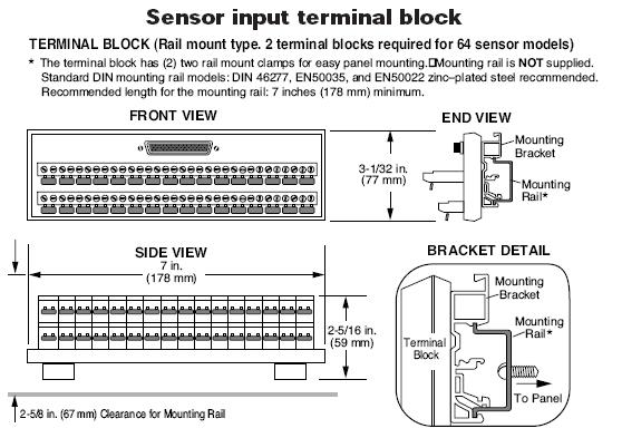
6 Control Relays The power supply has seven control relays to provide form C SPDT outputs for control functions of either the engine or electric motor application. Terminal Block Assembly Each sensor input terminal block consists of a 64-position, 32 pair input rail-mount terminal block for interface of panel or field-mounted end devices. For Class I Division 1 areas, end devices must be non-energy storing devices, such as mechanical switches with dry contacts. The terminal block is used for Normally Open sensors (one wire close to ground), and/or Normally Closed sensors (two wires). Ribbon Cable A 36 in. (914 mm) flat ribbon cable is required for connection of the S1501 head and the sensor input terminal block. The cable is supplied with two D-sub 37 PIN connectors at each end of the cable. Power and Control Cable The S1501 is connected to the power supply via the Power and Control Cable (15-conductor shielded cable, 72 in. [1.81 m] long). The cable is factory-sealed on the power supply end, and has a 15-pin, D-sub connector on the S1501 Head end. Sensor Inputs User-selectable Sensor Input types (Shutdown or Alarm Only) are available for each sensor. The sensor inputs are identified as follows: Class A: Inputs are operative (armed) all the time. Class B1: Inputs are enabled after the first preset Start-Run time period. Class B2: Inputs are enabled after the second preset Start-Run time period. Class C: Inputs are armed after the fault has been cleared for 2 seconds. Class P: Armed after the Load Relay has exergized and the process time has expired. Class ESD: Emergency Stop overrides the test lockout timer. Permissive Function This function was designed to monitor pre-lube pressure input. Terminal 32 of the sensor terminal block is reserved for a permissive pre-lube input. The pressure signal can be obtained from a pressure switch with normally open or normally closed contacts that indicates whether or not sufficient oil pressure has been reached during pre-lubing. If permissive pressure has not been reached, the system will not allow start-up. If the Permissive Function is not required, install a wire jumper in Terminal 32 and set the Permissive Timer setting at zero
7 Opto-Isolated Tach/Run Input The S1501 features an opto-isolated tach/run input located within the explosion-proof power supply. This special input is used for Run Input Sensing from a CD ignition, Magnetic Pickup, Motor Auxiliary Signal, or AC or DC run signals meeting the opto-isolated Tach/Run input specifications (refer to the Specifications section of this manual). NOTE: For tachometer sensing a magnetic pickup is recommended. Built-In Barrier (within the Power Supply) The S1501 power supply circuit is isolated from the Head by the intrinsically safe barrier located on the printed circuit board (power supply enclosure), between the power supply output and the power and control cable terminal block. A fuse barrier mounted inside the Power Supply isolates the power output to the Head. Zener diode shunt barriers isolate the seven control outputs from the Head. Hourmeter A hourmeter feature is available for the S1501 to record the engine or motor elapsed running time
 x 3-5/8 in. (92 mm). Insert the Head from the front side of the panel and install the two mounting clamps, one on each side of the case, (see mounting clamp detail).")
8 Installation WARNING: Perform the mounting operation with power source off. The S1501 Head was designed to be mounted within a weatherproof enclosure. It is intended for mounting in a flat panel. First, cut a square mounting hole of 3-5/8 in. (92 mm) x 3-5/8 in. (92 mm). Insert the Head from the front side of the panel and install the two mounting clamps, one on each side of the case, (see mounting clamp detail). Secure the unit to the panel by tightening the clamps with a blade type screwdriver. Mounting Dimensions
9
10 Typical Hazardous Areas Installation WARNING: FOR HAZARDOUS APPLICATION REQUIREMENTS, THE S1501 COMPLETE SYSTEM MUST BE INSTALLED IN ACCORDANCE WITH THE NATIONAL ELECTRICAL CODE (NEC) CLASS I, DIVISION 1, GROUP D (ARTICLE 504) SPECIFICATIONS. SENSOR INPUT WIRES MUST BE SEPARATED A MINIMUM OF 2 IN. (51 MM) FROM OTHER WIRES. USE OF SENSOR INPUT WIRE TYPE CONDUIT IS RECOMMENDED

11 S1501 System - Typical Hook Up Head Connections WARNING: PERFORM THE WIRING OPERATION WITH THE POWER SOURCE OFF AND THE AREA MADE NON-HAZARDOUS. MAKE SURE THE VOLTAGE AND CURRENT REQUIREMENTS ARE WITHIN THE S1501 SYSTEM RATINGS. CONDUIT IS REQUIRED TO PROTECT WIRES FROM DAMAGE. REFER TO THE SPECIFIC SYSTEM APPLICATION WIRING DIAGRAM SUPPLIED WITH YOUR UNIT. a. Interconnect the S1501 head and the power supply with the power and control cable, secure the connector in place by tightening the screws on each side of the connector. b. Repeat step (a.) for the RS232/RS485 serial port (if applicable). c. The sensor input connector(s) from the terminal block(s) plugs into the back of the Head. Secure by tightening the screws on each side of the connector
12 Typical Power Supply Connections WARNING: Do NOT route the power supply wiring and the sensor input lead wiring in the same conduit. a. Conduit installation: 1) Remove power before opening power supply cover. 2) Install one 1/2 in. NPT or two 3/4 in. NPT conduits, from customer end of the Power Supply. Note: Follow NEC guidelines for maximum number of wires in conduit. 3) Install an approved explosion-proof seal in the conduit within 18 in. (457 mm) of Power Supply enclosure (seal unused conduit holes). Important: Green screw above conduit hole (power supply) is to attach equipment ground per NEC. b. Customer Installed Field Wiring: Install wiring to power supply through conduit installed in step 2-a. 1) Run wiring from the power source to the S1501 power supply. 2) Connect the 120 VAC to the two AC Power Input terminals. Connect equipment ground to green screw (see schematic below). 3) Connect the 12 or 24 VDC Positive (+) lead to Power Input terminal DC. 4) Connect 12 or 24 VDC DC( ) lead to the GND terminal. (See Power Supply Typical Wiring Diagram.)
. Normally Closed Sensor Input Wiring Remove the factory-supplied jumper completely.")
13 Normally Open Sensor Input Wiring Wire each normally open sensor on top of the factory-supplied jumper. Loosen the screw and slide the wire lead into the terminal without removing the jumper (either side of jumper). Normally Closed Sensor Input Wiring Remove the factory-supplied jumper completely. Connect the two sides of the normally closed sensor to the two terminals of the terminal block. NOTE: Switches connected to the S1501 Sensor Input Terminal Block must be dry contact mechanical switches. Intrinsically Safe Barrier Wiring Important (normally open sensor only): Secure area of hazardous conditions before opening barrier cover or operating sensor contacts. a. Run Sensor switches wiring through conduit and isolate from the S1501 terminal block(s) with an explosion-proof barrier. b. For wiring refer to the following typical wiring diagrams
14 Normally Open System Barrier LCDT-ISB barrier (optional) Normally Closed System Barrier For normally closed non-intrinsically safe sensors, use an approved intrinsically safe barrier, and wire according to manufacturer s instructions
15 Power Supply Typical Wiring Diagram WARNING: Perform the wiring operation with the power source OFF and the area made non-hazardous. Make sure the voltage and current requirements are within the S1501 system ratings. Conduit is required to protect wires from damage. Refer to the specific system application wiring diagram supplied with your unit. NOTE 1: K-1 thru K-7 are relay outputs form C dry contacts. D1 thru D8 are LED indicators. D1= POWER ON; D2=K1; D3=K2; D4=K3; D5=K4; D6=K5; D7=K6; D8=K7. NOTE 2: Opto-isolated tach/run input jumper is shipped in the IGN position. IGN socket is used for negative or positive ground type CD ignitions. MPU socket is used for magnetic pickup or motor starter auxiliary contact not to exceed 120 Vrms
, and Sensor Setup.. YES - key used for scrolling up (increment). NO - key used for scrolling down (decrement). RESET - key used to reset alarms or shutdowns.")
16 Operation Operating the S1501 Interface Use the six membrane keys to scroll throughout the menus and to make changes to the System timers, Tachometer calibration, Overspeed, Underspeed, Run Hourmeter (ETM), and Sensor Setup.. YES - key used for scrolling up (increment). NO - key used for scrolling down (decrement). RESET - key used to reset alarms or shutdowns. MODE - key used for mode and test time modes. START/STOP key used for Local mode start and stop signals. ENTER - key used for entering/confirming set points and exiting menus
17 Sequence of Operations - Engine Mode ENGINE APPLICATION EVENT DISPLAY RELAY WAITING ON START Unit monitors for a valid start signal. Shutdown and Alarm relays are energized. * User can at this time, press the Mode key to modify desired setup tables. Class A inputs are scanned. Waiting On Start ETM: xxxxx.x hrs K1 K2 K3 K4 K5 K6 K7 Alar Lube Crank Ign. Fuel Load m SD Off Off Off Off Off On On Start signal received. Unit advances to Prelube cycle. Waiting On Start ETM: xxxxx.x hrs Off Off Off On Off On On If an RPM signal is seen before the Start signal is pressed, a fault occurs. PRELUBE CYCLE Prelube cycle begins. Permissive timer starts. Lube relay energized. Permissive time expires before Permissive signal* seen closed. Fault occurs. Lube relay is de-energized. Permissive signal closed. Prelube Cycle timer started. Prelube Cycle timer times down to zero. Unit advances to Crank cycle. CRANK CYCLE Crank Relay energizes. If the Run Delay Preset is > 0, the controller will wait for a Crank RPM permissive to proceed. If set to 0, this cycle is skipped Run Delay time expires before RPM > 10 is seen. Fault occurs. RPM > 10 is seen, or Crank Permissive cycle skipped. Cranking continues with purge timer started at preset time. Purge delay expires. Ignition relay is energized. Fuel On delay is started. Fuel On delay expires. Fuel relay energized. Crank timer started. The Controller will monitor for a Crank Disconnect RPM to advance to the Run Cycle. Crank timer expires before disconnect speed is reached. Unit goes into Rest cycle. Crank, Ignition, and Fuel relays are de-energized. When the Rest expires, the Crank Cycle will repeat. All crank attempts exhausted. Crank timer expires. Disconnect speed not reached. Overcrank condition occurs. All relays de-energized. Unexpected Engine Start! LUBE CYCLE... Permissive x:xx Permissive Failure LUBE CYCLE... Prelube x:xx LUBE CYCLE... Prelube :00 CRANK PERMISS... Run Delay x:xx Engine Failure Crank! To CRANK CYCLE... Purge :xx CRANK CYCLE... Fuel Delay :xx CRANK CYCLE... Crank :xx CRANK CYCLE... Rest :xx Overcrank Shutdown! Off Off Off On Off Off Off On Off Off Off Off On On Off Off Off Off Off Off Off On Off Off Off Off On On On Off Off Off Off On On On On Off Off Off On On Off Off Off Off Off Off Off On On Off Off Off On On On On On Off Off On On On On On On Off On On On Off Off Off Off On On Off Off Off Off Off Off Off
18 K1 K2 K3 K4 K5 K6 K7 RUN CYCLE Lube Crank Ign. Fuel Load ALM SD Crank Disconnect RPM reached. Crank relay deenergized. Class B1 Lockout, B2 Lockout and Load timers started. Class C shutdowns are allowed to arm. Class B1 and B2 Lockout timers expire. Elapsed time displayed. Unit monitors for stop condition. Load timer expires. Load relay energized. Process Lockout timer starts. When this timer expires, Class P shutdowns will be armed. User can press the Mode key to initiate the Test timer and test sensor inputs. IDLE CYCLE Stop signal is seen. Load relay is de-energized. Class P shutdowns are disarmed. Idle timer is started. ALARM FAULT Alarm only input faulted. Alarm relay de-energized. Fault alternately displayed with previous message displaying the speed and run hours. S1501 Reset key pressed. Alarm relay is picked up. Unit continues to scans for fault or stop condition. FAULT SHUTDOWN Unit receives a fault at sensor #4 for instance. The Fuel Valve, Alarm, and Shutdown relays are de-energized. Ignition ground delay expires. Ignition relay deenergized. Postlube cycle begins. Lube relay energized. Postlube expires. Lube relay de-energized. Fault is displayed. S1501 Mode key pressed. Shutdown type displayed. S1501 Reset key pressed. Unit waiting on start input. NORMAL STOP (AFTER IDLE CYCLE) Stop signal received and idle timer expired. Ignition ground delay begins. Fuel Valve relay de-energized. Ignition ground delay expires. Ignition relay deenergized. Postlube cycle begins. Lube relay energized. Postlube cycle timer expires. The Lube relay is deenergized. Unit returns to Waiting on Start. Speed: xxxxrpm Class-B1 x:xx Speed: xxxxrpm ETM: xxxxx.x hrs Speed: xxxxrpm Test Timer 5:00 Speed: Idle Low Coolant Level xxxxrpm x:xx Speed: xxxxrpm ETM: xxxxx.x hrs Speed: xxxxrpm Ign. Gnd. :xx LUBE CYCLE... Postlube x:xx Low Compressor Oil Pressure Sensor Input #04 Class B1,Shutdown Waiting On Start ETM: xxxxx.x hrs Speed: xxxxrpm Ign. Gnd. :xx LUBE CYCLE... Postlube x:xx Waiting On Start ETM: xxxxx.x hrs Off Off On On Off On On Off Off On On Off On On Off Off On On On On On Off Off On On Off On On Off Off On On On Off On Off Off On On On On On Off Off On Off Off Off Off On Off Off Off Off Off Off Off Off Off Off Off Off Off Off Off Off Off Off Off Off Off Off Off Off Off On On Off Off On Off Off On On On Off Off Off Off On On Off Off Off Off Off On On
19 Sequence of Operations Motor Mode ELECTRIC MOTOR APPLICATION EVENT DISPLAY RELAY WAITING ON START Unit monitors for a valid start signal. Shutdown and Alarm relays are energized. * User can at this time, press the Mode key to modify desired setup tables. Class A inputs are scanned. Waiting On Start ETM: xxxxx.x hrs K1 K2 K3 K4 K5 K6 K7 Not Lube Used Motor Cooler Load Alarm SD Off Off Off Off Off On On Start signal received. Unit advances to Prelube cycle. PRELUBE CYCLE Prelube cycle begins. Permissive timer starts. Lube relay energized. Permissive time expires before Permissive signal* seen closed. Fault occurs. Lube relay is de-energized. Permissive signal closed. Prelube Cycle timer started. Prelube Cycle timer times down to zero. Unit advances to Wait On Run cycle. WAIT ON RUN CYCLE Motor Relay energizes. Run delay and Cooler On Delays begin timing. The controller monitors for an electric motor auxiliary contact run confirmation. Run Signal not received before the delay expires, Fault occurs. All relays de-energize. S1501 Reset key pressed. Unit waiting on start input. RUN CYCLE Motor auxiliary contact seen closed. Lube relay deenergizes. Class B1 Lockout, B2 Lockout and Load timers started. Class C shutdowns are allowed to arm. Cooler On delay expires. The Cooler relay energizes. Class B1 and B2 Lockout timers expire. Elapsed time displayed. Unit monitors for stop condition. Load timer expires. Load relay energized. Process Lockout timer starts. When this timer expires, Class P shutdowns will be armed. User can press the Mode key to initiate the Test timer and test sensor inputs. IDLE CYCLE (COOLDOWN) Stop signal is seen. Load relay is de-energized. Class P shutdowns are disarmed. Idle timer is started. ALARM FAULT Alarm only input faulted. Alarm relay de-energized. Fault alternately displayed with previous message displaying the speed and run hours. S1501 Reset key pressed. Alarm relay is picked up. Unit continues to scans for fault or stop condition. Waiting On Start ETM: xxxxx.x hrs LUBE CYCLE... Permissive x:xx Permissive Failure LUBE CYCLE... Prelube x:xx LUBE CYCLE... Prelube :00 Waiting On Run Run Delay x:xx Motor Starter Failure! Waiting On Start ETM: xxxxx.x hrs Motor Running... Class-B1 x:xx Motor Running... Class-B1 x:xx Motor Running... ETM: xxxxx.x hrs Motor Running... Test Timer 5:00 Motor Running... Idle x:xx Low Coolant Level Motor Running... ETM: xxxxx.x hrs Off Off Off On Off On On On Off Off Off Off On On Off Off Off Off Off Off Off On Off Off Off Off On On On Off Off Off Off On On On Off On Off Off On On Off Off Off Off Off Off Off Off Off Off Off Off On On Off Off On On Off On On Off Off On On Off On On Off Off On On Off On On Off Off On On On On On Off Off On On Off On On Off Off On On On Off On Off Off On On On On On
20 FAULT SHUTDOWN Unit receives a fault at sensor #4 for instance. Motor, Cooler, Load, Alarm and Shutdown relays are deenergized. Postlube cycle begins. Lube Relay energized. Postlube expires. Lube relay de-energized. Fault is displayed. S1501 Mode key pressed. Shutdown type displayed. S1501 Reset key pressed. Unit waiting on start input. NORMAL STOP (AFTER IDLE-COOLDOWN CYCLE) Stop signal received and idle timer expired. Motor, and Cooler relays de-energized. Postlube cycle begins. Lube relay energized Postlube cycle timer expires. The Lube relay is deenergized. Unit returns to Waiting on Start. LUBE CYCLE... Postlube x:xx Low Compressor Oil Pressure Sensor Input #04 Class B1,Shutdown Waiting On Start ETM: xxxxx.x hrs LUBE CYCLE... Postlube x:xx Waiting On Start ETM: xxxxx.x hrs K1 K2 K3 K4 K5 K6 K7 Not Lube Used Motor Cooler Load Alarm SD On Off Off Off Off Off Off Off Off Off Off Off Off Off Off Off Off Off Off Off Off Off Off Off Off Off On On On Off Off Off Off On On Off Off Off Off Off On On
21 System Set Up Menus While the S1501 displays Waiting On Start, pressing the MODE key will access the SYSTEM SET UP menu. The following options are available: Timer Set Up Tach/Crank Set Up ETM Set Up Sensor Set Up Timer Set Up - This set up screen allows you to preset the system timers. Zeroing out a function s timer will bypass that particular function. Advanced Set Ups (password protected screens) The following Set Ups are available only under ADVANCED SETUP mode. Tach/Crank Set Up - This set up screen allows you to calibrate the internal tachometer with pulses per revolution and set the Overspeed, Underspeed, Crank Attempt set points, and Crank Disconnect. ETM Set Up - This set up screen allows you to preset the Elapsed Time Meter (ETM). Sensor Set Up - This set up screen allows you to edit shutdown or alarm messages and also to edit the input sensor class (A, B1, B2, C, P, or ESD) and the action (Alarm only or Shutdown). NOTE: Communications will be disabled while using the keypad to access the System Setup menu
22 Editing System Set Up Timer Set Up Menu There are a number of Timers that the S1501 system uses to carry out the start/stop sequencing. With all shutdowns cleared, and the S1501 at the Waiting On Start prompt, press the MODE key to gain access to the Timer Setup Menu. TIMER SETUP Permissive x:xx This displays the timer preset in MM:SS format. Press UP/YES or DOWN/NO keys to increase or decrease the time. Press RESET to zero the timer. Press ENTER to accept and save the setting and advance to the next timer. Repeat the procedure to preset all available timers. NOTE: To bypass a particular function, zero out the corresponding timer. For example, to bypass Prelube, zero out the Prelube timer. Permissive x:xx During the Prelube cycle, this is the preset time by which the Permissive input must be seen closed (NC system) or ungrounded (NO system). If the Permissive input is not satisfied, when the timer expires, a Permissive Failure fault shutdown will occur. NOTE: Terminal 32 is dedicated for the Permissive Pressure Input. To bypass this function, install a jumper at terminal 32. Prelube x:xx During the Prelube cycle, this is the preset time for which the Lube relay remains energized after the Permissive input is satisfied, prior to starting. Purge Delay x:xx Timer to purge excess fuel out of the engine on a crank attempt. The Crank relay is energized with the fuel valve relay de-energized and the ignition relay de-energized. Fuel Delay x:xx Timer to delay energizing the fuel valve relay on a crank attempt to burn unspent fuel. The ignition relay is energized during this time. Crank x:xx Time duration for the crank attempt after energizing the crank, ignition, and fuel valve relays. Rest x:xx Time duration for the Crank Rest period after the Crank period expires. However, if the specified number of Crank attempts is exhausted, an Overcrank Shutdown occurs. Run Delay x:xx
23 In Electric Motor applications (Pulses/rev = 0), this is the timer to gain the Motor Starter Auxiliary Run signal, after energizing the motor relay. If this signal is not seen before this timer expires, a Motor Starter Failure shutdown will occur. In Engine applications (Pulses/rev > 0), this is the timer to gain RPM reading > 10 before the Ignition and Fuel relays are energized. If this signal is not seen before this timer expires, an Engine Failure To Crank shutdown will occur. If set to 0, this RPM permissive is ignored. Class-B1 x:xx This timer locks out sensor inputs configured as Class B1 on startup. Class-B2 x:xx This timer locks out sensor inputs configured as Class B2 on startup. Load x:xx This timer delays energizing of the Load relay after starting, and is typically used as a warmup time. Process x:xx This timer locks out sensor inputs configured as class P after energizing the Load relay. This is typically used for Process alarms and shutdowns which do not clear until the unit has loaded. Idle x:xx This timer determines the length of time the system will run after de-energizing the Load relay after a stop signal is received. This is typically used for a Cooldown time period for the equipment. Ign. Gnd. x:xx In Engine applications (Pulses/rev > 0), this is the delay between de-energizing the fuel valve relay and de-energizing the ignition relay. This allows remaining fuel in the line to be burned off, prior to disabling the ignition system. Postlube x:xx After a stop or shutdown fault (non-esd) this is the time for which the Lube relay will be energized for a postlube cycle. Cooler Dly x:xx In Electric Motor applications ((Pulses/rev = 0), this timer delays energizing the cooler relay after energizing the motor relay to reduce inrush current imposed on the power source for the AC motors
24 Advanced Set Up Menu To calibrate the Tachometer and Elapsed Time Meter, select Crank attempts, Modbus RTU address, and modify sensor input information, a password protected setup mode is available. After the Timer Setup is complete, the LCD will read... ADVANCED SETUP Password XXXX To Exit Setup quickly without entering the Advanced Setup at this point, press RESET and ENTER at the same time. The first X will be blinking, to enter the password use the UP/YES or DOWN/NO keys to scroll through the characters. Press RESET and MODE to scroll between characters. When the correct password is entered, press ENTER to acknowledge. The following screen will be briefly displayed: ADVANCED SETUP PASSWORD OK! If password is incorrect the screen will be the following: ADVANCED SETUP PASSWORD ERROR! User will again be prompted to enter correct password. After 3 unsuccessful entries, the Advanced Set up is aborted and screen will return to Waiting On Start. ADVANCED SETUP Pulses/rev xx Press UP/YES or DOWN/NO keys to increase or decrease the value. Press ENTER to accept and save the setting and advance to the next setting. Pulses/rev xx To calibrate the internal tachometer, enter the pulses per revolution of the engine. To set the controller for an electric motor logic sequence, this setting must be set to 0. Enter either the number of teeth in the fly wheel if using a Magnetic Pickup, or use the following equation if using the Ignition input: Pulses = 2*Cylinders\Cycles For instance, for an 8 cylinder, 4 cycle engine, Pulses = 2*8\4 = 4 Attempts x Engine sequence only-this is the number of allowable engine crank cycles before an Overcrank Shutdown occurs. Disconnect xxxx Engine sequence only-this is the RPM at which the crank relay de-energized and the engine is considered running
25 Overspeed xxxx Engine sequence only-this is the excessive speed RPM at which the S1501 signals an internal Overspeed Shutdown. Underspeed xxxx Engine sequence only-this is the low speed RPM at which the S1501 signals an internal Underspeed Shutdown. This is not armed until the Class B1 timer expires. ETM 1k Hr xx Preset the Elapsed Time Hours thousands hours or use the RESET button to zero it. ETM 100 Hr xx Preset the Elapsed Time Hours hundred hours or use the RESET button to zero it. ETM Secs Hr xx Preset the Elapsed Time Hours seconds or use the RESET button to zero it
26 Sensor Set Up The S1501 system allows you to edit the Shutdown Message, Class Type and Shutdown Action (Shutdown Alarm or Alarm only) for each Sensor Input. Class Type are defined as follows: Class A, Shutdown Class B1, Shutdown Class B2, Shutdown Class C, Shutdown Class P, Shutdown ESD Shutdown Class A, Alarm Class B1, Alarm Class B2, Alarm Class C, Alarm Class P, Alarm Ignore Point Press UP/YES or DOWN/NO keys to select the input to modify. Select INPUT #0 to exit. Press ENTER once the desired input is chosen, and the corresponding shutdown message will be displayed. LOW OIL PRESSURE With the first character blinking you may change the character by pressing the UP/YES or DOWN/NO keys to scroll through available characters. Press MODE to move forward on character, or RESET to move backward. When the shutdown modification is completed, press ENTER to save the new message. The Sensor Class Type and function will now be displayed, for example: SHUTDOWN TYPE CLASS A SHUTDOWN To change the Class Type and function, use the UP/YES or DOWN/NO keys until the desired combination of Class and Function is reached. Press the ENTER key to save and return to the Setup screen. Repeat as above for all Sensors Inputs and Messages to be edited. Start/Stop Configuration The S1501 system can be configured for Local and/or Remote Start-Stop. Start-Stop is configured via terminal block inputs TB30 (local), TB31 (Remote). Keypad Start Jumper installed in TB30. A valid sequence occurs when the START/STOP key is pressed. Likewise, while running, a valid stop sequence occurs when the START/STOP key is pressed
27 NOTE: A valid stop occurs when the START/STOP key is pressed Regardless of the Start-Stop mode. Local-Off-Remote (L-O-R) Switch L-O-R switch installed across TB30 (Local) and TB31 (Remote). A valid sequence occurs when the L-O-R switch is placed in the Local position and the Start-Stop key is pressed OR the L-O-R is placed in the Remote position, and the Remote Start signal is seen. A valid Stop occurs when the L-O-R switch is placed in the OFF position, OR of in the Remote position and a Remote Stop is seen. Remote Start-Stop Jumper installed in TB31. A valid sequence occurs when a Remote Start signal is seen. Likewise, a valid stop occurs when the Remote Stop signal is seen. Maintain Start Jumper installed in TB31. A valid sequence occurs when the Maintain Start signal is seen. Likewise, a valid stop occurs when the Maintain Start signal is lost. Typical Start/Stop Wiring Modbus Start/Stop and Reset The S1501 system can be started and stopped remotely through the Modbus communications port (RS232/RS485 serial port). Writing a 1 to the start/stop register (40010) will initiate a start. Writing a Ø to the start /stop register will initiate a stop. Writing Ø to the shutdown status register (40004) will cause a reset
28 Modbus Integer Holding Registers Address Access Description Read RPM Read ETM (Elapsed Run Time Meter) Hundred Hours ( 0 999) Read Class B1 Timer Accumulator Seconds Read/ Write Shutdown Status Enumeration/Remote Modbus Reset (0=OK, or terminal block number of Shutdown event...writable to 0 for Modbus Reset) System Internal shutdowns: 68 = Engine Overspeed (engine applications) 70 = Engine Underspeed (engine applications) 72 = Overcrank (engine applications) 74 = Permissive Failure 76 = Motor Starter Failure (motor applications) 78 = Local Stop (by keypad) 80 = Unexpected Engine Start (engine applications) 86 = Loss of Tach Signal (engine applications) 88 = Loss of Run Signal (motor applications) 96 = Engine Failure To Crank (engine applications) Read Relay Output Status (bitmapped Bit 0=K1... Bit 1=K2, etc) Read Inputs TB01-16 Status (bitmapped Bit 0=TB1... Bit 1=TB2, etc) Read Inputs TB17-32 Status (bitmapped Bit 0=TB17... Bit 1=TB18, etc) Read Inputs TB33-48 Status (bitmapped Bit 0=TB33... Bit 1=TB34, etc) Read Inputs TB49-64 Status (bitmapped Bit 0=TB49... Bit 1=TB50, etc) Read/ Write Read/ Write Start/Stop Register (writable for remote commands if Remote Mode on TB29 is closed and remote maintained start digital input TB27 not used. It is active for a write of "0" at all times to allow remote stopping, until a start signal is received again) = Load/Unload Register (writable for resetting the Load relay after the LOAD relay has been energized by the program, and setting it again if it has been reset through Modbus. This resets and restarts the Process delay, at the same time as the Load relay is reset and set) Read ETM (Elapsed Run Time Meter) Thousand Hours ( 0 99 ) Read State Bitmap Bit 0 = WAITING ON START Bit 1 = PERMISSIVE Bit 2 = PRELUBE Bit 3 = CRANK PERMISSIVE Bit 4 = PURGE Bit 5 = FUEL DELAY Bit 6 = CRANK Bit 7 = REST Bit 8 = RUN DELAY Bit 9 = LOAD DELAY (WARMUP) Bit 10 = LOADED Bit 11 = UNLOADED Bit 12 = IDLE (COOLDOWN) Bit 13 = IGN GND DELAY Bit 14 = POSTLUBE Bit 15 = SHUTDOWN Read Alarm Status Enumeration (0=OK, or terminal block number of last alarm event)
29 Troubleshooting WARNING: Do NOT open power supply until operations have been shut down and area has been rendered non-hazardous. Do NOT run sensor wires in conduit with any other wire. Do NOT apply voltage to any annunciator input terminals. Do NOT bundle sensor wires with any other wiring. Make sure the voltage and current requirements are within the S1501 system ratings. Before going through the checklist below, refer to the connections and operation procedures. Also check your system wiring schematic. If any problems persist after you have made these checks, consult your nearest Murphy facility. Symptom: No display Check that the Power & Control cable is firmly connected to the back of the S1501. Check for damaged or broken wire. Check for power failure or power input shutdown. Check the 200 ma fuse within the S1501 power supply and replace if necessary. NOTE: If after all of the above has been done, and there is still no display, return the S1501 to Murphy for repair or replacement. Symptom: Engine fails to start (Sensor switch fault display cannot be cleared.) Check that the Power & Control cable is firmly connected to the back of the S1501. Check for damaged or broken wire. Check that the sensor input cable connector (ribbon cable) is properly connected to the back of the S1501. Verify that the LED lights (within the power supply box) are lit indicating relays are functioning. Check that the wire leads on the terminal block under the Safety Barrier cover are connected and tight. (See drawing at right.) Measure the voltage between terminals 1 and 2 on the terminal block under the Safety Barrier cover (voltage should read between 5-6 VDC). Do this with the S1501 connected to the power supply, and with it disconnected. There should not be more than a 0.5 V difference between the readings with the S1501 connected and not connected
30 Check sensor wires with an ohmmeter and meg or high potential test only with wires disconnected from sensor terminal block. NOTE: If shutdowns still result, contact your nearest Murphy representative/dealer
31 Specifications Power Consumption 120 VAC (7.5 VA) 12 VDC (3.5 watts) 24 VDC (3.5 watts) Sensor Inputs 32 or 64 N.O. and/or N.C. inputs such as Murphy Swichgage instruments. Field selectable as a Class A, B1, B2, C, P or ESD for shutdown, alarm, or control function. NOTE: Sensor inputs 27 through 32 reserved for control functions. Outputs 7-SPDT relay outputs, 5 A, 1/16 HP, 125/250 VAC/ 1 A, 30 VDC NOTE: For hazardous areas an approved isolation barrier must be used between sensor switch and input terminals if the sensor output comes from any energy storing device such as a relay or transistor. Adjustable Time Delays Permissive Prelube Purge Fuel Crank Run Class B1 Lockout Class B2 Lockout Process Lockout Idle/Cooldown Ignition Ground Postlube Cooler Sensor Inputs Terminal Block Rail mount DIN type; 32 terminals, screw type Opto-Isolated Tach/Run Input Magnetic pickup, 4.5 to 120 Vrms, 0-10 khz. CD ignition, positive or negative ground, 100 to 300 VDC, Hz. 12 to 125 VDC or 120 Vrms, 50/60 Hz may be used for run signals. Operating Temperatures: 32 to 122 F (0 to 50 C) Storage Temperatures: -4 to 158 F (-20 to 70 C) Case : ABS plastic, 1/4 DIN (90 x 90 mm) Communications Factory configured for RS232; field-selectable for RS485. Alphanumeric Display 2 lines, each line with 16 characters (32 characters total) Power Supply Enclosure Explosion-proof, Class I, Division 1. Intrinsically safe barrier built into the power supply, 120 VAC with 7 form C relay outputs for the following functions (with standard S1501): Lube Crank Ignition/Motor Fuel/Cooler Load Alarm Shutdown
32 Replacement Parts and Accessories To order the S1501 system specify the model number for each individual component and accessory: S1501H-32-2 S1501H-64-2 S1501CH-32-2 S1501CH-64-2 S1500TB32 S1500CA36 S1501PS-120 Accessories: S1501PCA72 S1501PS-120-E S1501PS-120-LC Head with RS232/RS485 port for 32 sensors Head with RS232/RS485 port for 64 sensors Head w/custom* program, RS232/RS485 port, 32 sensors Head w/custom* program, RS232/RS485 port, 64 sensors Terminal Block only** Ribbon Cable Assembly** 120 VAC, 12 or 24 VDC Power Supply Power and Control Cable Assembly, 72 in. (1.8 m) long Power Supply with 90 Conduit Elbow fitting Power Supply less case Approximate Shipping Weights / Dimensions S1501 complete system: 28 lb. (12.7 kg) / 20x14x12.5 in. (508x356x218mm) S1501H-32-2; S1501H-64-2; S1501CH-32-2; S1501CH-64-2: 2 lb. (0.907 kg) / 6x6x6 in. (152x152x152mm) S1500TB32: 2 lb. (0.907 kg) / 12x7x4 in. (305x178x102mm) S1500CA36; S1501PCA72: 2 lb. (0.907 kg) / 6x6x6 in. (152x152x152mm) S1501PS-120-LC: 3 lb. (1.36 kg) / 12x7x4 in. (305x178x102mm) S1501PS-120 and S1501PS-120-E: 22 lb. (9.98 kg) / 17x10x9.75 in. (431x254x248mm)
33
34 MURPHY and the Murphy logo are registered and/or common law trademarks of Murphy Industries, Inc. This document, including textual matter and illustrations, is copyright protected by Murphy Industries, Inc., with all rights reserved. (c) 2009 Murphy Industries, Inc. Other third party product or trade names referenced herein are the property of their respective owners and are used for identification purposes only

35
Series S1501 Selectronic Microcontroller/Annunciator. Installation and Operations Manual Section 50
 Series S1501 Selectronic Microcontroller/Annunciator Installation and Operations Manual 00-02-0819 2015-11-19 Section 50 Please read the following information before installing. BEFORE BEGINNING INSTALLATION
WARNING. TTDJ Series Fully-Configurable Fault Annunciator Installation and Operations Manual
 TTDJ Series Fully-Configurable Fault Annunciator Installation and Operations Manual TTDJ-99062N Revised 04-04 Section 50 (00-02-0412) Please read the following information before installing. This installation
EMS467 Monitoring System. Installation and Operations Manual Section 40
 EMS467 Monitoring System Installation and Operations Manual 00-02-0672 01-26-10 Section 40 In order to consistently bring you the highest quality, full featured products, we reserve the right to change
TTD Series Configurable Fault Annunciator. Installation and Operations Manual Section 50
 TTD Series Configurable Fault Annunciator Installation and Operations Manual 00-02-0697 2016-08-08 Section 50 In order to consistently bring you the highest quality, full-featured products, we reserve
TTD Series Configurable Fault Annunciator. Installation and Operations Manual Section 50
 TTD Series Configurable Fault Annunciator Installation and Operations Manual 00-02-0697 2013-04-22 Section 50 In order to consistently bring you the highest quality, full featured products, we reserve
MODBUS RTU I/O Expansion Modules - Models C267, C277, and C287. Installation and Operations Manual Section 50
 MODBUS RTU I/O Expansion Modules - Models C267, C277, and C287 Installation and Operations Manual 00-02-0651 09-01-09 Section 50 In order to consistently bring you the highest quality, full featured products,
MConfigPro Configuration Software. Installation and Operations Manual Section 50
 MConfigPro Configuration Software Installation and Operations Manual 00-02-0602 02-09-06 Section 50 In order to consistently bring you the highest quality, full featured products, we reserve the right
Quick Start Guide MC-III TM Flow Analyzer
 Quick Start Guide MC-III TM Flow Analyzer A Quick Reference on Mounting, Wiring, & Configuring the MC-III EXP or WP Flow Analyzer For complete instructions, see MC-III EXP User Manual, Part No. 9A-50165003
CENTURION Configurable Controller. Installation and Operations Manual Section 50
 CENTURION Configurable Controller Installation and Operations Manual 00-02-0590 10-10-06 Section 50 In order to consistently bring you the highest quality, full featured products, we reserve the right
SS2200 Remote Controller
 SS2200 Remote Controller General Purpose, DC Voltage General The SS2200 Remote Controller is a microprocessor-based programmable controller specifically designed to control single line and dual line centralized
INSTALLATION INSTRUCTIONS
 www.altroniccontrols.com INSTALLATION INSTRUCTIONS EXACTA 21 MONITORING AND CONTROL SYSTEM CAUTION: The EXACTA 21 CONTROL SYSTEM is CSA CERTIFIED FOR use in Class I, GROUPS C & D, Division 2 hazardous
PowerFlex 400 AC Drive Guide Specification
 PowerFlex 400 AC Drive Guide Specification Adjustable Frequency Drives with Bypass 3.0 50HP @ 208V AC 3.0 350HP @ 480V AC PART 1 GENERAL 1.01 Quality Assurance A. The manufacturer shall have minimum 5
MT400 MOTION CONTROLLER
 MT400 MOTION CONTROLLER INSTALLATION & TECHNICAL MANUAL 5/30/2012 417 Wards Corner Road Loveland, OH 45140 800.659.8250 FAX: 513.398.2536 www.maxitronic.com Table of Contents Page 3: Page 4: Page 5: Page
WARNING. EMS547 Engine Monitoring System. Installation and Operation Instructions Generic for All Versions. Sensor Inputs (See page 2 for details)
") EMS547 Engine Monitoring System Installation and Operation Instructions Generic for All Versions. GENERAL INFORMATION EMS-98140N Revised 06-03 Section 40 (00-02-0331) Please read the following instructions
EMS547 Engine Monitoring System Installation and Operation Instructions Generic for All Versions. GENERAL INFORMATION EMS-98140N Revised 06-03 Section 40 (00-02-0331) Please read the following instructions
Genset control and protection with safety system
 APPLICATION NOTES Generator Protection Unit, GPU-3 APPLICATION NOTES Genset control and protection with safety system Application description Functional description Wiring I/O lists Basic setup Flowcharts
PowerView Model PV1000. Hardware Installation Manual Section 78
 PowerView Model PV1000 Hardware Installation Manual 00-02-0599 07-19-07 Section 78 In order to consistently bring you the highest quality, full featured products, we reserve the right to change our specifications
Manual# Installation Manual SDU 410. Safety Shutdown Unit
 Manual# 1100641 Installation Manual SDU 410 Safety Shutdown Unit Installation Manual for SDU 410 ~~~ Safety Shutdown Unit Revision 1.0 Revised August 31, 2017 Revision history: Rev. Date Description 1.0
Quick Installation Guide
 Manual# 1100274 Quick Installation Guide SDU 410 Safety Unit Quick Installation Guide for SDU 410 Safety Unit ~~~ Revision 1.1 Revised November 10, 2016 Revision history: Rev. Date Description 1.0 04.2012
ETM MD100 Drive System 1/2HP (370W) User Manual. Table of Contents. Drive Features
 User Manual. Table of Contents. Drive Features") Table of Contents Drive Features... 1 Drive Specifications... 2 Certifications... 3 Installation - Drive Dimensions... 3 Motor Dimensions (mm)... 4 Drive Mounting... 4 Wiring... 5 I/O Terminals... 9 Menu...
Table of Contents Drive Features... 1 Drive Specifications... 2 Certifications... 3 Installation - Drive Dimensions... 3 Motor Dimensions (mm)... 4 Drive Mounting... 4 Wiring... 5 I/O Terminals... 9 Menu...
5450 NW 33rd Ave, Suite 104 Fort Lauderdale, FL Fruitland Ave Los Angeles, CA SST7000 SST7100. Speed Switch / Transmitter
 5450 NW 33rd Ave, Suite 104 Fort Lauderdale, FL 33309 3211 Fruitland Ave Los Angeles, CA 90058 SST7000 SST7100 Speed Switch / Transmitter Installation and Operation Manual Rev. C P/N145F-13112 PCO 00009270
MYRIAD QLC 4-CHANNEL MONITOR/CONTROLLER INSTRUCTION MANUAL
 MYRIAD QLC 4-CHANNEL MONITOR/CONTROLLER INSTRUCTION MANUAL VISIT OUR WEBSITE SIGMACONTROLS.COM MYR QLC MANUAL 013114 2 TABLE OF CONTENTS INTRODUCTION 3 Ordering Information Specifications Features WIRING
Genset Controller Unit Model EMS - GC10. Installation Manual Section
 Genset Controller Unit Model EMS - GC10 Installation Manual 00-02-0794 Section 75 2013-01-28 In order to consistently bring you the highest quality, full featured products, we reserve the right to change
CENTURION Configurable Controller. Installation and Operations Manual Section 50
 CENTURION Configurable Controller Installation and Operations Manual 00-02-0590 02-09-06 Section 50 In order to consistently bring you the highest quality, full featured products, we reserve the right
ALTERNATING RELAYS & CONTROLLERS ARM Series
 ALTERNATING RELAYS & CONTROLLERS ARM Series Process Control Equipment for Hazardous Locations 7M26 UL913 INCLUDES INTRINSICALLY SAFE INPUTS Integrated Duplex Controller SOSO Operation (Sequence-on, Simultaneous-off)
Manual# Installation Manual. 200E Series. DCU 210E/208E Engine Panel RP 210E/220E Remote Panel
 Manual# 1006495 Installation Manual 200E Series DCU 210E/208E Engine Panel RP 210E/220E Remote Panel Installation Manual for the Marine Pro 200E Series ~~~ DCU 210E/208E Diesel Engine Control Unit RP 210E/220E
TraceTek Leak Detection Master Module Installation Instructions TOOLS REQUIRED STORAGE
 TTDM-128 TraceTek Leak Detection Master Module Installation Instructions TRACETEK APPROVALS AND CERTIFICATIONS TYPE NM General Signaling Equipment 76LJ GENERAL INFORMATION Please read these instructions
DATA SHEET Compact Genset Controller, CGC 200
 DATA SHEET Compact Genset Controller, CGC 200 Auto start and parameter monitoring Warnings and shutdown protections Includes 5 digital inputs, 5 relay outputs Configurable for other applications Licence-free
PowerCore Model TEC-10 Installation Manual
 PowerCore Model TEC-10 Installation Manual Products covered in this document comply with European Council electromagnetic compatibility directive 2014/30/EU and electrical safety directive 2014/35/EU.
CENTURION - C4 Series Configurable Controller. Installation and Operations Manual Section 50
 CENTURION - C4 Series Configurable Controller Installation and Operations Manual 00-02-0696 2017-12-12 Section 50 FW Murphy has made efforts to ensure the reliability of the Centurion controller and to
Quick Start Installation Guide
 apc/l Quick Start Installation Guide Version A2 Document Part Number UM-201 May 2010 OVERVIEW The apc/l is an intelligent access control and alarm monitoring control panel which serves as a basic building
5450 NW 33rd Ave, Suite 104 Fort Lauderdale, FL Fruitland Ave Los Angeles, CA UM Channel Monitor.
 5450 NW 33rd Ave, Suite 104 Fort Lauderdale, FL 33309 3211 Fruitland Ave Los Angeles, CA 90058 UM-600 6-Channel Monitor Version 2 Installation and Operation Manual Rev. G P/N145F-12990 PCO 00007462 (c)
Operating Instructions
 Operating Instructions DE-3000 Series Configurable Safety Shutdown and Control System with Graphing Capabilities Form SOME FEATURES IN THIS MANUAL ARE ONLY APPLICABLE TO DE-3000 FIRMWARE DATED 2014 OR
Operating instructions. Speed monitor D / / 2014
 Operating instructions Speed monitor D200 80005257 / 00 05 / 2014 Contents 1 Preliminary note...4 1.1 Symbols used...4 1.2 Warning signs used...4 2 Safety instructions...5 2.1 General...5 2.2 Target group...5
Your Global Flow Control Partner. Series 50 Valve Status Monitor Operation and Maintenance Manual
 Your Global Flow Control Partner Series 50 Valve Status Monitor Table of Contents 1. Definition of Terms... 2 2. Safety... 2 3. Storage... 3 4. Commissioning... 3 4.1. Mounting your VSM... 3 4.2. Wiring
Scanner 2000 microefm QuickStart. Installing the Scanner Remote Mount. Direct Mount NUFLO. Part No , Rev. A
 NUFLO Part No. 30165024, Rev. A Scanner 2000 microefm QuickStart Installing the Scanner 2000 H L H L Flow Direct Mount To install the Scanner 2000 microefm using a direct mount to an orifice or cone meter
Quantum III. Compact DC Drive Package. Slitter DC Drive Package. Quantum III
 Compact DC Drive Package The delivers a DC drive package that integrates the intelligence of the Mentor II with a space saving design that incorporates many accessories typically required in the North
Level-Lance Model 5400A
 Sales Manual Section 100 PRODUCT SPECIFICATION 5400A GENERAL DESCRIPTION The ROBERTSHAW Level-Lance Model 5400A is a microprocessor based, multi-point On-Off capacitance type level detection system. Utilizing
TURCK Process Automation IS Interface Technology. Interface Modules. IM Series Cabinet
 Process Automation IS Interface Technology Interface Modules TURCK's IM series of Isolating Intrinsically Safe Barriers is designed to be a simple and safe way to solve the problems associated with the
Panel Indicators. NEW 4~20mA Panel Display. Process Indicators INTECH INSTRUMENTS.
 The LPI-LCD-6-4~20mA panel display is ideal for displaying a variety of process variables, and is easy to scale to your required engineering units. LPI-LCD-6 4~20mA Panel Display. Loop powered. Loop powered
INSTALLATION DKM-409 NETWORK ANALYSER WITH HARMONIC MEASUREMENT AND SCOPEMETER. Before installation:
 DKM-409 NETWORK ANALYSER WITH HARMONIC MEASUREMENT AND SCOPEMETER The DKM-409 is a precision instrument designed for displaying various AC parameters in 3-phase distribution panels. Thanks to its isolated
Manual Control Unit GFC 32
 Manual Control Unit 1400004_EN/05.2017 Index 1. Main features 3 2. Technical features 3 3. Installation guidelines 4 4. Preliminary checks 5 5. Electrical connections 5 6. Settings 6 7. Remote control
TT /12b INSTALLATION INSTRUCTIONS. Introduction
 TT-1545 11/12b INSTALLATION INSTRUCTIONS Original Issue Date: 6/10 Model: 20-300 kw Generator Sets Market: Industrial Subject: Decision-Maker 3000 Controller Service Replacement Kit GM75376 Introduction
700 SERIES DPC DUPLEX PUMP CONTROLLER INSTRUCTION MANUAL
 1 700 SERIES DPC DUPLEX PUMP CONTROLLER INSTRUCTION MANUAL VISIT OUR WEBSITE SIGMACONTROLS.COM 700 DPC MANUAL 072114 2 TABLE OF CONTENTS INTRODUCTION 3 Ordering Information Specifications Features WIRING
FLEX Ex Spring Clamp Terminal Base
 Installation Instructions FLEX Ex Spring Clamp Terminal Base (Cat. No. 1797-TB3S) 1 10 11 4 Only remove this cover plug if connecting another terminal base unit. 3 5 6 12 2 7 8 9 41253 Component Identification
KBMG MULTI-SPEED BOARD
 TM INSTALLATION AND OPERATION MANUAL KBMG MULTI-SPEED BOARD KB Part No. 8833 Multi-Speed Board for KBMG Series Regenerative Drive Pending! See Safety Warning on Page 1 The information contained in this
M2500 Engine Controller Configuration Manual
 M2500 Engine Controller Configuration Manual Revision: 08-04-2011 Page 1 Contents 1 Preface... 4 2 Configuration from front panel... 5 2.1 Engine Controller Configuration... 6 2.1.1 RPM settings... 6 2.1.2
MAXIMA + Series ROTARY LEVEL CONTROL
 Price $5.00 MAXIMA + Series ROTARY LEVEL CONTROL OPERATING INSTRUCTIONS PLEASE READ CAREFULLY Division of Garner Industries 7201 North 98th Street Lincoln, NE 68507-9741 (402) 434-9102 925-0268 TABLE OF
Differential Liquid/Gas Pressure Transmitter
 Installation Instruction Differential Liquid/Gas Pressure Transmitter Catalog Number(s) 1414-CPZ10FWFAA, 1414-IPZ10FWFAA Explosion Hazard WARNING Do not use in an explosive or hazardous environment, with
TABLE OF CONTENTS INTRODUCTION. 3. Analog Input Analog Output Digital Input Digital Output OPERATIONAL DESCRIPITON.. 7 PROGRAMMING AND INITIAL SETUP.
 DIVERSIFIED HEAT TRANSFER SERIES 700 STEAM GENERATOR CONTROLLER INSTRUCTION MANUAL VISIT OUR WEBSITE AT SIGMACONTROLS.COM SERIES 700 DHT STEAM GENERATOR MANUAL 042514 2 TABLE OF CONTENTS INTRODUCTION.
This document set is applicable to the following part number configurations:
 This document set is applicable to the following part number configurations: Part Number Kit Configuration Instrument Sensors VA200 VA200 - VA200K VA200 1 X A200-HAS Voltmeter and ammeter systems VA200X
APPLICATION GUIDE. Interface Modules IM Series.
 Interface Modules IM Series APPLICATION GUIDE www.turck.com Interface Technology Interface Modules TURCK's IM series of Isolating Intrinsically Safe Barriers is designed to be a simple and safe way to
PowerView. Model PV-101-A, V2.3 User s Guide Section 78
 PowerView Model PV-101-A, V2.3 User s Guide 10-18-11 00-02-0795 Section 78 In order to consistently bring you the highest quality, full featured products, we reserve the right to change our specifications
PowerView. Model PV-101 User s Guide. Rev Catalog Section 78
 PowerView Model PV-101 User s Guide Rev 09-10-08 00-02-0605 Catalog Section 78 In order to consistently bring you the highest quality, full featured products, we reserve the right to change our specifications
Programming and Installation Manual
 Flow Meters 100 East Felix St. South, Suite 190 Fort Worth, Texas 76115 800.235.1638 Fax: 817.921.52822 www.blancett.com Specifications Power Supply: - 1 D size 1.5 Volt Alkaline Battery - 4-20mA Loop
Table of Contents 1. Overview Installation...6
 (2003-01-31) Table of Contents 1. Overview...1 1.1. Introduction... 1 1.2. Product Description... 1 1.2.1. Mechanical Actuator Assembly with M2CP Electrical Enclosure... 1 1.2.2. Variable Frequency Controller
This document set is applicable to the following part number configurations:
 This document set is applicable to the following part number configurations: Part Number Kit Configuration Instrument Sensor TM202 TM202 - TM202B TM202 1 X A200-HMB TM202S TM202 1 X A200-HMS TM202R TM202
Installation & Operation Guide
 Installation & Operation Guide (Shown with optional Override Board Cover) KMD-5831 Programmable Loop Controller PLC-28 Direct Digital Controller 902-019-04B 1 Introduction This section provides a brief
MAXIMA + Series ROTARY LEVEL CONTROL
 Price $5.00 MAXIMA + Series ROTARY LEVEL CONTROL OPERATING INSTRUCTIONS PLEASE READ CAREFULLY Division of Garner Industries 7201 North 98th Street Lincoln, NE 68507-9741 (402) 434-9102 925-0268 Rev. A
INSTRUCTION MANUAL STATION CONTROLLER SC1000 MOTOR PROTECTION ELECTRONICS, INC.
 INSTRUCTION MANUAL STATION CONTROLLER SC1000 MOTOR PROTECTION ELECTRONICS, INC. 2464 Vulcan Road, Apopka, Florida 32703 Phone: (407) 299-3825 Fax: (407) 294-9435 Revision Date: 9-11-08 Applications: Simplex,
SLATE. Digital I/O Module INSTALLATION INSTRUCTIONS R8001D4001
 SLATE Digital I/O Module R8001D4001 INSTALLATION INSTRUCTIONS Scan for more information Application SLATE brings configurable safety and programmable logic together into one single platform. The platform
6-Channel Monitor. Installation and Operation Manual
 3211 Fruitland Ave Los Angeles, CA 90058 Catalyst Monitor 6-Channel Monitor Version 2 Installation and Operation Manual Rev. H P/N145F-12964 PCO - 00009743 (c) Copyright 2015, Barksdale, Inc. All Rights
MODEL SW6000 & SM6100 CENELEC INSTRUCTIONS
 MODEL SW6000 & SM6100 CENELEC INSTRUCTIONS Installation Manual 1180 METRIX Experience Value 8824 Fallbrook Dr. Houston, TX 77064, USA Tel: 1-281-940-1802 After Hours Technical Assistance: 1-713-702-8805
MAXIMA+ Series Rotary Level Indicator
 MAXIMA+ Series Rotary Level Indicator BinMaster: Division of Garner Industries 7201 N. 98th St., Lincoln, NE 68507 402-434-9102 email: info@binmaster.com www.binmaster.com OPERATING INSTRUCTIONS PLEASE
AirTest Model CN9000 Series Sensor Controller
 AirTest Model CN9000 Series Sensor Controller AirTest Model CN9000 Series Sensor Controller THEORY OF OPERATION A basic CN9000 configuration consists of Input/Process/Display combination modules, a 3 relay
Sidewinder Pumps Inc. AC C1D2 Timer/Controller
 Sidewinder Pumps Inc. AC C1D2 Timer/Controller Page 1 of 14 Rev 4/26/17 Table of Contents 1. Warnings --------------------------------------------------------------------------------------------------
DMC2. Installation Guide Version 1.0. Area for main photograph. Area for insert photo. W: 46.1mm up to 79 mm H: 46.1mm
 Area for main photograph Area for insert photo W: 46.1mm up to 79 mm H: 46.1mm X: 12.6mm absolute on page Y: 132.6mm abs on page This insert has a shadow DMC2 Installation Guide Version 1.0 Contents DMC2
Installing Your 1394 Drive Interface Module
 Installation Instructions Installing Your Drive Interface Module (Catalog Number -DIM) Introduction This publication provides installation instructions for adding the Drive Interface Module to your system.
DSEULTRA DSE3110 Series Control Module
 DSEULTRA DSE3110 Series Control Module 057-086 Author : Anthony Manton DSE Model 3000 Series Control and Instrumentation System Operators Manual Deep Sea Electronics Plc Highfield House Hunmanby North
G540 User Manual. Date Modified: March 5, 2012 Page 1 of 10
 G540 User Manual Date Modified: March 5, 2012 Page 1 of 10 DIMENSIONS PHYSICAL AND ELECTRICAL RATINGS Minimum Maximum Units Supply Voltage 18 50 VDC Motor Current 0 3.5 A Power Dissipation 1 13 W Short
2 Table of Contents 1. TABLE OF CONTENTS. 1. Table of Contents Introduction Wiring Diagram Terminals Review...
 TPR-6 Temperature Protection Relay Instruction Manual Ver. June 1 st 2010 2 Table of Contents 1. TABLE OF CONTENTS 1. Table of Contents... 2 2. Introduction... 3 3. Wiring Diagram... 5 4. Terminals Review...
EnerSure Installation Guide
 EnerSure Installation Guide Danger!!! The electrical components of this system may contain voltage and /or amperage sufficient to injure or kill. Installation is only to be performed by a licensed, bonded
SED2 Variable Frequency Drives with Electronic (E) Bypass Options
 Bypass Options") SED2 Variable Frequency Drives with Electronic (E) Options Description The E- Options are companion packages for the family of SED2 Variable Frequency Drives (s). For information on the family of SED2
SED2 Variable Frequency Drives with Electronic (E) Options Description The E- Options are companion packages for the family of SED2 Variable Frequency Drives (s). For information on the family of SED2
G540 MANUAL MULTIAXIS STEP MOTOR DRIVE
 G540 MANUAL MULTIAXIS STEP MOTOR DRIVE PRODUCT DIMENSIONS PHYSICAL AND ELECTRICAL RATINGS Minimum Maximum Units Supply Voltage 18 50 VDC Motor Current 0 3.5 A Power Dissipation 1 13 W Short Circuit Trip
700 SERIES TPC TRIPLEX PUMP CONTROLLER INSTRUCTION MANUAL
 1 700 SERIES TPC TRIPLEX PUMP CONTROLLER INSTRUCTION MANUAL VISIT OUR WEBSITE SIGMACONTROLS.COM 700SERIESTPCMANUAL071414 2 TABLE OF CONTENTS INTRODUCTION 3 Ordering Information Specifications Features
CONTROL MICROSYSTEMS and 5407 Relay Output Module. Hardware Manual
 506 and 507 Relay Output Module Hardware Manual CONTROL MICROSYSTEMS SCADA products... for the distance Steacie Drive Telephone: 63-59-93 Kanata, Ontario Facsimile: 63-59-0 KK A9 Technical Support: -6-676
DGC-2000 DIGITAL GENSET CONTROLLER
 DGC-2000 DIGITAL GENSET CONTROLLER Basler Electric s Digital Genset Controller (DGC-2000) offers an integrated alternative for genset control and monitoring. Control includes engine starting and shutdown
Manual# Installation Manual. 400E Series. DCU 410E Engine Control Unit RP 410E Remote Panel
 Manual# 1100346 Installation Manual 400E Series DCU 410E Engine Control Unit RP 410E Remote Panel RP 410E DCU 410E Installation Manual for Marine Pro 400E Series ~~~ DCU 410E Engine Control Unit RP 410E
D115 The Fast Optimal Servo Amplifier For Brush, Brushless, Voice Coil Servo Motors
 D115 The Fast Optimal Servo Amplifier For Brush, Brushless, Voice Coil Servo Motors Ron Boe 5/15/2014 This user guide details the servo drives capabilities and physical interfaces. Users will be able to
MRC 7000 Proven Recording Reliability that Became the Industry Standard!
 Data Sheet Recorder//Profiler DESCRIPTION The MRC7000 Recorder/ is a microprocessor based circular chart instrument capable of measuring, displaying, recording and controlling up to two process variables
R & D SPECIALTIES SERIES 100 RO CONTROLLER USERS MANUAL. 2004, by R & D Specialties, Inc. All Rights Reserved.
 R & D SPECIALTIES 2004, by R & D Specialties, Inc. All Rights Reserved. No part of this document may be copied or reproduced in any form or by any means without the prior written permission of R & D Specialties.
Digital Speed Controller User Manual
 Diesel Engine for Generators Digital Speed Controller User Manual (DSC-1000) Ver_1.0 Doosan Infracore 페이지 1 / 36 Contents 1. Product Overview and General Specification 1.1 Product Information 1.2 Product
Manual Simatek Control Unit GFC 32
 Manual Simatek Control Unit GFC 32 Original instructions 1400004_GB Ver. 2014.01.09 Index 1. Main features 3 2. Technical features 3 3. Installation guidelines 4 4. Preliminary checks 5 5. Electrical connections
INTRINSICALLY SAFE DUPLEXER PROTECTION. ELECTRONICS, INC Vulcan Road Apopka, Florida MOTOR INSTRUCTION MANUAL
 INTRINSICALLY SAFE DUPLEXER INSTRUCTION MANUAL MOTOR PROTECTION ELECTRONICS, INC. 2464 Vulcan Road Apopka, Florida 32703 Phone: Website: (407) 299-3825 www.mpelectronics.com Operating Program Revision:
SMARTSTART MOTOR STARTERS
 SMARTSTART MOTOR STARTERS MCG WWW.MCG-USA.COM 1 AT A GLANCE Covers all line voltages from 200-600V AC, single or three phase Transformer supplies a 24V AC coil voltage, no matter the line voltage 12V AC/DC
This document set is applicable to the following part number configurations:
 This document set is applicable to the following part number configurations: Part Number Kit Configuration Instrument Sensors VA200 VA200 - VA200K VA200 1 X A200-HAS Voltmeter and ammeter systems VA200X
InteliLite MRS17 Click Here to Learn More
 InteliLite MRS17 Click Here to Learn More Comprehensive Genset Controller Brief Description The InteliLite is a cost effective controller for generator sets in stand-by and prime power applications. The
*Approved by CSA for non-hazardous locations (Group Safety Publication IEC Third Edition).
.") PowerCore Model MPC-20 Installation Manual *Approved by CSA for non-hazardous locations (Group Safety Publication IEC 61010-1 Third Edition). Products covered in this document comply with European Council
PowerCore Model MPC-20 Installation Manual *Approved by CSA for non-hazardous locations (Group Safety Publication IEC 61010-1 Third Edition). Products covered in this document comply with European Council
BA/BS4S Temperature Sensor Installation & Operating Instructions
 Product Overview and Identification The BAPI-Stat 4 room temperature sensor features a large format LCD and slider setpoint adjustment. Additional options include button override and communication jack.
Dual Channel Monitor for Measurement of Speed and Ratio with SIL1 requirements Series D224.xx
 D224 Dual Channel Monitor for Measurement of Speed and Ratio with SIL1 requirements Series D224.xx D224 Front View KEY FEATURES SIL1 / IEC 61508:2010 compliant Dual Channel Speed and Ratio Monitor with
PGR-6101 MANUAL GROUND-FAULT & INSULATION MONITOR
 Tel: +1-800-832-3873 E-mail: techline@littelfuse.com www.littelfuse.com PGR-6101 MANUAL GROUND-FAULT & INSULATION MONITOR Revision 0-C-041918 Copyright 2018 by Littelfuse, Inc. All rights reserved. Document
ICS Regent. Relay Output Modules. Low Power and High Power (T3446L and T3446H) PD-6017
 PD-6017") ICS Regent PD-6017 Relay Output Modules Low Power and High Power (T3446L and T3446H) Issue 1, March, 06 Relay output modules provide control of eight user output loads. Two types of relay output modules
ICS Regent PD-6017 Relay Output Modules Low Power and High Power (T3446L and T3446H) Issue 1, March, 06 Relay output modules provide control of eight user output loads. Two types of relay output modules
SIAC-PS 3G SIGNAL ISOLATOR WITH POWER SUPPLY (PART NO. 8890) INSTALLATION INSTRUCTIONS
 INSTALLATION INSTRUCTIONS") SEE SAFETY WARNING ON PAGE 6 SIAC-PS 3G SIGNAL ISOLATOR WITH POWER SUPPLY IS DESIGNED TO BE USED WITH KBAC 3G SERIES DRIVES ONLY KBAC 3G SERIES MODELS CONTAIN THE "(3G)" DESIGNATOR ON THE PRODUCT LABEL
SEE SAFETY WARNING ON PAGE 6 SIAC-PS 3G SIGNAL ISOLATOR WITH POWER SUPPLY IS DESIGNED TO BE USED WITH KBAC 3G SERIES DRIVES ONLY KBAC 3G SERIES MODELS CONTAIN THE "(3G)" DESIGNATOR ON THE PRODUCT LABEL
Compact Genset Controller, CGC 200 Mounting Terminals and wiring Commissioning, using the Utility Software and/or the front panel
 INSTALLATION AND COMMISSIONING INSTRUCTIONS Compact Genset Controller, CGC 200 Mounting Terminals and wiring, using the Utility Software and/or the front panel DEIF A/S Frisenborgvej 33 DK-7800 Skive Tel.:
CDD Carbon Dioxide Transmitter
 Introduction The OSA CO2 transmitter uses Infrared Technology to monitor CO2 levels within a range of 0 2000 ppm and outputs a linear 4-20 ma or 0-5/0-10 Vdc signal. The enclosure is designed to operate
Vibration Switches viib
 Vibration Switches technivib -- Z.I de Pringy -- 531 route des vernes 74 370 PRINGY France Tél :: 0033 4 50 01 23 20. Fax :: 0033 4 50 01 57 81 e.mail :: info@technivib.com Website : : www.technivib.com
Flow Meters. Model B Flow Monitor. Model B2800. Flow Monitor
 Flow Monitor Model B2800 Flow Meters Model B2800 Flow Monitor Microprocessor-based flow monitor and totalizer Use with Blancett turbine flow meters as well as other flow meters with a frequency output
Ratio Feeder Series J+ Advanced Pumper Controller
 UNPACKING Figure 1 J Plus Controller Please open and inspect your package upon receipt. Your package was packed with great care and all the necessary packing materials to arrive to you undamaged. If you
ESC 201. Installation and Operating Instructions Manual. SG Jan 2015
 ESC 201 Installation and Operating Instructions Manual SG-0002-03 Jan 2015 Table of Contents 1.0 FUNCTIONS... 5 2.0 FEATURES... 5 3.0 ESC 201 DESCRIPTION... 6 4.0 GENERAL OPERATIONS... 6 4.1 MANUAL MODE
Centurion C5 M-VIEW Monochrome LCD (MV-5-C) Operations Manual Section 50
 Operations Manual Section 50") Centurion C5 M-VIEW Monochrome LCD (MV-5-C) Operations Manual 00-02-1031 2019-02-14 Section 50 BEFORE BEGINNING INSTALLATION OF THIS FW MURPHY PRODUCT: Please read the following information before operating
Centurion C5 M-VIEW Monochrome LCD (MV-5-C) Operations Manual 00-02-1031 2019-02-14 Section 50 BEFORE BEGINNING INSTALLATION OF THIS FW MURPHY PRODUCT: Please read the following information before operating
DE SERIES. Enhanced DE-2500 System Now Available. Programmable Safety Shutdown, Monitoring and Control Products with Analog Input Capabilities
 Enhanced DE-2500 System Now Available DE SERIES Programmable Safety Shutdown, Monitoring and Control Products with Analog Input Capabilities A state-of-the-art family of products specifically designed