AndyMark Arduino Tutorial
|
|
|
- Pierce Horton
- 6 years ago
- Views:
Transcription
 - Logitech Gamepad F310 (am-2064) - MK ES17-12, 12 Volt, 17 Amp-Hour Sealed Lead Acid Battery (half of am-0844) - Battery Cable (am-0009) -")
1 AndyMark Arduino Tutorial Tank Drive June 2014 Required: Required Software List: - Kit Arduino IDE - Robot Power Cable Kit (am-0975) RobotOpen Arduino Shield Software - Battery Base Package (am-0477) RobotOpen Driver Station - D-Link DAP-1522 Radio (am-0839) - Logitech Gamepad F310 (am-2064) - MK ES17-12, 12 Volt, 17 Amp-Hour Sealed Lead Acid Battery (half of am-0844) - Battery Cable (am-0009) - Ethernet Arduino and Peasy Breakout Board Combo (am-2734) - Or an Arduino with a Breadboard and 13 Jumpers - Programmer Cable (am-2416) Amp Snap Action Breakers (am-0290) - Ethernet Cable (am-0499) - Assembled Robot - Windows XP OR Newer 1
2 Table of Contents Section Page # Setting Up the Software 3 Wiring the Arduino 4-6 Programing the Robot 7-10 Configuring the Driver Station 11 Connecting the Robot and Driver Station 12 Troubleshooting Appendix A: PWM Appendix B: The Driver Station 18 Appendix C: Motor Bias


3 Setting Up the Software Arduino IDE : Once you have downloaded Arduino IDE Double Click on Arduino You may need to right-click and select Run as Administrator Install to a known location. Setting up the RobotOpen Software Once you have downloaded RobotOpen Arduino Shield Software: Open the RobotOpen-Shield-Library-master zip file Find and right-click on the RobotOpen file folder Select copy Open the Arduino folder The default location for this file is in your Program Files My filepath was: C:\Program Files (x86)\arduino Paste the RobotOpen folder into the Libraries folder Wiring the Arduino 3
 Plug in your USB-to-FTDI Cable (am-2416) into an open USB Port on your computer Rotate the Arduino so the FTDI Port is facing your computer Plug the other end of the")

4 Place your Arduino on a desk so it doesn t short out. FTDI Port (Programming Port) Plug in your USB-to-FTDI Cable (am-2416) into an open USB Port on your computer Rotate the Arduino so the FTDI Port is facing your computer Plug the other end of the cable into your Arduino s FTDI Port Ethernet Port Plug one end of your ethernet cable (am-0499) into the ethernet port on your computer Plug the other end of your ethernet cable into the Arduino s Ethernet Port Note: If your computer does not have a ethernet port you will need to read the tutorial on the Arduino Wireless. Note: You now will need to place your robot on blocks, so that it s wheel are off the ground. Place your Arduino on the robot while keeping everything plugged into the computer The Peasy Board (am-2734) plugs directly into the Arduino like so: Once plugged into the Peasy Board: Plug PWM wires from the speed controller into the peasy board using the following configuration: 4

5 Front Left = Digital Pin 9 Rear Left = Digital Pin 3 Front Right = Digital Pin 6 Rear Left = Digital Pin 5 The yellow wire should insert into the headers that are labeled sig. Note: Make sure all of your speed controllers are off. Alternatively : You can use a breadboard. This will be less convenient than the Peasy Board, but it will still work. To match our example programs, you may want to wire the Arduino to the breadboard this way: 5
6 Programming the Arduino The Program Open up the Arduino IDE You may need to right-click and select run as administrator At the menu bar select Tools > Board > Arduino Ethernet At the menu bar select Tools > Serial Port > Select Communication Port To find communication (com) port, unplug your usb cord, re-iterate the above steps, find which COM is missing. The missing COM is the port to select. Insert this code below into your sketch. CODE: #include <SPI.h> #include <Ethernet.h> #include <Servo.h> #include <EEPROM.h> #include <RobotOpen.h> #define NEUTRAL 127 #define FORWARD 255 #define REVERSE 0 #define FORWARD_MS 2000 #define REVERSE_MS 1000 #define NEUTRAL_MS 1500 //Declaring which joystick we are using ROJoystick usb1(1); //Declaring that we have two Servos Servo leftrear; Servo leftfront; Servo rightrear; Servo rightfront; //Delay time for calibration int d = 250; //IP Address of the Arduino IPAddress ip (,,, ); //<=== Make your own IP Address void setup() { //Identify which digital pins the servos are using rightrear.attach(5); rightfront.attach(6); leftrear.attach(3); 6
7 leftfront.attach(9); //This function makes sure the speed controller and the Arduino understand each other. calibrate(); //Communicates with the RobotOpen Driver Station RobotOpen.setIP(ip); //Begins the RobotOpen tasks RobotOpen.begin(&enabled, &disabled, &timedtasks); void enabled() { //Records the value of the left analog stick on our selected joystick. //The motors move slightly slower when moving in reverse than when moving forward. The bias() function takes care of this problem. //Adjustmants may be needed depending on your setup. int vall = bias(usb1.lefty()); int valr = bias(usb1.righty()); //Maps vall and valr on a scale of //The first two numbers are your high and low for the former scale and the last two are the high and low for the new scale. int spdl = map (vall, 0, 255, 1000, 2000); int spdr = map (valr, 0, 255, 1000, 2000); //The value becomes our wheel speeds leftfront.writemicroseconds(spdl); leftrear.writemicroseconds(spdl); rightfront.writemicroseconds(spdr); rightrear.writemicroseconds(spdr); void disabled() { // safety code leftrear.writemicroseconds(neutral_ms); leftfront.writemicroseconds(neutral_ms); rightrear.writemicroseconds(neutral_ms); rightfront.writemicroseconds(neutral_ms); void timedtasks() { //Publishing the values of the analog sticks to the RobotOpenDS RODashboard.publish("usb1.leftY()", usb1.lefty()); RODashboard.publish("usb1.leftX()", usb1.leftx()); 7
8 RODashboard.publish("usb1.rightY()", usb1.righty()); RODashboard.publish("usb1.rightX()", usb1.rightx()); RODashboard.publish("Uptime Seconds", ROStatus.uptimeSeconds()); void calibrate() { //Calibrating the Contorllers. See Appendix A in the Arduino Tutorial for more info leftrear.writemicroseconds(neutral_ms); leftfront.writemicroseconds(neutral_ms); rightrear.writemicroseconds(neutral_ms); rightfront.writemicroseconds(neutral_ms); delay(d); leftrear.writemicroseconds(foward_ms); leftfront.writemicroseconds(foward_ms); rightrear.writemicroseconds(foward_ms); rightfront.writemicroseconds(foward_ms); delay(d); leftrear.writemicroseconds(reverse_ms); leftfront.writemicroseconds(reverse_ms); rightrear.writemicroseconds(reverse_ms); rightfront.writemicroseconds(reverse_ms); delay(d); leftrear.writemicroseconds(neutral_ms); leftfront.writemicroseconds(neutral_ms); rightrear.writemicroseconds(neutral_ms); rightfront.writemicroseconds(neutral_ms); //We declare that we have a function that is going to take an integer int bias (int motor){ //The motors move around 15% slower when in reverse. float reversebias =.85; //If the motor is moving forward we want to slow it down by 15% if(motor>neutral){ //Maps a new scale that will match the speed of the motors running in reverse //SEE APPENDIX C IN THE TUTORIAL FOR MORE INFO return map(motor, REVERSE, FORWARD, (FORWARD*(1.0- reversebias)), (FORWARD*reverseBias)); else { //Maps a new scale that will match the speed of the motors running in reverse return motor; 8
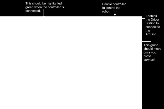
9 void loop() { //Continually communicates with the Robot Open Driver Station RobotOpen.syncDS(); Upload your code by pressing the arrow at the top of your sketch If an error occurs, check the Arduino Forums for help If no errors appear, proceed Unplug your Arduino from the computer Note: You will need to change the IP Address to fit your computer. For help with this see the Troubleshooting section. Configuring the Driver Station The Driver Station Open up the RobotOpenDS ( Go to: Setup > Robot > Type in the IP Address you made for the Arduino. The number for Port should be Plug in your Logitech Gamepad F310 (am-2046) Press any button on the Controller. The Joy #1 tab at the top of your Driver Station should be highlighted green. If not see the Troubleshooting section. Connecting the Robot and Driver Station Note: Check that your ethernet cable (am-0499) is plugged into your computer or router (am- 0839). Calibrating the Speed Controllers Hold the Arduino s reset button While holding the button, switch all of the speed controllers on Let go of the reset button Using the Controller Open up the RobotOpen Driver Station Make sure your controller (am-2064) is plugged into the computer Click the connect button in the top right corner of the Driver Station Click the enable robot button in the top right corner of the Driver Station Move your analog sticks. Your left analog corresponding to your left wheels & your right analog corresponding to your right wheels 9
10 Troubleshooting My program won t load onto my Arduino. OR I keep getting the error message: avrdude: stk500_getsync(): not in sync: resp=0x00? Check that you have the right com port. To do this: Unplug your FTDI cable from the computer Open the serial port menu Find which com port is missing Plug your FTDI cable back into the computer Re-open the serial port menu Select the new com port Check that your FTDI cable is correctly plugged into your Arduino: Completely unplug the FTDI cable from your Arduino Make sure that the golden crimps are facing down Fit the FTDI cable into the Arduino s FTDI Port Push the cable up until the silver pins are covered. Note: It may feel like the pins will break, but push the cable all the way. This ensures that you will achieve a good connection. Joy #1 on the Driver Station does not highlight when the controller is plugged in? Make sure the Driver Station window is open and Selected. If it still does not work, move to the next step. Re-connect the controller: Close the Driver Station App Unplug your controller from the computer Re-open the Driver Station App Plug your controller into the computer Press any button on your controller Repeat the process once more if it does not work the first time. 10
11 The Driver Station won t connect to the Arduino? OR The Driver Station only connects to the Arduino for a short time? Check to see if your Arduino IP Address is correct: Make sure you the code from Programming the Arduino section is loaded on to the Arduino, your Arduino is plugged in to your network and you have changed the IP Address to fit the subnet your computer is on. (Same first three numbers) Open start menu > search for cmd > select cmd.exe > type in: ping IPADDRESS -n 15 >Press Enter If it says Destination host unreachable you need to either: Change your IP Address Check the way you setup your software To find a correct IP Address: Open start menu > search for cmd > select cmd.exe > type in: ipconfig In the line that says "IPv4 Address" there should be a number You want your IP Address for your Arduino to have the same first three numbers of your IPv4 Address but a different last number For example: Your IPv Arduino IP or XX Re-install the software: Close all Arduino sketches Open up task manager and make sure no Arduino programs are running The application will be called Arduino r2 Open up the start menu > Control Panel > Programs and Features > Right-Click on Arduino > Select uninstall Open up your Downloads folder and delete your all of the downloaded files for Arduino and RobotOpen EXCEPT for your Driver Station Once everything is uninstalled and deleted, re-download the Arduino IDE & the RobotOpen Arduino Shield Software Open up your Downloads folder > Open RobotOpen-Shield-Library-master zip file > Open RobotOpen-Shield-Library-master file > Open libraries file > Right-Click on the RobotOpen file > Select Copy 11
12 Open up the start menu > Select Computer > Open Local Disk (C:) > Open up either Program Files (x64) or Program Files (x86) > Open Arduino > Open libraries > Right- Click in an open area > Select paste If you selected to install it to a custom area, you will go there instead of Program Files. Follow the steps from the Programming the Arduino section until the end 12

13 Appendix A: PWM A PWM is a message that allows your Arduino to talk to your speed controller which then controls your motor. This "message" is, in short, pulses of electricity every few milliseconds. Let's look at a theoretical analogy. Assume there is an army back before they had radio or any other type of speedy communication, and the army is split into two different sections. These two sections need a way to communicate but they are too far away for messengers, so they decide to use a flag. To make sure the two groups understand each other, they decide that every twenty minutes they will raise the flag with a message. The flag is raised for a minimum of one minute so the other section knows a message is coming. If the flag is lowered right after that first minute, that means retreat. If the flag is kept up for thirty seconds after that minute, that means don't move. If the flag is kept up for one minute after the first minute, that means to go forward. In this analogy, the period of the message is twenty minutes. After the message, the flag will go down until the next period starts. If we were to graph this, it would look something like this: How does this relate to your Arduino and Motors? Well think of your Arduino as the side sending the message and your speed controller as the other group receiving the message. Once your speed controller reads the message it controls the motor to do whatever the message said. The only difference between a PWM and the flag raising method is that a PWM uses electricity instead of a flag, and instead of minutes it uses milliseconds. 13
14 This is a variation to some of the code from above: //Adds Servo library to the compiler list #include <Servo.h> //Create a motor object to talk to Servo myservo; int d = 233; void setup() { //Tell the motor object to connect to myservo.attach(9); myservo.writemicroseconds(1500); delay(d); myservo.writemicroseconds(1000); delay(d); myservo.writemicroseconds(2000); delay(d); myservo.writemicroseconds(1500); void loop() { Most of this is straightforward except for the myservo.writemicroseconds() function. The myservo is the specific Servo Object we want to modify. The writemicroseconds() is the specific task we want to to with this object. The first part myservo just says that we are doing something with the servo that we call myservo. The second part writemicroseconds() is doing all the real work. writemicroseconds() takes the number we put in and uses that number to send the PWM. The number is the amount of time the pulse should be sent. You may have noticed the number we put in is in microseconds and not milliseconds like a PWM, but it doesn t make a difference. Now that you know all of this you should know: myservo.writemicroseconds(1500); says the motor is neutral. myservo.writemicroseconds(1000); says the motor is full reverse. myservo.writemicroseconds(2000); says the motor is full forward. myservo.writemicroseconds(1500); says the motor is back to neutral. The delay function just stops the motor from changing positions to quickly. Note : DO NOT change the value of "d" this number should be constant. The purpose of the above code is to perform a calibration, a type of "handshake." The speed controller does not really know the exact scale that your Arduino would send out pulses so it must find out the midpoint then the low and high point. It must also have enough time to register these values, hence the delay. The set delay time of 233 is the minimum amount of time the controller needs to register the values and that is why the number should not be changed. 14


15 The Driver Station 15

 and the right side runs in reverse (-100%).")
16 Appendix C: Motor Bias What is motor bias? Look at the picture below: The arrow is the way the wheel would move if in forward or reverse. Yet, what happens to a motor on the opposite side? Motors on opposite sides are the same kind of motor; one is just flipped 180 degrees. So, if we flip the above motor we get this: If you want both sides of your robot to run forward, the motors will be moving in opposite directions. So, to move your robot forward, the left side runs forward(100%) and the right side runs in reverse (-100%). The only problem is that when a motor runs in reverse (-100%), it does not always move as fast as a motor running forward. This is called a motor bias. So, to counter this you must slow down the motors moving forward to match the motors that are moving in reverse. To help you with this, we have created the bias() function in the program to help you. EXAMPLE: //We declare that we have a function that is going to take an integer int bias_ms (int motor){ //The motors move around 15% slower when in reverse. float reversebias =.85; //If the motor is moving forward we want to slow it down by 15% if(motor>neutral){ //Maps a new scale that will match the speed of the motors running in reverse return map(motor, REVERSE, FORWARD, (FORWARD_MS*(1.0- reversebias)+1000), (FORWARD_MS*reverseBias)); else { //Maps a new scale that will match the speed of the motors running in reverse 16
17 return map(motor, REVERSE, FORWARD, REVERSE_MS, FORWARD_MS); 17
Arduino 101 AN INTRODUCTION TO ARDUINO BY WOMEN IN ENGINEERING FT T I NA A ND AW E S O ME ME NTO R S
 Arduino 101 AN INTRODUCTION TO ARDUINO BY WOMEN IN ENGINEERING FT T I NA A ND AW E S O ME ME NTO R S Overview Motivation Circuit Design and Arduino Architecture Projects Blink the LED Switch Night Lamp
The Arduino Briefing. The Arduino Briefing
 Mr. Yee Choon Seng Email : csyee@simtech.a-star.edu.sg Design Project resources http://guppy.mpe.nus.edu.sg/me3design.html One-Stop robotics shop A-Main Objectives Pte Ltd, Block 1 Rochor Road, #02-608,
RoastLogger Arduino/TC4 driver installation for Windows 9/10/13 By John Hannon (JackH) at Homeroasters.org
 at Homeroasters.org") This procedure was written for the Arduino Uno board with the TC4 shield. Please check the Arduino site for software if you are using a different model. I have not tested it, but this procedure should
This procedure was written for the Arduino Uno board with the TC4 shield. Please check the Arduino site for software if you are using a different model. I have not tested it, but this procedure should
Arduino Programming and Interfacing
 Arduino Programming and Interfacing Stensat Group LLC, Copyright 2017 1 Robotic Arm Experimenters Kit 2 Legal Stuff Stensat Group LLC assumes no responsibility and/or liability for the use of the kit and
RedBoard Hookup Guide
 Page 1 of 11 RedBoard Hookup Guide CONTRIBUTORS: JIMB0 Introduction The Redboard is an Arduino-compatible development platform that enables quick-and-easy project prototyping. It can interact with real-world
ROBOTLINKING THE POWER SUPPLY LEARNING KIT TUTORIAL
 ROBOTLINKING THE POWER SUPPLY LEARNING KIT TUTORIAL 1 Preface About RobotLinking RobotLinking is a technology company focused on 3D Printer, Raspberry Pi and Arduino open source community development.
CORTEX Microcontroller and Joystick User Guide
 This is a User Guide for using the VEX CORTEX Microcontroller and VEX Joystick. Refer to the VEX Wiki (http://www.vexforum.com/wiki/index.php/vex_cortex_microcontroller) for updates to this document. 1.
Prototyping & Engineering Electronics Kits Basic Kit Guide
 Prototyping & Engineering Electronics Kits Basic Kit Guide odysseyboard.com Please refer to www.odysseyboard.com for a PDF updated version of this guide. Guide version 1.0, February, 2018. Copyright Odyssey
Note. The above image and many others are courtesy of - this is a wonderful resource for designing circuits.
 Robotics and Electronics Unit 2. Arduino Objectives. Students will understand the basic characteristics of an Arduino Uno microcontroller. understand the basic structure of an Arduino program. know how
1 Introduction. 1.1 Overview. 1.2 Supported Hardware. 1.3 Recommended Hardware. 1.4 Installation
 1 Introduction 1.1 Overview The RobotOpen Arduino Library provides an easy to use abstraction layer to quickly begin programming and controlling your robots with RobotOpen. The 1.0.x release is currently
Objectives: Learn how to input and output analogue values Be able to see what the Arduino is thinking by sending numbers to the screen
 Objectives: Learn how to input and output analogue values Be able to see what the Arduino is thinking by sending numbers to the screen By the end of this session: You will know how to write a program to
2009 FRC Control System. Published by Team 103
 2009 FRC Control System Published by Team 103 Section 1 Overview of Components crio DSC (Digital Side Car) Power Distribution Board Wireless Gaming Adapter Wireless Router Driver Station Speed Controllers
Tutorial 1: Software Setup
 1 of 5 11/21/2013 11:33 AM Shopping Cart Checkout Shipping Cost Download Website Home MP3 Player 8051 Tools All Projects PJRC Store Site Map You are here: Teensy Teensyduino Tutorial Setup PJRC Store Teensy
This is the Arduino Uno: This is the Arduino motor shield: Digital pins (0-13) Ground Rail
 Ground Rail") Reacting to Sensors In this tutorial we will be going over how to program the Arduino to react to sensors. By the end of this workshop you will have an understanding of how to use sensors with the Arduino
Reacting to Sensors In this tutorial we will be going over how to program the Arduino to react to sensors. By the end of this workshop you will have an understanding of how to use sensors with the Arduino
Robotics Adventure Book Scouter manual STEM 1
 Robotics Robotics Adventure Book Scouter Manual Robotics Adventure Book Scouter manual STEM 1 A word with our Scouters: This activity is designed around a space exploration theme. Your Scouts will learn
Create moving images in forward and reverse with your Arduino when you connect a motor to an H-bridge and some still images BATTERY POTENTIOMETER
 ZOETROPE Create moving images in forward and reverse with your Arduino when you connect a motor to an H-bridge and some still images Discover : H-bridges Time : 30 minutes Level : Builds on projects :
How to use the Zduino LEE Module with the Trainer Board
 How to use the Zduino LEE Module with the Trainer Board Note: If you are going to use the Arduino/Zduino module for this distance training workshop, please download the Arduino software: 1. Connections
AT42QT1010 Capacitive Touch Breakout Hookup Guide
 Page 1 of 7 AT42QT1010 Capacitive Touch Breakout Hookup Guide Introduction If you need to add user input without using a button, then a capacitive touch interface might be the answer. The AT42QT1010 Capacitive
VEX ARM Cortex -based Microcontroller and VEXnet Joystick User Guide
 1. VEX ARM Cortex -based Microcontroller and VEXnet Joystick Pairing Procedure: a. The Joystick must first be paired to the VEX ARM Cortex -based Microcontroller before they will work using VEXnet Keys.
Building an Arduino-powered underwater ROV
 Building an Arduino-powered underwater ROV An ROV offers an entirely different way to use Arduino to explore a new world. This project is a bit different in two ways. First, there is quite a bit of mechanical
Lab 01 Arduino 程式設計實驗. Essential Arduino Programming and Digital Signal Process
 Lab 01 Arduino 程式設計實驗 Essential Arduino Programming and Digital Signal Process Arduino Arduino is an open-source electronics prototyping platform based on flexible, easy-to-use hardware and software. It's
TA0139 USER MANUAL ARDUINO 2 WHEEL DRIVE WIRELESS BLUETOOTH ROBOT KIT
 TA0139 USER MANUAL ARDUINO 2 WHEEL DRIVE WIRELESS BLUETOOTH ROBOT KIT I Contents Overview TA0139... 1 Getting started: Arduino 2 Wheel Drive Wireless Bluetooth Robot Kit using Arduino UNO... 1 2.1. What
Software Setup Instructions for the Foster Control System used in the Explora Dome Observatories
 Software Setup Instructions for the Foster Control System used in the Explora Dome Observatories Contents Pages 3 & 4 The new tic counter system & home position sensor Page 5 Control Boxes Pages 6-8 Down
Digital Pins and Constants
 Lesson Lesson : Digital Pins and Constants Digital Pins and Constants The Big Idea: This lesson is the first step toward learning to connect the Arduino to its surrounding world. You will connect lights
INTRODUCTION TABLE OF CONTENTS 1 INTRODUCTION WELCOME TO THE 2009 FRC CONTROL SYSTEM Suggestions for Getting Started 2
 Section 1 INTRODUCTION TABLE OF CONTENTS 1 INTRODUCTION 2 1.1 WELCOME TO THE 2009 FRC CONTROL SYSTEM 2 1.1.1 Suggestions for Getting Started 2 1.2 TECHNICAL SUPPORT FOR THE 2009 FRC CONTROL SYSTEM 2 1.3
AT42QT101X Capacitive Touch Breakout Hookup Guide
 Page 1 of 10 AT42QT101X Capacitive Touch Breakout Hookup Guide Introduction If you need to add user input without using a button, then a capacitive touch interface might be the answer. The AT42QT1010 and
This is an inspection failure, not meeting the requirement of >10k Ohm between either PD battery post and chassis.
 Troubleshooting This is a document put together by CSA Laura Rhodes that contains a lot of information about troubleshooting steps for a lot of common control system problems encountered at events. No
Quickstart CHAPTER 1. Powering Up. Installing the Software
 CHAPTER 1 Quickstart THIS IS A CHAPTER for the impatient Evil Genius. Your new Arduino board has arrived and you are eager to have it do something. So, without further ado... Powering Up When you buy an
StenBOT Robot Kit. Stensat Group LLC, Copyright 2018
 StenBOT Robot Kit 1 Stensat Group LLC, Copyright 2018 Legal Stuff Stensat Group LLC assumes no responsibility and/or liability for the use of the kit and documentation. There is a 90 day warranty for the
Introduction to Internet of Things Prof. Sudip Misra Department of Computer Science & Engineering Indian Institute of Technology, Kharagpur
 Introduction to Internet of Things Prof. Sudip Misra Department of Computer Science & Engineering Indian Institute of Technology, Kharagpur Lecture - 23 Introduction to Arduino- II Hi. Now, we will continue
Counter & LED (LED Blink)
") 1 T.R.E. Meeting #1 Counter & LED (LED Blink) September 17, 2017 Contact Info for Today s Lesson: President Ryan Muller mullerr@vt.edu 610-573-1890 Learning Objectives: Learn how to use the basics of Arduino
1 T.R.E. Meeting #1 Counter & LED (LED Blink) September 17, 2017 Contact Info for Today s Lesson: President Ryan Muller mullerr@vt.edu 610-573-1890 Learning Objectives: Learn how to use the basics of Arduino
Make your own secret locking mechanism to keep unwanted guests out of your space!
 KNOCK LOCK Make your own secret locking mechanism to keep unwanted guests out of your space! Discover : input with a piezo, writing your own functions Time : 1 hour Level : Builds on projects : 1,,3,4,5
Freeduino USB 1.0. Arduino Compatible Development Board Starter Guide. 1. Overview
 Freeduino USB 1.0 Arduino Compatible Development Board Starter Guide 1. Overview 1 Arduino is an open source embedded development platform consisting of a simple development board based on Atmel s AVR
Lab 2.2 Ohm s Law and Introduction to Arduinos
 Lab 2.2 Ohm s Law and Introduction to Arduinos Objectives: Get experience using an Arduino Learn to use a multimeter to measure Potential units of volts (V) Current units of amps (A) Resistance units of
Thumb Joystick Retail. Tools and parts you'll need. Things you'll want to know. How does it work? Skill Level: Beginner. by MikeGrusin March 22, 2011
 Thumb Joystick Retail Skill Level: Beginner by MikeGrusin March 22, 2011 Thank you for purchasing our Thumb Joystick! Whether you're blasting aliens or driving a robot, you'll find it a very useful addition
CNC Controller Quick Start Guide
 CNC Controller Quick Start Guide Following this quick start guide should get you up and running. Refer to the Buildbotics Controller Manual for more complete descriptions. Things you need Buildbotics CNC
Elektor Uno R4 Installation & Test
 Elektor Uno R4 Installation & Test Prerequisites Elektor Uno R4 USB-A to micro-b cable Computer with Windows (XP or later), Linux or OSX (10.7 or later) Arduino IDE 1.6.7 or higher (not 1.6.8) We highly
Robotics Jumpstart Training II. EasyC: Software & Firmware Updates
 Robotics Jumpstart Training II EasyC: Software & Firmware Updates Objectives: Learn how to update EasyC Current Version: 4.2.1.9 Learn how to update Firmware VEX Joystick (Controller) VEX Microcontroller
HUB-ee BMD-S Arduino Proto Shield V1.0
 HUB-ee BMD-S Arduino Proto Shield V1.0 User guide and assembly instructions Document Version 1.0 Introduction 2 Schematic 3 Quick user guide 4 Assembly 5 1) DIP Switches 5 2) Micro-MaTch Connector Headers
The Robodox Guide to Multiple Cameras in FRC
 The Robodox Guide to Multiple Cameras in FRC Title Page # Introduction 1 Chapter 1: Powering Multiple Cameras 2 Chapter 2: Setting Up Multiple Cameras 4 Section 1: Setting Up First Camera 4 Section 2:
In this activity you will create a tool to allow you to play games such as Red Light/Green Light. To create the game, follow the steps below.
 Example: Hello World In this activity you will create a tool to allow you to play games such as Red Light/Green Light. To create the game, follow the steps below. If you get stuck, go to the Troubleshooting
Go-Baby-Go Senior Capstone Project
 Go-Baby-Go Senior Capstone Project Assembly Manual Team 22C Alwaleed Alhamra Asrar Alkhabbaz Fawaz Almutairi Sultan Almutairi Eric Trieu Project Sponsor: W.L. Gore & Associates Faculty Advisor: Dr. David
The "Hello world" of FRC robot programming
 The "Hello world" of FRC robot programming Here's how to create the shortest possible robot program that actually does something useful. In this case, it provides tank steering in teleop mode and drives
Make a Simple Weather Station Using Arduino
 Make a Simple Weather Station Using Arduino In this article, you will learn how to build your own weather station using the Arduino platform. This tutorial is based on the work from Steve Spence from Arduinotronics,
Arduino Prof. Dr. Magdy M. Abdelhameed
 Course Code: MDP 454, Course Name:, Second Semester 2014 Arduino What is Arduino? Microcontroller Platform Okay but what s a Microcontroller? Tiny, self-contained computers in an IC Often contain peripherals
Innovation First, Inc Full-Size Robot Controller Reference Guide
 2004 Full-Size Robot Controller Reference Guide 2.19.2004 www.innovationfirst.com Page 2 Table of Contents 1. Robot Controller Overview... 3 2. Main Power Input... 4 3. Battery Backup Power... 4 4. PROGRAM...
Step 1: Connect the Cortex to your PC
 This is a guide for configuring the VEX Cortex system to be programmed wirelessly using a VEXNet connection. These steps are required the first time you use your computer to program a specific VEX Cortex,
Introduction To Arduino
 Introduction To Arduino What is Arduino? Hardware Boards / microcontrollers Shields Software Arduino IDE Simplified C Community Tutorials Forums Sample projects Arduino Uno Power: 5v (7-12v input) Digital
Instruction Manual. Model RBA18
 Instruction Manual Model RBA18 The Robo-Arm Kit for Arduino is designed to teach the following: 1. How to build a mechanical arm, piece-by-piece. 2. Basic workings of mechanical arm 3. Coding and control
Arduino IDE The Developer Kit library The JeeLib library for RFM12 transceivers
 SKU: 810011 The aim of this project is to build a hydrogen powered remote temperature sensor. It is based on the Arduino, Developer Kit fuel cell shield, Maxim DS18B20 1 Wire temperature sensor, and the
Instructions for Installing FlashUpdate and Downloading Updates for Super Buddy Satellite Meter
 Instructions for Installing FlashUpdate and Downloading Updates for Super Buddy Satellite Meter Updates to the Field Guide and to the instrument firmware are available from the Applied Instruments website.
keyestudio Keyestudio MEGA 2560 R3 Board
 Keyestudio MEGA 2560 R3 Board Introduction: Keyestudio Mega 2560 R3 is a microcontroller board based on the ATMEGA2560-16AU, fully compatible with ARDUINO MEGA 2560 REV3. It has 54 digital input/output
Copyright White Box Robotics Inc. and Frontline Robotics Inc
 Disclaimer Working with electronics and installing the plastics will require care and patience. PROPER GROUNDING PROCEDURES before handling the electronics. Touching the robot chassis (which is common
Chapter 1: Getting Started
 Chapter 1: Getting Started Hello, and welcome to RBE 1001! This book will help you learn about how to use your Arduino to control a robot, including how to use various types of motors and sensors with
ZENSOL CIRCUIT BREAKER PERFORMANCE ANALYZER
 COMPUTERIZED TEST INSTRUMENTS ZENSOL CIRCUIT BREAKER PERFORMANCE ANALYZER CBA-32P QUICK SETUP GUIDE August 5th, 2013 1 CONTENTS CONTENTS... 2 STEP 1 REQUIRED MATERIALS... 3 STEP 1A ACCESSORIES... 4 STEP
Pulsed Frequency TM. Joint PEMF Software Download, Installation and User Guide
 Pulsed Frequency TM Joint PEMF Software Download, Installation and User Guide Account Registration... 3 Create an Account... 4 Download the Software... 6 Install the Software... 7 Connect JOINT PEMF to
VP- X Pro & VP- X Sport
 VP- X Configurator Release Notes As of version 1.6 (May 13, 2013) This document updated October 31, 2013 Contents 1. Models...1 2. Updating the VP-X Pro and Sport firmware (Automatic)...1 3. Software Upgrade
These instructions were adapted from Arduino: Installing Standard Firmata which is licensed under Attribution- NonCommercial-ShareAlike 2.
 These instructions were adapted from Arduino: Installing Standard Firmata which is licensed under Attribution- NonCommercial-ShareAlike 2.5 Generic Step 1: Download and Install Arduino Application Your
Physics 120/220. Microcontrollers Extras. Prof. Anyes Taffard
 Physics 120/220 Microcontrollers Extras Prof. Anyes Taffard Introduction 2 There are an infinite amount of applications for the Arduino. Lots of interfaces that can be controlled with it. Extension boards
The reasons for this problem might be: some special settings in the router itself or the switch might not be working properly.
 TROUBLESHOOTING If the Ethernet light is not on when the PC is connected to the switch by cable, please refer to this FAQ: What can I do if the Ethernet LED indicators on the Unmanaged Switch are off?
Docking Station Operational Description
 Docking Station Operational Description August 2018 Copyright 2017, 2018 All Rights Reserved Aures Technologies Changes: Ver 1.0, December 1, 2017, 1 st release Ver 1.1, January 11, 2018, add static IP
Halloween Pumpkinusing. Wednesday, October 17, 12
 Halloween Pumpkinusing Blink LED 1 What you will need: 1 MSP-EXP430G2 1 3 x 2 Breadboard 3 560 Ohm Resistors 3 LED s (in Red Color Range) 3 Male to female jumper wires 1 Double AA BatteryPack 2 AA Batteries
Rotorgeeks SSD Flight Controller Manual
 Rotorgeeks SSD Flight Controller Manual Please note this is a working document, we encourage you to visit this doc as it will continually evolve. It is intended as a guide to the SSD hardware rather than
Module 003: Introduction to the Arduino/RedBoard
 Name/NetID: Points: /5 Module 003: Introduction to the Arduino/RedBoard Module Outline In this module you will be introduced to the microcontroller board included in your kit. You bought either An Arduino
ROBOLAB Tutorial MAE 1170, Fall 2009
 ROBOLAB Tutorial MAE 1170, Fall 2009 (I) Starting Out We will be using ROBOLAB 2.5, a GUI-based programming system, to program robots built using the Lego Mindstorms Kit. The brain of the robot is a microprocessor
Arduino IDE Friday, 26 October 2018
 Arduino IDE Friday, 26 October 2018 12:38 PM Looking Under The Hood Of The Arduino IDE FIND THE ARDUINO IDE DOWNLOAD First, jump on the internet with your favorite browser, and navigate to www.arduino.cc.
GUIDE TO SP STARTER SHIELD (V3.0)
") OVERVIEW: The SP Starter shield provides a complete learning platform for beginners and newbies. The board is equipped with loads of sensors and components like relays, user button, LED, IR Remote and
OVERVIEW: The SP Starter shield provides a complete learning platform for beginners and newbies. The board is equipped with loads of sensors and components like relays, user button, LED, IR Remote and
Stand Alone HDMI Kit. Tutorial
 Stand Alone HDMI Kit Tutorial Table of Contents 1. WHAT'S IN THE KIT 2. HOW IT PLUGS TOGETHER 3. STANDARD STARTUP PROCEDURES 4. HOW TO OPEN AXIS(MACHINE CONTROL INTERFACE) 5. HOW TO OPEN A GCODE FILE FROM
Overview. Connect the Flight Control Board and Receiver
 Overview This article only describes the methods for connecting the receiver and ESC to the flight control board. You may need to refer to other materials for installation of other devices. If conditions
VEX Robot Remote Control Set-Up
 VEX Robot Remote Control Set-Up Note: Before proceeding with the VEXnet joystick setup on the following pages, complete these steps: 1) Open the RobotC program 2) Select File > Open Sample Program 3) Select
University of Hull Department of Computer Science C4DI Interfacing with Arduinos
 Introduction Welcome to our Arduino hardware sessions. University of Hull Department of Computer Science C4DI Interfacing with Arduinos Vsn. 1.0 Rob Miles 2014 Please follow the instructions carefully.
Arduino Panel Meter Clock. By Russ Hughes
 Arduino Panel Meter Clock By Russ Hughes (russ@owt.com) OVERVIEW My father has been a lifelong Ham Radio Operator with a fondness for almost anything with a panel meter. After seeing the Trinket Powered
Using a Stepper Motor Like a Servo Controlled by a Potentiometer (G Payne 2017)
") Overview: Using a Stepper Motor Like a Servo Controlled by a Potentiometer (G Payne 2017) Stepper Motors can be accurately controlled by digital pulses. They are typically geared. In this demonstration,
Overview: Using a Stepper Motor Like a Servo Controlled by a Potentiometer (G Payne 2017) Stepper Motors can be accurately controlled by digital pulses. They are typically geared. In this demonstration,
Documentation for Wifi-Enabled Data Logging - System Control By: Jesse Jenkins
 Documentation for Wifi-Enabled Data Logging - System Control By: Jesse Jenkins Code for this project is found on Github: https://github.com/hedronuser/metabolizer For getting started with Blynk, check
Create your own wireless motion sensor with
 Create your own wireless motion sensor with Arduino If you have a friend that has an alarm system in his or her home, I am sure you ve all seen these white motion sensors that are usually fixed above doors
Advanced Debugging I. Equipment Required. Preliminary Discussion. Basic System Bring-up. Hardware Bring-up, Section Plan
 Advanced Debugging I Hardware Bring-up, Section Plan Equipment Required 192 car Logic analyzer with mini probes, cable PC scope with probes, M-F breadboard wire, USB cable Voltmeter Laptop with mouse,
How-To #3: Make and Use a Motor Controller Shield
 How-To #3: Make and Use a Motor Controller Shield The Arduino single-board computer can be used to control servos and motors. But sometimes more current is required than the Arduino can provide, either
USER MANUAL ARDUINO I/O EXPANSION SHIELD
 USER MANUAL ARDUINO I/O EXPANSION SHIELD Description: Sometimes Arduino Uno users run short of pins because there s a lot of projects that requires more than 20 signal pins. The only option they are left
ARDUINO UNO R3 BASED 20A ROBOT CONTROL BOARD [RKI-1580] Page 1
![ARDUINO UNO R3 BASED 20A ROBOT CONTROL BOARD [RKI-1580] Page 1](/thumbs/73/69461282.jpg "ARDUINO UNO R3 BASED 20A ROBOT CONTROL BOARD [RKI-1580] Page 1") ARDUINO UNO R3 BASED 20A ROBOT CONTROL BOARD [RKI-1580] http://www.robokitsworld.com Page 1 1. Introduction: The Arduino UNO R3 based 20A robot control board is a versatile motor controller for driving
ARDUINO UNO R3 BASED 20A ROBOT CONTROL BOARD [RKI-1580] http://www.robokitsworld.com Page 1 1. Introduction: The Arduino UNO R3 based 20A robot control board is a versatile motor controller for driving
Reading ps2 mouse output with an Arduino
 Reading ps2 mouse output with an Arduino Kyle P & Mike K 4 / 24 / 2012 Our goal was to create a piece of equipment that senses how much a robot drifts left to right by using an optical encoder. Background:
KNOCK LOCK MAKE YOUR OWN SECRET LOCKING MECHANISM TO KEEP UNWANTED GUESTS OUT OF YOUR SPACE! Discover: input with a piezo, writing your own functions
 125 KNOCK LOCK MAKE YOUR OWN SECRET LOCKING MECHANISM TO KEEP UNWANTED GUESTS OUT OF YOUR SPACE! Discover: input with a piezo, writing your own functions Time: 1 HOUR Level: Builds on projects: 1, 2, 3,
FRC Driver Station Powered by NI LabVIEW
 This article describes the use and features of the 2016. For information on installing the Driver Station software see this document. Starting the FRC Driver Station The FRC Driver Station can be launched
Metro Minimalist Clock
 Metro Minimalist Clock Created by John Park Last updated on 2018-08-22 04:01:22 PM UTC Guide Contents Guide Contents Overview For this build you'll need: Clock Circuit Code the Clock Display the Clock
HUB-ee BMD-S Arduino Proto Shield V1.1
 HUB-ee BMD-S Arduino Proto Shield V1.1 User guide and assembly instructions Document Version 0.5 Introduction & Board Guide 2 Schematic 3 Quick User Guide 4 Assembly Guide 6 Kit Contents 7 1) Diodes and
Sten-SLATE ESP Kit. Description and Programming
 Sten-SLATE ESP Kit Description and Programming Stensat Group LLC, Copyright 2016 Overview In this section, you will be introduced to the processor board electronics and the arduino software. At the end
XM360 X-Tractor Troubleshooting
 XM360 X-Tractor Troubleshooting 1. Downloading X-Tractor PROBLEM: You encounter an error during the downloading process. ANSWER: Stop the download process and retry. If you continue to experience difficulties,
New APIs and Hacks. Servo API. Chapter 4. The Theory versus Practice
 Chapter 4 New APIs and Hacks The challenge when Intel Galileo was designed was to create a board that would be compatible with Arduino headers and reference language using only the Quark microprocessor,
Project 16 Using an L293D Motor Driver IC
 Project 16 Using an L293D Motor Driver IC In the previous project, you used a transistor to control the motor. In this project, you are going to use a very popular motor driver IC called an L293D. The
Arduino 05: Digital I/O. Jeffrey A. Meunier University of Connecticut
 Arduino 05: Digital I/O Jeffrey A. Meunier jeffm@engr.uconn.edu University of Connecticut About: How to use this document I designed this tutorial to be tall and narrow so that you can read it on one side
Pulsed Frequency TM. MR7 Software Download, Installation and User Guide
 Pulsed Frequency TM MR7 Software Download, Installation and User Guide Contents Account Registration... 3 Create an Account... 4 Download the Software... 6 Install the Software... 8 Connect MR7 to Your
Arduino Lesson 15. DC Motor Reversing
 Arduino Lesson 15. DC Motor Reversing Created by Simon Monk Last updated on 2017-03-09 04:04:43 PM UTC Guide Contents Guide Contents Overview Parts Part Qty An Experiment In1 In2 Motor Breadboard Layout
VEX Startup and Configuration Procedures
 VEX Startup and Configuration Procedures Power Up Open RobotC Step 2 Plug battery into the Cortex power port. The plug is keyed to only install one way. Black wire will face to the outside of the Cortex.
Controlling the Robotic Arm using the BBC micro:bit
 Controlling the Robotic Arm using the BBC micro:bit You need to plug the BBC micro:bit into a computer using a USB cable or sync to it using Bluetooth after downloading the correct app from your app store.
Rover 5. Explorer kit
 Rover 5 Explorer kit The explorer kit provides the perfect interface between your Rover 5 chassis and your micro-controller with all the hardware you need so you can start programming right away. PCB Features:
Station Automation --W3SZ
 Station Automation --W3SZ Now Back to Previously Scheduled Program USB-Serial IF/Transverter Bandswitch Arduino-VHFLog Example I started with Ed Finn WA3DRC s excellent code that was written to give TS2000
RC Tractor Guy Controller V2.1 Assembly Guide
 RC Tractor Guy Controller V. Assembly Guide Features 0 Push button inputs Dual axis thumb sticks with built-in push button Rotary encoders with built-in push button MCU Socket to suit Meduino Mega 560
Share Drobo on a Network: Apple Airport Extreme
 D R O B O A P P L I C A T I O N N O T E S E R I E S Share Drobo on a Network: Apple Airport Extreme This application note describes how we at Data Robotics share files wirelessly that are stored on a Drobo
SeeMeCNC Guides. Step 5: Installing the Firmware. This guide will show you how to install the firmware on your Rostock MAX v3 3D printer.
 SeeMeCNC Guides Step 5: Installing the Firmware This guide will show you how to install the firmware on your Rostock MAX v3 3D printer. Written By: geneb 2016 seemecnc.dozuki.com Page 1 of 7 Step 1 Download
Blinking an LED 1 PARTS: Circuit 2 LED. Wire. 330Ω Resistor
 Circuit PIN 3 RedBoard Blinking an LED LED (Light-Emitting Diode) Resistor (33 ohm) (Orange-Orange-Brown) LEDs (light-emitting diodes) are small, powerful lights that are used in many different applications.
Procedure: Determine the polarity of the LED. Use the following image to help:
 Section 2: Lab Activity Section 2.1 Getting started: LED Blink Purpose: To understand how to upload a program to the Arduino and to understand the function of each line of code in a simple program. This