Layla by. Owner s Manual Version 2.2 for Mac. Layla is designed and manufactured in the U.S. by Echo Corporation
|
|
|
- Olivia Anderson
- 6 years ago
- Views:
Transcription
1 Layla by Owner s Manual Version 2.2 for Mac Layla is designed and manufactured in the U.S. by Echo Corporation
2 Important Safety Instructions 1. Read Instructions - Be sure to read all of the safety and operating instructions before operating this product. 2. Retain Instructions - The safety instructions and owner's manual should be retained for future reference. 3. Heed Warnings - All warnings on Layla and in the Owner's Manual should be followed. 4. Follow Instructions - All operating and use instructions should be followed. 5. Moisture - Water and moisture are detrimental to the continued good health of Layla. Do not install or operate Layla near sources of water or moisture such as sinks, damp basements, leaky roofs, etc. 6. Heat - Layla should be situated away from sources of heat such as heaters or radiators. 7. Power Sources - This unit should be operated only from the type of power source indicated in this documentation or on Layla. If you are unsure about the type of power at your location, contact your local power company. 8. Grounding - Precautions should be taken so that the grounding capabilities of the Layla are not undermined. This equipment is provided with a cord having an equipment grounding conductor and grounding plug. This plug must be plugged into an outlet that is properly installed and grounded in accordance with all local rules and ordinances. Do not modify the plug provided with the equipment. If the plug will not fit into your outlet, have a proper outlet installed by a qualified electrician. 9. Power Cord Protection - Power supply cords should be routed so that they are unlikely to be walked on or pinched by items placed upon or against them. Pay particular attention to protecting the plugs, outlets, and the point at which the cord exits Layla. 2
3 10. Servicing - Do not attempt to service this unit yourself, as opening the case will expose you to hazardous voltage or other dangers. All servicing should be referred to qualified service personnel. 11. Damage Requiring Service - Unplug this unit and refer it to a qualified service technician when any of the following occur: a) Objects have fallen or liquid has spilled into the unit b) The product has been exposed to rain or water c) The product does not operate normally or when a marked change in performance is noticed d) The product has been dropped or damaged in any way 3
4 Sending in your registration card or registering online at - allows us to register key information so that we may handle problems faster and inform you of advance information on upgrades and other news. Thanks in advance for filling out your registration card and sending it to us. We hope you enjoy your Echo product. Limited Warranty Echo Corporation warrants this product, when purchased at an Authorized Echo Dealer in the United States of America, to be free of defects in materials and manufacturing workmanship for a period of one year from the date of original purchase. During the warranty period Echo shall, at its option, either repair or replace any product that proves to be defective upon inspection by Echo. Final determination of warranty coverage lies solely with Echo. Echo reserves the right to update any unit returned for repair, and reserves the right to change or improve the design of the product at any time without notice. This is your sole warranty. Echo does not authorize any third party, including any dealer or sales representative, to assume any liability on behalf of Echo or to make any warranty for Echo. Service and repairs of Echo products are to be performed only at the factory (see below) unless otherwise authorized in advance by the Echo Service Department. Unauthorized service, repair or modification will void this warranty. To obtain factory service: Contact Echo Corporation at (805) , 9AM to 5PM Monday through Friday (Pacific Time). If necessary, you will be given a return authorization number. Products returned without an RA number will be refused. Echo may, at its option, require proof of the original date of purchase in the form of a dated copy of the original authorized dealer s invoice or sales receipt. Pack the product in its original shipping carton and attach a description of the problem along with your name and a phone number where Echo can contact you if necessary. Ship the product insured and freight prepaid to: Echo Corporation 6460 Via Real Carpinteria, CA DISCLAIMER AND LIMITATION OF WARRANTY Echo Corporation makes no other warranties, express, implied, or otherwise, regarding Echo products, and specifically disclaims any warranty for merchantability or fitness for a particular purpose. The exclusion of implied warranties is not permitted in some states and the exclusions specified herein may not apply to you. This warranty provides you with specific legal rights. There may be other rights that you have which vary from state to state. In no event will Echo Corporation be liable for any lost profits, or for any consequential, direct or indirect damages, however caused and on any theory of liability, arising from this warranty and sale by Echo Corporation 6460 Via Real Carpinteria, CA Echo is a registered trademark of Echo Corporation Layla, Gina and Darla are trademarks of Echo Corporation Windows, Windows 95, Windows 98, and Windows NT are registered trademarks of Microsoft, Inc. Macintosh, Power Mac, G3 and Power PC are registered trademarks of Apple Computer, Inc. 4
5 Table of Contents Introduction 6 What You Should Have Received in the Layla Box 6 System Requirements 6 Layla Installation 7 Checking your Macintosh 7 Install 3 rd Party Multitrack Software 7 Configuring your Macintosh System 8 Installing the Layla Hardware 13 Connecting to Layla s Rack-mount Interface 16 Running the Echo Card Installer 21 Layla Audio Input & Output Devices 23 Custom Install: Additional ASIO and OMS Drivers 24 ASIO Driver Configuration 25 OMS Setup 25 The Echo Console 28 The Options Menu 29 Console Controls 31 Monitor Controls 32 Adjusting Record Levels 33 Setting Clock Sources and Destinations 33 Synchronizing Multiple Devices 34 Contacting Customer Service 37 Appendix A: Introduction to Digital Audio 38 Appendix B: Specifications 42 Index 43 5
6 Introduction Thank you for choosing the Layla 20-bit Multitrack Digital Audio Recorder. We think you ll find Layla to be an extremely flexible, high-performance tool for your computer-based hard disk recording system. What You Should Have Received in the Layla Box When you opened the Layla box, you should have found the following: A Layla PCI card wrapped in an anti-static cover A Layla rack-mount audio interface box A Layla digital control connector cable A compact disc containing the Macintosh Installer and demo versions of digital audio recording, editing, and processing software from a variety of manufacturers. The Layla Owner s Manual Four adhesive backed rubber feet and four mounting screws with collars. System Requirements In order to use Layla you ll need the following: An Apple brand Macintosh computer with a 604 or higher processor (G3 highly recommended). Our latest drivers now support the Apple Macintosh 1999 G3 s (Yosemite). We will not be able to supply technical support for any non-apple brand Macintosh clone computers. A fast, high-capacity IDE or SCSI hard disk drive An audio software program that uses ASIO: Cubase VST, VisionDSP, etc. Peripheral audio equipment, such as a mixer, power amplifier, DAT recorder, musical instruments, cables, etc. 6
7 Layla Installation Complete Layla installation consists of performing a system check, installing any multitrack recording software, configuring your Macintosh for multitrack audio, installing the Layla PCI card, connecting the rack-mount audio interface to the card, running Install Echo Card and, if necessary, installing additional ASIO and OMS drivers. Checking your Macintosh 1. Do you have enough Memory? With your mouse select Apple About this computer. Look at the amount of Built-in Memory you have. You will need to have at least 64Mb to use Layla in your computer. It is highly recommended that you have more. 2. Is your Processor fast enough? Select Apple System Profiler from the Apple menu. Look at the section entitled Hardware overview and see what kind of processor you have. If it s a PowerPC 604 or higher, then you can use the Layla. 3. Do you have an open PCI slot? Make sure that you have an open PCI slot in your Mac. If you don t know offhand, you will have to open up the Mac and look. Make sure you shut down the Mac and unplug the power cable before you open it. If you see an open PCI slot, then you re OK. If your system checks out OK, it s time to move on to the next phase of installation. Install 3 rd Party Multitrack Software If you haven t already, we recommend that you install any 3 rd party software now. This is not essential, but it will help when installing the Extensions and drivers for Layla later. 7

8 Configuring your Macintosh System 1. Check your Boot Disk. Most people only have one OS on their Mac, so they can ignore this section. If you have multiple hard drives with separate OSs in your Mac, then you will have to install the Layla software separately for each OS. To check your boot disk, go to Apple Control Panels Startup Disk. Make sure that the drive you want to boot from is highlighted. If you have changed this selection, you will have to restart for it to take affect. 8

9 2. Turn Virtual Memory Off. Turn RAM Disk Off. Go to Apple Control Panels Memory. Where it says Virtual Memory, click Off. While you re here, make sure that RAM Disk is also Off. These settings are necessary for the Layla software to work properly. 3. Make Alias for Sound Control Panel. Now you are going to install a helpful sound utility. Double click on your boot disk (if you have more than one hard drive and don t know which one this is, see #1 above). Now open the Apple Extras folder, and then open the Sound Control Panel folder. Here you will see a program called Sound. Highlight it by clicking on it once. Now select File Make Alias, and then do it a second time. Now drag both of the aliases to your desktop. Go back to the boot disk and open System Folder, and find the folder called Control Panels. Drag one of the aliases into the Control Panels folder. Now you can access the Sound Control panel from your desktop or from the Apple Control Panels menu. 9

10 4. Set Sound In and Sound Out to Built-in. Open the Sound Control Panel. You can do this by double clicking the alias you just created and put on your desktop. Select Sound In from the drop down menu. Highlight Built-in by clicking on it. Now select Sound Out from the drop down menu. Highlight Built-in by clicking on it. Both of these settings may have already been set to Built-in, but it s good to make sure. 5. Turn Off Folder/Menu Sounds. This is optional, but highly recommended. If you leave these on, then some audio programs (like Cubase VST) may not function as well as they could. Go to Apple Control Panels Appearance. Click the Sound tab. In the Sound Track menu select None. If you had a sound scheme selected before, you would have heard sounds accompanying every mouse click and drag. Now you should hear nothing. 10
11 6. Mute/Turn down Built-in Volume. This is also optional, but highly recommended. If you leave the Built-in volume on, the alert sounds could interfere with a live recording using an ASIO program. Open the Sound Control Panel by double clicking the alias on your desktop (The one you created in step 3). Select Volumes from the drop down menu. Move the slider for Built-in to the bottom, and make sure there is a check in the Mute box. 11
, and click OK.")
12 7. Create an Audio Extensions Set. You need a separate Extensions Set with certain Extensions disabled so that your audio program can perform at its best with the Layla system. First, select Apple Control Panels Extensions Manager, and click the Duplicate Set button. Type in a name (like Audio Settings), and click OK. Now scroll down the list of Extensions and disable all of them that have to do with networking, printing, and any that say OpenTransport or OpenTpt. You disable an Extension by clicking the corresponding On/Off checkbox so that it is empty (meaning Off). Once you are done, click the Restart button and your Mac will restart using your new Audio Extensions Set. If you ever want to switch back to your previous Extensions Set, go to the Extensions Manager, select it from the Selected Set drop down menu, and click Restart. When your Mac restarts, you will now be able to use any printers or networking functionality you had before you started. When you want to use your Audio program again, just select the Audio Extensions Set and restart. 12
13 Installing the Layla Hardware Once you have checked your system requirements, verified that there are no problems with your system, installed any 3 rd party audio software, and have configured your Macintosh for multitrack audio, it is time to install Layla into your computer. Please refer to the section in your Mac manual for installing a PCI card. IMPORTANT - Unplug your computer and detach all peripherals before proceeding with the following steps. 1. Remove your computer s cover. This operation differs from computer to computer. Refer to your computer s manual for a further explanation of this step if necessary. 2. Select the slot into which you will install the Layla card. You may use any of the available PCI slots in your computer for Layla. Remove the bracket covering the expansion slot where you would like to install Layla. If there was a screw for the bracket, put it in a safe place, as you will need it later to complete installation. 3. Insure that you have fully discharged all static electricity from your body before handling the Layla card. This can be done through the use of a grounding strap or, more simply, by touching your bare hand to the metal casing of the computer s power supply. (For this latter method to work, the computer must be plugged in, though not turned on. After you ve discharged your static, unplug the computer before proceeding to the next step.) 4. Insert card into slot. Remove the Layla card from its protective antistatic bag. Handle the card carefully by its edges and insert it into the selected expansion slot. Insure that the card s edge connector (the protruding edge with the gold leads) is seated firmly into the slot. Centering the card over the slot and using a gentle rocking motion while pushing downward into the slot generally works well. Be careful not to force the card into the slot, or bend or twist it while it is being inserted, as this could result in the card being damaged. 13
14 5. Secure card to computer. If there was one, use the screw removed earlier from the protective backplate to attach the metal bracket at the back of the Layla card to the computer s rear panel. On many Macs the locking mechanisms used to hold down the PCI cards cause difficulties properly seating the cards. We recommend checking the card and making sure it is well seated and liable to stay that way. If the card is loose or being pushed around by the locking Mechanism, we recommend loosening the hex screws that hold the back-plane of the card to the Mac, that thin metal piece that sits against the case of your computer. Another option, if that piece needs a little more play, gently bend it back. Some users have broken the plastic that comes with their Mac to solve this problem. However, due to Mac warranty issues, we are not able to recommend this approach. 6. Replace the computer s cover and secure it. Please refer to your Mac manual for instructions. Reattach its power supply cord and reconnect any peripherals that you may have removed prior to beginning the Layla installation. 7. Locate the Layla rack-mount interface and the 25-pin audio connector cable. Securely mount the interface into your equipment rack. If you will not be mounting the box in a rack, remove the backing from the four rubber feet and place one in each bottom corner of the interface unit. Then be sure to locate the rack-mount box in a secure location. Plug one end of the cable into the 25-pin connector on the Layla card that now protrudes through the back panel of your computer, and secure the cable using the built-in screws located on both sides of the connector. Attach the other end of the cable to the rear of the interface and fasten the cable securely with the screws. Caution: Never connect the rack-mount interface to the computer while either the interface or your computer is turned on. 8. You can now attach external audio devices to the rack-mount box. Layla can accommodate eight analog input signals and can generate ten independent analog output signals. In addition, Layla provides word clock/superclock sync, MIDI in/out/through, and stereo S/PDIF digital input and output. Additional information on attaching external devices to Layla may be found in the Connecting to Layla s Rack-mount Interface 14
15 section. (NOTE: When connecting devices to the S/PDIF jacks on Layla, do not use standard RCA audio cables. For reliable S/PDIF operation, 75ohm coaxial video cables are recommended). All of the analog and digital inputs and outputs on Layla are simultaneously active, allowing you to record up to 10 channels of audio (eight analog and two digital) while playing back twelve channels (ten analog and two digital). 15

16 Connecting to Layla s Rack-mount Interface The back panel of Layla s rack-mount interface contains a wide variety of connections that allow great flexibility in the operation of Layla. To achieve the optimal performance with Layla, it is critical that the appropriate cabling and connectors are used. Analog Inputs and Outputs Layla has eight analog inputs and ten analog outputs on the back panel, as well as two inputs on the front (the two inputs on the front are alternate connectors for channels 7 and 8 on the back of Layla. When you plug into the front panel inputs, the corresponding back panel inputs are disabled). These connections can accept balanced or unbalanced signals. An unbalanced signal contains two components, a ground signal and a hot or active signal. A balanced signal contains these two components with the addition of a second active channel that is 180 degrees out of phase from the primary signal. In this way, a balanced signal can eliminate any noise that may be introduced into the audio signal during transmission. The connectors used for the analog inputs and outputs on Layla are TRS (tip, ring sleeve). The three sections of a TRS connector are used to transmit the three components of a balanced signal. Layla will also accommodate the two conductor unbalanced style connector. 16


17 The Host Connector Next to the analog inputs and outputs is a connector labeled HOST. This connector is known as a DB-25, and is commonly used on PCs for the printer port. It is the point at which the audio interface connects to the Layla PCI card inside your computer. A cable was supplied with your Layla for this purpose. This cable is manufactured to certain specifications, and if necessary, should only be replaced with a cable that meets specification IEEE Layla is designed for use with cables of up to 15 feet in length. Cables in excess of 15 feet may cause loss of data and/or diminished system performance. S/PDIF Next to the Host connector is a pair of connectors labeled S/PDIF in and out. S/PDIF is used to transmit digital data among digital audio devices. S/PDIF data can use the full 24-bit sample width used internally on Layla. When connecting devices to the S/PDIF jacks on Layla, the use of standard RCA audio cables is not recommended. For reliable S/PDIF operation, 75ohm coaxial (RG59) video cables are recommended. 17


18 Word Clock Next to the S/PDIF ports are the Word Clock connectors. These connectors allow you to synchronize one Layla to another Layla or to other digital audio devices. In addition to a standard word clock signal, these connectors also allow you to synchronize using the superclock format, which is 256x the selected sample rate. The word clock I/O uses a BNC connector. As with the S/PDIF I/O, a shielded 75 ohm (RG-59) coaxial video cable should be used. BNC connectors are widely used in the electronics industry for both video and computer networking. However computer networks use 50 ohm (RG-58) coaxial cables and not the 75 ohm (RG-59) cable used by video. For reliable word clock operation, use only video cables with Layla. MIDI The last set of connections to the Layla interface is for MIDI. The MIDI ports can be used for receiving MIDI time code (MTC), sending MIDI signals from your digital audio/midi sequencing software to external sound modules, etc. MIDI cabling is highly standardized and widely available. 18

19 The diagrams on the following two pages illustrate sample configurations using Layla and external audio equipment: 19
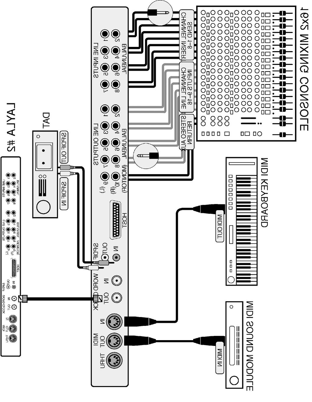
20 20

21 Running the Echo Card Installer Now that you have completed the hardware installation, you need to run the installer for the Layla to interact properly with the MacOS and your audio recording application. What the installer does: Deletes the EchoCard Extension if a previous version exists Deletes the EchoConsole if a previous version exists Copies the Layla Echo Card extension to the system folder Creates the Echo Card Folder and puts the Echo Console in it Copies the Layla ASIO Driver Copies the Layla OMS Driver Insert the Layla Mac Installation CD into your CD-ROM drive. Double click the icon called Install Echo Card. Read the Release Notes that appear so that you will be aware of any important updates. If you want to read it later, you will find a Read Me file in the Echo Card Folder after installation. After you re done with the Release Notes, click Continue. You will see a message saying Preparing to install and the installer may take several minutes before it continues, so please be patient. After a while you will see a new box that says Easy Install. You will want to keep this setting and press the Install button. 21


22 Now select where you want the Echo Card Folder to be installed. The default is to your desktop. You will get a message about restarting after installation Press Yes to continue. Now you will see the installer working, and then you will be asked which ASIO folder you want to install the Layla ASIO Driver to. If you have more than one audio program that uses ASIO, then you will have to select one folder, and then come back later to install the ASIO driver to your other program(s). You will find instructions on how to do this in a following section. Once you have selected a folder, press the Select button. 22
23 You should now see a message saying Installation was successful. Press Restart and make sure the power to the Layla rack mount box is on. It may be a good idea to turn down your mixer at this point, as there can be some noise when restarting. During restart, the red Echo Extensions Icon should appear on the lower left corner with your other extensions. If you don t see the red icon, check to see if there is a space for that icon. Some video cards for the Mac have a problem where they repaint the screen, hiding our little icon from sight. However, the space will still be there for the icon. This does not affect the performance of the Layla system. There should be one icon for each Echo Card in your computer. If this is not the case, then the card probably isn t being recognized by your Mac. Shut down your Mac, and make sure the card is seated properly in the PCI slot. Go back to the hardware installation section for instructions on how to do this. After the system has booted, go into Sound Control Panel and make sure that the card is there. You can do this by double clicking the handy alias you created earlier. Look in Sound In and Sound Out. If you don t see it here, you may not have installed the card properly. Layla Audio Input & Output Devices Now do a quick sound check. First, go to the Echo Card Folder you installed earlier. Open it and double click the Echo Console icon. ***WARNING - IMPORTANT*** This will set the Layla hardware to unity gain. You will need to do this after every restart or else the Layla volume levels will be extremely loud. Don t hurt your ears!! Now go into Sound Control Panel Sound Out and select Layla. Now select Alert Sounds. Make sure the volume levels aren t too high, and click a sound. If you have the Layla hardware set up properly to a set of speakers, then you should hear the sound. If you don t, then double check your cables and try again. If you hear a sound then you have succeeded in installing Layla!! Give yourself a pat on the back. Important - remember to switch Sound Out back to Built-In!!! 23

24 Custom Install: Additional ASIO and OMS Drivers If you have several audio programs that use ASIO, then you will need to install the Layla ASIO Driver to the corresponding ASIO folder for each program. You should have already installed the Layla ASIO Driver to one of these programs as part of the installation process above. Open the Layla Mac Install CD and start the Install Echo Card program just like you did earlier. Follow the instructions from before until you get to the part with the Easy Install. Remember, you may have to wait a while. Click on the box that reads Easy Install, and select Custom Install. Now you should see several installation options. Depending on what you want to install, click the appropriate checkbox or boxes. If you just want to install the ASIO Drivers, then just click that checkbox and leave the other ones empty. Press Install. You will now see the Select ASIO folder window. You can only select one folder at a time, so if you have more than two audio programs that use ASIO you will have to come back and do this again. After you have chosen a folder, press Select. If you want to install some more Layla drivers click Continue. If you are done, click Quit. Just one more step and you ll be making music with ASIO. 24

25 ASIO Driver Configuration You have now finished installing the Layla ASIO Driver to all of your audio programs that use ASIO. You now need to select the Layla ASIO Driver from within your audio program. Please refer to your audio program manual for instructions on how to do this. OMS Setup If you have OMS for MIDI, then you will need to run OMS Setup to allow your audio programs to use the Layla OMS Driver. Please keep in mind that this section is just an aid to the instructions in your OMS manual. First, you will need to find the Opcode folder on your hard drive where you installed OMS. Open it and then open the folder called OMS Applications. Find OMS Setup and double click it. Go to the File menu and click New Studio Setup. Click OK. A new window will come up. Click Search. OMS will search for any new equipment, and then you should see Layla recognized in a window like this: 25


26 The OMS Driver Setup window recognizes MIDI hardware drivers in your system. If there is something missing, then refer to your OMS manual and follow the instructions. If everything is OK, then click OK. Now you will see the OMS MIDI Device Setup window. 26

27 This window recognizes any MIDI devices (like synthesizers) currently attached to your system through your MIDI hardware (like Layla). In the example you can see that an MU5 Tone Generator is attached to the system through Layla. Scroll down and make sure everything is OK. If there is a problem, or you need to edit your setup, then refer to your OMS manual for instructions. If all is well, click OK. Now you will be asked to save the new studio setup. You can overwrite your old setup with the same name or create a new one. Click Save when you re done and you ll see a window displaying your new setup. If you want to test your new setup, go to the Studio menu and click Test Studio. Your mouse pointer will turn into a musical note. In the Setup window, click on a tone generator or synth. If it s turned on and hooked up properly, then you should hear a sound coming out of the MIDI devices outputs. If you do, then you re all done. We hope you enjoy the Layla multitrack digital audio recording system. This completes the installation of the Layla hardware and software. 27

28 The Echo Console Included with your Layla is a virtual control surface application called The Echo Console. The Console allows you to control the audio I/O and clocking functions of Layla, and it brings these controls to a single easy-to-use location. From the Console you can control input levels, select synchronization clocks, and adjust input monitoring. The Echo Console software can be found in the Echo Card Folder that was created during installation. Double clicking on the Echo Console icon will activate the console program. It should look like this: The console functions are grouped into three areas: clock selection (at the very top), input levels and trims (occupying the top half), and monitor channels (at the very bottom). 28
29 The Options Menu The first option, General, is greyed out because it is not currently supported. It will be available in a future release. The second and third options are Set Input +4/-10 and Set Output +4/- 10 These options produce two similar windows that (except for the words input/output) look like this: The Analog Input window lets you choose how the gain level is displayed, whereas the Analog Output window lets you choose the actual level of gain output for each of the analog outputs on Layla. In this way, devices with differing nominal operating levels are easily accommodated, and their input gain levels properly displayed on the Echo Console. 29
30 The fourth option is MTC Settings and the window looks like this: The MTC refers to MIDI Time Code. Because of the somewhat coarse resolution of MIDI Time Code, and its ability to exhibit wow and flutter (fluctuations in timing and consistency), the sync signal may sometimes stray from optimal. The Layla driver will automatically correct for these inconsistencies. When and how these corrections are made is configurable. The Tolerance setting lets you select how far you want to allow the synchronization to stray before a correction is made. Many times, if left alone, the sync may correct itself by first straying in one direction and then going back the other way. If the tolerance is set too low, Layla will correct the synchronization too frequently. This produces frequent jumps to correct the clock, introducing jitter. If the tolerance is too high, the synchronization will shift too far before a correction is made, which will also yield unsatisfactory results. The Damping setting lets you configure how quickly the corrections described above take place. Once Layla has determined that a correction is needed, a low damping level will effect the correction rapidly. A high level of damping causes the correction to occur in a more gradual nature. If you feel that a change is needed in the defaults for these settings because of poor MTC synchronization, it is generally wise to adjust the Tolerance setting first. Use the Damping adjustment if you are unable to obtain satisfactory results with the Tolerance setting. 30

31 The fith and sixth options are S/PDIF Pro and S/PDIF Consumer. Layla can transmit digital information in either of two modes, professional or consumer. The primary difference between the two is in the implementation of the SCMS copy-protection bit, which, in the consumer format, prevents the user from making digital copies of a digital copy. Layla s S/PDIF output defaults to the Consumer mode. If you are recording from Layla into a professional DAT deck, the deck may not be able to recognize the signal until you switch Layla s output to Professional mode. These options allow you to select which mode Layla transmits. In the options menu that appears you ll see a check next to S/PDIF Pro or S/PDIF Consumer. The mode that is checked is the current one. Select the appropriate mode for your DAT (if you don t know which one to use and are having difficulties, simply try the one that is not currently checked). Important note: Layla never transmits the SCMS bit, regardless of which mode is selected. Console Controls Let s take a look at the control surface. The Input Levels are located in the upper portion of the console surface. Directly below the Input Levels are the Input Trims. For each level meter there is a knob below it for input gain attenuation. Below every knob is a display that shows the currently selected level of attenuation or gain. You 31

32 can change the gain level by clicking in the display and typing, by clicking the arrows, or by click holding the knob and dragging right or left. You can also zero the level by holding the Command button on your keyboard and clicking the knob. Monitor Controls Below the Input Levels and Input Trims are the Monitor Channel controls. The input monitor controls allow you to monitor the record input signal via any of the available outputs on your Layla. Each input channel has a corresponding monitor output channel directly below it on the console. The monitor controls look and function similar to the controls for input. Note the addition of a Mute button to each channel. There is also a group of numbered buttons on the bottom left. These buttons allow you to select an output channel. When button 1 is selected, all of the monitor controls affect what goes to output 1. Note that it says Out 1 at the bottom of every channel. This will change according to whatever button is selected. The console will remember the changes you have made to each output even though you can only see one at a time. Take note that these controls are for the routing of audio signals from the Layla inputs to the Layla outputs only. The console does not control output that is generated by your computer (such as aiff files). That is controlled by whatever audio program(s) you may have. Remember that all of the inputs are continuously monitored by all of the outputs at some level. The degree of attenuation (or muting) of that level is set by the monitor controls. The console program constantly maintains a level setting for each of the 120 monitor paths it controls. Clicking on an output selection button simply selects the settings that are displayed. 32

33 Adjusting Record Levels Layla s input volume adjustments are made in the digital domain. When you lower a volume slider, you are actually decreasing the number of available bits, thereby taking away from the potential dynamic range of the system. To avoid this, we suggest that whenever possible you leave the output sliders set to their maximum positions, and perform any necessary attenuation on your external mixer. When the playback volume controls in your audio program are set to maximum and the input signal approaches the maximum pre-clipping level, you can achieve the full 20-bit dynamic range of the system. Setting Clock Sources and Destinations At the very top of the Console there are buttons that allow you to select the synchronization clocks that are used by Layla. The console program will sense which input clocking options are available, and automatically disable those that are unavailable. On the right are the output clock options. Here you can select from standard word clock or super clock (word clock x 256) output. To the left of the output clock selections are the input clock options. Depending on what external devices you have connected to Layla, you may have as many as five options here. 33

34 If you are unsure which clock synchronization selections are appropriate for your installation, be sure to read the next section, which deals with the types of clocks that Layla supports. Synchronizing Multiple Devices Layla is designed to work alongside other audio equipment within a complete Macintosh system. If you are planning on using Layla with other audio equipment, please note the following: The Layla Macintosh drivers included in this package currently do not support multiple Laylas within the same system. Future driver versions will support multiple Laylas in the same system. Fortunately, your new Layla will operate with Gina and Darla in the same system. Layla can also peacefully coexist with audio equipment from other manufacturers, but be aware that operating alongside another product is not the same as operating with it. In order for accurate synchronization to occur, the other audio product(s) in your system must support a synchronization mode (word clock, super clock, etc.) that is compatible with Layla. Without such synchronization, the individual pieces of equipment will act independently of each other. This scenario may be fine for some musical applications; however, it is not appropriate for situations where sample-accurate synchronization is required. For this reason, Layla supports many synchronization modes. Layla can slave to word clock, superclock, S/PDIF, and MIDI Time Code (MTC). In addition, Layla can also generate these synchronization signals, as well as perform translation of one clock to another, such as transmitting super clock while reading MTC. 34
35 Let s take a brief look at the various synchronization types. Word Clock This is a synchronization signal that connects to the BNC connector labeled Word Clock on Layla s back panel. This synchronization clock runs at the selected sample rate. Think of it as a kind of electronic metronome, which can click back and forth at speeds surpassing 48,000 times a second. It is one of the most widely used forms of synchronization in digital audio. Super clock This signal comes from Layla s Word Clock connector too. Its signal runs at 256 times the sample rate. A lot of equipment, including Layla, uses a 256x word clock internally. Using super clock allows the equipment to synchronize more accurately and adjust more rapidly to different sample rates. Note: A lot of equipment, including many clock synchronizers, generate super clock using a phase lock loop or PLL circuit. This can produce a super clock with a lot of jitter, which can cause noise on Layla s (and other) analog converters. Layla has a low-jitter clock generated using digital synthesis techniques. It is recommended that word clock be used when slaving Layla to other external equipment, reserving super clock for synchronizing multiple Laylas together. S/PDIF The Sony/Philips Digital Interchange Format is a serial bit-stream that has a clock signal embedded in the data stream. When recording from a S/PDIF source, Layla will utilize the synchronization clock that is embedded in the S/PDIF while it decodes the bitstream. Note: When recording from an S/PDIF port, you must select S/PDIF as the input clock. For greater flexibility, this is not done automatically. If you find that your S/PDIF recordings contain pops or skips, be sure that you have selected S/PDIF as your input clock. MIDI Time Code (MTC) MIDI time code differs from the preceding synchronization methods. Instead of simply providing the rate at which things should proceed, it transfers information in an elapsed time format (HH:MM:SS.) In addition, MTC also transmits a frame number to give the fine definition that is needed. This longitudinal format has the benefit of 35
36 including positional information; however, over time it tends not to maintain as tight a sync as sample based synchronization techniques. Now let s take a look at some possible configurations and how you might set them up from a synchronization standpoint. Let s start simple. Suppose that Layla is the only audio device used in your system. Since you have no other devices to synchronize with, simply select Internal for Layla s input clock. Layla will then use its own clock to control its operation. Now a little more complicated set-up: You have two Laylas connected. Simply set Layla #1 to Internal for its input clock and superclock for output. Now connect the first Layla to the second one via a BNC cable running from Word Clock Out on Layla #1 to Word Clock In on Layla #2. Now select superclock for Layla #2 s input synch. Your Laylas will now operate in unison. No matter how many devices you are synchronizing, the concept is essentially the same. You are merely daisy-chaining devices together using compatible clocks. One device will operate as the source of the master clock, with each successive device using that clock to sync. 36
37 Contacting Customer Service If you experience any trouble with your Layla system please go to the support area of our website at and check out the troubleshooting FAQ s we have there. If you can t find a solution to your problem there, please fill out the provided technical support form. This form will be sent to our technical support staff and they will respond to you quickly. Please fill out the form completely. We will not respond to you unless you fill out the form in its entirety. We cannot help you unless you give us the required information. We do ask you to please read through this manual and the support area of our website before contacting us. Thank you for buying Layla! 37
38 Appendix A: An Introduction to Digital Recording Converting Sound into Numbers In a digital recording system, sound is represented as a series of numbers, with each number representing the voltage, or amplitude, of a sound wave at a particular moment in time. The numbers are generated by an analog-todigital converter, or ADC, which converts the signal from an analog audio source (such as a guitar or a microphone) connected to its input into numbers. The ADC reads the input signal several thousand times a second, and outputs a number based on the input that is read. This number is called a sample. The number of samples taken per second is called the sample rate. On playback, the process happens in reverse: The series of numbers is played back through a digital-to-analog converter, or DAC, which converts the numbers back into an analog signal. This signal can then be sent to an amplifier and speakers for listening. In computers, binary numbers are used to store the values that make up the samples. Only two characters, 1 and 0, are used. The value of a character depends on its place in the number, just as in the familiar decimal system. Here are a few binary/decimal equivalents: BINARY DECIMAL ,535 Figure A. Binary numbers and their decimal equivalents Each digit in the number is called a bit, so the numbers in Figure A are sixteen bits long, and the maximum value which can be represented is 65,
39 Sample Size The more bits that are used to store the sampled value, the more closely it will represent the source signal. In an 8-bit system, there are 256 possible combinations of zeroes and ones, so 256 different analog voltages can be represented. A 16-bit system provides 65,535 possible combinations. A 16- bit signal is capable of providing far greater accuracy than an 8-bit signal. Figure B shows how this works. Figure B. The more bits there are available, the more accurate the representation of the signal and the greater the dynamic range. Layla s analog inputs use 20-bit ADCs, which means that the incoming signal can be represented by any of 1,048,576 possible values. The output DACs are also 20-bit; again, 1,048,576 values are possible. The S/PDIF inputs and outputs support signals with up to 24-bit resolution (16,777,216 possible values). Layla processes signals internally with 24-bit resolution to insure that there is no degradation to the audio signal as it is processed through the system. The number of bits available also determines the potential dynamic range. Moving a binary number one space to the left multiplies the value by two (just as moving a decimal number one space to the left multiplies the value by ten), so each additional bit doubles the maximum value that may be represented. Each available bit provides 6dB of dynamic range. For example, a 20-bit system can theoretically provide 120dB of dynamic range. 39
40 Sample Rate The rate at which the ADC generates the numbers is equally important in determining the quality of a digital recording. To get a high level of accuracy when sampling, the sample rate must be greater than twice the frequency being sampled. The mathematical statement of this is called the Nyquist Theorem. When dealing with full-bandwidth sound (20Hz 20kHz), you should sample at greater than 40,000 times per second (twice 20kHz). Layla allows you to sample at rates up to 48,000 times per second. If the sampling rate is lower than the frequency you are trying to record, entire cycles of the waveform will be missed, and the result will not resemble the proper waveform. When the sample rate is too low, the resulting sound has diminished high frequency content. Figure C. Increased sample rates yield a more accurate reproduction of the source signal. By the way, the circuits that generate the sample rate must be exceedingly accurate. Any difference between the sample rate used for recording and the rate used at playback will change the pitch of the recording, just as with an analog tape playing at the wrong speed. Also, any unsteadiness, or jitter, in the sample clock will distort the signal as it is being converted from or to analog form. 40
41 Storing Digital Data Once the waveform has been transformed into digital bits, it must be stored. When sampling in stereo at 48kHz using a 20-bit word size, the system has to accommodate 1,920,000 bits per second. Though this is a lot of data, it is well within the capabilities of personal computers. Most computer-based digital recording systems record the data directly to the computer s hard disk. Today s hard disks are capable of storing large amounts of data, though the performance of hard drives can vary substantially. The speed and size of your hard drive will be a major determining factor in how many tracks of audio you will be able to simultaneously record and playback. 41
42 Appendix B: Specifications Audio Performance Analog in to analog out!"frequency Response: 10Hz 22kHz, ±0.5dB!"Dynamic Range: 98dB!"THD+n: <0.005%, 20Hz 22kHz, A-weighted Hardware!"Eight ¼" TRS balanced analog inputs with precision 20-bit 128x oversampling analog-to-digital converters!"ten ¼" TRS balanced analog outputs with high-performance 20-bit 128x oversampling digital-to-analog converters!"outputs individually switchable between +4dBu and 10dBV!"S/PDIF digital I/O with up to 24-bit resolution!"on-board 24-bit Motorola DSP (80 MIPS)!"24-bit data resolution maintained throughout internal signal path!"word clock/super clock I/O!"Support for continuous sample rates with single-hertz resolution 42
43 Index A adjusting record levels 33 analog resolution 39 analog-to-digital converter 38 ASIO 22, 25 ASIO install 24 audio connector cable 6 B boot disk 8 breakout box, cable 6 C checking your Macintosh 7 clock, input 33 clock, output 33 configuring your Macintosh 8 console 23, 28 console controls 31 consumer mode 31 consumer output setting 31 contents, of box 6 customer service 37 D damping setting 30 digital-to-analog converter 38 E Echo Console 28 Echo Console controls 31 extensions 12, 21, 23 G G3 6 H hardware installation 13 I input controls 31 input devices 23 introduction 6 L Layla installation 7 M memory 7 memory, virtual 9 MIDI 25 MIDI time code 35 MIDI time code settings 30 monitor controls 32 mute 32 O OMS install 24 OMS setup 25 output devices 23 P PCI card, installation 13 PCI slot 7 43
44 professional mode 31 professional output setting 31 R rack-mount box, installing 14 S S/PDIF 35 S/PDIF cabling 15, 17 S/PDIF output mode 31 S/PDIF resolution 39 sample rate 38, 40 sample size 39 SCMS copy-protection 31 selecting a slot 13 software installation 21 sound control panel 9, 10, 11, 23 static electricity, discharging 13 superclock 35 synchronization clocks 33 synchronizing multiple devices 34 system requirements 6 W word clock 35 44
Gina by. Owner s Manual Version 2.2 for Mac. Gina is designed and manufactured in the U.S. by Echo Corporation
 Gina by Owner s Manual Version 2.2 for Mac Gina is designed and manufactured in the U.S. by Echo Corporation Sending in your registration card or registering online at http://www.echoaudio.com/register.html
Darla24 by. Owner s Manual Version 2.2 for Mac. Darla24 is designed and manufactured in the U.S. by Echo Corporation
 Darla24 by Owner s Manual Version 2.2 for Mac Darla24 is designed and manufactured in the U.S. by Echo Corporation Sending in your registration card or registering online at http://www.echoaudio.com/register.html
Owner s manual for Windows and Mac OS X
 Owner s manual for Windows and Mac OS X 1 Important Safety Instructions WARNING: Listening to audio at high volumes over headphones can cause hearing damage. Please be careful to limit the volume level
LAYLA. 24 LAYLA LapTop GINA 24 MIA MIAMIDI. Owner s Manual Version for Macintosh
 LAYLA 24 LAYLA LapTop GINA 24 MIA MIAMIDI Owner s Manual Version 3.1.1 for Macintosh Important Safety Instructions 1. Read Instructions - Be sure to read all of the safety and operating instructions before
INDIGO INDIGO io INDIGO dj. Owner s manual Version Mac OS X
 INDIGO INDIGO io INDIGO dj Owner s manual Version 2.0.1 Mac OS X 1 Important Safety Instructions WARNING: Listening to audio at high volumes over headphones can cause hearing damage. Please be careful
LapTop. LapTop LAYLA. 24 LAYLA LapTop MONA MONA GINA 24 MIA. Owner s Manual Version 3.0 for Macintosh
 LAYLA 24 LAYLA LapTop LapTop MONA MONA LapTop GINA 24 MIA Owner s Manual Version 3.0 for Macintosh Designed and Manufactured in the U.S. by Echo Corporation Important Safety Instructions 1. Read Instructions
LAYLA. 24 LAYLA LapTop GINA 24 MIA MIAMIDI. Owner s Manual Version 3.1 for Windows
 LAYLA 24 LAYLA LapTop GINA 24 MIA MIAMIDI Owner s Manual Version 3.1 for Windows Important Safety Instructions 1. Read Instructions - Be sure to read all of the safety and operating instructions before
LAYLA 3G GINA 3G. Owner s Manual Version 1.0 for Macintosh
 LAYLA 3G GINA 3G Owner s Manual Version 1.0 for Macintosh Important Safety Instructions 1. Read Instructions - Be sure to read all of the safety and operating instructions before operating this product.
GINA 24. Owner s Manual Version 1.0 for PC. Gina24 is designed and manufactured in the U.S. by Echo Corporation
 GINA 24 Owner s Manual Version 1.0 for PC Gina24 is designed and manufactured in the U.S. by Echo Corporation 1 Sending in your registration card or registering online at http://www.echoaudio.com/register.html
LapTop. LapTop LAYLA. 24 LAYLA LapTop MONA MONA GINA 24 MIA. Owner s Manual Version 3.0 for Windows
 LAYLA 24 LAYLA LapTop LapTop MONA MONA LapTop GINA 24 MIA Owner s Manual Version 3.0 for Windows Designed and Manufactured in the U.S. by Echo Corporation Important Safety Instructions 1. Read Instructions
INDIGO INDIGO io INDIGO dj. Owner s manual Version 2.0 Windows ME/2000/XP
 INDIGO INDIGO io INDIGO dj Owner s manual Version 2.0 Windows ME/2000/XP 1 Important Safety Instructions WARNING: Listening to audio at high volumes over headphones can cause hearing damage. Please be
ECHO AIO TEST INTERFACE
 ECHO AIO TEST INTERFACE Product Manual June 2017 2017 Echo Digital Audio Contents INTRODUCTION... 2 AIO CONFIGURATIONS... 3 AIO DIMENSIONS AND WEIGHT (ALL MODELS):... 5 SAFETY INSTRUCTIONS... 6 INSTALLATION...
The Hard Disk Sampler Tool Kit! GIGAStation. Owner s Manual.
 The Hard Disk Sampler Tool Kit! GIGAStation Owner s Manual www.egosys.net All rights to this document are reserved. No part of this document may be copied reproduced, or distributed in any form or by any
CRESCENDO /PB G3. Processor Upgrade Card for Macintosh PowerBook 1400 Series Computers. Quick Start Guide for Crescendo/PB G3
 CRESCENDO /PB G3 Processor Upgrade Card for Macintosh PowerBook 1400 Series Computers G3 Macintosh PowerBook and Operating System Compatibility The Crescendo/PB G3 processor upgrade card is compatible
CRESCENDO /7200 G3. Quick Start Guide for Crescendo /7200. Processor Upgrade Card for Power Macintosh 7200/8200 Computers
 CRESCENDO /7200 G3 Processor Upgrade Card for Power Macintosh 7200/8200 Computers Quick Start Guide for Crescendo /7200 System Compatibility At this printing, processor upgrade cards are compatible with
Compact USB Digital Speakers. Quick Start User Guide
 Compact USB Digital Speakers Quick Start User Guide Quick Start User Guide is also available on our website: www.ultralinkproducts.com/ucube This product is intended for use solely with the USB and RCA
Copyright. Warning. Warning! Communications & Safety Regulation Information
 96i I/O Copyright 2006 Digidesign, a division of Avid Technology, Inc. All rights reserved. This guide may not be duplicated in whole or in part without the express written consent of Digidesign. Avid,
PS8 - II. Professional Power Sequencer. User s Manual
 PS8 - II Professional Power Sequencer User s Manual IMPORTANT SAFETY INSTRUCTIONS READ FIRST This symbol, whenever it appears, alerts you to the presence of uninsulated dangerous voltage inside the enclosure.
MONTANa. User s Guide
 MONTANa User s Guide Dakota, Montana, Sierra, SoDA, Tango24, and Zulu are trademarks of Frontier Design Group, LLC. All other trademarks and registered trademarks are the property of their respective holders.
HARMONi G3. Quick Start Guide for HARMONi G3. imac Processor/FireWire Upgrade
 HARMONi G3 imac Processor/FireWire Upgrade imac and Operating System Compatibility The HARMONi G3 imac processor/firewire upgrade is compatible only with imac 233, 266, and 333 MHz models (Revisions A-D);
Us U er e r G u G i u de d AX A 3 X DA D N A T N E T I/O / O Car a d r d
 User Guide AX32 DANTE I/O Card IMPORTANT SAFETY INSTRUCTIONS READ AND KEEP THESE INSTRUCTIONS WARNING when using electric products, basic precautions should be followed, including the following: Read all
DataPort 350 & 525 USB 2.0 and FireWire Enclosure User s Guide (800)
") DataPort 350 & 525 USB 2.0 and FireWire Enclosure User s Guide WWW.CRUINC.COM (800) 260-9800 TABLE OF CONTENTS PAGE Package Contents 1 Features and Requirements 2 Installation 6 Trouble Shooting 16 Technical
DataPort 350 & 525 USB 2.0 and FireWire Enclosure User s Guide WWW.CRUINC.COM (800) 260-9800 TABLE OF CONTENTS PAGE Package Contents 1 Features and Requirements 2 Installation 6 Trouble Shooting 16 Technical
Quick Start Guide. Quick Start Guide - 0
 Quick Start Guide 0404 Quick Start Guide - 0 1- Introduction Creative Professional Thank you for purchasing the E-MU 0404 Digital Audio System. We ve designed this E-MU Product to be logical, intuitive
DARLA24 by. Owner s Manual Version 2.2 for PC. Darla24 is designed and manufactured in the U.S. by Echo Corporation
 DARLA24 by Owner s Manual Version 2.2 for PC Darla24 is designed and manufactured in the U.S. by Echo Corporation 1 Sending in your registration card or registering online at http://www.echoaudio.com/register.html
HeadAmp6 PROFESSIONAL SIX CHANNEL HEADPHONE AMPLIFIER OPERATION MANUAL
 HeadAmp6 PROFESSIONAL SIX CHANNEL HEADPHONE AMPLIFIER OPERATION MANUAL 1 IMPORTANT SAFETY INSTRUCTIONS READ FIRST This symbol, wherever it appears, alerts you to the presence of uninsulated dangerous voltage
FUSION 400. User s Guide. 4-Bay Serial ATA Hot-Swap Drive Enclosure. For Windows
 FUSION 400 4-Bay Serial ATA Hot-Swap Drive Enclosure User s Guide For Windows Fusion 400 Specifications and Features Drive Tray (Slot 1) Drive Tray (Slot 2) Drive Tray (Slot 3) Drive Tray (Slot 4) Specifications
Installation Manual Crescendo /L2 Processor Upgrade Cards 2000 Sonnet Technologies, Inc. All rights reserved.
 Installation Manual Installation Manual Crescendo /L2 Processor Upgrade Cards 2000 Sonnet Technologies, Inc. All rights reserved. Sonnet Technologies, Inc. 15 Whatney Irvine, California 92618-2808 USA
Check the contents of the package
 Read this first! UA-4FX Owner s Manual Copyright 2005 ROLAND CORPORATION All rights reserved. No part of this publication may be reproduced in any form without the written permission of ROLAND CORPORATION.
JuiceRack & JuiceBlock 500 series Power Supplies. Operating Manual V 1.1
 JuiceRack & JuiceBlock 500 series Power Supplies Operating Manual V 1.1 Contents 1 Safety instructions... 3 2 Foreword... 4 2.1 Important Notes:... 4 3 Introduction... 5 3.1 Setup... 5 3.2 Mains Voltage...
Blonde On Blonde OWNER S MANUAL SWR SCOTTSDALE, AZ USA
 Blonde On Blonde OWNER S MANUAL SWR SCOTTSDALE, AZ USA IMPORTANT SAFETY INSTRUCTIONS CAUTION: TO REDUCE RISK OF ELECTRIC SHOCK, DO NOT REMOVE THE COVER OR BACK. NO USER-SERVICEABLE PARTS INSIDE. PLEASE
FOOT CONTROLLER FCV100
 CV NORM OUTPUT2 OUTPUT1 MIN VOL 0 10 User Manual FOOT CONTROLLER FCV100 Ultra-Flexible Dual-Mode Foot Pedal for Volume and Modulation Control 2 FOOT CONTROLLER FCV100 User Manual Table of Contents Thank
2 Mic/1-Guitar in, 2 Line out recording USB Interface. User manual
 2 Mic/1-Guitar in, 2 Line out recording USB Interface User manual Important Safety Instructions 1. Read this manual thoroughly before using this unit. 2. Keep this manual for future reference. 3. Take
Quick Start Guide ONLY for Encore/ST G4 Duet 1.8 GHz
 Quick Start Guide ONLY for Encore/ST G4 Duet 1.8 GHz Power Mac and Operating System Compatibility This Encore/ST G4 Duet processor upgrade card is compatible only with Power Mac G4 AGP Graphics, Gigabit
User Manual. Lynx Studio Technology, Inc.
 User Manual Lynx Studio Technology, Inc. www.lynxstudio.com support@lynxstudio.com User Manual Table of Contents 1 Introduction... 1 2 Features... 1 3 Before You Begin... 1 3.1 Contents... 1 3.2 Optional
Ares. Modular Audiophile System. by Thrax Audio. Operating Manual. Manual issued 15/03/2018 CAUTION
 Ares Modular Audiophile System by Thrax Audio Operating Manual Manual issued 15/03/2018 CAUTION THE UNIT CONTAINS NO USER SERVICEABLE PARTS. DO NOT REMOVE THE COVERS. LETHAL VOLTAGES ARE PRESENT WITHIN
Instruction Guide. 2 Channel Ultra ATA/100 PCI Card PCI2IDE100. The Professionals Source For Hard-to-Find Computer Parts. Revised: December 5, 2002
 IDE CARD 2 Channel Ultra ATA/100 PCI Card PCI2IDE100 Instruction Guide * Actual product may vary from photo Revised: December 5, 2002 The Professionals Source For Hard-to-Find Computer Parts 7 FCC COMPLIANCE
Dual Channel Active Direct Box. Artcessories. User's Manual
 Dual Channel Active Direct Box Artcessories User's Manual IMPORTANT SAFETY INSTRUCTION READ FIRST This symbol, whenever it appears, alerts you to the presence of uninsulated dangerous voltage inside enclosure-voltage
Getting Started Guide
 Getting Started Guide PCIe Hardware Installation Procedures P/N 117-40228-00 ii Copyright 2006, ATI Technologies Inc. All rights reserved. ATI, the ATI logo, and ATI product and product-feature names are
BS 287 DUAL CHANNEL POWER SUPPLY. User Manual. January 2017 V1.0
 BS 287 DUAL CHANNEL POWER SUPPLY User Manual January 2017 V1.0 Table of contents 1.0 SAFETY INSTRUCTIONS... 3 2.0 GENERAL DESCRIPTION PS 289... 4 3.0 MECHANICAL INSTALLATION... 5 4.0 MAINS POWER & SAFETY
Dual Link DVI Extender
 2x Dual Link DVI Extender EXT-2DVI-CATDL User Manual Release A4 2x Dual Link DVI Extender Important Safety Instructions 1. Read these instructions. 2. Keep these instructions. 3. Heed all warnings. 4.
Various regulation agencies require us to bring the following information to your attention. Please read carefully.
 1 We would like to take this opportunity to thank you for selecting the CDA825 CD-player. We at Copland wish you many enjoyable hours in the company of fine music. Please read this owners manual before
OWNER S MANUAL GEQ 131/ 131LF GEQ 215/ 215LF GEQ 231. Single Channel 31 Band Graphic Equalizer. 2 Channel 15 Band Graphic Equalizer
 20 25 31.5 40 50 63 80 0 125 160 200 250 315 400 500 630 800 1K 1.25K 1.6K 2K 2.5K 3.15K 4K 5K 6.3K 8K K 12.5K 16K 20K +12 +6 +3 0-3 GEQ 131LF 5 31 BAND GRAPHIC EQUALIZER 15 40 60 7K 15K 22K BYPASS RANGE
PREMIUMAUDIOVIDEOANDPOWERPRODUCTS V-RVC-PRO. Owners Manual
 PREMIUMAUDIOVIDEOANDPOWERPRODUCTS V-RVC-PRO Owners Manual IMPORTANT NOTE: THIS OWNER'S MANUAL IS PROVIDED AS AN INSTALLATION AND OPERATING AID. FACTOR ELECTRONICS DOES NOT ASSUME ANY RESPONSIBILITY AS
Instruction Guide. Low-Profile 2-port IEEE 1394 FireWire PCI Card with Video Editing Software PCI1394_2LP
 FIREWIRE CARD Low-Profile 2-port IEEE 1394 FireWire PCI Card with Video Editing Software PCI1394_2LP Instruction Guide * Actual product may vary from photo The Professionals Source For Hard-to-Find Computer
PORTABLE WIRELESS PA SYSTEM WITH LITHIUM -ION RECHARGEABLE BATTERY AWP6042 OWNER S MANUAL. Handheld Microphone Headset Transmitter
 PORTABLE WIRELESS PA SYSTEM WITH LITHIUM -ION RECHARGEABLE BATTERY AWP6042 OWNER S MANUAL X1 Headset Microphone AWX6042H VHF Wireless Headset Transmitter Handheld Microphone Headset Transmitter Thank you
Quick Start Guide ONLY for Encore/ST G4 Duet 1.8 GHz
 Quick Start Guide ONLY for Encore/ST G4 Duet 1.8 GHz Power Mac and Operating System Compatibility This Encore/ST G4 Duet processor upgrade card is compatible only with Power Mac G4 AGP Graphics, Gigabit
VOICE-ACTIVATED INTERCOM SYSTEM
 VOICE-ACTIVATED INTERCOM SYSTEM Owner s Manual For Wireless Intercom Model WHI-4CUPG EXPLANATION OF GRAPHIC WARNING SYMBOLS This symbol is intended to alert the user to the presence of un-insulated dangerous
READ FIRST! User Manual _PktMedaCntr 2/4/05 9:47 AM Page 1
 33216_PktMedaCntr 2/4/05 9:47 AM Page 1 READ FIRST! Pocket Media Center User Manual Card Reader Side High Speed USB 2.0 Hub Side Please read this short manual to learn valuable information about the proper
MADI-PC MADI RECORDING SYSTEM
 MADI-PC MADI RECORDING SYSTEM USER MANUAL V1.0 1 P a g e Table of Contents INTRODUCTION... 3 IMPORTANT SAFETLY PRECAUTIONS... 4 General Safety... 4 Caution... 4 Power Safety... 5 Installation Notes...
Quick Start XLe Source Expansion Kit
 Quick Start XLe Source Expansion Kit Caution: Before touching the supplied audio card, ground yourself by touching an unpainted metal surface. While working on your computer you should periodically touch
BS 181 SINGLE CHANNEL POWER SUPPLY USER MANUAL
 BS 181 SINGLE CHANNEL POWER SUPPLY USER MANUAL Issue 2011 ASL Intercom BV DESIGNED & MANUFACTURED BY: ASL Intercom B.V. Zonnebaan 42 3542 EG Utrecht The Netherlands Tel: +31 (0)30 2411901 Fax: +31 (0)30
1 Mic-In / 1 Guitar-In, 2-Out Professional vocal recording USB Interface. User manual
 1 Mic-In / 1 Guitar-In, 2-Out Professional vocal recording USB Interface User manual Important Safety Instructions 1. Read this manual thoroughly before using this unit. 2. Keep this manual for future
USB 2.0 SR. Extender over one CAT-5 Cable. User Manual EXT-USB2.0-SR. Version A1
 USB 2.0 SR Extender over one CAT-5 Cable EXT-USB2.0-SR User Manual Version A1 Important Safety Instructions 1. Read these instructions. 2. Keep these instructions. 3. Heed all warnings. 4. Follow all instructions.
SoundWave Pro PCI Quick Installation Guide
 SoundWave Pro PCI Quick Installation Guide Introducing the SoundWave Pro PCI The SoundWave Pro PCI uses bus mastering technology to take full advantage of the PCI bus architecture, while maintaining compatibility
Kogan Bluetooth Karaoke System with Dual Microphones KAKAR2MICA
 Kogan Bluetooth Karaoke System with Dual Microphones KAKAR2MICA K TABLE OF CONTENTS SAFETY & WARNINGS...1 IMPORTANT SAFETY INSTRUCTIONS...1 AC CONNECTION...2 LOCATION OF CONTROLS...3 ASSEMBLY AND CONNECTIONS...4
DataPort 250 USB 2.0 Enclosure User s Guide (800)
") DataPort 250 USB 2.0 Enclosure User s Guide WWW.CRU-DATAPORT.COM (800) 260-9800 TABLE OF CONTENTS PAGE Package Contents 1 Features and Requirements 2 Installation 4 Trouble Shooting 13 Technical Support
DataPort 250 USB 2.0 Enclosure User s Guide WWW.CRU-DATAPORT.COM (800) 260-9800 TABLE OF CONTENTS PAGE Package Contents 1 Features and Requirements 2 Installation 4 Trouble Shooting 13 Technical Support
Professional 24-bit USB Audio Interface. User s Guide
 Professional 24-bit USB Audio Interface User s Guide - Copyright 2016-2017 Revision 2, May 2017 www.esi-audio.com INDEX 1. Introduction... 4 1.1 Features... 4 2. Installation... 7 2.1 System Recommendation...
PDS8u POWER DISTRIBUTION SYSTEM USER'S MANUAL
 PDS8u POWER DISTRIBUTION SYSTEM USER'S MANUAL 1 IMPORTANT SAFETY INSTRUCTION READ FIRST This symbol, whenever it appears, alerts you to the presence of uninsulated dangerous voltage inside the enclosure-voltage
Port PCI Quick Installation Guide
 1394 3-Port PCI Quick Installation Guide Introducing the 1394 3-Port PCI The 1394 3-Port PCI is designed to connect DV camcorders, hard disk drives, scanners, printers and other 1394 audio/video devices
Audio. one CAT-5 EXT-DVI-1CAT5-SR. User Manual. Release A2
 Audio DVI 3GSDI ELR Lite Embedder Extender over one CAT-5 EXT-DVI-1CAT5-SR User Manual Release A2 DVI ELR Lite Extender over one CAT-5 Important Safety Instructions 1. Read these instructions. 2. Keep
DVI ELR Extender over one CAT5
 DVI ELR Extender over one CAT5 EXT-DVI-1CAT5-ELR User Manual Release A3 Important Safety Instructions 1. Read these instructions. 2. Keep these instructions. 3. Heed all warnings. 4. Follow all instructions.
PREMIUMAUDIOVIDEOLIGHTINGANDPOWERPRODUCTS
 FACTOR ELECTRONICS PREMIUMAUDIOVIDEOLIGHTINGANDPOWERPRODUCTS V-RVC Owners Manual IMPORTANT NOTE: THIS OWNER'S MANUAL IS PROVIDED AS AN INSTALLATION AND OPERATING AID. FACTOR ELECTRONICS DOES NOT ASSUME
Upgrading and Servicing Guide
 Upgrading and Servicing Guide The information in this document is subject to change without notice. Hewlett-Packard Company makes no warranty of any kind with regard to this material, including, but not
Atlona 7 PRO HD Monitor with HDMI, VGA and Component Inputs
 AT-DIS7-PROHD User Manual Table of Contents 1. Introduction... 3 2. Applications... 3 3. Package Contents... 3 4. Features... 4 5. Specification... 4 6. Operation Controls and Functions a. Front Panel...
READ ME FIRST. Windows NT. *DSL Equipment Installation Guide: Efficient Networks 5260
 READ ME FIRST Windows NT *DSL Equipment Installation Guide: Efficient Networks 5260 *Digital Subscriber Line Part Number: 5260NT02A Version 1.2-A. Table of Contents Follow Steps 1 through 8 to complete
Mercury Elite Pro mini ASSEMBLY MANUAL & USER GUIDE
 Mercury Elite Pro mini ASSEMBLY MANUAL & USER GUIDE TABLE OF CONTENTS 1. INTRODUCTION... 1 1.1 MINIMUM SYSTEM REQUIREMENTS 1.1.1 Mac Requirements 1.1.2 PC Requirements 1.2 PACKAGE CONTENTS 1.3 ABOUT THIS
T L Audio INDIGO SERIES. User Manual C-2021 VALVE COMPRESSOR. Tony Larking Professional Sales Limited, Letchworth, England.
 T L Audio INDIGO SERIES User Manual C-2021 VALVE COMPRESSOR Tony Larking Professional Sales Limited, Letchworth, England. Tel: 01462 490600. International +44 1462 490600. Fax: 01462 490700. International
 The FCC Regulation Warning This equipment has been tested and found to comply with the limits for a Class A digital device, pursuant to Part 15 of the FCC Rules and CISPR pursuant to subchapter EN55022
User's manual Studio 22 Pro USB
 User's manual Studio 22 Pro USB Precaution Thank you for purchasing this digital appliance. To ensure perfect operation and security, please read the manual carefully and retain it for future reference.
Owner s Instruction Manual
 Owner s Instruction Manual Advanced Healthcare Telephone Model 5150 Contents IMPORTANT SAFETY INSTRUCTIONS...3 BOX CONTENTS...4 FEATURES...4 ON/OFF SWITCH...4 DIAL BUTTONS...4 RECEIVER VOLUME CONTROL...4
User Instructions. American DJ
 Introduction Unpacking: Thank you for purchasing the by American DJ. Every has been thoroughly tested and has been shipped in perfect operating condition. Carefully check the shipping carton for damage
ENCORE /ST G4 DUET. Dual Processor Upgrade Card for Power Mac G4 AGP Graphics. Quick Start Guide for Encore/ST G4 Duet
 ENCORE /ST G4 DUET Dual Processor Upgrade Card for Power Mac G4 AGP Graphics Quick Start Guide for Encore/ST G4 Duet Power Mac and Operating System Compatibility This Encore/ST G4 Duet processor upgrade
User s Guide. for Echo Express and Echo Express Pro Thunderbolt Expansion Chassis for PCIe Cards
 User s Guide for Echo Express and Echo Express Pro Thunderbolt Expansion Chassis for PCIe Cards Contents 1 Introduction... 1 2 Echo Express Chassis Description Description... 2 3 PCIe Card Installation
TEMPO ATA133. Macintosh PCI Host Adapter Card. Quick Start Guide for Tempo ATA133
 TEMPO ATA133 Macintosh PCI Host Adapter Card Quick Start Guide for Tempo ATA133 You Should Have The following items should be included in your product package: One Tempo ATA133 Macintosh PCI Host Adapter
ENGLISH. Matrox Parhelia. Matrox Millennium P750. User Guide
 Matrox Millennium P650 User Guide 10818-301-0210 2005.02.28 ENGLISH Matrox Parhelia Matrox Millennium P750 Hardware installation This section describes how to install your Matrox card. If your Matrox graphics
S300i. Two Channel Integrated Audio Amplifier
 User's Guide S300i e.one Two Channel Integrated Audio Amplifier Series Bel Canto Design, LTD. 212 Third Avenue North Minneapolis, MN 55401 Phone: (612) 317.4550 Fax: (612) 359.9358 www.belcantodesign.com
5.25 Bay Multi-Port Panel with a 6-in-1 Flash Card Reader/Writer
 USB 2.0 FLASH CARD READER 5.25 Bay Multi-Port Panel with a 6-in-1 Flash Card Reader/Writer 525FCREAD 525FCREADBK Instruction Guide * Actual product may vary from photo * 525FCREADBK shown The Professionals
Miditerminal User's Manual 4 IN 4 OUT 64 CHANNEL MIDI/SMPTE INTERFACE
 Miditerminal 4140 4 IN 4 OUT 64 CHANNEL MIDI/SMPTE INTERFACE User's Manual COPYRIGHT 2001, EGO SYSTEMS INC. All rights in this document are reserved. No part of this document may be copied, reproduced,
MA V 30W Mixer Amplifier Order code: CRAM02 MA V 60W Mixer Amplifier Order code: CRAM03 USER MANUAL
 www.cleveracoustics.co.uk MA 130 100V 30W Mixer Amplifier Order code: CRAM02 MA 160 100V 60W Mixer Amplifier Order code: CRAM03 USER MANUAL WARNING FOR YOUR OWN SAFETY, PLEASE READ THIS USER MANUAL CAREFULLY
QUICKSTART GUIDE ENGLISH ( 3 9 ) MANUAL DE INICIO RÁPIDO ESPAÑOL ( ) GUIDE D UTILISATION RAPIDE FRANÇAIS ( )
 MANUAL DE INICIO RÁPIDO ESPAÑOL ( ) GUIDE D UTILISATION RAPIDE FRANÇAIS ( )") QUICKSTART GUIDE ENGLISH ( 3 ) MANUAL DE INICIO RÁPIDO ESPAÑOL ( 11 17 ) GUIDE D UTILISATION RAPIDE FRANÇAIS ( 1 25 ) MANUALE RAPIDO DI UTILIZZAZIONE ITALIANO ( 27 33 ) KURZANLEITUNG DEUTSCH ( 35 41 )
QUICKSTART GUIDE ENGLISH ( 3 ) MANUAL DE INICIO RÁPIDO ESPAÑOL ( 11 17 ) GUIDE D UTILISATION RAPIDE FRANÇAIS ( 1 25 ) MANUALE RAPIDO DI UTILIZZAZIONE ITALIANO ( 27 33 ) KURZANLEITUNG DEUTSCH ( 35 41 )
Instruction Guide. 4-Port IEEE 1394 FireWire Card With Digital Video Editing Kit PCI1394_4. The Professionals Source For Hard-to-Find Computer Parts
 FIREWIRE CARD 4-Port IEEE 1394 FireWire Card With Digital Video Editing Kit PCI1394_4 Instruction Guide Revised: July 26, 2002 The Professionals Source For Hard-to-Find Computer Parts 7 FCC COMPLIANCE
3.5 External IDE Drive Case
 EXTERNAL DRIVE CASE 3.5 External IDE Drive Case IDECASE35F IDECASE35U2 Instruction Guide * IDECASE35U2 shown * Actual product may vary from photo The Professionals Source For Hard-to-Find Computer Parts
Upgrading and Servicing Guide
 Upgrading and Servicing Guide The only warranties for Hewlett-Packard products and services are set forth in the express statements accompanying such products and services. Nothing herein should be construed
SD DISK DRIVE. User Instructions. Elation Professional 4295 Charter Street Los Angeles Ca
 6/03 SD DISK DRIVE User Instructions Elation Professional 4295 Charter Street Los Angeles Ca. 90058 www.elationlighting.com Introduction Introduction: Thank you for purchasing the from Elation Professional,
Bottlehead DAC 1.0. A User's Manual. Copyright 2015, Bottlehead Corporation
 Bottlehead DAC 1.0 A User's Manual Copyright 2015, Bottlehead Corporation Table of Contents Basic Instructions and Legal Information Quick Hookup Instructions MacOS X Instructions Windows General (XMOS
Reference Manual Roland Corporation 01
 Reference Manual 2017 Roland Corporation 01 Panel Descriptions Rubix22 Front Panel 1 2 3 2 1 6 7 8 When connecting a guitar or bass, use the INPUT 1L jack. The sound level will be very low if you connect
This manual covers 3Com U.S. Robotics faxmodems.
 This manual covers 3Com U.S. Robotics faxmodems. 3Com, the 3Com logo, U.S. Robotics, and Winmodem are registered trademarks and Connections, RapidComm, and x2 are trademarks of 3Com Corporation. Windows
INTERPRETER CONTROL UNIT MODEL PL ICU 2 2 (2 INPUTS 2 OUTPUTS) INSTRUCTION MANUAL Technical Data Warranty Information
 INSTRUCTION MANUAL Technical Data Warranty Information") INTERPRETER CONTROL UNIT MODEL PL ICU 2 2 (2 INPUTS 2 OUTPUTS) INSTRUCTION MANUAL Technical Data Warranty Information 2 INTERPRETER CONTROL UNIT - MODEL PL ICU 2 2 INSTRUCTION MANUAL Congratulations on
INTERPRETER CONTROL UNIT MODEL PL ICU 2 2 (2 INPUTS 2 OUTPUTS) INSTRUCTION MANUAL Technical Data Warranty Information 2 INTERPRETER CONTROL UNIT - MODEL PL ICU 2 2 INSTRUCTION MANUAL Congratulations on
Instruction Guide. Two Port ISA Serial Card ISA2S550. The Professionals Source For Hard-to-Find Computer Parts
 SERIAL CARD Two Port 16550 ISA Serial Card ISA2S550 Instruction Guide * Actual product may vary from photo The Professionals Source For Hard-to-Find Computer Parts FCC COMPLIANCE STATEMENT This equipment
PXR 1506 / WATT MIXER AMPLIFIER
 PXR 1506 / 1508 150-WATT MIXER AMPLIFIER Operating Manual www.peavey.com ENGLISH PXR 1506 / 1508 150-Watt, 8-Channel Mixer Amplifier Designed with the latest Peavey technology, the PXR 1506 / 1508 powered
OLi POWA-5 Active Monitors
 Active Monitors User Manual : English Contents Important Information... 3 Front & Rear Panels... 4 Remote Control... 5 Connecting Your Speakers... 6 Bluetooth Function... 7 Use with ipod / MP3... 8 Use
Marshall Lynx LCD Universal Monitors
 Marshall Lynx LCD Universal Monitors User Manual Marshall Industrial Video/Security Div. For more information, contact Marshall Electronics, Industrial Video & Security (800) 800-6608 www.mars-cam.com
READ ME FIRST Windows 95/98/Me/2000
 READ ME FIRST Windows 95/98/Me/2000 *DSL Equipment Installation Guide: Efficient Networks 5260 *Digital Subscriber Line Part Number: 52609x02 Version 1.2-A Table of Contents Follow Steps 1 through 8 to
The PST-6. Owners Manual 1
 The PST-6 Owners Manual 1 Introduction Thank you for purchasing the Furman Power Station-6 Power Conditioner. For over 30 years, Furman has pioneered the development of AC power products for the most demanding
Operator s Manual Addendum
 Operator s Manual Addendum This document contains the most up-to-date information, additions and changes to the JVL Operators Manual itouch9 version. Page 2 Page 3 TABLE OF CONTENTS: Chapter 1 Introduction
RADEON /RADEON VE Getting Started...
 RADEON /RADEON VE Getting Started... Safety Instructions for TV Tuner Products Installing Your RADEON /RADEON VE Installing the ATI Driver for Windows 98, Windows Me Installing the ATI Driver for Windows
PCM60A 100W MAX P.A. AMPLIFIER.
 PCM60A 100W MAX P.A. AMPLIFIER www.pyleaudio.com IMPORTANT SAFETY INSTRUCTIONS 1. Read Instructions All the safety and operating instructions should be read before the appliance is operated. 2. Retain
T L Audio INDIGO SERIES. User Manual PA-2001 VALVE PRE-AMPLIFIER. Tony Larking Professional Sales Limited, Letchworth, England.
 T L Audio INDIGO SERIES User Manual PA-2001 VALVE PRE-AMPLIFIER Tony Larking Professional Sales Limited, Letchworth, England. Tel: 01462 490600. International +44 1462 490600. Fax: 01462 490700. International
ENCORE /ST G4. Processor Upgrade Card for Power Mac G4 AGP Graphics. Quick Start Guide for Encore/ST G4
 ENCORE /ST G4 Processor Upgrade Card for Power Mac G4 AGP Graphics Quick Start Guide for G4 Power Mac and Operating System Compatibility This G4 processor upgrade is compatible only with Power Mac G4 AGP
PROFESSIONAL EIGHT-CHANNEL AUDIO MIXER WITH USB INTERFACE, BLUETOOTH, AND DSP SOUND EFFECTS AMX7323. eight
 PROFESSIONAL EIGHT-CHANNEL AUDIO MIXER WITH USB INTERFACE, BLUETOOTH, AND DSP SOUND EFFECTS AMX733 eight CONTENTS Warning...- Precautions.........3 Package Contents........ 4 Features...... 4 Functions