We will discuss two types of loss-of-potential (LOP) logic during this presentation:
|
|
|
- Kory Carson
- 6 years ago
- Views:
Transcription

1 1

2 We will discuss two types of loss-of-potential (LOP) logic during this presentation: Traditional LOP, which uses traditional voltage and current elements to detect an LOP condition. Advanced LOP, which uses rate-of-change of voltage and current to detect an LOP condition. Over time, advanced LOP has had many enhancements. 2

3 The purpose of LOP logic is to detect a potential transformer (PT) failure and take correct action for the relay elements that require a healthy PT to operate. 3

4 This slide shows a simple example of a three-phase LOP in an event report from an SEL 311L Line Current Differential System. The distance element operates without voltage present. It takes the distance element about 1.5 cycles to assert after the V 1 voltage to the relay begins to assert. LOP must operate faster than this to maintain distance element security. The operating speed of the distance element during an LOP condition is a factor of many things, including the following: Load magnitude Load angle Distance element reach For more information, see 1 Three-Phase LOP Trip.CEV in the Event Files folder in the supplemental material. 4

5 A voltage-polarized, negative-sequence directional element can be implemented by solving for the torque-like quantity (T32Q) defined in the equation on this slide. The torque calculation of this directional element is based on negative-sequence quantities. T32Q is positive for forward faults. This element requires a minimum voltage to be present for operation. A total loss of voltage does not declare a direction. 5

6 To distinguish between hardware platforms that the relays are built on, we use terminology such as 2XX and 3XX. The 2XX relays include the SEL-221 Line Protection Relay and the SEL-2PG10. The 3XX relays include the SEL-311 series relays and the SEL-351 series relays. 6

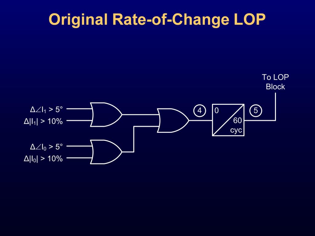
7 This slide shows a traditional LOP logic diagram in an SEL-321 Phase and Ground Distance Relay. This logic relies on traditional overvoltage and overcurrent elements to detect one, two, or three lost fuses. 7

8 This slide shows the breakdown of the logic required to assert traditional LOP. 8

9 This table shows a summary of recommendations and limitations for traditional LOP conditions. Keep the following in mind when determining set points for traditional LOP voltage elements: If you have a blown fuse on one PT, V 2 is 22.3 and V 1 is If you have blown fuses on two PTs, V 2 and V 1 are If 50M is not settable above the maximum load, then 59PL must be set below 22.3 V to prevent the three-phase LOP from operating during a two-blown-fuse condition. It is a good idea to set 59PL equal to 59QL so that anytime V 2 is greater than V 1, the Q element takes priority for an LOP declaration. The purpose of the V 1 voltage element is to determine a three-phase LOP. In addition, 59QL should be set greater than 10% V NOM to prevent false assertion during system unbalance. The advantage of setting 59PL higher is faster operation of three-phase LOP in situations where a slowly decaying V 1 causes a racing condition between LOP and a distance element. 9

10 Setting 50M for LOP is another consideration in traditional LOP. If 50M is set too high, LOP can falsely assert for a close-in three-phase fault. If 50M is set too low, LOP is blocked at all times. Therefore, 50M must be set above the maximum load. 10
11 If you are dealing with a two-terminal line, choose the weakest source when evaluating guidelines 1 and 2 shown on this slide. Once we evaluate the guidelines, we can determine if traditional LOP will work for us. 11

12 Recall the following guidelines, which are from the previous slide: 1. Close-in three-phase fault is less than the maximum load. 2. Remote three-phase fault is greater than the maximum load. 12

13 This slide shows that 50M must be set above the maximum load. When there is plenty of pickup for a remote three-phase fault, 50M is the most reliable. It is also the most secure when 50M is above the maximum load with a margin. Blocking elements refer to elements that are blocked on assertion of LOP, such as 21 and 67 elements. If LOP has low security and high dependability, blocking elements have high security and low dependability. For example, if 50M is set close to the load, the LOP security is low. This gives blocking elements high security and low dependability. Elements that become nondirectional overcurrent upon LOP assertion directly follow the dependability and security of the LOP settings. A lower 50M setting is more likely to cause an LOP assertion, which makes directional elements become nondirectional elements. These elements are then more dependable but less secure. This slide also shows how adjusting the 59PL element affects the operation of various elements. A low-voltage setting is similar to a high-current setting in how it affects security and dependability. 13

14 Although 50M and 59PL must not assert for an LOP condition, it is still possible to use traditional LOP by overlapping 50M and 59PL operations as much as possible in the protected line segment. The more distance there is between F A and F B, the more secure the LOP logic will be. Fault resistance will affect the distance between F A and F B. 14
15 In the example system shown on this slide, the system voltage is 161 kv and the load is 285 A. The source impedance and line impedance are both 1 per unit (pu). Assume that 59PL stays equal to 14, which is about 0.2 pu. Place a bolted fault on the line, and find the point at which V relay is 0.2 pu. If I fault is greater than the maximum load, then traditional LOP can be used. The more overlap there is between 50M and 59PL, the more secure the LOP element. The red line represents the pu voltage present for faults along the line. The blue line represents the fault/maximum load. The pink line represents the logic status of 59PL when 59PL is greater than 14 V. The green line represents the logic status of 50M when the fault is greater than the maximum load. A bolted, close-in fault with no fault resistance is the most difficult fault to distinguish from LOP. 15
16 The more overlap there is between 50M and 59PL, the better the LOP overage. 16
17 With a very high-resistance fault, the LOP does not assert because the voltage element never drops out for any fault on the line. However, the question now becomes can the distance element still see a fault? 17

18 In the example on this slide, the fault levels are lower than the load levels, but the voltage is well above the set point. Therefore, LOP does not falsely assert. As fault resistance increases, the three-phase LOP logic becomes more secure. 18
.")
19 In the example shown on this slide, a bolted, three-phase fault between 0.2 and 0.25 pu asserts LOP, exposing a hole in the setting. This example is from the same system modeled in the previous slides but with a higher maximum load (300 A). Because the maximum load is higher, 50M must be set higher to allow LOP to properly operate. 19

20 In the example on this slide, SV1 equals!59v1!50p1, where 59V1 is 14 V and 50P1 is 1.5 A. The element is allowed to trip because the distance element is faster than LOP. However, the assertion of LOP logic is misleading for this fault. This example shows a fault placed in the hole described on the previous slide. For more information, see 2 Hole At 255.cev in the Event Files folder in the supplemental material. 20
 I fault = (100 / (1.73 KV)) 1 / (1.25 Z 1 S) If I fault is greater than the maximum load, traditional LOP can still be used. This is valid for source impedance ratios (SIRs) less than 4.")
21 Calculate I fault where V 1 equals 0.2 pu with 100 MVA base. Solve for the fault current at the point where V relay equals 0.2 pu using the following equations: I fault pu = 1 / (1.25 Z 1 S) I fault = (100 / (1.73 KV)) 1 / (1.25 Z 1 S) If I fault is greater than the maximum load, traditional LOP can still be used. This is valid for source impedance ratios (SIRs) less than 4. I fault is a bolted fault. This equation is valid for cases where a V 1 of 0.2 pu is on the line section being protected (SIRs of 4 or less). This equation also assumes that the overcurrent element operates faster than the distance element. For a 67 V nominal system, a V 1 of 2 pu is about 14 V of V 1. Because 14 V is the default setting for 59PL, calculate the fault current at that point on the system. If 50M can be set lower than the current at this point, overlap is guaranteed between 50M and 59PL. 21
22 Traditionally, 50M is set at 1.1 times the maximum load. Setting the 50M at 0.75 of I fault gives 1.33 times pu, which should get the 50M to operate faster than 1.4 cycles in the SEL-311 series relays. This happens to be close to the actual operate time of the distance element. 22

23 In the example shown on this slide, the maximum load is 238 A and the fault current at 0.2 pu voltage is 269 A (close-in fault is 448 A). The 50P1 element is set to 262 A. The 50P1 element picks up 0.25 cycles before M1P to ensure LOP does not falsely assert. A close-in fault can challenge the traditional LOP logic speed. As long as 50P1 asserts prior to M1P, the traditional LOP does not falsely block distance elements. For more information, see 3 Speed Test LOP 0.cev in the Event Files folder in the supplemental material. 23
.")
24 A fault detector for the distance elements must be set lower than remote faults on the end of the line to ensure proper operation. In some cases, the fault detector of the distance element must be set lower than the 50M element (in the overlapping scheme). With the fault detector of the distance element set lower than the 50M element, there can be racing conditions between the LOP logic and the distance element protection. If 50M can be set at two times the bolted, close-in fault, it operates faster than the distance elements for a SIR of 1 and above (such as in the SEL-311C Transmission Protection System). 24

25 In the example on this slide, a three-phase LOP condition is presented to an SEL-311C-1. The load and the maximum torque angle (MTA) for a bolted three-phase fault are separated by 50 degrees. SV1 represents the traditional LOP logic. In this example, the distance element picks up at the same time as an SV1 assertion. The advanced LOP asserts faster than the distance element and the traditional LOP logic. In this case, advanced LOP asserts 0.75 cycles before M1P and traditional LOP logic. For more information, see 4 LOP 40 Angle Load 2.cev in the Event Files folder in the supplemental material. 25

26 In the example on this slide, a three-phase LOP condition is presented to an SEL-311C-1. The load and the MTA for a bolted three-phase fault are separated by only 10 degrees. SV1 represents the traditional LOP logic. In this example, the distance element picks up prior to SV1 assertion. The advanced LOP asserts faster than the distance element and the traditional LOP logic. In this case, advanced LOP asserts 0.5 cycles before M1P and 0.75 cycles faster than traditional LOP. The distance element operates faster during an LOP condition for a higher load and load angle (power factor) close to the MTA of the line. For more information, see 5 LOP 80 Angle Load 2.cev in the Event Files folder in the supplemental material. 26

27 With aggressive load encroachment settings, distance elements can be slowed during an LOP condition. The example on this slide has the load encroachment set at 65 degrees, with the initial load at 40 degrees. This reduces the resistive coverage of the distance element drastically but allows fast operation for bolted faults and security for an LOP condition. Traditional LOP benefits from the use of load encroachment. For more information, see 6 LOP 40 Angle With LE 3.cev in the Event Files folder in the supplemental material. 27

28 The yellow shaded area in the figure on this slide shows the area removed from the coverage of a mho element to ensure that traditional LOP operates properly by using load encroachment. 28

29 This slide shows the difference in resistance coverage for a 20 ohm fault down the line with load encroachment turned on (green line) and turned off (blue line). At 0.2 pu from the source, the load encroachment blocks the distance element from operating. With load encroachment turned on, traditional LOP is secure, but resistance coverage is limited for three-phase faults. This example assumes that the source and the line are of equal impedance. 29

30 When the speed of LOP is the same as the protection elements, fault detectors are employed. For close-in faults (0 V), 59P cannot be used; 50M must be used. The more pickup there is for a close-in fault, the faster 50M is. The close-in fault will have a racing condition between 50M and the 21 element, especially if 50M is set close to a fault value. Basically, a fault detector or load encroachment is needed to block or delay the distance elements long enough for LOP logic to operate. In legacy relays, torque-based directional elements do not allow directional decisions with 0 V for polarizing. 30

31 In general, one- or two-phase logic does not affect sensitivity. However, it must be delayed to ride through transient events, such as pole scatter from closing a breaker. 31
 describes conditions where traditional LOP will not work. A slow decay in V 1 will also challenge traditional LOP logic.")
32 SEL Application Guide AG , Improvements to the Loss-of-Potential (LOP) Function in the SEL-321, by Jeff Roberts and Ralph Folkers (available at describes conditions where traditional LOP will not work. A slow decay in V 1 will also challenge traditional LOP logic. 32

33 In the example on this slide, traditional LOP failed to operate for a three-way, gangoperated switch that isolated the PT. As can be seen from the voltage waveforms, the gang-operated switch did not open each phase at the same time, and there was also some arcing. Because the 50P element was set below load (this was the major issue with this operation), the relay eventually tripped on a Zone 1 distance element. While this event shows over 14 V of V 2 for the first cycle, this condition must exist for 3 cycles for the relay to assert LOP. If the relay had been set with 50P above load, we would have relied on the three-phase LOP logic for this condition, which would have asserted at 3.75 cycles (V 1 = 13.8), just before the Zone 3 element asserted. This condition would have latched, and no misoperation would have occurred. Zone 3 is on a 60-cycle timer, but Zone 1 is an instantaneous trip. A Zone 1 trip would have been prevented with a proper 50P1 setting. In this example, CTR is 160 and PTR is 1,400. Nominal phase-to-ground voltage is 93.8 kv (161 kv phase-to-phase voltage). This event shows that some system LOP conditions do not provide a steep drop in V 1. The traditional LOP is not nearly as secure as the advanced LOP would be for this scenario. The advanced LOP would have asserted when VA went to 0, which looks to have happened prior to this event. It would be difficult to guarantee traditional LOP would have stopped Zone 3 from asserting. For more information, see 7 Traditional LOP Event 1.TXT in the Event Files folder in the supplemental material. 33

34 This slide shows an unfiltered event report. This is another example of an LOP condition that is very difficult to detect with traditional LOP. In this example, VB voltage is very unstable and eventually leads to a Zone 1 misoperation. V 1 is well above 14 V, so three-phase LOP cannot assert. V 2, as shown on the next slide, fluctuates and prevents the 3-cycle timer from picking up on one- or two-blown fuse logic. For more information, see 8 Traditional LOP Event 2.TXT in the Event Files folder in the supplemental material. 34

35 The first 1.75 cycles of the event shown on this slide are when the Adaptive Multichannel Source (AMS) first starts, so ignore the very beginning of this event. Because the filtered event was not retrieved from the relay, the event was played back in a new SEL-311C-1. The filtered event was then retrieved. In this event, SV2 is the traditional LOP one- or two-blown fuse logic. Notice that SV2 asserts, but it does not time out until the breaker has opened (SV2T). The only way to prevent this misoperation with traditional LOP is to use a fault detector. Notice that the advanced LOP (LOP Relay Word bit) asserts. It only deasserts after the breaker has been opened (change in current). The interesting item to note here is that the new SEL-311C contains delta detection logic. In this event, M1P would not have operated because there was no change in current. Traditional LOP may not have latched in, but it was not required to restrain M1P from asserting in the original event. For more information, see 9 Traditional LOP Event 2 Playback.cev in the Event Files folder in the supplemental material. 35

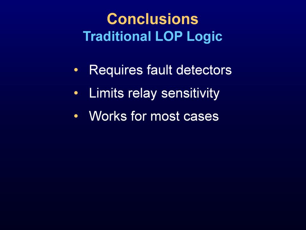
36 Ultimately, the speed of traditional LOP means fault detectors or load encroachment must be used to ensure security. The mho element is the fastest for the following: Weak systems High loads Low power factor Load encroachment and fault detectors sacrifice the sensitivity of mho elements. 36

37 Fault detectors and load encroachment may not need to be used on relays with delta current supervision. The delta detection supervision inherently restrains operation of the Zone 1 element for no change in current. 37

38 In addition to the challenges of traditional LOP, relay design is increasing the speed and sensitivity of elements. The negative-sequence element can operate on a 0 V condition. 38

39 As time has progressed, relays have become faster at detecting faults. 39

40 When V 2 has a 0 value, the Z 2 element declares forward using default settings. Traditional torque-based elements are disabled for a 0 V condition. 40

41 Initial rate-of-change LOP looks at the rate of change for V 1, I 1, and I 0. If V 1 decreases without a change of I 1 or I 0, LOP is declared. I 0 must be used for times when there are zero-sequence-only sources. 41

42 Only a 10 percent change in voltage is required to assert LOP when there is no change in current. This makes the element very fast for LOP detection. Relay sensitivity is not sacrificed. Current blocking is far superior in advanced LOP logic than in traditional LOP logic. If the fault current is 0.5 A secondary or greater than the maximum load or the fault angle is 5 degrees or more than the load angle, the logic blocks LOP regardless of the voltage drop. 42

43 As shown on this slide, an 8-sample-per-cycle relay samples positive-sequence current. The k value is the present sample; k 1 is from 1 cycle ago. If the magnitude difference is greater that 5% I NOM or the angle difference is greater than 5 degrees, LOP logic is blocked regardless of what happens to the positive-sequence voltage. This provides much greater sensitivity than standard LOP logic. 43

44 This slide shows the response of the primary relay, the backup relay, and the relay with improved LOP logic. This is also a real LOP condition encountered in the field. The following was taken from the technical paper Lessons Learned Analyzing Transmission Faults by David Costello (available at In the primary relay, an LOP is detected when negative-sequence voltage (V 2 ) is greater than 14 V secondary and negative-sequence current (3I 2 ) is less than 0.5 A secondary [9]. In the backup relay, an LOP is detected when zero-sequence voltage (V 0 ) is greater than 14 V secondary and zero-sequence current (I 0 ) is less than A secondary [10]. Once asserted, LOP blocks distance and directional elements that rely on healthy voltage signals. This event emphasizes that early LOP logic was designed to protect distance elements from misoperating for system faults that occurred some time after an initial LOP condition was detected. Overcurrent fault detectors set above load were used to prevent distance element misoperation when the LOP condition first occurred. In this event, the fault detector (50L) was picked up during balanced load flow. Ideally, fault detectors should be set above the expected load currents and below the minimum fault levels to ensure correct distance relay operation. Newer relays have LOP logic that operates based on the V 1 rate of change versus the rate of change of currents. The new logic operates in less than 0.5 cycles, so distance element security is less dependent on the fault detector settings. In Fig. 21 [shown on this slide], the response of the original relays are shown with that of a relay with improved LOP logic. The new relay LOP logic operates more than 1 cycle before any distance elements assert, ensuring this misoperation will not happen again. For more information, see 10 LOP Speed Comparison in the Event Files folder in the supplemental material. 44
 LOP that does not seal-in LOP (logic point 2).")
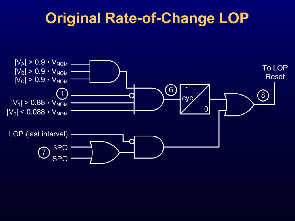
45 In addition to the heart of the advanced LOP logic, which is the rate of change of V 1 and I 1, there are some other items to note, which include the following: The breaker must be closed!3po. For a very light load, a breaker status contact is required. It is possible to have a temporary (transient) LOP that does not seal-in LOP (logic point 2). The major concern here is that a no-load breaker with line-side PTs will assert LOP until 3PO asserts (on the action of opening a breaker). To prevent a latch in, a 60 cycle pickup timer is used for LOP latching. There is a 60-cycle dropout timer that blocks an LOP assertion for 60 cycles after any change in I 1 or I 0. A breaker opening with light load may detect a ΔI 1 and a rapid V 1 decrease. Detecting the I 1 and blocking for 60 cycles ensures that LOP does not assert for the opening of a breaker with line-side PTs. This also blocks LOP assertion for 1 second anytime the breaker with line-side PTs is closed in to a bolted three-phase fault. There is reset logic to automatically remove the LOP condition. This logic is not designed to detect an LOP condition when the breaker is open. 45
46 46
47 47
48 Over time, advanced LOP has been improved to cover more cases. The challenges associated with advanced LOP logic include the following: Closing in to an LOP condition was not originally handled by advanced LOP logic. We will highlight the new logic to cover this case in the following slides. Bus PTs can provide unique challenges to advanced LOP logic. We will talk about two cases later in this presentation. Timing has been improved to add more security and dependability to the scheme. 48
 Conditions in the SEL-321, SEL-421, and SEL-311 Series Relays, by Greg Hataway (available at")
49 Traditional LOP detects blown fuses on a breaker closing. SEL Application Guide AG , Recommended Ways to Detect Loss-of-Potential (LOP) Conditions in the SEL-321, SEL-421, and SEL-311 Series Relays, by Greg Hataway (available at covers logic to detect LOP conditions on breaker open and close conditions while using advanced LOP logic. 49

50 The logic shown on this slide is used for line-side PTs. Breaker closing logic was originally active for 20 cycles after the breaker closed. V 1 must be greater than 10 V, so this logic does not detect all three-phase PTs blown on a breaker close. If the V 2 /V 1 ratio is greater than 0.15 and the currents are balanced, the logic asserts an LOP condition after 2 cycles. The 2-cycle time delay prevents a misoperation during pole scatter from a breaker close. I 0 /I 1 and I 2 /I 1 must be less than 0.15 to allow an LOP assertion. Another requirement not shown on this slide is that some amount of I 1 must be present for the relay to block an LOP assertion. A purely zero-sequence source does not block this logic. Also, closing the breaker into no load with an LOP condition does not assert LOP. 50

51 How did we get an LOP condition in the first place? See the original fault in 11 Breaker Closing on LOP.CEV in the Event Files folder in the supplemental material. It appears that the LOP condition occurred during a fault. In the example shown on this slide, the relay is applied to a distribution load. It takes the LOP logic 13.5 cycles to assert. This is because it takes a long time for the inrush condition presented to the relay to subside. In this case, the I 0 /I 1 ratio subsided 13.5 cycles after the breaker closing, while the I 2 /I 1 ratio subsided about 10 cycles after closing. Notice that the LOP dropped out after the breaker had been closed for 20 cycles. This logic was not sealed in. Because this is a distribution feeder, it is possible that an LOP would not lead to a misoperation. Speed is not extremely crucial here, but latching is needed to prevent subsequent misoperations if directional elements are being used. Traditional logic would have performed the following actions: Picked up about 34 cycles after the breaker closed, with 50Q equal to A. Picked up about 4.5 cycles after the breaker closed, with 50Q equal to 0.5 A. There are two considerations with this logic: What is the fastest, yet secure, ratio to use? A low ratio allows very fast LOP blocking during a fault, but it offers slow LOP assertion during a breaker close condition. How long should we keep this logic on? This event occurred with an SEL-421 Protection, Automation, and Control System. The new SEL-421 close-in logic is active for 70 cycles, which would seal in the LOP for this breaker closing event. For more information, see 11 Breaker Closing on LOP.CEV. 51

52 An I ratio of 0.5 is the lowest we would typically expect for a phase-to-phase-to-ground fault for I 2 / I 1 and I 0 / I 1. An I 2 / I 1 of 0.15, which is implemented in the relay, is very conservative. The following equations are used to help calculate the ratio: I 2 = I 1 (Z 0 / (Z 0 + X 2 )) I 2 / I 1 = Z 0 / (Z 0 + Z 2 ) Assume I 2 / I 1 is 0.15, and solve for Z 2 in terms of Z 0 using 5.67 Z 0 = Z 2. Therefore, Z 2 must be 5.67 times larger than Z 0 for a phase-to-phase-to-ground fault to falsely assert LOP. The advantage of this low ratio setting is that it blocks LOP faster for a legitimate fault. 52

53 Breaker closing logic is a great addition to the original advanced LOP logic. However, there are still some limitations to be aware of, such as those listed on this slide. On another note, if an LOP condition occurs during a fault, the closing logic is likely the only way to catch the LOP condition. 53

54 In the figure on this slide, the original advanced LOP logic could have an issue. If there is a fault on Bus 1 and the relay gets its polarizing voltage from the PT on Bus 1, LOP does not assert because fault current is present (this would be a close-in reverse fault for the line protection). When the bus is cleared, the voltage goes to zero before switching to the new bus voltage source. If load is still fed via Breaker 2, then there is a potential for misoperation. 54

55 The busbar PT logic shown on this slide is operating in parallel with the original advanced LOP logic. When the busbar PT is enabled, the breaker closing LOP is disabled. Busbar PT logic should be used when there are bus-side PTs. However, it is important to note that there are some limitations with this logic. For example, the ΔI check stays asserted for 2 cycles after a change in current. Therefore, when the bus fault in the previous example is declared (the line relay goes from a reverse fault to a load condition), LOP is blocked for 2 cycles. Therefore, there will be a 2-cycle hole in LOP detection. If the transfer switch is slower than 2 cycles, the relay will have no voltage present with load for this 2-cycle window. However, the relay uses memory polarization, maintains directional stability, and restrains from operation. Once the healthy PT is switched over, there is a 10-cycle delay for drop out of LOP (reset LOP time). For a very short amount of time after getting healthy voltage, the protection is still disabled. The logic asserts LOP anytime the bus PT goes dead. A bus differential that clears the bus asserts LOP. If the throw-over switch is faster than 2 cycles after the fault clears, there is the possibility of a transient condition in which the distance element could falsely assert prior to the assertion of LOP. A three-phase fault that produces a V 1 less than 10 V can produce a false LOP assertion after 2 cycles (dropout time of ΔI check). However, it is likely that the three-phase fault with this much voltage drop would be a Zone 1 fault and call for a trip prior to the LOP assertion. If a time-delay element is used, a false LOP assertion can occur that could block distance elements. 55
 are paralleled on Breaker A and the transformer. The PT is located on the bus.")
56 In the example shown on this slide, Bus 2 has a phase-to-ground fault, which is fed from all three lines. The relay in question protects the leftmost line. Current transformers (CTs) are paralleled on Breaker A and the transformer. The PT is located on the bus. When the Phase A-to-ground fault occurs, the magnitude change of I 1 and I 0 is large enough to block LOP for 60 cycles. The bus differential relay trips all three breakers. Once all three breakers are tripped, the voltage seen by the relay goes to zero. However, the transformer on the left is still fed remotely and the relay sees this current. Because LOP is blocked for 60 cycles, it is only a matter of time before this no-voltage and load-current scenario trips a distance element. 56

57 This slide shows the unfiltered event report with an odd decay in the unfaulted phase voltages. For more information, see 12 Unfiltered Bus PT.TXT in the Event Files folder in the supplemental material. 57

58 At the time of the trip, V1Mag was 17.3 V secondary and V2Mag was 14 V secondary. Traditional LOP would not have operated correctly for this event even if fault detectors could be set using the traditional 59V1 setting. The slow decay in V 1 was too slow for three-phase LOP to assert prior to distance element operation. The one- or two-blown fuse logic would not have enough time to assert because the pickup timer for that logic is 3 cycles. We only have about cycles, between I 2 being low enough and V 2 being high enough, to trigger the unbalance LOP logic. Busbar PT logic would not have worked for this event because V 1 at the time of the trip was greater than 10 V. The original advanced LOP was being used when this relay was in service. At 5 cycles, the bus was cleared and the voltage for the bus PT approached zero. This operation happened about 8 cycles after the initiation of the fault. Based on the voltage and current clearing, it appears Breaker A tripped first (isolating this relay from the bus), but the other breakers cleared slower (the bus voltage is held up for about 1.5 cycles after the local currents are reduced). The challenge in this event is that load currents are present while fault voltages are also present. The original advanced LOP logic blocked LOP assertion for 60 cycles after a change in current. The latest version only blocks LOP assertion for 2 cycles after a change in current and allows the LOP to better block for an LOP condition after a fault. However, this improved time would still not pick up LOP prior to the distance element assertion. The only way to block distance elements in this case is to use fault detectors. Be mindful of the bus arrangements used. For more information, see 13 Filtered Bus PT.TXT in the Event Files folder in the supplemental material. 58
59 As described on the previous slide, fault detectors should be set in certain applications to secure the distance elements when load can persist after a bus fault. There are a few possibilities of LOP operation during a bus fault in a breaker-and-a-half scheme using bus PT logic, including the following: Three-phase fault 0 V on the bus. LOP asserts after 2 cycles. After the bus clears, the PT can be switched to a healthy source without concern. LOP remains asserted for 10 cycles in the relays. This is the LOP reset time, which in this case directly affects how long the protection is either blocked or nondirectional after a bus fault. One- or two-phase fault. At the inception of the fault, LOP is blocked for 2 cycles. If the local breaker opens first (transition from fault current to load current), LOP does not assert until 2 cycles after the local breaker opens. If the local breaker opens last, voltage and current change at the same time and LOP is blocked for 2 cycles. 59
. In these cases, we want to unblock LOP as fast as possible. ΔI now blocks LOP for 2 cycles.")
60 The improvements listed on this slide secure LOP. ΔI previously blocked LOP for 60 cycles. Previous events show the value of unblocking LOP quickly. There can be a change in current due to the clearing of a fault, but the load remains (bus PTs). In these cases, we want to unblock LOP as fast as possible. ΔI now blocks LOP for 2 cycles. Previously, LOP had to exist for 60 cycles before it was latched in. One concern for latching the LOP was the breaker opening on no load with line-side PTs in which the 52A contact was slower than the voltage decay. It is possible for a transient LOP assertion in this case, but a timer of 60 cycles is not needed. Now LOP only needs to exist for 15 cycles to latch in. 60

61 As shown on this slide, a Phase-A-to-ground fault occurs on Line B. This line is using an SEL-421 with CTs connected on the 3575 breaker and high-side transformer CTs. On the following slide, we will see how the advanced LOP responds to a zero-sequence-only source. 61

62 In the event shown on this slide, the local breaker recloses at 4 cycles. At this instant, breaker close LOP is enabled for 20 cycles. At 14 cycles, the remote end closes in to the fault. The transformer becomes a zero-sequence-only source for this fault, but LOP is asserted because V 2 / V 1 is met and there is no I 1 present to block LOP from asserting. Therefore, LOP falsely asserts in this example. In this case, traditional LOP also falsely asserts unless a zero-sequence source was used to block LOP assertion. In bus arrangements like this, neither LOP logic would work as expected. Take care in determining LOP conditions. For more information, see 14 LOP With Zero-Sequence Source.txt in the Event Files folder in the supplemental material. 62
63 63
64 64

65 Take care in unique bus arrangements to evaluate LOP operation. 65

66 Use open-breaker LOP to detect LOP conditions when the breaker is open. Use advanced LOP when the breaker is closed. See SEL Application Guide AG for more information. 66

67 67
System Protection and Control Subcommittee
 Power Plant and Transmission System Protection Coordination GSU Phase Overcurrent (51T), GSU Ground Overcurrent (51TG), and Breaker Failure (50BF) Protection System Protection and Control Subcommittee
Bus Protection Application Challenges
 Bus Protection Application Challenges KN Dinesh Babu - Megger JC Theron, Lubomir Sevov GE Grid Solutions 2017 Texas A&M Protective Relay Conference Content Introduction Application Challenges Increase
SEL-487B. A Powerful Solution for Busbar Differential Protection. Bus Differential and Breaker Failure Relay
 Bus Differential and Breaker Failure Relay A Powerful Solution for Busbar Differential Protection Features and Benefits Select the for the differential protection of busbar systems with up to 18 terminals.
Identify and understand the operation of common bus. After this presentation you will be able to: Identify common bus arrangements
 Introduction to Bus Protection By Matt Horvath, P.E. November 6, 2018 Electrical Buses Physical and Electrical Junction A bus is a critical element of a power system, as it is the point of convergence
BREAKER FAILURE PROTECTION
 0 th Annual HANDS-ON RELAY SCHOOL March 11-15, 201 REAKER FAILURE PROTECTION brent.c@relayapplication.com OUTLINE Protection System Failures and reaker Failures Protection versus Relaying Relay Schemes
Verification of Utility Requirements on Modern Numerical Busbar Protection by Dynamic Simulation
 111 Verification of Utility Requirements on Modern Numerical Busbar Protection by Dynamic Simulation Z. Gajić (ABB, Sweden) JP Wang / PW Gong / YS Xu (ABB China) ZX Zhou (CERPI, China) Summary Power utilities
Approval...6. Current Revision...7. Introduction... 8 About PJM Manuals... 8 About This Manual... 8 Using This Manual...9
 PJM Manual 07: PJM Protection Standards Revision: 3 Effective Date: May 24, 2018 Prepared by System Planning Division Transmission Planning Department PJM 2018 Table of Contents Table of Contents Approval...6
Bus Differential and Breaker Failure Relay. Advanced bus protection with built-in breaker failure detection
 SEL-487B Bus Differential and Breaker Failure Relay Advanced bus protection with built-in breaker failure detection Protect busbars with up to 21 terminals using high-speed, low-impedance bus differential
Application of Undervoltage Protection to Critical Motors
 Application of Undervoltage Protection to Critical Motors Matt Proctor GE Grid Solutions 2018 Texas A&M Protective Relaying Conference Agenda Undervoltage Scenarios (Transient, Sag & Complete Loss) Motor
Bus Differential and Breaker Failure Relay. Advanced bus protection with built-in breaker failure detection
 SEL-487B Bus Differential and Breaker Failure Relay Advanced bus protection with built-in breaker failure detection Protect busbars with up to 21 terminals using high-speed, low-impedance bus differential
F6150. Power System Simulator For Testing Protection Relays and Schemes.
 F6TesT Visual protection testing software for f6000 power system simulators The ultimate software for the automated testing of individual relays and complete protection schemes F6TesT software offers the
Sensitive and Selective Ground-Fault Protection in Ungrounded MV Networks Using the DPU-2000R with the Directional-Sensitive-Earth Fault Feature
 ABB Application Note Substation Automation and Protection Division DPU2000R AN-80D-01 Sensitive and Selective Ground-Fault Protection in Ungrounded MV Networks Using the DPU-2000R with the Directional-Sensitive-Earth
UR Universal Relay Series
 GE Digital Energy UR Universal Relay Series Revision 3.50 Release Notes GE ublication Number: GER-4432 Copyright 2009 GE Multilin Overview Summary GE Multilin issues the UR 3.50 release that introduces
SPECIAL CONSIDERATION OF FEEDER PROTECTION FOR BREAKER-AND-A-HALF CONFIGURA- TIONS. G. Steynberg
 SPECIAL CONSIDERATION OF FEEDER PROTECTION FOR BREAKER-AND-A-HALF CONFIGURA- TIONS G. Steynberg Siemens AG; Energy Sector, Energy Automation, Nuremberg 1. INTRODUCTION The breaker-and-a-half configuration
PROTECTION, AUTOMATION & CONTROL
 PROTECTION, AUTOMATION & CONTROL 1. DTIVA The members of the DTIVA product line are configured to protect and control the elements of not solidly grounded radial networks. Here the application of Petersen
IMPROVING POWER SYSTEM RELIABILITY USING MULTIFUNCTION PROTECTIVE RELAYS
 IMPROVING POWER SYSTEM RELIABILITY USING MULTIFUNCTION PROTECTIVE RELAYS Armando Guzmán Schweitzer Engineering Laboratories, Inc. Pullman, WA 99163 A reliable power system maintains frequency and voltage
UR Universal Relay Series
 GE Digital Energy UR Universal Relay Series Revision 4.43 Release Notes GE Publication Number: GER-4380Rev1 Copyright 2010 GE Multilin Summary Overview GE Multilin issues the UR 4.43 release that introduces
Lessons Learned in Static VAR Compensator Protection
 Lessons Learned in Static VAR Compensator Protection Aaron Findley, Mychal Hoffman POWER Engineers, Inc. Dan Sullivan, Jan Paramalingam Mitsubishi Electric Power Product Inc. Presented by: Aaron Findley
Windfarm System Protection Using Peer-to-Peer Communications
 Windfarm System Protection Using Peer-to-Peer Communications Michael Reichard GE Energy John Garrity GE Corporate 1. Introduction Windfarm electrical systems present some unique challenges for protection.
Maximizing protection coordination with self-healing technology
 Supersedes December 2011 Daniel P. Roth, Distribution Automation Technical Manager, Eaton s Cooper Power Systems Abstract Much of the Smart Grid initiative includes the installation of new recloser and
1S20. Arc Fault Monitor Relay. Features. Introduction. ARC Fault Protection
 Technical Bulletin Arc Fault Monitor Relay Features Compact, economic design Simple panel mounting for retrofit applications Two or three arc sensor inputs Two high speed tripping duty arc sense output
Loop Automation. Technical Manual for the ADVC Controller Range
 Loop Automation Technical Manual for the ADVC Controller Range Contents List of Figures 5 List of Tables 7 Acronyms 7 Symbols 7 Introduction 8 About this Manual 8 ADVC Controller Firmware Version 9 WSOS
Release 5.83 of the Universal Relay (UR) series introduces improvements for general and protection functions. Highlights of version 5.
 series introduces improvements for general and protection functions. Highlights of version 5.") GE Digital Energy UR Series Revision 5.83 Release Notes GE Publication Number: GER-4648A Copyright 2015 GE Multilin Inc. Overview Summary Release 5.83 of the Universal Relay (UR) series introduces improvements
GE Digital Energy UR Series Revision 5.83 Release Notes GE Publication Number: GER-4648A Copyright 2015 GE Multilin Inc. Overview Summary Release 5.83 of the Universal Relay (UR) series introduces improvements
Redundant Bus Protection Using High-Impedance Differential Relays. Josh LaBlanc
 Redundant Bus Protection Using High-Impedance Differential Relays Josh LaBlanc Purpose Discuss the configuration of the bus under study, and touch on the needs for redundant protection on the bus. Briefly
An Artificial Intelligence Based Approach for Bus Bar Differential Protection Faults Analysis in Distribution Systems
 An Artificial Intelligence Based Approach for Bus Bar Differential Protection Faults Analysis in Distribution Systems By Eng. Sameh Moustafa Mohamed Abd Elgowad Elbana A thesis submitted to The Faculty
BE1-50/51M TIME OVERCURRENT RELAY ADVANTAGES
 BE1-50/51M TIME OVERCURRENT RELAY The BE1-50/51M Time Overcurrent Relay provides economical overload and fault protection for generators, transformers, lines and motors. ADVANTAGES Self powered from 50/60Hz
Power systems 5: Protection
 Power systems 5: Protection Introduction In this series of articles, we will be looking at each of the main stages of the electrical power system in turn. As you will recall from our Introduction to Electrical
SEL Event Report Frequently Asked Questions
 Event Analysis Introduction Session SEL Event Report Frequently Asked Questions 1. How is an event report generated by an SEL relay? A. Relay trip from trip equation (TR). Example 1: TR := 49T OR 50P1T
This webinar brought to you by the Relion product family Advanced protection and control IEDs from ABB
 This webinar brought to you by the Relion product family Advanced protection and control IEDs from ABB Relion. Thinking beyond the box. Designed to seamlessly consolidate functions, Relion relays are smarter,
Advanced Line Differential Protection, Automation, and Control System. Combine subcycle line protection with traveling-wave fault locating
 Advanced Line Differential Protection, Automation, and Control System Combine subcycle line protection with traveling-wave fault locating Subcycle differential and distance protection minimizes damage
ELG4125: System Protection
 ELG4125: System Protection System Protection Any power system is prone to 'faults', (also called short-circuits), which occur mostly as a result of insulation failure and sometimes due to external causes.
SEL-221F/121F Distance Relay
 SEL-221F/121F Distance Relay SEL-221F and SEL-121F Phase and Ground Distance Relay, Directional Ground Relay, Synchronism Checking Relay, Reclosing Relay, Fault Locator Data Sheet Three zones of phase
USE CASE 13 ADAPTIVE TRANSMISSION LINE PROTECTION
 H USE CASE 13 ADAPTIVE TRANSMISSION LINE PROTECTION Use Case Title Adaptive Transmission Line Protection Use Case Summary The requirements for improvement in the performance of protection relays under
Overcurrent and Arc Protection by Reyrolle Alexander Erokhin. 21, 2017 I Berlin
 Overcurrent and Arc Protection by Reyrolle Alexander Erokhin VAR Partner Day September 20-21, 21, 2017 I Berlin Reyrolle Product Range by SIEMENS Challenges We Meet for our Customers Easy-to-use protection
Substation Automation Products. Line differential protection RED670 Relion 670 series
 Substation Automation Products Line differential protection RED670 Relion 670 series For maximum reliability of your power system The RED670 IED (Intelligent Electronic Device) is designed for protection,
Built for speed, security, and simplicity
 Time-Domain Line Protection Built for speed, security, and simplicity Traveling-wave-based and incremental-quantity-based line protection schemes as fast as ms with traditional pilot channels and over
ABB Inc. Substation Automation and Protection Division Coral Springs, FL Allentown, PA. Multi-Zoned Distance
 ABB ABB Inc. Substation Automation and Protection Division Coral Springs, FL Allentown, PA Descriptive Bulletin September 21 Multi-Zoned Distance Device umber:21/21, 21B, 21P/21P, 2, 27, /, BF, 1/1, Q/1Q,
AUTOMATED TESTING OF BUSBAR DIFFERENTIAL PROTECTION USING A SYSTEM-BASED APPROACH. Christopher Pritchard, Florian Fink
 AUTOMATED TESTING OF BUSBAR DIFFERENTIAL PROTECTION USING A SYSTEM-BASED APPROACH Christopher Pritchard, Florian Fink OMICRON electronics GmbH, Klaus, Austria; Christopher.Pritchard@omicronenergy.com ABSTRACT
Protection, Automation, and Control System. Combine subcycle line protection with complete substation bay control
 Protection, Automation, and Control System Combine subcycle line protection with complete substation bay control Subcycle distance protection minimizes damage and expensive repairs on transmission lines.
Bus Bar Protection Applications Seminar
 Bus Bar Protection Applications Seminar April 3, 2006 College Station TX ZONE 1 23 24 ZONE 2 1 2 11 12 13 22 ZONE 1 ZONE 2 23 24 1 2 3 21 22 Presentation Outline Introduction to Bus Bar Protection Bus
Short-Circuit Calculation Methods
 Short-Circuit Calculation Methods Oct 1, 2004 12:00 PM, By Massimo Mitolo, Ph.D., Chu & Gassman Consulting Engineers Ref.: http:// ecmweb.com/mag/electric_shortcircuit_calculation_methods/ The task may
FP6000. Type ID Units Writable Possible Values. Count. TCP Register
 FP6000 Category System ID 1032 Vendor Name 32 ASCII no-units 1064 Model Name 32 ASCII no-units 1096 Display Name 32 ASCII no-units 1128 Device Type 32 ASCII no-units 1605 Field Replaceable Unit 1 UINT16
Substation Automation Products. Line distance protection REL670/650 Relion 670 and 650 series
 Substation Automation Products Line distance protection REL670/650 Relion 670 and 650 series For maximum reliability of your power system REL670 and REL650 line distance protection IEDs (Intelligent Electronic
Applications of Automated Protective Relay Testing. Josh LaBlanc
 Applications of Automated Protective Relay Testing Josh LaBlanc First, automated protective relay testing. What is it? 2 Where can it be applied? Preventative Maintenance Testing The applications are endless
SEL-321 Data Sheet. Phase and Ground Distance Relay, Directional Overcurrent Relay, Fault Locator
 SEL-321 Data Sheet Phase and Ground Distance Relay, Directional Overcurrent Relay, Fault Locator Four Zones of Phase and Ground Distance Protection: Mho characteristic phase elements Mho and quadrilateral
Busbar protection REB 670
 Gunnar Stranne Busbar protection REB 670 Rio de Janeiro April 23-25, 2006 ABB Power Technologies AB 2 3 4 REB 500 is enabled for use with IEC61850 communication Benefits of REB 670 outstanding features
The Digital Substation: resilient and Cyber Secure Protection and Control
 The Digital Substation: resilient and Cyber Secure Protection and Control Sakis Meliopoulos Georgia Institute of Technology, Atlanta, Georgia USA PSERC Webinar, November 20, 2018 1 Presentation Outline
PRC Coordination of Protection Systems for Performance During Faults
 PRC-027-1 Coordination of Protection Systems for Performance During Faults A. Introduction 1. Title: Coordination of Protection Systems for Performance During Faults 2. Number: PRC-027-1 3. Purpose: To
Windfarm System Protection Using Peer-to-Peer Communications
 Windfarm System Protection Using Peer-to-Peer Communications Michael Reichard GE Energy Dale Finney GE Multilin John Garrity, Sr GE Multilin 1. Introduction Windfarm electrical systems present some unique
SEL-587Z High-Impedance Differential and Overcurrent Relay
 SEL-587Z High-Impedance Differential and Overcurrent Relay Bus or Transformer Protection The SEL-587Z Relay is a flexible high-impedance differential relay that combines time-proven high-impedance analog
A Current Based, Communication Assisted High Speed Protection System to Limit Arc Energy. Patrick Robinson Altelec Engineering
 A Current Based, Communication Assisted High Speed Protection System to Limit Arc Energy Patrick Robinson Altelec Engineering Captured Arcing Fault Event Arc begins as phase A-C, 8ka peak, dies out then
FP5000. Refer to for the latest information on this constantly evolving product
 FP5000 Refer to www.eatonelectrical.com for the latest information on this constantly evolving product FP5000 Product Overview Microprocessor design combines protection, metering and control into a single
Implementing the protection and control of future DC Grids
 Implementing the protection and control of future DC Grids Hengxu Ha, Sankara Subramanian Innovation and Technology Department, SAS, Alstom Grid 1. The challenge of the DC Grid protection 1 High speed
2 ms arc-flash protection and feeder relay in one platform
 Feeder Protection Relay 2 ms arc-flash protection and feeder relay in one platform Combine light sensor inputs with high-speed overcurrent protection to achieve secure arc-flash protection in as fast as
Multifunction Relays and Protection Logic Processors in Distribution Substation Applications
 Multifunction s and Protection Logic Processors in Distribution Substation Applications David Sánchez Escobedo, Eliseo Alcázar Ramírez, Oscar A. Márquez Villanueva, and Héctor J. Altuve Ferrer Schweitzer
Power System Protection Laboratory Electric Power and Energy Engineering
 Experiment no. 5 Overcurrent Protection of Transmission Line Power System Protection Laboratory Electric Power and Energy Engineering Dr. Jamal Thalji Eng. Saddam Ratrout Eng. Mageda El-Moubarak Content
SPECIFIC INTERCONNECTION PROTECTION REQUIREMENTS... 5
 Central Hudson Gas & Electric Corporation (CHG&E) Interconnection Protection Requirements for Distributed Generators of Greater than 300 kva Connected in Parallel with the CHG&E Electrical Delivery System
REL512 Firmware Version 1.61 Addendum (03/27/03)
") REL512 Firmware Version 1.61 Addendum (03/27/03) Revisions The following revisions are added to firmware V 1.60 to provide firmware V 1.61 for all applications. These revisions are to be added (inserted)
REL512 Firmware Version 1.61 Addendum (03/27/03) Revisions The following revisions are added to firmware V 1.60 to provide firmware V 1.61 for all applications. These revisions are to be added (inserted)
THE INTEGRATED TESTING SOLUTION
 Test & Data Management Software TDMS protective relays energy meters transducers power quality CT-VT-PT transformers ground grid circuit breakers batteries surge arresters THE INTEGRATED TESTING SOLUTION
DTRV-EP. COMPLEX DIGITAL PROTECTION FOR 120 kv / MEDIUM VOLTAGE TRANSFORMERS. Application field
 DTRV-EP COMPLEX DIGITAL PROTECTION FOR 120 kv / MEDIUM VOLTAGE TRANSFORMERS Application field The DTRV type of complex transformer protection is designed to protect 120 kv / medium voltage transformers,
Single-Phase Testing of the SEL-487E Differential Element Without State Simulation
 Application Guide Volume IV AG010-09 Single-Phase Testing of the SEL-487E Differential Element Without State Simulation David Costello and Jason Young INTRODUCTION When testing a differential element,
Automated real-time simulator testing of protection relays
 Automated real-time simulator testing of protection relays by B S Rigby, School of Electrical, Electronic and Computer Engineering, University of KwaZulu-Natal This paper describes the results of a project
Distributed bus protection application in a platform for process bus deployment in the SMART SUBSTATION
 Jorge Cardenas, GE Digital Energy David McGinn, GE Digital Energy Michael Miller, GE Digital Energy Ilia Voloh, GE Digital Energy Richard Hunt, GE Digital Energy Distributed bus protection application
Feeder protection relay SPAA 121 C. Product Guide
 Issued: April 1999 Status: Updated Version: C/06.03.2006 Data subject to change without notice Features Two-phase low-set phase overcurrent unit with definite time or inverse time characteristic Two-phase
Integrating Monitoring and Diagnostic Equipment on Aging Transformers
 May 13-14, 2008 International Centre, Mississauga, Ontario April 2008 Volume 20, No. 3 Integrating Monitoring and Diagnostic Equipment on Aging Transformers Valuable information on maintaining critical
User Manual. AQ-F215 Simulator
 User Manual AQ-F215 Simulator Instruction manual AQ-F215 Simulator 2 (28) Revision 1.00 Date 16.5.2014 Changes N/A Revision 1.01 Date 13.3.2018 Changes Updated visual look Readability improvements Instruction
UR Universal Relay Series
 GE Consumer & Industrial UR Universal Relay Series Revision 5.40 Release otes GE Publication umber: GER-4109 Copyright 2007 GE Multilin Overview Summary GE Multilin issues the UR 5.40 release that introduces
Siprotec 7ST61 / 7ST63
 Siprotec / Numerical overhead contact line protection for AC traction power supply siemens.de/rail-electrification The numerical overhead contact line protection relay Siprotec / is a selective and quick
Introduction to Protection Basics
 Introduction to Protection Basics BRENT L. CARPER, P.E. Principal Engineer Presented at the 35th Annual Hands-On Relay School March 12-16, 2017 Agenda HRS schedule and logistics Tips for a great week Introduction
SEL-551/SEL-551C Overcurrent and Reclosing Relay
 SEL-551/SEL-551C Overcurrent and Reclosing Relay Major Features and Benefits Phase, ground, and negative-sequence overcurrent protection US and IEC time-overcurrent curves Multiple-shot reclosing relay
Numerical Protective and Management Relays
 Numerical Protective and Management Relays Presented at: The Institution of Engineers (India) Andaman and Nicobar State Centre Port Blair Dr. H. K. Verma Deputy Director and Professor of Electrical Engineering
p. 1 p. 9 p. 26 p. 56 p. 62 p. 68
 The Challenges and Opportunities Faced by Utilities using Modern Protection and Control Systems - Paper Unavailable Trends in Protection and Substation Automation Systems and Feed-backs from CIGRE Activities
Why is my AFCI tripping?
 www.garyklinka.com Page 1 of 21 Instructions: Fee $25 1. Print these pages. 2. Use the included information located on pages 12-20 to answer the 61 questions below. 3. Circle the correct answers and transfer
Application Notes on Generator Protection Schemes
 Application Notes on Generator Protection Schemes Single Line Diagram Examples 1. Introduction The application notes provide selected single line diagrams for the SIPROTEC 4 generator protection device
7SG1641 Ohmega Protection Relays Answers for energy
 Reyrolle Protection Devices 7SG1641 Ohmega 402-50 Protection Relays Answers for energy 7SG1641 Ohmega 402 50 Contents Contents 1 Description of Operation 2 Impedance Functions 3 Protection Schemes 4 Relay
High-speed transformer differential protection for up to five terminals
 Transformer Protection Relay High-speed transformer differential protection for up to five terminals Advanced differential protection and three restricted earth fault (REF) elements minimize damage and
Important Considerations in Testing and Commissioning Digital Relays
 Important Considerations in Testing and Commissioning Digital Relays Drew Welton, Beckwith Electric Co. Inc. Will Knapek, OMICRON electronics Corp. USA Justification Digital technology in protection relays
Reyrolle Protection Devices. 7SG117 Argus 7 Synchronising Relay. Answers for energy
 Reyrolle Protection Devices 7SG117 Argus 7 Synchronising Relay Answers for energy 7SG117 Argus 7 Synchronising Relay Fig 1. Independent check & system synchronising settings Adjustable slip frequency,
LOW VOLTAGE BLDC MOTOR CONTROLLER
 DESCRIPTION The D113-024D10/036D10/050D05 are members of a DSP based low voltage brushless DC motor controller family. The controllers are for controlling the brushless DC motor with or without Hall position
Landsnet-Icegrid. Requirements for protection and control systems. Principles for the Icelandic power transmission network.
 Landsnet-Icegrid Requirements for protection and control systems. Principles for the Icelandic power transmission network. Introduction.... 4 System requirements... 6 Validity:... 6 Requirements for protection:...
What s New in Version 14 of ASPEN OneLiner/ Power Flow
 What s New in Version 14 of ASPEN OneLiner/ Power Flow The following are the new features in version 14 of ASPEN OneLiner/Power Flow. 1. Sharper and more vivid graphics on Windows 10. 2. New command to
UR Universal Relay Series
 G Digital nergy UR Universal Relay Series Revision 5.24 Release otes G Publication umber: GR-4387rev1 Copyright 2010 G Multilin Summary Overview G Multilin issues the UR 5.24 release that introduces new
1. Project Description
 Page No: 1 of 16 1. Project Description 1.1 Introduction This document outlines protection, monitoring and control requirements for the shared network assets associated with establishment of Tarrone Terminal
Substation Automation Products. Transformer protection RET670/650 Relion 670 and 650 series
 Substation Automation Products Transformer protection RET670/650 Relion 670 and 650 series For reliable protection and control of all types of power transformers and reactors The RET670/650 IEDs (Intelligent
( ) Regional Reliability Standard ( ) Regional Criteria ( ) Policy (x) Guideline ( ) Report or other ( ) Charter M&VWG. Physical location: Web URL:
 Regional Reliability Standard ( ) Regional Criteria ( ) Policy (x) Guideline ( ) Report or other ( ) Charter M&VWG. Physical location: Web URL:") Document name Cross-Current Compensation Model Specification Category Document date June 18, 2015 Adopted/approved by ( ) Regional Reliability Standard ( ) Regional Criteria ( ) Policy (x) Guideline (
Document name Cross-Current Compensation Model Specification Category Document date June 18, 2015 Adopted/approved by ( ) Regional Reliability Standard ( ) Regional Criteria ( ) Policy (x) Guideline (
FP-5000 Series Multi-functional Microprocessor-based Feeder Protective Relay
 FP-5000 Series Multi-functional Microprocessor-based Feeder Protective Relay The power of fusion. 1874 1886 1893 1899 1906 1908 1911 1934 1962 1963 1976 1983 1990 1999 There s a certain energy at Eaton.
Utility Implements Communications- Assisted Special Protection and Control Schemes for Distribution Substations
 Utility Implements Communications- Assisted Special Protection and Control Schemes for Distribution Substations Michael. Duff City of College Station Payal Gupta, Dharmendra Prajapati, and Alex Langseth
SOUTHERN REGIONAL POWER COMMITTEE BENGALURU
 SOUTHERN REGIONAL POWER COMMITTEE BENGALURU Additional Agenda for the 80 th Meeting of Protection Coordination Sub-Committee of SRPC to be held on 20-21 December, 2018 1. Grid Occurrences Additional Grid
Type SDR reclosers plus controllers and type B-2 recloser bypass switch assembly usa.siemens.com/mediumvoltage
 Overhead solutions Type SDR reclosers plus controllers and type B-2 recloser bypass switch assembly usa.siemens.com/mediumvoltage Overhead switching products Brochure Your outdoor overhead distribution
DIGITAL RELAY OF PROTECTION AND AUTOMATION SERIES PC83 AND PC830
 DIGITAL RELAY OF PROTECTION AND AUTOMATION SERIES PC83 AND PC830 PC83 and PC830 series devices are designed to perform the relay protection functions and 6-154 kv networks automation, have different functionality
Flexible High-Speed Load Shedding Using a Crosspoint Switch
 Flexible High-Speed Load Shedding Using a Crosspoint Switch Will Allen and Tony Lee Schweitzer Engineering Laboratories, Inc. Published in Wide-Area Protection and Control Systems: A Collection of Technical
UR Universal Relay Series
 GE Digital Energy UR Universal Relay Series Revision 5.90 Release otes GE Publication umber: GER-4401 Copyright 2010 GE Multilin Summary Overview GE Multilin issues the UR 5.90 release that introduces
ASPEN Software - Introduction
 ASPEN Software - Introduction ASPEN is a very user-friendly software package that is capable of doing load-flow and shortcircuit studies, as well as relay application and coordination. Its simple graphical
Blackstart Hardware-in-the-loop Relay Testing Platform
 21, rue d Artois, F-75008 PARIS CIGRE US National Committee http : //www.cigre.org 2016 Grid of the Future Symposium Blackstart Hardware-in-the-loop Relay Testing Platform R. LIU R. SUN M. TANIA Washington
MiCOM P124 T&D. Self and Dual Powered Overcurrent Relays
 PROTECTION MiCOM P124 Self and Dual Powered Overcurrent Relays MiCOM P124 are numerical relays designed to offer complete overcurrent protection without requiring any external auxiliary supply. They can
Standard Development Timeline
 Standard Development Timeline This section is maintained by the drafting team during the development of the standard and will be removed when the standard becomes effective. Description of Current Draft
Redundant Bus Protection Using High-Impedance Differential Relays
 Redundant Bus Protection Using High-Impedance Relays Josh LaBlanc, Schweitzer Engineering Laboratories, Inc. (formerly of Minnesota Power) Michael J. Thompson, Schweitzer Engineering Laboratories, Inc.
AUGUST 2001 APPLICATION AND COMMISSIONING MANUAL MIT161 RELAY EASUN REYROLLE LIMITED
 AUGUST 2001 APPLICATION AND COMMISSIONING MANUAL MIT161 RELAY EASUN REYROLLE LIMITED 1 Issue No : 2nd Issue Date of Issue : 30.08.2001 Department : TP-CTS 2 SENSITIVE CURRENT PROTECTION PROTECTION HEALTHY
UR Plus Series. Revision 1.73 Release Notes. GE Digital Energy. Overview. GE Publication Number: GER Summary. Copyright 2013 GE Multilin Inc.
 G Digital nergy UR Plus Series Revision 1.73 Release Notes G Publication Number: GR-4372 Copyright 2013 G Multilin Inc. Overview Summary Release 1.73 of the UR Plus series introduces product-specific and