MOD-RFID125-BOX user's manual
|
|
|
- Kory Adams
- 6 years ago
- Views:
Transcription

 2011,")
1 MOD-RFID125-BOX user's manual All boards produced by Olimex are ROHS compliant Rev.C, February 2013 Copyright(c) 2011, OLIMEX Ltd, All rights reserved Page 1
2 DISCLAIMER 2013 Olimex Ltd. Olimex, logo and combinations thereof, are registered trademarks of Olimex Ltd. Other product names may be trademarks of others and the rights belong to their respective owners. The information in this document is provided in connection with Olimex products. No license, express or implied or otherwise, to any intellectual property right is granted by this document or in connection with the sale of Olimex products. Both the hardware and the software projects are kept private. It is possible that the pictures in this manual differ from the latest revision of the board. The product described in this document is subject to continuous development and improvements. All particulars of the product and its use contained in this document are given by OLIMEX in good faith. However all warranties implied or expressed including but not limited to implied warranties of merchantability or fitness for purpose are excluded. This document is intended only to assist the reader in the use of the product. OLIMEX Ltd. shall not be liable for any loss or damage arising from the use of any information in this document or any error or omission in such information or any incorrect use of the product. This evaluation board/kit is intended for use for engineering development, demonstration, or evaluation purposes only and is not considered by OLIMEX to be a finished end-product fit for general consumer use. Persons handling the product must have electronics training and observe good engineering practice standards. As such, the goods being provided are not intended to be complete in terms of required design-, marketing-, and/or manufacturingrelated protective considerations, including product safety and environmental measures typically found in end products that incorporate such semiconductor components or circuit boards. Olimex currently deals with a variety of customers for products, and therefore our arrangement with the user is not exclusive. Olimex assumes no liability for applications assistance, customer product design, software performance, or infringement of patents or services described herein. THERE IS NO WARRANTY FOR THE DESIGN MATERIALS AND THE COMPONENTS USED TO CREATE MOD-RFID125-BOX. THEY ARE CONSIDERED SUITABLE ONLY FOR MOD-RFID125-BOX. Page 2
3 INTRODUCTION: FEATURES: MOD-RFID125-BOX is an RFID station, able to read Manchester-encoded 64-bit EM4102 tags with 64 periods of carrier frequency per data bit. All the complexity of RFID tag detection, verification and decoding are handled by MOD-RFID125-BOX. After it strips the header and the checksums user is given the 40-bit ID of the transponder tag. MOD-RFID125-BOX supports three distinctive modes of operation, easily switched by a single button press. It can emulate USB HID keyboard and input the read TAG ID directly to any Windows application, including the venerable Notepad. Or it can emulate USB CDC serial port for easy access from custom user applications using standard code for COM port access. The third option allows access from any standard 5V UART, allowing easy integration with existing microcontroller applications. - Supports Manchester-encoded 64-bit EM4102 RFID tags with 64 periods of carrier frequency per data bit; - Base RFID frequency 125kHz; - USB port connection to PC; - Standard 5V UART 9600, 8N1 connection to user microcontroller boards; - Three modes of operation, easily changed by pressing the button; - USB HID keyboard emulation mode; - USB CDC serial port emulation mode; - UART connection mode; - UEXT connector; - Simple command-line interface in USB CDC and UART modes for configuration and data acquisition; - Two LEDs indicating device status and tag presence; - Support for continuous and periodic RF scanning to better suit user power requirements; - Ships with default mode USB HID and default configuration: continuous read, scan always, one report per second, LEDs activated; ELECTROSTATIC WARNING: REQUIREMENTS: The MOD-RFID125-BOX board is shipped in protective anti-static packaging. The board must not be subject to high electrostatic potentials. General practice for working with static sensitive devices should be applied when working with this board. Cables: 1.8 meter USB A-B cable. Power: External 6-9V DC power supply (applicable in UART mode). Software: Page 3

4 SUPPORTED RFID TAGS: Software needed for USB HID keyboard mode: - Notepad or other text editor. Software needed for USB CDC and UART modes: - HyperTerminal or other terminal program. MOD-RFID125-BOX supports RFID transponder tags with the following characteristics: - Based on EM4102 chip; - 125kHZ carrier frequency; - 64-bit ROM, continuously transmitted; - 64 periods of carrier frequency per data bit; - Manchester encoding; UEXT CONNECTOR SCHEMATICS: If you have to connect to the UART note that the UART baud rate is UEXT pin Abbrev. description 1 NC Not Connected 2 GND Ground 3 RXD UART Receive Data (MOD-RFID125- BOX input) 4 TXD UART Transmit Data (MOD-RFID125- BOX output) 5 NC Not Connected 6 NC Not Connected 7 NC Not Connected 8 NC Not Connected 9 NC Not Connected 10 NC Not Connected POWER SUPPLY: Normally the device is supplied from USB. MOD-RFID125-BOX can be connected to external 6-9V DC power supply. This can relief the USB hub power supply when device is in USB HID or USB CDC mode. External power supply is mandatory for UART mode of operation. Page 4
.")
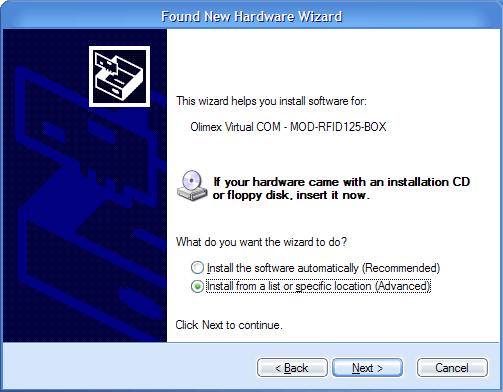
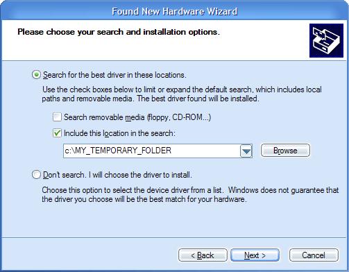
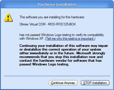
5 POWER SUPPLY CABLE CONNECTION Pin Connect to V DC 2 GND Note: If you want to use the board with external power supply, you have first to switch to UART mode when your board is connected to the USB (USB HID or USB CDC mode). LEDS: In normal mode the GREEN LED is on whenever the RF antenna circuit is active and scanning for RFID tags. The RED LED switches on whenever a valid RF TAG ID is being scanned and decoded successfully. The LEDs can be switched off to save power consumption. See the Command Line Interface section for more information. In boot loader mode the LEDs have other meaning. See the Firmware Upgrade section for more information. PC DRIVER INSTALLATION: Drivers for the USB HID mode are integrated in Windows XP/Vista. The driver for USB CDC mode is available from our website. Windows installation steps are the following: 1. Download and unzip the file MOD-RFID125-drivers.zip in a temporary directory. 2. Plug the programmer in the USB port. 3. Point the Device Wizard to the temporary directory. 4. Windows will complain that drivers are not signed. Click Continue. 5. Click finish. Screen shots of the steps are shown below: Page 5
6 Page 6

7 USB HID MODE: USB CDC MODE: Linux distributions normally include drivers both for USB HID and USB CDC classes. Depending on which driver is loaded in the kernel, user should look either for /dev/ttyacmn or /dev/ttyusbn where "n" is a number, assigned by the kernel to the plugged device. When device is connected via USB to a host PC it will represent itself as USB HID keyboard. When an RFID transponder is detected in the vicinity, the module will type the HEX-representation of the transponder ID. To use the device in this mode: 1. Open Notepad. 2. Plug in the device in the USB port of the PC. 3. Put an RFID tag in front of the device. The TAG ID will be entered in the currently opened text file. There is no need for OS driver because all major operating systems include USB HID drivers. NOTE: This mode does not allow configuration of device parameters. MOD- RFID125-BOX is shipped with default configuration for continuous read and one second repeat. If this must be changed then device must be switched to USB CDC mode and configured using the serial command line interface. In this mode the device represents itself as USB CDC virtual serial port. It provides a simple shell-like command line interface for configuring and interacting with the module. The device echoes back the typed characters and waits for Carriage Return (Enter) before processing the line input. See Command Line Interface for more information on the supported commands. Page 7
8 UART MODE: Any terminal software can be used to open the COM port, assigned by the OS, and type in commands. In this mode there is no need for USB connection. Instead the device must be connected via UEXT connector to a TTL-level UART of a microcontroller system of choice. It expects the peer to be configured with 9600 bps, 8bit character, no parity, 1 stop bit. The communication is otherwise the same as in USB CDC mode, but there is no need for USB. Again, all entered characters are echoed back. SWITCHING OPERATING MODES: The current mode of operation can be selected by pressing and holding the button of the device. After two seconds the LEDs will start to blink and will show the code for the next selected mode. When button is released, the device will reboot and enter the selected mode. Selected mode is remembered between power downs. The assigned codes are: LED Status Description Red Green Previous State State After Button Is Released blinks off UART USB HID off blinks USB HID USB CDC blinks blinks USB CDC UART COMMAND LINE INTERFACE (USB CDC and UART modes): The command line interface, available in USB CDC and UART modes, allows device configuration and reading of successfully decoded TAG IDs. Just open the serial port assigned to MOD-RFID125-BOX using HyperTerminal or similar terminal program, and start typing commands. For the impatient: type '?' and press enter to see a short help for the supported commands. Any typed character will be echoed back; 'enter' will force the module to process the input command line. 1. Command? This command prints a short help message, describing the available commands and their arguments. 2. Command i This command prints a short information about firmware version, hardware board revision, and currently selected configuration. 3. Command b This command forces the device to enter boot loader mode. After executing this command the device will disconnect itself from USB, Page 8
9 switch to boot loader mode, and reconnect itself in anticipation of receiving a firmware upgrade image. See the section Firmware Upgrade for more information. 4. Command r This command is only valid if device is in single read mode (see below). It will trigger a single TAG read. If TAG ID is successfully read, it will be printed. Otherwise if operation timed out, zeros will be printed. 5. Command msxx Set single read mode. The XX parameter must be a decimal value, indicating the TAG read timeout in seconds. Example setting single read mode with 15 seconds timeout: ms15 6. Command mcfr Set continuous read mode with frequency F (Hz) and repeat report interval R (seconds). Both F and R must be single digit decimal numbers. If F is 0 then RF antenna is constantly switched on and the device is scans continuously for tags. Otherwise if F is 1-5, the device will switch the antenna on F times per second. If R is 0 then a successfully read RF tag ID is reported only once. Otherwise if R is 1-9, the device will report the tag ID every R seconds until the tag is seen in the proximity. Example continuous scanning, single report per seen tag: mc00 Example scan once per second, single report per seen tag: mc10 Example scan twice per second, report a seen tag every second: mc21 Example continuous scanning, report a seen tag every 5 seconds: mc05 7. Command mle Set LED mode. If E is 0, LEDs will be disabled. Otherwise if E is 1, LEDs will be enabled. Example enabling LEDs: ml1 Example disabling LEDs to conserve power: ml0 Below is a screen shot of command line session using HyperTerminal: Page 9
. 2. Press and hold the button. 3.")
10 FIRMWARE UPGRADE: MOD-RFID125-BOX contains a built-in boot loader for easy firmware upgrade. Device enters boot loader mode if the application FLASH section is corrupted. To force the device to enter boot loader mode for manual firmware update do the following: 1. Disconnect the device from any power source (external DC, USB). 2. Press and hold the button. 3. Power up the device by connecting it to USB. 4. Device now must be in boot loader mode, indicated by the LED light sequence: a. RED on, GREEN off. b. RED off, GREEN on. c. RED off, GREEN off. Button can now be released. The device will stay in boot loader mode until it is power cycled. Boot loader implements the standard protocol XMODEM with CRC16 for firmware update. User is free to use his favorite terminal client (HyperTerminal, minicom, etc) to upload the firmware images taken from our website. Boot loader uses an USB virtual serial port that is baudrate agnostic. As an alternative we provide a simple Windows GUI application for users who don t want to or cannot use terminal software. After the firmware image is uploaded the target will blink the GREEN LED if update was successful, otherwise it will blink the RED LED if firmware image was invalid or update was unsuccessful. Device stays in this state until it is power cycled. WARNING: Upgrade from UEXT via UART is NOT supported! Boot loader supports only USB. Page 10
11 ELECTRICAL CHARACTERISTICS: Symbol Description Condition Min Typ Max Uni ts V CC Power Supply Voltage V I CC,NOLED I CC Power Supply Current with deactivated LEDs. Power Supply Current with activated LEDs. Idle (RF scanning not active) 20 ma Continuous scanning 120 ma Scanning 2 times per second 36 ma Continuous scanning 130 ma Scanning 2 times per second 40 ma Page 11
12 ORDER CODE: MOD-RFID125-BOX assembled and tested (no kit, no soldering required) How to order? You can order to us directly or by any of our distributors. Check our web for more info. Revision history: Boar's revision: Rev. A - created April 2008 Manual's revision Rev. B - edited May 2011 Added note for working with external power supply in Power supply circuit section. Rev. C edited February 2013 changed disclaimer, added support page, updated links Page 12
13 For product support, hardware information and error reports mail to: Note that we are primarily a hardware company and our software support is limited. Please consider reading the paragraph below about the warranty of Olimex products. Warranty and returns: Our boards have lifetime warranty against manufacturing defects and components. During development work it is not unlikely that you can burn your programmer or development board. This is normal, we also do development work and we have damaged A LOT of programmers and boards during our daily job so we know how it works. If our board/programmer has worked fine then stopped, please check if you didn't apply over voltage by mistake, or shorted something in your target board where the programmer was connected etc. Sometimes boards might get damaged by ESD shock voltage or if you spill coffee on them during your work when they are powered. Please note that warranty do not cover problems caused by unproper use, shorts, over-voltages, ESD shock etc. If the board has warranty label it should be not broken. Broken labels void the warranty, same applies for boards modified by the customer, for instance soldering additional components or removing components - such boards will be not be a subject of our warranty. If you are positive that the problem is due to manufacturing defect or component you can return the board back to us for inspection. When we receive the board we will check and if the problem is caused due to our fault and we will repair/replace the faulty hardware free of charge, otherwise we can quote price of the repair. Note that all shippings back and forth have to be covered by the customer. Before you ship anything back you need to ask for RMA. When you ship back please attach to it your shipping address, phone, , RMA# and brief description of the problem. All boards should be sent back in antistatic package and well packed to prevent damages during the transport. Page 13
MOD-RFID125-BOX User Manual
 MOD-RFID125-BOX User Manual All boards produced by Olimex are ROHS compliant Rev.B, May 2011 Copyright(c) 2011, OLIMEX Ltd, All rights reserved Page 1 INTRODUCTION: FEATURES: MOD-RFID125-BOX is an RFID
MOD-RFID125 User Manual. All boards produced by Olimex are ROHS compliant. Rev.A, February 2008 Copyright(c) 2008, OLIMEX Ltd, All rights reserved
 2008, OLIMEX Ltd, All rights reserved") MOD-RFID125 User Manual All boards produced by Olimex are ROHS compliant Rev.A, February 2008 Copyright(c) 2008, OLIMEX Ltd, All rights reserved INTRODUCTION: FEATURES: MOD-RFID125 is an RFID station,
MOD-RFID125 User Manual All boards produced by Olimex are ROHS compliant Rev.A, February 2008 Copyright(c) 2008, OLIMEX Ltd, All rights reserved INTRODUCTION: FEATURES: MOD-RFID125 is an RFID station,
MOD-RFID1356 user's manual. All boards produced by Olimex are ROHS compliant. Rev. C, June 2015 Copyright(c) 2008, OLIMEX Ltd, All rights reserved
 2008, OLIMEX Ltd, All rights reserved") MOD-RFID1356 user's manual All boards produced by Olimex are ROHS compliant Rev. C, June 2015 Copyright(c) 2008, OLIMEX Ltd, All rights reserved DISCLAIMER 2015 Olimex Ltd. Olimex, logo and combinations
MOD-RFID1356 user's manual All boards produced by Olimex are ROHS compliant Rev. C, June 2015 Copyright(c) 2008, OLIMEX Ltd, All rights reserved DISCLAIMER 2015 Olimex Ltd. Olimex, logo and combinations
MOD-RFID1356 User Manual. All boards produced by Olimex are ROHS compliant. Rev.A, May 2008 Copyright(c) 2008, OLIMEX Ltd, All rights reserved
 2008, OLIMEX Ltd, All rights reserved") MOD-RFID1356 User Manual All boards produced by Olimex are ROHS compliant Rev.A, May 2008 Copyright(c) 2008, OLIMEX Ltd, All rights reserved INTRODUCTION: FEATURES: MOD-RFID1356 is an RFID station, able
MOD-RFID1356 User Manual All boards produced by Olimex are ROHS compliant Rev.A, May 2008 Copyright(c) 2008, OLIMEX Ltd, All rights reserved INTRODUCTION: FEATURES: MOD-RFID1356 is an RFID station, able
MOD-BT and Duinomite boards errata
 MOD-BT and Duinomite boards errata Connection fix Revision A, September 2012 All boards produced by Olimex LTD are ROHS compliant A13-OLinuXino User's Manual DISCLAIMER 2012 Olimex Ltd. Olimex, logo and
PIC-IO development board User's Manual
 PIC-IO development board User's Manual Rev.C, October 0 Copyright(c) 0, OLIMEX Ltd, All rights reserved All boards produced by Olimex are ROHS compliant INTRODUCTION: PIC-IO board was designed as simple
Olimex PIC-KIT3 In-circuit programmer/debugger
 Olimex PIC-KIT3 In-circuit programmer/debugger USER S MANUAL Revision B, October 2013 All boards produced by Olimex LTD are ROHS compliant DISCLAIMER 2013 Olimex Ltd. Olimex, logo and combinations thereof,
MOD-RS485-ISO. Isolated extension board with RS485 interface. USER S MANUAL Revision B, October 2012 Designed by OLIMEX Ltd, 2012
 MOD-RS485-ISO Isolated extension board with RS485 interface USER S MANUAL Revision B, October 2012 Designed by OLIMEX Ltd, 2012 All boards produced by Olimex LTD are ROHS compliant DISCLAIMER 2012 Olimex
CHANGING THE MODES OF MOD-WIFI-ESP8266-DEV
 CHANGING THE MODES OF MOD-WIFI-ESP8266-DEV REFERENCE Revision B, March 2018 Designed by OLIMEX Ltd, 2014 All boards produced by Olimex LTD are ROHS compliant DISCLAIMER 2018 Olimex Ltd. Olimex, logo and
HOW TO USE ESP8266 WITH ARDUINO IDE
 HOW TO USE ESP8266 WITH ARDUINO IDE This document applies for the following products: ESP8266-EVB; ESP8266-EVB-BAT; ESP8266-EVB-BAT-BOX Document revision B, February 2017 All boards produced by Olimex
HOW TO UPGRADE ESP8266 BOARDS USING ESP FLASH DOWNLOAD TOOLS
 HOW TO UPGRADE ESP8266 BOARDS USING ESP FLASH DOWNLOAD TOOLS This document applies for the following products: ESP8266-EVB; ESP8266-EVB-BAT; ESP8266-EVB-BAT-BOX; MOD-ESP8266-WIFI-DEV; MOD-ESP8266-WIFI;
MOD-RS485-ISO. Isolated extension board with RS485 interface. USER S MANUAL Document revision C, April 2017 Designed by OLIMEX Ltd, 2017
 MODRS485ISO Isolated extension board with RS485 interface USER S MANUAL Document revision C, April 2017 Designed by OLIMEX Ltd, 2017 All boards produced by Olimex LTD are ROHS compliant DISCLAIMER 2017
AVR-P20 development board Users Manual
 AVR-P20 development board Users Manual All boards produced by Olimex are ROHS compliant Revision A, October 2005 Copyright(c) 2009, OLIMEX Ltd, All rights reserved Page 1 INTRODUCTION: The AVR Microcontrollers
PIC-32MX development board Users Manual
 PIC-32MX development board Users Manual All boards produced by Olimex are ROHS compliant Rev.A, June 2008 Copyright(c) 2008, OLIMEX Ltd, All rights reserved INTRODUCTION: The NEW PIC-32MX board uses the
MOD-IO2 extension board USER S MANUAL Revision B, October 2012 Designed by OLIMEX Ltd, 2012
 MOD-IO2 extension board USER S MANUAL Revision B, October 2012 Designed by OLIMEX Ltd, 2012 All boards produced by Olimex LTD are ROHS compliant DISCLAIMER 2012 Olimex Ltd. Olimex, logo and combinations
AVR-P development board Users Manual
 AVR-P40-8515 development board Users Manual All boards produced by Olimex are ROHS compliant Revision A, January 2002 Copyright(c) 2009, OLIMEX Ltd, All rights reserved Page 1 INTRODUCTION: The AVR Microcontroller
MOD-BT development board Users Manual
 MOD-BT development board Users Manual All boards produced by Olimex are ROHS compliant Rev. B, September 2009 Copyright(c) 2010, OLIMEX Ltd, All rights reserved Page 1 INTRODUCTION BOARD FEATURES MOD-BT
PIC-P28-USB development board Users Manual
 PIC-P28-USB development board Users Manual Rev.A, June 2007 Copyright(c) 2007, OLIMEX Ltd, All rights reserved INTRODUCTION: PIC-P28-USB board was designed in mind to create board which to allow easy interface
AVR- M16 development board Users Manual
 AVR- M16 development board Users Manual All boards produced by Olimex are ROHS compliant Rev. C, January 2005 Copyright(c) 2009, OLIMEX Ltd, All rights reserved Page1 INTRODUCTION AVR-M16 is header board
MOD-MRF24J40 development board Users Manual
 MOD-MRF24J40 development board Users Manual All boards produced by Olimex are ROHS compliant Rev. Initial, May 2011 Copyright(c) 2011, OLIMEX Ltd, All rights reserved Page 1 INTRODUCTION: MOD-MRF24J40
PIC-P40 development board Users Manual
 PIC-P40 development board Users Manual All boards produced by Olimex are ROHS compliant Rev.E, February 008 Copyright(c) 008, OLIMEX Ltd, All rights reserved Page INTRODUCTION: PIC-P40 board is development
MSP430-PG2231 development board Users Manual
 MSP430-PG3 development board Users Manual All boards produced by Olimex are ROHS compliant Revision A, June 0 Copyright(c) 0, OLIMEX Ltd, All rights reserved Page INTRODUCTION: MSP430-PG3 is prototype
MOD-IO development board user's manual
 MOD-IO development board user's manual All boards produced by Olimex are ROHS compliant Rev. C, March 013 Copyright(c) 011, OLIMEX Ltd, All rights reserved Page 1 INTRODUCTION BOARD FEATURES MOD-IO is
Revision: 0.30 June Intel Server Board S1200RP UEFI Development Kit Firmware Installation Guide
 Revision: 0.30 June 2016 Intel Server Board S1200RP UEFI Development Kit Firmware Installation Guide Intel Server Board S1200RP UEFI Development Kit Firmware Installation Guide INFORMATION IN THIS DOCUMENT
Dual H-Bridge shield. Dual H-Bridge shield - board user manual. Shield for DC motor control with IFX9202. About this document.
 - board user manual Dual H-Bridge shield About this document Scope and purpose This document details the functionality and the required steps for running the Dual H-Bridge shield. Included are instructions
DATASHEET 4D SYSTEMS TURNING TECHNOLOGY INTO ART. microusb Programming Adaptor. USB to UART Serial Bridge
 TURNING TECHNOLOGY INTO ART DATASHEET microusb Programming Adaptor µusb-pa5 USB to UART Serial Bridge Document Date: 27 th November 2013 Document Revision: 1.1 Uncontrolled Copy when printed or downloaded.
USB-to-I2C Basic. Hardware User s Manual.
 USB-to-I2C Basic Hardware User s Manual http://www.i2ctools.com/ Information provided in this document is solely for use with the USB-to-I2C product from SB Solutions, Inc. SB Solutions, Inc. reserves
ATtiny104 Xplained Nano. Preface. AVR 8-bit Microcontrollers USER GUIDE
 AVR 8-bit Microcontrollers ATtiny104 Xplained Nano USER GUIDE Preface The Atmel ATtiny104 Xplained Nano evaluation kit is a hardware platform to evaluate the ATtiny104 microcontroller. Supported by the
DATASHEET 4D SYSTEMS TURNING TECHNOLOGY INTO ART. USB to Serial UART Bridge Converter. Document Date: 5 th September 2012 Document Revision: 1.
 TURNING TECHNOLOGY INTO ART DATASHEET USB to Serial UART Bridge Converter µusb-mb5 Document Date: 5 th September 2012 Document Revision: 1.0 Uncontrolled Copy when printed or downloaded. Please refer to
UPDATING THE FIRMWARE IN FRAME BASED MODULES...
 7700/7800 MultiFrame Manual TABLE OF CONTENTS 1. OVERVIEW... 1 1.1. REQUIREMENTS... 1 1.1.1. Requirements Serial Port Upgrade Method... 1 1.1.2. Requirements FTP Upgrade Method (For VistaLINK Capable Modules
MSP-RFLINK development board Users Manual
 MSP-RFLINK development board Users Manual All boards produced by Olimex are ROHS compliant Revision Initial, May 0 Copyright(c) 0, OLIMEX Ltd, All rights reserved Page INTRODUCTION: MSP-RFLINK is wireless.4
DATASHEET 4D SYSTEMS. uusb-pa5 uusb-pa5-ii. microusb Programming Adaptor TURNING TECHNOLOGY INTO ART. USB to UART Serial Bridge
 DATASHEET TURNING TECHNOLOGY INTO ART microusb Programming Adaptor -II USB to UART Serial Bridge Document Date: 17 th July 2015 Document Revision: 2.0 Uncontrolled Copy when printed or downloaded. Please
S125 Multi-Purpose 125 KHz RFID Reader USER MANUAL. 9V/24V DC Operating Voltage, AC (optional) KHz RFID EM4100/2 Cards & Tags
 KHz RFID EM4100/2 Cards & Tags") S125 Multi-Purpose 125 KHz RFID Reader 44 mm USER MANUAL MULTI PURPOSE 84 mm ONLINE & OFFLINE MODE BUILT-IN RELAY 125 KHz RFID EM4100/2 Cards & Tags 9V/24V DC Operating Voltage, AC (optional) 3 Online
S125 Multi-Purpose 125 KHz RFID Reader 44 mm USER MANUAL MULTI PURPOSE 84 mm ONLINE & OFFLINE MODE BUILT-IN RELAY 125 KHz RFID EM4100/2 Cards & Tags 9V/24V DC Operating Voltage, AC (optional) 3 Online
TMS320-XDS100-V3 DSP and ARM JTAG emulator and adapter USER S MANUAL. Document revision I, October 2017 Designed by OLIMEX Ltd, 2013
 TMS320-XDS100-V3 DSP and ARM JTAG emulator and adapter USER S MANUAL Document revision I, October 2017 Designed by OLIMEX Ltd, 2013 All boards produced by Olimex LTD are ROHS compliant DISCLAIMER 2017
Revision: 0.30 June Intel Server Board S2600CP4 UEFI Development Kit Firmware Installation Guide
 Revision: 0.30 June 2013 Intel Server Board S2600CP4 UEFI 2.3.1 Development Kit Intel Server Board S2600CP4 UEFI 2.3.1 Development Kit INFORMATION IN THIS DOCUMENT IS PROVIDED IN CONNECTION WITH INTEL
MEC-COM-M114. User s Manual
 MEC-COM-M114 Mini PCI-e 4-port RS-232 serial board with power input User s Manual Third Edition, February 2014 2014 Cervoz Co., Ltd. All rights reserved. Reproduction without permission is prohibited Mini
Chipset Evaluation and Development Loadboard Version 2
 IA MSC-UGLB2 Chipset Evaluation and Development Loadboard Version 2 User Guide Revision 1.0r IA MSC-UGLB2 rev 1.0r 0907 2007, Silicon Laboratories, Inc. Silicon Labs, Inc. 400 West Cesar Chavez Austin,
F²MC-8L FAMILY MB89201 SERIES FLASH PROGRAMMING 8-BIT MICROCONTROLLER APPLICATION NOTE. Fujitsu Microelectronics Europe Application Note
 Fujitsu Microelectronics Europe Application Note MCU-AN-300001-E-V10 F²MC-8L FAMILY 8-BIT MICROCONTROLLER MB89201 SERIES FLASH PROGRAMMING APPLICATION NOTE Revision History Revision History Date 2005-02-09
MICRO-1356 MULTI-PROTOCOL READER
 MICRO-1356 MULTI-PROTOCOL READER The Micro-1356 reader is a miniature multi-protocol RFID reader suited for embedded applications, such as handheld readers or door key card readers. The Micro-1356 has
UIO-HMI Digital I/Os & DAQ Board User Manual
 UIO-HMI-24 39 Digital I/Os & DAQ Board User Manual /2 2 UIO-HMI-24 Digital Inputs/Outputs & DAQ board with 39 channels and USB/Bluetooth/RF connectivity. Welcome to the world of Computer Automation. This
USB Server User Manual
 1 Copyright Notice Copyright Incorporated 2009. All rights reserved. Disclaimer Incorporated shall not be liable for technical or editorial errors or omissions contained herein; nor for incidental or consequential
USB HD Audio/Video Codec Model 2263 Hardware Manual Ver October 2013
 USB HD Audio/Video Codec Model 2263 Hardware Manual Ver.1.0.1 October 2013 Table of Contents LIMITED WARRANTY...3 SPECIAL HANDLING INSTRUCTIONS...4 INTRODUCTION...5 SYSTEM REQUIREMENTS...5 BLOCK DIAGRAM...6
USER GUIDE EDBG. Description
 USER GUIDE EDBG Description The Atmel Embedded Debugger (EDBG) is an onboard debugger for integration into development kits with Atmel MCUs. In addition to programming and debugging support through Atmel
PCIe/104 or PCI/104-Express 4-Channel Audio/Video Codec Model 953 User's Manual Rev.C September 2017
 PCIe/104 or PCI/104-Express 4-Channel Audio/Video Codec Model 953 User's Manual Rev.C September 2017 Table of Contents LIMITED WARRANTY...3 SPECIAL HANDLING INSTRUCTIONS...4 INTRODUCTION...5 SYSTEM REQUIREMENTS...5
CMSIS DAP Setup. Document Version History Document Version ngxtechnologies.com 2
 Document Version History Document Version - 1.0 Author Vinayak ngxtechnologies.com 2 Table of Contents INTRODUCTION...4 REQUIREMENTS...4 HARDWARE...4 SOFTWARE...4 SETUP...4 DISCLAIMERS...8 ngxtechnologies.com
DVK kHz RFID Development Kit User Manual
 Features and Benefits Standard ISO communications User interface software RS232 serial communication Dedicated instruction set 6 to 9Volts supply compliant Ordering Information Part No. DVK90109 General
RS232 Relay Board-R242. User Manual. Jan 2012 Doc-R242-UM-Rev1.0 iknowvations.in
 User Manual 1/12 4 channel RS232 Relay Board with 9 Digitlal/Analog I/O Rs232 Data Acquisition Card Welcome to the world of Computer Automation. This RS232 Relay Board - R242 is a perfect companion for
CAN4VSCP - RS232. Smart CAN4VSCP serial interface. Reversion
 CAN4VSCP - RS232 Smart CAN4VSCP serial interface Reversion 1.0-2014-02-28 Abstract CAN4VSCP-RS22 is a very simple interface module for connecting a computers RS-232 interface to the VSCP CAN bus. The module
Serial Port Plug - F2M01SXA Brief Datasheet. Features. Applications. General Description. Provides transparent RS-232 serial cable replacement.
 Serial Port Plug - F2M01SXA Features Provides transparent RS-232 serial cable replacement. No need for external drivers. Power is supplied via the D-SUB or mini-usb connector. Supports the Bluetooth Serial
STEVAL-SPBT4ATV3. USB dongle for the Bluetooth class 1 SPBT2632C1A.AT2 module. Features. Description
 USB dongle for the Bluetooth class 1 SPBT2632C1A.AT2 module Features Based on V3.0 Bluetooth class 1 module, SPBT2632C1A.AT2 USB interface and power supply Supported reprogrammability via USB interface
MEC-COM-M154. User s Manual
 MEC-COM-M154 Mini PCI-e 2-port RS-232 and 2-port RS232/422/485 serial board with power input User s Manual Third Edition, February 2014 2014 Cervoz Co., Ltd. All rights reserved. Reproduction without permission
F2MC MB90385 series Evaluation Board Documentation. Revision Date Comment V New document
 F2MC MB90385 series Evaluation Board Documentation Revision Date Comment V1.0 08.25.02 New document 1 Warranty and Disclaimer To the maximum extent permitted by applicable law, Fujitsu Microelectronics
BlueEva+S42M Evaluation Kit User Guide. 1VV Rev
 BlueEva+S42M Evaluation Kit User Guide 1VV0301390 Rev. 1 2018-01-15 SPECIFICATIONS ARE SUBJECT TO CHANGE WITHOUT NOTICE NOTICE While reasonable efforts have been made to assure the accuracy of this document,
Getting Started. Proxmark III V2 User Guid. Overview. Feature.
 Proxmark III V2 User Guid Getting Started Overview The Proxmark III is an open-source device developed by Jonathan Westhues that enables sniffing, reading and cloning of RFID (Radio Frequency Identification)
Cytron USB to UART Converter UC00A
 Cytron USB to UART Converter UC00A User s Manual V1.1 August 2009 Information contained in this publication regarding device applications and the like is intended through suggestion only and may be superseded
EDBG. Description. Programmers and Debuggers USER GUIDE
 Programmers and Debuggers EDBG USER GUIDE Description The Atmel Embedded Debugger (EDBG) is an onboard debugger for integration into development kits with Atmel MCUs. In addition to programming and debugging
Industrial RFID Reader
 Industrial RFID Reader User s Manual for the following models: FCC ID: IOL-125-AV1015 (6 Coil System) FCC ID: IOL-125-AV1016 (12 Coil System) FCC ID: IOL-125-AV1017 (24 Coil System) The device complies
Evaluation Board for ELM4 / LSM4. Technical Reference Manual
 SWISS PRECISION V 1.4 01.11.2016 To prevent damage by electrostatic discharge (ESD), hold this Evaluation-Board at the edges only. You must be properly grounded before handling this sensitive product.
Communication of passive RFID Reader and. FOX3-2G/3G/4G series via RS-232 serial link. and its use to identify RFID tags in
 THIS DOCUMENT IS AVAILABLE AT HTTP://WWW.FALCOM.DE/ Communication of passive RFID Reader and FOX3-2G/3G/4G series via RS-232 serial link and its use to identify RFID tags in transportation and access management
EHB Serial Bluetooth
 Bluetooth to UART TTL 3.3V & 5V Abandoning the boring communication wire is a dream for most elec fans, this model is designed for this purpose. Using it, you can easy establish a wireless UART/RS232 communication
LPC-H1343 development board Users Manual
 LPC-H343 development board Users Manual All boards produced by Olimex are ROHS compliant Revision B, June 0 Copyright(c) 0, OLIMEX Ltd, All rights reserved Page INTRODUCTION LPC-H343 is header board with
LPC-P1114 development board Users Manual
 LPC-P1114 development board Users Manual All boards produced by Olimex are ROHS compliant Revision A, May 2010 Copyright(c) 2009, OLIMEX Ltd, All rights reserved Page 1 INTRODUCTION LPC-P1114 is development
F²MC-8FX FAMILY MB951XX SERIES SYNCHRONOUS FLASH PROGRAMMING 8-BIT MICROCONTROLLER APPLICATION NOTE. Fujitsu Microelectronics Europe Application Note
 Fujitsu Microelectronics Europe Application Note MCU-AN-300050-E-V10 F²MC-8FX FAMILY 8-BIT MICROCONTROLLER MB951XX SERIES SYNCHRONOUS FLASH PROGRAMMING APPLICATION NOTE Revision History Revision History
USER GUIDE. Atmel Segment LCD1 Xplained Pro. Preface
 USER GUIDE Atmel Segment LCD1 Xplained Pro Preface Atmel Segment LCD1 Xplained Pro is an extension board to the Atmel Xplained Pro evaluation platform. Segment LCD1 Xplained Pro is designed to kick-start
Boot Loader for the Z51F6412 MCU
 Boot Loader for the Z51F6412 MCU AN037701-0215 Abstract This application note discusses how to create a boot loader program for the Z51F6412 microcontroller, a member of Zilog s Z8051 Family of Microcontrollers.
CIKA DEVKIT35P Quick Start Guide
 CIKA DEVKIT35P Quick Start Guide Pag. 1 of 12 CIKA DEVKIT35P Quick Start Guide Rev.1.0 All Rights Reserved. No part of this document may be photocopied, reproduced, stored in a retrieval system, or transmitted,
MICRO-1356 MULTI-PROTOCOL READER
 MICRO-1356 MULTI-PROTOCOL READER Unique Features: The datasheet for the Micro-1356- USB and Micro-1356 readers are the same. The Micro-1356-USB reader is a USB version of the Micro-1356 embedded RFID reader
ST21NFCB. Near field communication controller. Features. RF communications. Hardware features. Communication interfaces. Electrical characteristics
 Near field communication controller Data brief Features NFC operating modes supported: Card emulation Reader / Writer Peer-to-peer communication Hardware features FBGA WFBGA 64-pin 36 Kbytes of EEPROM
MEC-USB-M002. User s Manual
 MEC-USB-M002 Mini PCI-e 2-port USB 3.0 board User s Manual Third Edition, February 2014 2014 Cervoz Co., Ltd. All rights reserved. Reproduction without permission is prohibited Mini PCI-e USB Card User
AN10428 UART-SPI Gateway for Philips SPI slave bridges
 UART-SPI Gateway for Philips SPI slave bridges Rev. 01 7 March 2006 Application note Document information Info Keywords Abstract Content UART-SPI Gateway, UART to SPI, RS-232 to SPI The UART-SPI Gateway
V-9908 MESSAGE/PAGE PANEL
 Issue 4 V-9908 MESSAGE/PAGE PANEL Introduction These instructions contain the specifications and guidelines necessary to install, operate, and maintain the V-9908, /Page Panel. The V-9908 /Page Panel provides
User Manual: LPC1830-Xplorer LPC1830-Xplorer
 LPC1830-Xplorer 1 www.ngxtechnologies.com About NGX Technologies NGX Technologies is a premier supplier of development tools for the ARM7, ARM Cortex M0, M3 and M4 series of microcontrollers. NGX provides
Product Manual. USB to RS232 TTL CMOS Adapter Cable with Terminal Block. Coolgear, Inc. Version 1.1 April 2018 Model Number: USB-232TTLMOS
 USB to RS232 TTL CMOS Adapter Cable with Terminal Block Product Manual Coolgear, Inc. Version 1.1 April 2018 Model Number: USB-232TTLMOS 2 USB-232TTLMOS Product Manual Revision History Revision Date Author
16-Bit Emulator Setup for MB2141 and MB
 Fujitsu Microelectronics Europe Application Note MCU-AN-390026-E-V22 16-Bit Emulator Setup for MB2141 and MB2145-507 Fujitsu Microelectronics Europe GmbH, Microcontroller Application Group History 09.
STSW-STWBCFWDT. STWBC firmware downloader tool. Description. Features
 STWBC firmware downloader tool Data brief Features STWBC firmware downloading to any WBC device embedding the STWBC chip 1 to 8 possible simultaneous downloads Ability to download binary files and binary
AM3517 experimenter Kit. QuickStart Guide O
 AM3517 :: :: O M QuickStart Guide www.logicpd.comz O QuickStart Guide We fast forward the evolution of new products. Table of Contents 1 Introduction 4 1.1 Scope of Document 4 1.2 Zoom AM3517 Contents
LPC2148 DEV BOARD. User Manual.
 LPC2148 DEV BOARD User Manual www.coineltech.com www.coineltech.com Designed by CoiNel Technology Solutions LLP No-816, 2 nd Floor, 4 th B Cross, 9 th A Main, RPC Layout, Vijaynagar, Bangalore-560040 State:
ED40. Development Kit. Quick Start Guide
 ED40 Development Kit Quick Start Guide Disclaimer Honeywell International Inc. ( HII ) reserves the right to make changes in specifications and other information contained in this document without prior
USER GUIDE. ATWINC1500 Xplained Pro. Preface
 USER GUIDE ATWINC1500 Xplained Pro Preface Atmel ATWINC1500 Xplained Pro is an extension board to the Atmel Xplained Pro evaluation platform. The extension board allows to evaluate the Atmel ATWINC1510/1500
SATA III MLC CFast Card
 SATA III MLC CFast Card HERMES-G Series Product Specification APRO MLC SATA III CFast Card Version 01V2 Document No. 100-xPCFA-JGTM April 2015 APRO CO., LTD. Phone: +88628226-1539 Fax: +88628226-1389 This
HD/SD H.264 Capture Device (SDI HD/SD H.264 Video Encoder) User s Manual Model 2224 Rev.0 September 2013
 User s Manual Model 2224 Rev.0 September 2013") HD/SD H.264 Capture Device (SDI HD/SD H.264 Video Encoder) User s Manual Model 2224 Rev.0 September 2013 Table of Contents TABLE OF CONTENTS...2 LIMITED WARRANTY...4 SPECIAL HANDLING INSTRUCTIONS...5 INTRODUCTION...6
HD/SD H.264 Capture Device (SDI HD/SD H.264 Video Encoder) User s Manual Model 2224 Rev.0 September 2013 Table of Contents TABLE OF CONTENTS...2 LIMITED WARRANTY...4 SPECIAL HANDLING INSTRUCTIONS...5 INTRODUCTION...6
SATA III MLC CFast Card
 SATA III MLC CFast Card PHANES-C Series Product Specification APRO MLC SATA III CFast Card Version 01V0 Document No. 100-xPCFA-JGTM April 2015 APRO CO., LTD. Phone: +88628226-1539 Fax: +88628226-1389 This
I/O SIGNAL CONDITIONER
 Technical Data Sheet No. TD9809M Rev. F Date of Issue: December 9, 2009 OPERATING MANUAL I/O SIGNAL CONDITIONER CAUTION: THIS PRODUCT DOES NOT PROVIDE GALVANIC ISOLATION. DO NOT ATTEMPT USE OF THIS PRODUCT
ADSP-218x Family EZ-ICE Hardware Installation Guide
 ADSP-218x Family EZ-ICE Hardware Installation Guide 2000 Analog Devices, Inc. ADSP-218x Family EZ-ICE Hardware Installation Guide a Notice Analog Devices, Inc. reserves the right to make changes to or
MODEL USB-DA12-8E Eight Channel Digital to Analog Converter USER MANUAL
 10623 Roselle Street, San Diego, CA 92121 (858) 550-9559 FAX (858) 550-7322 contactus@accesio.com www.accesio.com MODEL USB-DA12-8E Eight Channel Digital to Analog Converter USER MANUAL FILE: MUSB-DA12-8E.B1h
GW-USB-06. User s Guide. IQRF USB Gateway. FW v MICRORISC s.r.o. User_Guide_GW-USB-06_ Page 1
 FW v1.04 IQRF USB Gateway User s Guide 2016 MICRORISC s.r.o. www.iqrf.org User_Guide_GW-USB-06_160122 Page 1 Description GW-USB-06 is an IQRF gateway with USB connectivity. It is intended as an interface
DVI Extender over Single CAT5 Mini SET
 DVI Extender over Single CAT5 Mini SET Model #: DVI-C5-M-SET 2010 Avenview Inc. All rights reserved. The contents of this document are provided in connection with Avenview Inc. ( Avenview ) products. Avenview
SMiRF v1 Serial Miniature RF Link 8/25/2004
 interface and protocol requirements for the SMiRF USB Powered Wireless link. Please report typos, inaccuracies, and especially unclear explanations to us at spark@sparkfun.com. Suggestions for improvements
LPC-P1227 development board USER S MANUAL Revision B, July 2013 Designed by OLIMEX Ltd, 2011
 LPC-P1227 development board USER S MANUAL Revision B, July 2013 Designed by OLIMEX Ltd, 2011 All boards produced by Olimex LTD are ROHS compliant Disclaimer: 2013 Olimex Ltd. Olimex, logo and combinations
USER GUIDE. ZigBit USB Stick User Guide. Introduction
 USER GUIDE ZigBit USB Stick User Guide Introduction This user guide describes how to get started with the Atmel ZigBit USB sticks. The ZigBit USB sticks is targeted for evaluating the USB features of the
ST25DV-DISCOVERY. Discovery kit for the ST25DV04K dynamic NFC/RFID tag. Features
 Discovery kit for the ST25DV04K dynamic NFC/RFID tag Data brief Features Two ready-to-use printed circuit boards (PCB): ST25DV_Discovery_Mboard: STM32F405VGT6 LQFP100 32-bit microcontroller, with 1 Mbyte
QS Series Master Development System User's Guide
 QS Series Master Development System User's Guide ! Table of Contents Warning: Some customers may want Linx radio frequency ( RF ) products to control machinery or devices remotely, including machinery
bdiaccess Installation Manual MPC85xx/P10xx/P20xx JTAG interface library by Abatron AG Manual Version 1.01 for BDI3000
 bdiaccess JTAG interface library MPC85xx/P10xx/P20xx Installation Manual Manual Version 1.01 for BDI3000 1992-2009 by Abatron AG bdiaccess for BDI3000 (MPC85xx/P10xx/P20xx) Installation Manual 2 1 Introduction...
TD1205 / 1205P. TD1205 /1205P EVK Rev 1.1 User s Guide EVALUATION KIT USER S GUIDE FOR TDnext TD1205 / 1205P MODULE
 EVALUATION KIT USER S GUIDE FOR TDnext TD1205 / 1205P MODULE July 2016 - Rev 1.1 rfmodules.td-next.com Page 1 Disclaimer: The information in this document is provided in connection with Telecom Design
ZCRMZNICE01ZEMG Crimzon In-Circuit Emulator
 Quick Start Guide QS006602-0408 Introduction Zilog s ZCRMZNICE01ZEMG Crimzon (ICE), shown in Figure 1, provides Crimzon chip family emulation with a Trace and Event system for program debugging using Zilog
Dual Serial Shield User Manual
 Dual Serial Shield User Manual PN: 2050 Berkshire Products, Inc. Phone: 770-271-0088 http://www.bkp-store.com/ Rev: 1.00 Copyright 2013 Table of Contents 1 Introduction... 2 1.1 XB compatibility... 2 2
Eco Sensors OZONE CONTROLLER Model OS-6 Instructions for Use. General and New Features
 Eco Sensors OZONE CONTROLLER Model OS-6 Instructions for Use General and New Features The OS-6 is an industrial grade Ozone controller and monitor. The OS-6 design has been optimized for accuracy, ease
Industrial M SATA III NGFF SSD
 Industrial M.2 2242 SATA III NGFF SSD HERMES-G Series Product Specification INDUSTRIAL M.2 2242 SATA III SSD Version 01V0 Document No. 100-xBMDS-JGTL April 2015 APRO CO., LTD. Phone: +88628226-1539 Fax:
HD/SD H.264 Capture Device (H.264 Video Encoder + Decoder) User s Manual Model 2226 Rev.A March 2010
 User s Manual Model 2226 Rev.A March 2010") HD/SD H.264 Capture Device (H.264 Video Encoder + Decoder) User s Manual Model 2226 Rev.A March 2010 Table of Contents TABLE OF CONTENTS...2 LIMITED WARRANTY...4 SPECIAL HANDLING INSTRUCTIONS...5 INTRODUCTION...6
HD/SD H.264 Capture Device (H.264 Video Encoder + Decoder) User s Manual Model 2226 Rev.A March 2010 Table of Contents TABLE OF CONTENTS...2 LIMITED WARRANTY...4 SPECIAL HANDLING INSTRUCTIONS...5 INTRODUCTION...6
OLIMEXINO-85. Arduino-compatible board USER S MANUAL. Revision A, November 2013 Designed by OLIMEX Ltd, 2013
 OLIMEXINO-85 Arduino-compatible board USER S MANUAL Revision A, November 2013 Designed by OLIMEX Ltd, 2013 All boards produced by Olimex LTD are ROHS compliant DISCLAIMER 2013 Olimex Ltd. Olimex, logo