|
|
|
- Alannah Jordan
- 6 years ago
- Views:
Transcription
1
2
3
4
5
6
7
8
9
10 Onboard Serial ATA II 300MBps data transfer rate Six Serial ATA II connectors from south bridge with support for RAID 0, RAID 1, RAID 0+1, RAID 5, and JBOD Four Serial ATA II connectors from JMicron s JMB362 (one rear panel port for esata, three onboard) Supports hot plug and NCQ (Native Command Queuing ) Onboard LAN Dual LAN interface built-in onboard Supports 10/100/1000 Mbit/sec Ethernet Onboard 1394 Supports hot plug Two 1394a ports (one rear panel port, one onboard header) with rate of transmission at 400 Mbps Onboard Audio Azalia High-Definition audio Supports 8-channel audio Supports S/PDIF output Supports Jack-Sensing function Triple PCI Express x16 Support 2 x16 PCI Express x16 PCI Express 1.0 Supports 4 GB/sec (8 GB/sec concurrent) bandwidth Low power consumption and power management features Green Function Supports ACPI (Advanced Configuration and Power Interface) Supports S0 (normal), S1 (power on suspend), S3 (suspend to RAM), S4 (Suspend to disk - depends on OS), and S5 (soft - off) Expansion Slots Two PCI slots Two PCI Express x1 slot Three PCI Express x16 Graphics slots
11
12
13
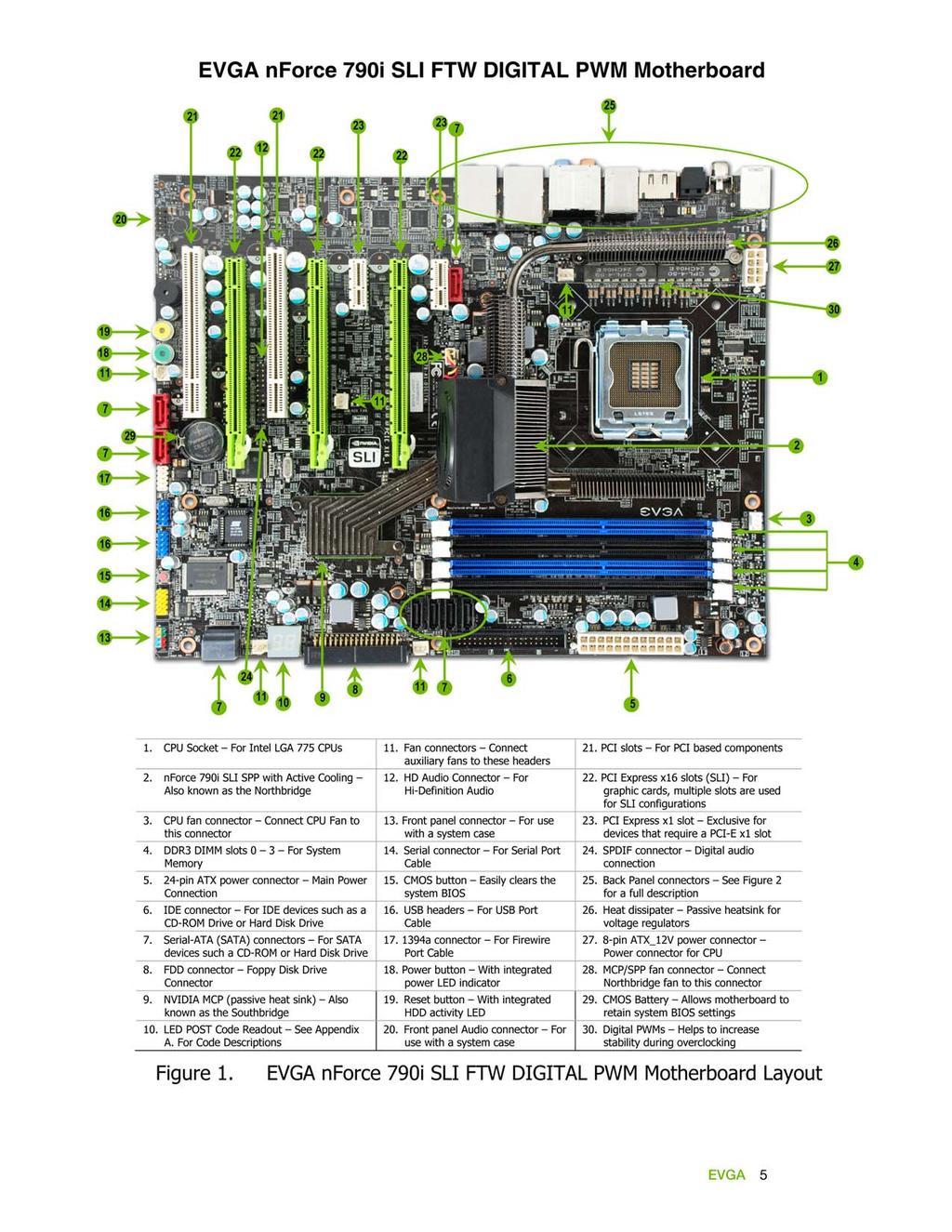
14 PS/2 Mouse Port 2. PS/2 Keyboard Port 3. Coaxial SPDIF output 4. Optical SPDIF output 5. esata port 6. USB 2.0 ports (Six) Audio Port 2-Channel 6-Channel 8-Channel Blue Line-In Line-In Line-In Green Line-Out Front Speaker Out Front Speaker Out Pink Mic In Mic In Mic In Orange Center/Subwoofer Center/Subwoofer Black Rear Speaker Out Rear Speaker Out Grey Side Speaker Out 9. LAN Port with LEDs to indicate status. Activity LED Status Off Blinking (Green) Description No data transmission Data transmission Speed/Link LED Status Yellow Green Off Description 1000 Mbps data rate 100 Mbps data rate 10 Mbps data rate Figure 2. Chassis Backpanel Connectors
15 This section will guide you through the installation of the motherboard. The topics covered in this section are: Preparing the motherboard Installing the CPU Installing the CPU fan Installing the memory Installing the motherboard Connecting cables and setting switches To reduce the risk of fire, electric shock, and injury always follow basic safety precautions. Remember to remove power from your computer by disconnecting the AC main source before removing or installing any equipment from/to the computer chassis.


16 Be very careful when handling the CPU. Make sure not to bend or break any pins in the CPU socket. Hold the processor only by the edges and do not touch the bottom of the processor. Use the following procedure to install the CPU onto the motherboard. Unhook the socket lever by pushing down and away from the socket. Lift the load plate. There is a protective socket cover on the load plate to protect the socket when there is no CPU installed. Remove the protective socket cover from the load plate. Remove the processor from its protective cover, making sure you hold it only by the edges. It is a good idea to save the cover so that whenever you remove the CPU, you have a safe place to store it. Align the notches in the processor with the notches on the socket. Lower the processor straight down into the socket with out tilting or sliding it into the socket Align notches with notches on the CPU Make sure the CPU is fully seated and level in the socket. Close the load plate over the CPU and press down while you close and engage the socket lever.


17 There are many different fan types that can be used with this motherboard. Follow the instruction that came with you fan assembly. Be sure that the fan orientation is correct for your chassis type and your fan assembly. Your new motherboard has four 240-pin slots for DDR3 memory. These slots support 256 MB, 512 MB, 1 GB, and 2 GB DDR3. There must be at least one memory bank populated to ensure normal operation. Use the following the recommendations for installing memory. (See Figure 1 on page 5 for the location of the memory slots.) For memory over 1600MHz(PC ) use slots 2 and 3 (black). One DIMM: Install into slot 3. You can install the DIMM into any slot; however, slot 3 is preferred. Two DIMMS: Install into either slots: 0 and 1 or 2 and 3. The idea is to not have the DIMMS in adjacent slots. Four DIMMS: Install into slots 0, 1, 2, and 3. CPU side DIMM Slot 0 DIMM Slot 2 DIMM Slot 1 DIMM Slot 3 Board edge
18 Use the following procedure to install memory DIMMS. Note that there is only one gap near the center of the DIMM slot. This slot matches the slot on the memory DIMM to ensure the component is installed properly. Unlock a DIMM slot by pressing the module clips outward. Align the memory module to the DIMM slot and insert the module vertically while applying light downward pressure to properly seat the DIMM. The plastic clips at both sides of the DIMM slot automatically lock the DIMM into the connector. The sequence of installing the motherboard into the chassis depends on the chassis you are using and if you are replacing an existing motherboard or working with an empty chassis. Determine if it would be easier to make all the connections prior to this step or to secure the motherboard and then make all the connections. It is normally easier to secure the motherboard first. Use the following procedure to install the I/O shield and secure the motherboard into the chassis. Be sure that the CPU fan assembly has enough clearance for the chassis covers to lock into place and for the expansion cards. Also make sure the CPU Fan assembly is aligned with the vents on the covers. The motherboard kit comes with an I/O shield that is used to block radio frequency transmissions, protects internal components from dust and foreign objects, and promotes correct airflow within the chassis. Before installing the motherboard, install the I/O shield from the inside of the chassis. Press the I/O shield into place and make sure it fits securely. If the I/O shield does not fit into the chassis, you would need to obtain the proper size from the chassis supplier.
19 Most computer chassis have a base with mounting studs or spacers to allow the mother board to be secured to the chassis and help to prevent short circuits. If there are stud(s) that do not align with a mounting hole on the motherboard, it is recommended that you remove that stud(s) to prevent the possibility of a short circuit. In most cases, it is recommended to secure the motherboard using a minimum of eight (8) to ten (10) studs. Carefully place the motherboard onto the studs/spacers located inside the chassis. Align the mounting holes with the studs/spacers. Align the connectors to the I/O shield. Ensure that the fan assembly is aligned with the chassis vents according to the fan assembly instruction. Secure the motherboard with a minimum of eight-to-ten screws. This section takes you through all the connections necessary on the motherboard. This will include: Power Connections 24-pin ATX power (PWR1) 8-pin ATX 12V power (PWR2) Internal Headers Front panel IEEE 1394a USB Headers Audio COM FDD IDE

20 Serial ATA II Chassis Fans Rear panel USB 2.0 Adapter Expansion slots CMOS Clear Button See Figure 1 on page 5 to locate the connectors and button referenced in the following procedure. To support 3-way SLI, this motherboard has the following specific power supply requirements: Minimum 1000 W peak power Six PCI-E power connectors configured in either of the following configurations (see Figure 3): Three 6-pin (3x2) and three 8-pin (4x2) PCI-E power connectors or Six 6-pin (3x2) PCI-E power connectors 8-pin (4x2) PCI-E Connector 6-pin (3x2) PCI-E connector Figure 3. Power Supply Connectors


21 Make sure you have enough power to cover all the expansion cards you will be installing. To determine what you power requirements are for your specific configuration or a certified power supply vendor, refer to. PWR1 is the main power supply connector located along the edge of the board next to the DIMM slots. Make sure that the power supply cable and pins are properly aligned with the connector on the motherboard. Firmly plug the power supply cable into the connector and make sure it is secure. PWR1 connector Plug power cable from power supply to PWR1 Figure 4. Board edge PWR1 Motherboard Connector Table 1. PWR1 Pin Assignments Connector Pin Signal Pin Signal V V V 14-12V 3 GND 15 GND 4 +5V 16 PS_ON 5 GND 17 GND 6 +5V 18 GND 7 GND 19 GND 8 PWROK 20 RSVD 9 +5V_AUX 21 +5V V 22 +5V V 23 +5V V 24 GND


")


22 PWR2, the 8-pin ATX 12V power connection, is used to provide power to the CPU. Align the pins to the connector and press firmly until seated. Backpanel connector edge The IDE connector supports Ultra ATA 133/100/66 IDE hard disk drives. Connect the blue connector (the cable end with a single connector) to the motherboard. Connect the black connector (the cable with two closely spaced black and grey connectors) to the Ultra ATA master device. Connect the gray connector to a slave device. If you install two hard disk drives, you must configure the second drive as a slave device by setting its jumper accordingly. Refer to the hard disk documentation for the jumper settings. If an ATA-66/100 disk drive and a disk drive using any other IDE transfer protocol are attached to the same cable, the maximum transfer rate between the drives may be reduced to that of the slowest drive. IDE Connector

 from")
 from JMicron s JMB362.")
23 The Serial ATA connector is used to connect a Serial ATA I or Serial ATA II device to the motherboard. These connectors support the thin Serial ATA cables for primary storage devices. The current Serial ATA II interface allows up to 300MB/s data transfer rate. There are ten Serial ATA connectors on the motherboard, The six black connectors (SATA1~SATA6) from south bridge chipset that support RAID 0, RAID 1, RAID 5, RAID 0+1 and JBOD configurations and four connectors (SATA7~SATA10) from JMicron s JMB362. SATA3 SATA4 SATA5 SATA6 SATA 1 (bottom) SATA 2 (top) SATA 8 SATA 9 SATA 10 SATA 7 Connector with esata support.
: PWRLED Attach the front panel power LED cable to these two pins of the header. The Power LED indicates the system s status.")
24 The front panel header on this motherboard is used to connect the following four cables. (see Table 2 for pin definitions): PWRLED Attach the front panel power LED cable to these two pins of the header. The Power LED indicates the system s status. When the system is turned on, the LED is on. When the system is turned off, the LED is off. When the system is in S1, S1, S3, S4 standby, the LED will blink. Some chassis do not have all four cables. Be sure to match the name on the connectors to the corresponding pins. PWRSW Attach the power button cable from the case to these two pins. Pressing the power button on the front panel turns the system on and off rather than using the onboard power button. HD_LED Attach the hard disk drive indicator LED cable to these two pins. The HDD indicator LED indicates the activity status of the hard disks. RESET Attach the reset button cable from the front panel of the case to the these two pins. The system restarts when the reset button is pressed. Table 2.Front Panel Header Pins Pin Signal 1 HD_PWR HD_LED 3 HD Active 2 PWR LED PWRLED 4 STBY LED 5 Ground RESET 7 RST BTN 6 PWR BTN PWRSW 8 Ground No Connect 9 +5V Empty 10 Empty


25 The IEEE 1394a (Firewire) expansion cable bracket is provided in the box but if you do not require the additional external connections, you do not need to install it. Secure the bracket to the rear panel of your chassis. Connect the end of the cable to the IEEE 1394a connector on the motherboard. Table 3. IEEE 1394a Connector Pins Connector Pin Signal 1 TPA+ IEEE 1394a Connector 2 TPA- 3 GND GND TPB TPB V V 9 Empty 10 GND


26 This motherboard contains six (6) USB 2.0 ports that are exposed on the rear panel of the chassis (Figure 2). The motherboard also contains two 10- pin internal header connectors onboard that can be used to connect an optional external bracket containing four (4) USB 2.0 ports. Secure the bracket to the rear panel of your chassis. Connect the two ends of the cables to the USB 2.0 headers on the motherboard. Table 4. USB 2.0 Header Pins Connector Pin Signal 1 5V_DUAL USB 2.0 Header Connector 3 Data- 5 Data+ 7 GND 9 Empty Pin Signal 2 5V_DUAL 4 Data- 6 Data+ 8 GND 10 No Connect


27 The audio connector uses the AC97 standard and provides two kinds of audio output choices: Front Audio and Rear Audio. The front Audio supports retasking function. Table 5. Front Audio Connector Connector Pin Signal Front Audio Connector 1 PORT1_L AUD_GND 3 PORT1_R 4 PRECENCE_J 5 PORT2_R 6 SENSE1_RETURN 7 SENSE_SEND 8 Empty 9 PORT2_L 10 SENSE2_RETURN


28 The HD Audio connection supports HD audio standard. Use this if the case does not use the AC97 connectors. Table 6. HD Audio Connector Connector Pin Signal 1 BCLK HD audio Connector 2 GND 3 RESET# V 5 SYNC 6 GND 7 SDATA_OUT V 9 SDATA_IN V 11 SDATA_IN1 12 KEY 13 NC V_DUAL 15 SDATA_IN2 16 GND

29 The SPDIF header is used to connect to an NVIDIA graphics card for HDMI audio. Connector Pin Signal SPDIF Audio Connector 1 Power 2 No Pin 3 SPDIF 4 SPDIFI 5 GROUND 6 GROUND
30


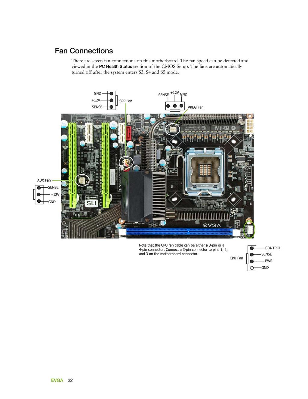
31 System fan connector Fan Connector 3 2 GND +12V SENSE Chassis fan connector Chassis fan connector The motherboard kit provides a serial COM port bracket for your system. Connect one side of the cable to the header and then attach the serial COM device to the other side of the cable.
.")


32 The motherboard supports a standard 360K, 720K, 1.2M, 1.44m, and a 2.88M floppy disk drive (FDD). The EVGA nforce 790i SLI FTW motherboard contains seven expansion slots, five PCI Express slots and two PCI slots PCI slot 1 PCIe x16 slot 2 PCI slot 2 PCIe x16 slot 3 PCIe x1 slots PCIe x16 slot 1 (Primary)
33 The two PCI slots support many expansion cards such as a LAN card, USB card, SCSI card and other cards that comply with PCI specifications. When installing a card into the PCI slot, be sure that it is fully seated. Secure the card s metal bracket to the chassis back panel with the screw used to hold the blank cover. There are two PCI Express x1 slots that are designed to accommodate less bandwidth-intensive cards, such as a modem or LAN card. The x1 slots provide 250 MB/sec bandwidth. These three PCI Express x16 slots are reserved for graphic or video cards. The bandwidth of the x16 slot is up to 4GB/sec (8GB/sec concurrent). The motherboard supports three PCI-Express graphics cards using NVIDIA s SLI technology. When installing a PCI Express x16 card, be sure the retention clip snaps and locks the card into place. If the card is not seated properly, it could cause a short across the pins. Secure the card s metal bracket to the chassis back panel with the screw used to hold the blank cover.
34 These onboard buttons include RESET, POWER and Clear CMOS. Easily turn on/off the system, and conveniently clear the CMOS. The motherboard uses the CMOS ROM to store all the set parameters in the bios. The CMOS can be cleared by using the following procedure: Turn off the AC power supply. Press and hold the clear CMOS button for 10 seconds. Turn the AC power supply back on. These onboard buttons turn the system on/off easily and is especially handy for debugging or testing the system. The POWER button with LED indicates the system s status. When the system is powered on status, the LED is green. When the system is in Standby mode, the LED is yellow. The RESET button with LED indicates the activity status of the hard disks. The LED is orange. RESET Button POWER Button Clear CMOS Button


35 Provides a two-digit POST code to allow for quick and easy debugging. Debug LED Theses LEDs indicate the system status. POWER LED (Green): When the system is powered on, the LED is on. DIMM LED (Yellow): When the memory slot has power, the LED is on. STANDBY LED (Blue): When the system is in standby mode, the LED is on. CPU HOT LED (Red): When the CPU is overheating, the LED is on. POWER LED DIMM LED STANDBY LED CPU HOT LED
36 This section discusses how to change the system settings through the BIOS Setup menus. Detailed descriptions of the BIOS parameters are also provided. This section includes the following information: Enter BIOS Setup Main Menu Standard CMOS Features Advanced BIOS Features Advanced Chipset Features Integrated Peripherals Power Management Setup PnP/PCI Configurations PC Health Status Frequency/Voltage Control
37 The BIOS is the communication bridge between hardware and software. Correctly setting the BIOS parameters is critical to maintain optimal system performance. Use the following procedure to verify/change BIOS settings. Power on the computer. Press the Del key when the following message briefly displays at the bottom of the screen during the Power On Self Test (POST). Press F1 to continue, DEL to enter Setup. Pressing Del takes you to the Phoenix-Award BIOS CMOS Setup Utility. It is strongly recommended that you do not change the default BIOS settings. Changing some settings could damage your computer. The main menu allows you to select from the list of setup functions and two exit choices. Use the Page Up and Page Down keys to scroll through the options or press Enter to display the associated submenu. Use the arrow keys to position the selector in the option you choose. To go back to the previous menu, press Esc. Note that on the BIOS screens all data in white is for information only, data in yellow is changeable, data in blue is non-changeable, and data in a red box is highlighted for selection.
38 - Phoenix AwardBIOS CMOS Setup Utility Standard CMOS Features Advanced BIOS Features Advanced Chipset Features Integrated Peripherals Power Management Setup PnP/PCI Configurations PC Health Status Esc : Quit F10 : Save & Exit Setup Frequency/Voltage Control Load Fail-Safe Defaults Load Optimized Defaults Set Supervisor Password Set User Password Save & Exit Setup Exit Without Saving : Select Item Time, Date, Hard Disk Type.., Figure 5. BIOS CMOS Setup Utility Main Menu Standard CMOS Features Use this menu to set up the basic system configuration. Advanced BIOS Features Use this menu to set up the advanced system features and boot sequence. Advanced Chipset Features Use this menu to optimize system performance and configure clocks, voltages, memory timings, and more. Integrated Peripherals Use this menu to set up onboard peripherals such as IDE, RAID, USB, LAN, and MAC control. Power Management Setup Use this menu to configure power management, power on, and sleep features. PnP/PCI Configurations Use this menu to modify the system s Plug-and-Play and PCI configurations. PC Health Status Use this menu to monitor the real-time system status of your PC, including temperature, voltages, and fan speed.
39 The following items on the CMOS Setup Utility main menu are commands rather than submenus: Load Fail-Safe Defaults Load Fail-Safe defaults system settings. Load Optimized Defaults Load Optimized defaults system settings. Set Supervisor Password/Set User Password Use this command to set, change, and disable the password used to access the BIOS menu. Save & Exit Setup Use this command to save settings to CMOS and exit setup. Exit Without Saving Use this command to abandon all setting changes and exit setup.
40 The Standard CMOS Features menu is used to configure the standard CMOS information, such as the date, time, HDD model, and so on. Use the Page Up and Page Down keys to scroll through the options or press Enter to display the submenu. Use the arrow keys to position the selector in the option you choose. To go back to the previous menu, press Esc. The information shown in Item Help corresponds to the option highlighted. Phoenix AwardBIOS CMOS Setup Utility Standard CMOS Features Date (mm:dd:yy) Sat, Jul Time (hh:mm:ss) 12 : 48: 23 Item Help IDE Channel 0 Master IDE Channel 0 Slave SATA 1 (A0) SATA 2 (A1) SATA 3 (B0) SATA 4 (B1) SATA 5 (C0) SATA 6 (C1) Drive A Halt On Base Memory Extended Memory Total Memory [None] [None] [None] [None] [None] [None] [None] [None] [1.44, 3.5 in.] [All, But Keyboard] 640K K K Main Level Change the day, month, year and century :Move Enter:Select +/-/PU/PD:Value F10:Save ESC:Exit F1:General Help F5:Previous Values F6:Fail-Safe Defaults F7:Optimized Defaults Figure 6. Standard CMOS Features Menu Note that all data in white is for information only, data in yellow is changeable, data in blue is non-changeable, and data in a red box is highlighted for selection.
41 Using the arrow keys, position the cursor over the month, day, and year. Use the Page Up and Page Down keys to scroll through dates and times. Note that the weekday (Sun through Sat) cannot be changed. This field changes to correspond to the date you enter. Note that the hour value is shown in a 24-hour clock format. Time is represented as hour : minute : second. Date (mm:dd:yy) Sat, Jul Time (hh:mm:ss) 14 : 48: 43 Use these functions to detect and configure the individual IDE and SATA channels. Select a channel and press Enter to display the IDE/SATA sub-menu. IDE Channel 0 Master IDE Channel 0 Slave SATA 1 (A0) SATA 2 (A1) SATA 3 (B0) SATA 4 (B1) SATA 5 (C0) SATA 6 (C1) Press ENTER to display SATA Channel sub-menu IDE Auto-Detect Extended IDE Drive Access Mode [Press Enter] [None} Auto [None] [None] [None] [None] [None] [None] [None] [None] Press ENTER to display IDE Channel sub-menu IDE HDD Auto-Detect IDE Channel 0 Slave Access Mode Capacity [Press Enter] [Manual} [CHS] 0 MB Cylinder [ 0] Head [ 0] Precomp [ 0] Landing Zone [ 0] Sector [ 0] Capacity 0 MB Cylinder 0 Head 0 Precomp 0 Landing Zone 0 Sector 0
42 Press Enter to auto-detect IDE and SATA channels in the system. Once the channel is detected, the values for Capacity, Cylinder, Heads, Precomp, Landing Zone, and Sector are automatically filled in. None There is no HDD installed or set. Auto The system can auto-detect the hard disk when booting up. Manual When you set the channel to [Manual] and change Access Mode to [CHS], you can then enter the number of cylinders, heads, Precomp, landing zone, and sector. You can manually enter the values or you can press Enter to display a window that tells you the min and max values. IDE HDD Auto-Detect [Press Enter] IDE Channel 0 Slave Access Mode Capacity [Manual} [CHS] 0 MB Cylinder...0 Head [ 0] Precomp [ 0] Landing Zone [ 0] Sector [ 0] Press ENTER to display sub-menu or enter number manually Cylinder The BIOS supports the following HDD Access Modes: Min= 0 Max=65535 Key in a DEC number : CHS For HDD less than 528 MB. LBA For HDD greater than 528 MB and supporting LBA (Logical Block Addressing). Large For HDD greater than 528 MB but not supporting LBA. Auto Recommended mode. :Move ENTER:Accept ESC:Abort The Drive A option allows you to select the kind of FDD to install. Options are:
43 Drive A Halt On None 360K, 5.25 in. 1.2M, 5.25 in. 720K, 3.5 in. 1.44M, 3.5 in. 2.88M, 3.5 in. [1.44, 3.5 in.] [All, But Keyboard] Press ENTER to display sub-menu Drive A None... [ ] 360K, 5.25 in.... [ ] 1.2M, 5.25 in.... [ ] 720K, 3.5 in.... [ ] 1.44M, 3.5 in.... [ ] 2.88M, 3.5 in.... [ ] :Move ENTER:Accept ESC:Abort Use the Page Up and Page Down keys to scroll through the options or press Enter to display the sub-menu. Use the arrow keys to position the selector in the option you choose. Press Enter to accept the changes and return to the Standard CMOS Features menu. Halt On determines whether or not the computer stops if an error is detected during power on. Use the Page Up and Page Down keys to scroll through the options or press Enter to display the Halt On sub-menu. Use the arrow keys to position the selector in the option you choose. Press Enter to accept the changes and return to the Standard CMOS Features menu. Drive A Halt On [1.44, 3.5 in.] [All, But Keyboard] All Errors Whenever the BIOS detects a nonfatal error, the system stops and prompts you. No Errors System boot does not stop for any detected errors. All, But Keyboard System boot does not stop for keyboard errors, but does stop for all other errors. All, But Diskette Press ENTER to display sub-menu Halt On All Errors... [ ] No Errors... [ ] All, But Keyboard... [ ] All, But Diskette... [ ] All, But Disk/Key... [ ] :Move ENTER:Accept ESC:Abort The system boot does not stop for a diskette error but will stop for all other errors. All, But Disk/Key The system boot does not stop for a keyboard or disk error, but will stop for all other errors.
44 These settings are display-only values that are determined by the BIOS POST (Power-On Self Test). Base Memory Extended Memory Total Memory Base Memory BIOS POST determines the amount of base (or conventional) memory installed in the system. 640K K K Extended Memory BIOS determines how much extended memory is present during the POST. Total Memory This value represents the total memory of the system.
45 Access the Advanced BIOS Features menu from the CMOS Utility Setup screen. Use the Page Up and Page Down keys to scroll through the options or press Enter to display the sub-menu. Use the arrow keys to position the selector in the option you choose. To go back to the previous menu, press Esc. The options that have associated sub-menus are designated by a, which precedes the option. Press Enter to display the sub-menus. Phoenix AwardBIOS CMOS Setup Utility Advanced BIOS Features Hard Disk Boot Priority [Press Enter] CD-ROM Boot Priority [Press Enter] Network Boot Priority [Press Enter] CPU Internal Cache [Enabled] Quick Power On Self Test [Enabled] First Boot Device [Removable] Second Boot Device [CDROM] Third Boot Device [Hard Disk] Boot Other Device [Enabled] Boot Up NumLock Status [On] Security Option [Setup] APIC Mode [Enabled] MPS Version Control For OS [1.4] Full Screen LOGO Show [Disabled] Main Level Item Help Select Removable Boot Device Priority :Move Enter:Select +/-/PU/PD:Value F10:Save ESC:Exit F1:General Help F5:Previous Values F6:Fail-Safe Defaults F7:Optimized Defaults Figure 7. Advanced BIOS Features Menu Note that all data in white is for information only, data in yellow is changeable, data in blue is non-changeable, and data in a red box is highlighted for selection.
46 Use this option to select the priority for HDD startup. Press Enter to see the list of bootable devices in your system. Use the arrow keys to go to the various devices. Then use the + or keys to move the device priority up or down in the list. To go back to the previous menu, press Esc. 1. Ch0. : ST A 2. Bootable Add-in Cards Use the + and keys to move the priority of the device within the list Use this option to select the priority for CD-ROM startup. Press Enter to see the list of removable devices in your system. Use the arrow keys to go to the various devices. Then use the + or keys to move the device priority up or down in the list. To go back to the previous menu, press Esc. 1. Ch0 M. : BENQ DVD DC DW1810 Use this option to select the priority for network startup. Select Network Boot Priority and press Enter to view available networks. Use the arrow keys to go to the various devices. Then use the + or keys to move the device priority up or down in the list. To go back to the previous menu, press Esc. 1. Network 0 : <description of network> 2. Network 1 : <description of network> Use this option to enable or disable the CPU internal cache. Use the Page Up and Page Down keys to scroll through the options or press Enter to display the options in a sub-menu. Use the arrow keys to position the selector in the option you choose.
47 Enabling this option allows the system to skip certain test while booting, which reduces the time needed to boot the system. Use the Page Up and Page Down keys to toggle between Enable and Disable. Use this option to set the priority sequence of the devices booted at power on. Use the Page Up and Page Down keys to scroll through the options or press Enter to display the sub-menu. Use the arrow keys to position the selector in the option you choose. First Boot Device Removable... [ ] Hard Disk... [ ] CDROM... [ ] Network... [ ] Disabled... [ ] :Move ENTER:Accept ESC:Abort With the option set to Enable, the system boots from some other device if the first/second/third boot devices fail. This option allows you to select the power-on state of NumLock. Select On to activate the keyboard NumLock when the system is started. Select Off to disable the NumLock key.
48 The Security Options allows you to require a password every time the system boots or only when you enter setup. Select Setup to require a password to gain access to the CMOS Setup screen. Select System to require a password to access the CMOS Setup screen and when the system boots. Use this function to enable or disable the Advanced Programmable Interrupt Controller (APIC). If you disable this option, you also disable the MPS Version Control for OS option. Use this function to select the Multi-Processor Specification (MPS) version that BIOS passes to the operating system. Use the Page Up and Page Down keys to scroll through the options. This option allows you to enable or disable the display of the full-screen logo when the system boots. Use the Page Up and Page Down keys to toggle between Enable and Disable
49 Select Advanced Chipset Features from the CMOS Setup Utility menu and press Enter to display the functions of the Advanced Chipset Functions menu. Phoenix AwardBIOS CMOS Setup Utility Advanced Chipset Features System BIOS Cacheable HPET Function [Disabled] [Enable] Item Help Main Level :Move Enter:Select +/-/PU/PD:Value F10:Save ESC:Exit F1:General Help F5:Previous Values F6:Fail-Safe Defaults F7:Optimized Defaults Figure 8. Advanced Chipset Features This function allows you to enable or disable caching the system BIOS. This function allows you to enable or disable the High Precision Even Timer (HPET). When Enabled, HPET is used as the timing hardware for multimedia and other time-sensitive application. When HPET is Disabled, the APIC timer is used.
50 Select Integrated Peripherals from the CMOS Setup Utility menu and press Enter to display the Integrated Peripherals menu. Phoenix AwardBIOS CMOS Setup Utility Integrated Peripherals IDE Function Setup RAID Config USB Config MAC Config IEEE 1394 Controller JMicron AHCI (SATA 7/8) JMicron AHCI (SATA 9/10) HD Audio Onboard FDC controller Onboard Serial Port 1 [Press Enter] [Press Enter] [Press Enter] [Press Enter] [Enabled] [Enabled] [Enabled] [Auto] [Enabled] [3F8/IRQ4] Main Level Item Help :Move Enter:Select +/-/PU/PD:Value F10:Save ESC:Exit F1:General Help F5:Previous Values F6:Fail-Safe Defaults F7:Optimized Defaults Figure 9. Integrated Peripherals Menu
51 Press Enter to display the IDE Function Setup menu. OnChip IDE Channel0 [Enabled] Primary Master PIO [Auto] Primary Slave PIO [Auto] Primary Master UDMA [Auto] Primary Slave UDMA [Auto] IDE DMA transfer access [Enabled] Serial-ATA Controller [All Enabled] IDE Prefetch Mode [Enabled] IDE HDD Block Mode [Enabled] OnChip IDE Channel0 Use this function to enable or disable the onchip IDE Channel0. When disabled, the Primary Master/Slave functions are changed to Auto and cannot be changed. OnChip IDE Channel0 [Disabled] x Primary Master PIO Auto x Primary Slave PIO Auto x Primary Master UDMA Auto x Primary Slave UDMA Auto IDE DMA transfer access [Enabled] Serial-ATA Controller [All Enabled] IDE Prefetch Mode [Enabled] IDE HDD Block Mode [Enabled] Primary Master/Slave PIO When OnChip IDE Channel0 is set to [Enabled], you can select a mode for the primary Master and Slave PIO. Select from Auto, or Mode 1 through Mode 4. Primary Master/Slave UDMA When OnChip IDE Channel0 is set to [Enabled], you can disable the primary Master and Slave UDMA or set it to [Auto]. IDE DMA transfer access Use this function to enable or disable IDE DMA transfer access. Serial-ATA Controller This function allows you to enable specific SATA controllers. The options available are [SATA-0], [SATA-0+1], [Enabled], and [Disabled]. IDE Prefetch Mode Use this function to enable or disable the IDE Prefetch mode.
52 IDE HDD Block Mode Using this function on the Integrated Peripherals menu allows your IDE hard drive needs to support block mode. Select [Enabled] to automatically detect the optimal number of block read/writes per sector the drive can support. Select [Disabled] if your drive does not support block mode. Press Enter to display the RAID Config menu. RAID Enable SATA 1 (A0) RAID SATA 2 (A1) RAID SATA 3 (B0) RAID SATA 4 (B1) RAID SATA 5 (C0) RAID SATA 6 (C1) RAID [Enabled] [Disabled] [Disabled] [Disabled] [Disabled] [Disabled] [Disabled] RAID Enable Use this function to enable or disable RAID. When RAID is set to [Disabled], all SATA functions are changed to Disabled and cannot be changed. RAID Enable x SATA 1 (A0) RAID x SATA 2 (A1) RAID x SATA 3 (B0) RAID x SATA 4 (B1) RAID x SATA 5 (C0) RAID x SATA 6 (C1) RAID [Disabled] Disabled Disabled Disabled Disabled Disabled Disabled SATA x Primary/Secondary When RAID Enable is set to [Enabled], you can enable or disable the various SATA functions. Press Enter to display the USB Config menu. OnChip USB USB Keyboard Support USB Mouse Support [V1.1+V2.0] [Enabled] [Enabled] OnChip USB Use this function to enable specific versions of the USB or disable the onchip USB. When the onchip USB is set to [Disabled], the keyboard and mouse support functions are set to V1.1+V2.0 and cannot be changed. Versions that can be selected are [V1.1+V2.0] or [V1.1]. OnChip USB x USB Keyboard Support x USB Mouse Support [Disabled] Enabled Enabled
53 USB Keyboard/Mouse Support Use these function to enable or disable the onchip USB support of the keyboard and/or mouse. Press Enter to display the MAC Config menu. MAC0 LAN MAC1 LAN [Auto] [Auto] MACx LAN Use these functions to set the MAC0 and/or MAC1 LANs to Auto or disable their functions. This function on the Integrated Peripherals menu allows you to enable or disable the IEEE 1394a (Firewire) interface. This function on the Integrated Peripherals menu allows you to enable or disable SATA port 7 and 8(eSATA). This function on the Integrated Peripherals menu allows you to enable or disable SATA port 9 and 10. This function on the Integrated Peripherals menu allows you to enable or disable the high-definition audio function. This function on the Integrated Peripherals menu allows you to enable or disable the onboard FDC controller function. This function on the Integrated Peripherals menu allows you to select the onboard serial port 1 function. Options are [3F8/IRQ4], [2E8/IRQ3], [3E8/IRQ4], [Auto], and [Disabled].
54 Select Power Management Setup from the CMOS Setup Utility menu and press Enter to display the Power Management Setup menu. Phoenix AwardBIOS CMOS Setup Utility Power Management Setup ACPI function APCI Suspend Type Soft-Off by PBTN WOL(PME#) From Soft-Off WOR(RI#) From Soft-Off PWRON After PWR-Fail [Enabled] [S1&S3] [Instant-Off] [Disabled] [Disabled] [Off] Main Level Item Help Power-on by Alarm [Disabled] x Day of Month Alarm 0 x Time (hh:mm:ss) Alarm 0 : 0 : 0 POWER ON Function x KB Power ON Password x Hot Key Power On [BUTTON ONLY] Enter Ctrl-F1 :Move Enter:Select +/-/PU/PD:Value F10:Save ESC:Exit F1:General Help F5:Previous Values F6:Fail-Safe Defaults F7:Optimized Defaults Figure 10. Power Management Setup Menu This function on the Power Management Setup menu allows you to enable or disable the ACPI function. This function on the Power Management Setup menu allows you to select an ACPI Suspend Type. Types to select from are [S1&S3], [S1(POS)], and [S3(STR)].
55 This function on the Power Management Setup menu allows you to set Soft-Off by PBNT to [Instant-Off] or [Delay 4 Sec]. This function on the Power Management Setup menu allows you to enable or disable WOL(PMW#) from soft-off. This function on the Power Management Setup menu allows you to enable or disable WOR(RI#) from soft-off. This function enables your computer to automatically restart or return to its last operating status after power returns from a power failure. Off: The system stays off after a power failure. On: The system stays on after a power failure This function on the Power Management Setup menu allows you to enable or disable the Power-on by alarm function. Set to [Disable] to prevent power-on by alarm. When set to [Enable], you can manually put in the day of the month and the time of the alarm. Power-on by Alarm [Disabled] Day of Month Alarm [ 0] Time (hh:mm:ss) Alarm [0 : 0 : 0] To enter a day or time, use the Page Up and Page Down keys to scroll through numbers or enter the number using the keyboard number or the + and keys.
56 This function on the Power Management Setup menu allows you to define the power-on function. Options for this function are: BUTTON ONLY Keyboard 98 Password When [Password] is selected, the KB Power ON Password function is enabled so that you must enter a password. POWER ON Function KB Power ON Password x Hot Key Power On [Password] [Enter] Ctrl-F1 Hot Key Power On When [Hot Key] is selected, the Hot key Power On function is enabled so that you must select a keyboard key as the hot key. To select a hot key use Ctrl+F1 though Ctrl+F12 Mouse Left POWER ON Function x KB Power ON Password Hot Key Power On Mouse Right Any Key [Hot key] Enter [Ctrl-F1]
57 Select PnP/PCI Configuration from the CMOS Setup Utility menu and press Enter to display the PnP/PCI Configuration menu. Phoenix AwardBIOS CMOS Setup Utility PnP/PCI Configuration Init Display First [PCI Slot] Item Help Resources Controlled By x IRQ Resources [Auto(ESCD)] Press Enter Main Level PCI/VGA Palette [Disabled] PCI Latency Timer(CLK) [32] ** PCI Express relative items ** Maximum Payload Size [4096] :Move Enter:Select +/-/PU/PD:Value F10:Save ESC:Exit F1:General Help F5:Previous Values F6:Fail-Safe Defaults F7:Optimized Defaults Figure 11. PnP/PCI Configuration Menu This function on the PnP/PCI Configuration menu allows you to define if the initial display is in the PCI slot or in the PCI Express slot. Options are [PCI Slot] and [PCIEx].
58 This function on the PnP/PCI Configuration menu allows you to define if the BIOS can automatically configure all the boot and plug-and-play compatible devices or if you can manually select IRQ, DMA, and memory base address fields. Select [Auto(ESCD)] if you want the BIOS to automatically populate these fields. If you select [Manual] so you can assign the resources, IRQ Resources is enabled for input. Resources Controlled By [Auto(ESCD)] x IRQ Resources Press Enter Resources Controlled By [Manual)] IRQ Resources [Press Enter] To enable this field for input, set Resources Controlled By to [Manual]. With this field enabled, press Enter to see options. IRQ-5 assigned to IRQ-9 assigned to IRQ-10 assigned to IRQ-11 assigned to IRQ-14 assigned to IRQ-15 assigned to [PCI Device] [Reserved] [PCI Device] [PCI Device] [PCI Device] [PCI Device] Use Legacy ISA for devices compliant with the original PC AT Bus specification. Use PCI/ISA PnP for devices compliant with the plug-and-play standard, whether designed for PCI or ISA Bus architecture. This item is designed to overcome problems that may be caused by some nonstandard VGA cards..
59 This item controls how long each PCI device can hold the bus before another takes over. When set to higher values, every PCI device can conduct transactions for a longer time and thus improve the effective PCI bandwidth. For better PCI performance, you should set the item to higher values. The options are 0 through 255. This function on the PnP/PCI Configuration menu allows you to set the maximum TLP payload size (in bytes) for the PCI Express devices. Use the Page Up and Page Down keys to scroll through sizes or enter the number using the keyboard numbers or use the + and keys to go up and down the list of sizes.
60 Select PC Health Status from the CMOS Setup Utility menu and press Enter to display the PC Health Status menu. Phoenix AwardBIOS CMOS Setup Utility PC Health Status Dynamic Fan Control [Press Enter] CPU 38ºC/ 100ºF Board 42ºC/ 108ºF MCP55 59ºC/ 138ºF CPU Core 1.27V +5V 4.97V Memory 1.48V nforce SPP 1.31V +3.3V 3.21V +12V 11.91V +Vbat 3.02V CPU Fan Speed Chassis Fan Speed Chassis Fan2 Speed Aux Fan Speed nforce Fan Speed 4272 RPM 0 RPM 0 RPM 4891 RPM 0 RPM Main Level Item Help :Move Enter:Select +/-/PU/PD:Value F10:Save ESC:Exit F1:General Help F5:Previous Values F6:Fail-Safe Defaults F7:Optimized Defaults Figure 12. PC Health Status Menu All of the values shown in Blue are dynamic and change as the speed and voltages of the various components change with system usage.
61 Press Enter to display the Dynamic Fan Control menu. CPU Fan Speed Control [SmartFan] If temp > 70ºC, Set Fan Speed 100% If temp < 30ºC, Set Fan Speed 1% x Manual Fan Speed, % 100 Chassis Fan Speed Control [SmartFan] If temp > 70ºC, Set Fan Speed 100% If temp < 30ºC, Set Fan Speed 1% x Manual Fan Speed, % 100 nforce Fan Speed Control [Auto] x Manual Fan Speed, % 100 AUX Fan Speed Ctrl, % [100] Chassis Fan2 Speed Ctrl, % [100] CPU VREG Fan Control [on] Use this menu to control the speed of the various fans on the motherboard. Set CPU fan speed to [SmartFan] when you want the speed of the fans automatically controlled based on temperature. To set the fan speed to a constant rate, select [Manual] and then enter the speed from 0% to 100%. Set the desired speed for the Aux, nforce, and Chassis fans from 0% to 100%. The system defaults to 100%.
62 Select Frequency/Voltage Control from the CMOS Setup Utility menu and press Enter to display the Frequency/Voltage Control menu. Phoenix AwardBIOS CMOS Setup Utility Frequency/Voltage Control System Clocks FSB & Memory Config CPU Feature System Voltages [Press Enter] [Press Enter] [Press Enter] [Press Enter] Main Level Item Help Load timing/voltage set Save timing/voltage set [Press Enter] [Press Enter] :Move Enter:Select +/-/PU/PD:Value F10:Save ESC:Exit F1:General Help F5:Previous Values F6:Fail-Safe Defaults F7:Optimized Defaults Figure 13. Frequency/Voltage Control Menu
63 Select System Clocks from the Frequency/Voltage Control menu and press Enter to display the System Clocks menu. From this menu, you are able to specify frequency settings, HT multipliers, and Spread Spectrum settings. Note that in Figure 9, all of the options are listed. On the actual BIOS screen, you will need to scroll down to see all the options. Phoenix AwardBIOS CMOS Setup Utility System Clocks Parameters Settings Current Vale **Frequency Settings** CPU Freq, MHz FSB Reference Clock, MHz CPU Multiplier [11 X] 11X PCIe x16_1 & x16_2, MHz [Auto] 100 PCIe x16_3, MHz [Auto] 100 SPP<->MCP Ref Clock, MHz [Auto] 100 **HT Multiplier** nforce SPP --> nforce MCP [5 x] nforce SPP <-- nforce MCP [5 x] Main Level Item Help CPU frequency multiplier. CPU core clock = FSB Ref Clock/4 * CPU Multiplier **Spread Spectrum** CPU Spread Spectrum [Center Spread] HT Spread Spectrum [Auto] PCIe Spread Spectrum(SPP) [Disabled] PCIe Spread Spectrum(MCP) [Auto] SATA Spread Spectrum [Disabled] :Move Enter:Select +/-/PU/PD:Value F10:Save ESC:Exit F1:General Help F5:Previous Values F6:Fail-Safe Defaults F7:Optimized Defaults Figure 14. System Clocks Menu Note that all data in white is for information only, data in yellow is changeable, data in blue is non-changeable, and data in a red box is highlighted for selection.
64 CPU Freq, MHz This value is set by the CPU Multiplier (value cannot be changed by the user). FSB Reference Clock. MHz This value is set by the system (value cannot be changed by the user). To change the SLI-Ready memory, FSB memory, and memory timing, go to the FSB & Memory screen. CPU Multiplier This value changes the CPU Frequency value depending on the value you choose. Use the Page Up and Page Down keys to scroll through the options. The options are from 6 X through 60 X. PCIe x16_1, MHz & PCIe x16_2, MHz Use the Page Up and Page Down keys to scroll through the frequency options for the PCI Express Bus, Slot 1 (the black slot closest to the CPU) and Slot 2 (the black slot farthest from the CPU). Note that as you go higher in value, PCIe Spread Spectrum(SPP) is disabled and cannot be changed from this status. PCIe x16_3, MHz Use the Page Up and Page Down keys to scroll through the frequency options for the PCI Express Bus, Slot 3 (the blue slot in the middle). SPP< >MCP Ref Clock, MHz Use the Page Up and Page Down keys to scroll through the frequency options for the reference clock between the SPP chip and the MCP chip. nforce SPP > nforce MCP Use the Page Up and Page Down keys to scroll through the HT multiplier options and set the link speed from the SPP chip to the MCP chip. Values are [1 x] through [5 x]. nforce MCP < nforce SPP Use the Page Up and Page Down keys to scroll through the HT multiplier options and set the link speed from the MCP chip to the SPP chip. Values are [1 x] through [5 x].
65 CPU Spread Spectrum This option reduces the EMI generated by the CPU. Options are [Disabled] and [Center Spread]. HT Spread Spectrum This option reduces the EMI generated by the HT. Options are [Disabled] and [Auto]. PCIe Spread Spectrum (SPP) This option reduces the EMI generated by the SPP PCI-E. Options are [Disabled] and [Auto]. This option reverts to Disabled and cannot be changed when the value for PCIe x16_1 exceeds 100MHz. PCIe Spread Spectrum(MCP) This option reduces the EMI generated by the PCI-E. Options are [Disabled] and [Auto] SATA Spread Spectrum This option reduces the EMI generated by the S-ATA. Options are [Disabled] and [Down Spread].
66 Select FSB & Memory Config from the Frequency/Voltage Control menu and press Enter to display the FSB & Memory Config menu. This menu provides the means to set SLI-Ready memory, FSB memory, and memory timing. Phoenix AwardBIOS CMOS Setup Utility FSB & Memory Config Parameters EPP 2.0 Memory Settings Current Value [Disabled] Disabled Item Help CPU Freq, MHz CPU Multiplier 11X 11X FSB Memory Clock Mode [Auto] x FSB menory Ratio Auto x FSB (QDR), MHz Auto Actual FSB (QDR), MHz x MEM (DDR), MHz Auto Actual MEM (DDR), MHz Memory Timing Setting [Press Enter] Main Level Auto realizes the complete optimized memory settings when EPP 2.0 memory is installed Optimized memory settings by allowing X% CPU overclocking Figure 15. :Move Enter:Select +/-/PU/PD:Value F10:Save ESC:Exit F1:General Help F5:Previous Values F6:Fail-Safe Defaults F7:Optimized Defaults FSB & Memory Config Menu EPP 2.0 Memory Use the Page Up and Page Down keys to scroll through the EPP 2.0 Memory options. The options are: Disabled CPUOC 0% CPUOC 1% CPUOC 2% CPUOC 3% CPUOC 4% CPUOC 5% Auto Expert CPU overclocking may require manual overvoltaging of the CPU to improve system stability
67 When you select one of the CPUOC x% options, the FSB - Memory Clock Mode is set to Unlinked and cannot be changed until EPP 2.0 Memory is set to Disable. FSB and Memory Clock Mode Use the Page Up and Page Down keys to scroll through the FSB and Memory Clock Mode options. The options are: Auto This is the optimal setting since it sets the FSB and memory speeds automatically. Linked When Link is selected, FSB-Memory Ratio and FSB (QDR), MHz are changed to editable and the FSB speed can be entered manually. As the FSB speed is changed, CPU Freq, MHz changes proportionally. CPU Freq, MHz CPU Multiplier 11X 11X FSB Memory Clock Mode [Linked] FSB Memory Ratio [Auto] FSB (QDR), MHz [1067] Actual FSB (QDR), MHz x MEM (DDR), MHz Auto Unlinked When Unlink is selected, FSB (QDR), MHz and MEM (DDR), MHz are changed to editable and the FSB and memory speeds can be entered manually. As the FSB speed is changed, CPU Freq, MHz changes proportionally. FSB Memory Clock Mode [Unlinked] x FSB Memory Ratio Auto FSB (QDR), MHz [1067] Actual FSB (QDR), MHz MEM (DDR), MHz [1067] Actual MEM (DDR), MHz FSB (QDR), MHz Use the + or keys to scroll through new values for the CPU FSB frequency or type in a new value. Note that the Actual FSB (QDR) reflects the actual frequency that takes effect on a reboot.
68 MEM (DDR), MHz Use the + or keys to scroll through new values for the memory frequency or type in a new value. Note that the Actual MEM (DDR) reflects the actual frequency that takes effect when the system reboots. Memory Timing Setting Press Enter to display the Memory Timing Setting menu. Use this menu to set optimal timings or to manually enter timings. Phoenix AwardBIOS CMOS Setup Utility Memory Timing Setting Parameters Settings Current Value Item Help Memory Timing Setting [Optimal] x tcl (CAS Latency) Auto(7) 7 x trcd Auto(7) 7 x trp Auto(7) 7 x tras Auto(20) 20 x Command Per Clock (CMD) Auto(1T) 1T Main Level Select [Expert] to enter timings manually ** Advanced Memory Settings ** x trrd Auto(4) 4 x trc Auto(27) 27 x twr Auto(10) 10 x twtr Auto(14) 14 x tfaw Auto(21) 21 x tref Auto 7.8uS x trfc Auto 110ns :Move Enter:Select +/-/PU/PD:Value F10:Save ESC:Exit F1:General Help F5:Previous Values F6:Fail-Safe Defaults F7:Optimized Defaults Optimal Use the Page Up and Page Down keys to select Optimal. Optimal prohibits you from manually setting any timing. All timing is set for optimal performance.
69 Expert Use the Page Up and Page Down keys to select Expert. When Expert is selected, all timing categories are enabled for manual input. Note that you should set the value to Optimal to use the manufacturers recommended values. Parameters Settings Current Value Memory Timing Setting [Expert] tcl (CAS Latency) [Auto(7)] 7 trcd [Auto(7)] 7 trp [Auto(7)] 7 tras [Auto(20)] 20 Command Per Clock (CMD) [Auto(1T)] 1T ** Advanced Memory Settings ** trrd [Auto(4)] 4 trc [Auto(27)] 27 twr [Auto(10)] 10 twtr [Auto(14)] 14 tfaw [Auto(21)] 21 tref [Auto] 7.8uS trfc [Auto] 110ns tcl: CAS# latency (options are Auto and 5 through 18). trcd: RAS#-to-CAS# Delay for Read/Write commands to the same bank (options are Auto and 1 through 15). trp: Row Precharge time. This is the Precharge-to-Active or Auto-to- Refresh of the same bank (options are Auto and 1 through 15). tras: This is the minimum RAS# active time (options are Auto and 1 through 63). Command Per Clock: This is the command timing setting on a per clock unit basis (options are Auto, 1 clock and 2 clock). trrd: RAS#-to-RAS# delay of different banks (options are Auto and 1 through 15). trc: RAS#-to-RAS# or auto refresh time of the same bank (options are Auto and 1 through 63). twr: The Write recovery time (options are Auto and 5 through 12). twtr: This is the minimum write-to-read delay with the same chip selected (options are Auto and 1 through 31). tfaw: Minimum four Activate Windows delay time (options are Auto and 1 through 63). tref: This is the DRAM refresh rate (options are Auto, 7.8uS, and 3.9uS).
EVGA assumes you have purchased all necessary parts needed to allow for proper system functionality.
 Before You Begin Parts NOT in the Kit This kit contains all the hardware necessary to install and connect your new EVGA e-7050/610i GPU motherboard with integrated GeForce graphics processing. However,
User Guide. NVIDIA nforce 780i SLI Motherboard. NVIDIA Corporation October, 2007 DU _v01
 User Guide NVIDIA nforce 780i SLI Motherboard October, 2007 DU-03597-001_v01 780i 3-Way SLI Motherboard ii October 17, 2007 DU-03597-001_v01 nforce 780i SLI Motherboard Table of Contents Before You Begin...ix
User Guide. EVGA nforce 650i Ultra Motherboard for Intel Processor. Installation and Configuration. March 2007 EVGA V1.0
 User Guide EVGA nforce 650i Ultra Motherboard for Intel Processor Installation and Configuration March 2007 EVGA V1.0 Installing and Configuring the NVIDIA nforce 650i Ultra Motherboard Table of Contents
User Guide. TF650i Ultra-A7 Motherboard for Intel Processor. Installation and Configuration
 User Guide TF650i Ultra-A7 Motherboard for Intel Processor Installation and Configuration Installing and Configuring the TF650i Ultra-A7 Motherboard Table of Contents Before You Begin...viii Parts NOT
EVGA X58 SLI Micro Motherboard. Table of Contents
 EVGA X58 SLI Micro Motherboard Table of Contents... 1 EVGA X58 SLI Micro Motherboard... 1... 8 Parts NOT in the Kit... 8 Intentions of the Kit... 8 EVGA X58 SLI Micro Motherboard...10 Motherboard Specifications...
User Guide. EVGA X58 Classified3 Motherboard
 User Guide EVGA X58 Classified3 Motherboard Table of Contents Before You Begin... 8 Parts NOT in the Kit... 8 Intentions of the Kit... 9 EVGA X58 CLASSIFIED3 Motherboard... 11 Motherboard Specifications...
Colorful Technology Website:
 Colorful Technology Website: http://www.colorful.cn Thanks for purchasing our based on Intel B250 Chipset motherboard. The motherboard C.B250A-BTC PLUS V20 based on Intel B250 Express Chipset, support
1.1.Packing Contents 1*Colorful C.B250A-BTC V20 motherboard 2*SATA cables 1*Driver/Utility CD 1*User's Guide 1*I/O shield 1.2.MOTHERBOARD SPEC CPU
 Colorful Technology Website: http://www.colorful.cn Thanks for purchasing our based on Intel B250 Chipset motherboard. The motherboard C.B250A-BTC V20 based on Intel B250 Express Chipset, support Intel
C.B250A-BTC V20. User s Manual Motherboard. Colorful Technology Website:
 C.B250A-BTC V20 User s Manual Motherboard Colorful Technology Website: http://www.colorful.cn Copyright This motherboard manual belongs to Colorful Technology and Development CO, LTD. No one is permitted
BIOS SETUP UTILITY. v02.54 (C) Copyright , American Megatrends, Inc. BIOS SETUP UTILITY
 Copyright , American Megatrends, Inc. BIOS SETUP UTILITY") 1 Main OC Tweaker Advanced H/W Monitor Boot Security Exit System Overview System Time System Date BIOS Version Processor Type Processor Speed Microcode Update L1 Cache Size : 384KB L2 Cache Size : 1536KB
1 Main OC Tweaker Advanced H/W Monitor Boot Security Exit System Overview System Time System Date BIOS Version Processor Type Processor Speed Microcode Update L1 Cache Size : 384KB L2 Cache Size : 1536KB
BIOS SETUP UTILITY. v02.54 (C) Copyright , American Megatrends, Inc. BIOS SETUP UTILITY
 Copyright , American Megatrends, Inc. BIOS SETUP UTILITY") 1 Main Smart Advanced H/W Monitor Boot Security Exit System Overview System Time System Date BIOS Version Processor Type Processor Speed Microcode Update L1 Cache Size L2 Cache Size Total Memory DDRII_1
1 Main Smart Advanced H/W Monitor Boot Security Exit System Overview System Time System Date BIOS Version Processor Type Processor Speed Microcode Update L1 Cache Size L2 Cache Size Total Memory DDRII_1
BIOS SETUP UTILITY. v02.54 (C) Copyright , American Megatrends, Inc. BIOS SETUP UTILITY
 Copyright , American Megatrends, Inc. BIOS SETUP UTILITY") 1 Main OC Tweaker Advanced H/W Monitor Boot Security Exit System Overview System Time System Date BIOS Version Processor Type Processor Speed Microcode Update L1 Cache Size : 384KB L2 Cache Size : 1536KB
1 Main OC Tweaker Advanced H/W Monitor Boot Security Exit System Overview System Time System Date BIOS Version Processor Type Processor Speed Microcode Update L1 Cache Size : 384KB L2 Cache Size : 1536KB
BIOS SETUP UTILITY. v02.54 (C) Copyright , American Megatrends, Inc. BIOS SETUP UTILITY
 Copyright , American Megatrends, Inc. BIOS SETUP UTILITY") 1 Main OC Tweaker Advanced H/W Monitor Boot Security Exit System Overview System Time System Date BIOS Version Processor Type Processor Speed [ 17:00:09] [Thu 08/20/2009] : A785GM-LE/128M P1.00 : AMD Phenom(tm)
1 Main OC Tweaker Advanced H/W Monitor Boot Security Exit System Overview System Time System Date BIOS Version Processor Type Processor Speed [ 17:00:09] [Thu 08/20/2009] : A785GM-LE/128M P1.00 : AMD Phenom(tm)
BIOS SETUP UTILITY. v02.54 (C) Copyright , American Megatrends, Inc. BIOS SETUP UTILITY
 Copyright , American Megatrends, Inc. BIOS SETUP UTILITY") 1 Main OC Tweaker Advanced H/W Monitor Boot Security Exit System Overview System Time System Date BIOS Version Processor Type Processor Speed Microcode Update : 40F32/62 L1 Cache Size : 256KB L2 Cache
1 Main OC Tweaker Advanced H/W Monitor Boot Security Exit System Overview System Time System Date BIOS Version Processor Type Processor Speed Microcode Update : 40F32/62 L1 Cache Size : 256KB L2 Cache
A7V8X-MX. Motherboard
 A7V8X-MX Motherboard T1397 2003 ii iii iv v vi A7V8X-MX-TAYZ 10839 11036 6 0 12XX56XX90 vii viii ix x 1-1 1-2 TM 1 2 3 4 5 6 7 8 14 13 9 10 12 11 15 16 17 18 19 20 25 24 23 22 21 1-3 1-4 1-5 24.5cm (9.6in)
v02.54 (C) Copyright , American Megatrends, Inc. BIOS SETUP UTILITY v02.54 (C) Copyright , American Megatrends, Inc.
 Copyright , American Megatrends, Inc. BIOS SETUP UTILITY v02.54 (C) Copyright , American Megatrends, Inc.") 1 Main OC Tweaker Advanced H/W Monitor Boot Security Exit System Overview System Time System Date BIOS Version Processor Type Processor Speed Microcode Update L1 Cache Size : 384KB L2 Cache Size : 1536KB
1 Main OC Tweaker Advanced H/W Monitor Boot Security Exit System Overview System Time System Date BIOS Version Processor Type Processor Speed Microcode Update L1 Cache Size : 384KB L2 Cache Size : 1536KB
BIOS SETUP UTILITY. v02.54 (C) Copyright , American Megatrends, Inc. BIOS SETUP UTILITY
 Copyright , American Megatrends, Inc. BIOS SETUP UTILITY") 1 Main Smart Advanced H/W Monitor Boot Security Exit System Overview System Time System Date BIOS Version Processor Type Processor Speed Microcode Update L1 Cache Size : 384KB L2 Cache Size : 1536KB L3
1 Main Smart Advanced H/W Monitor Boot Security Exit System Overview System Time System Date BIOS Version Processor Type Processor Speed Microcode Update L1 Cache Size : 384KB L2 Cache Size : 1536KB L3
v02.54 (C) Copyright , American Megatrends, Inc. BIOS SETUP UTILITY v02.54 (C) Copyright , American Megatrends, Inc.
 Copyright , American Megatrends, Inc. BIOS SETUP UTILITY v02.54 (C) Copyright , American Megatrends, Inc.") 1 Main OC Tweaker Advanced H/W Monitor Boot Security Exit System Overview System Time System Date BIOS Version Processor Type Processor Speed Microcode Update L1 Cache Size : 384KB L2 Cache Size : 1536KB
1 Main OC Tweaker Advanced H/W Monitor Boot Security Exit System Overview System Time System Date BIOS Version Processor Type Processor Speed Microcode Update L1 Cache Size : 384KB L2 Cache Size : 1536KB
PTBG965EFN LF. User Manual. English PTBG965EFN LF. Mainboard Manual
 Mainboard Manual 1 Copyright Copyright 2006 FIC (First International Computer) Incorporated All rights reserved. Disclaimer: FIC Inc. shall not be liable for technical or editorial errors or omissions
BIOS SETUP UTILITY. v02.54 (C) Copyright , American Megatrends, Inc. BIOS SETUP UTILITY
 Copyright , American Megatrends, Inc. BIOS SETUP UTILITY") 1 Main OC Tweaker Advanced H/W Monitor Boot Security Exit System Overview System Time System Date BIOS Version Processor Type Processor Speed : 3200MHz Microcode Update : 106A4/10 Cache Size : 8192KB Total
1 Main OC Tweaker Advanced H/W Monitor Boot Security Exit System Overview System Time System Date BIOS Version Processor Type Processor Speed : 3200MHz Microcode Update : 106A4/10 Cache Size : 8192KB Total
BIOS SETUP UTILITY. v02.54 (C) Copyright , American Megatrends, Inc. BIOS SETUP UTILITY
 Copyright , American Megatrends, Inc. BIOS SETUP UTILITY") 1 Main OC Tweaker Advanced H/W Monitor Boot Security Exit System Overview System Time System Date BIOS Version Processor Type Processor Speed Microcode Update L1 Cache Size : 512KB L2 Cache Size : 2048KB
1 Main OC Tweaker Advanced H/W Monitor Boot Security Exit System Overview System Time System Date BIOS Version Processor Type Processor Speed Microcode Update L1 Cache Size : 512KB L2 Cache Size : 2048KB
v02.54 (C) Copyright , American Megatrends, Inc. BIOS SETUP UTILITY v02.54 (C) Copyright , American Megatrends, Inc.
 Copyright , American Megatrends, Inc. BIOS SETUP UTILITY v02.54 (C) Copyright , American Megatrends, Inc.") 1 Main OC Tweaker Advanced H/W Monitor Boot Security Exit System Overview System Time System Date BIOS Version Processor Type Processor Speed Microcode Update Cache Size Total Memory DDRII1 DDRII2 DDR3_1
1 Main OC Tweaker Advanced H/W Monitor Boot Security Exit System Overview System Time System Date BIOS Version Processor Type Processor Speed Microcode Update Cache Size Total Memory DDRII1 DDRII2 DDR3_1
NV8. Socket 754 System Board. User s Manual Rev. 1.00
 NV8 Socket 754 System Board User s Manual 4200-0440-01 Rev. 1.00 Copyright and Warranty Notice The information in this document is subject to change without notice and does not represent a commitment on
P4B533-X. Motherboard
 P4B533-X Motherboard C1458 2003 2 3 4 5 6 7 1 2 2 3 Jumper Mode Jumper Free (Default) 8 9 10 1-1 1-2 1-3 1-4 SB_PWR1 P4B533-X P4B533-X Onboard LED ON Standby Power OFF Powered Off 1-5 CPU_FAN1 ATX12V1
BIOS SETUP UTILITY Main OC Tweaker Advanced H/W Monitor Boot Security Exit. v02.54 (C) Copyright , American Megatrends, Inc.
 Copyright , American Megatrends, Inc.") 1 BIOS SETUP UTILITY Main OC Tweaker Advanced H/W Monitor Boot Security Exit System Overview System Time System Date BIOS Version Processor Type Processor Speed Microcode Update Cache Size Total Memory
1 BIOS SETUP UTILITY Main OC Tweaker Advanced H/W Monitor Boot Security Exit System Overview System Time System Date BIOS Version Processor Type Processor Speed Microcode Update Cache Size Total Memory
BIOS SETUP UTILITY Main Advanced H/W Monitor Boot Security Exit. v02.54 (C) Copyright , American Megatrends, Inc. BIOS SETUP UTILITY
 Copyright , American Megatrends, Inc. BIOS SETUP UTILITY") 1 Main Advanced H/W Monitor Boot Security Exit System Overview System Time System Date Total Memory DDR1 DDR2 [ 16:15:31] [Mon 12/25/2006] BIOS Version : P4VM890 BIOS P1.00 Processor Type : Intel (R) Pentium
1 Main Advanced H/W Monitor Boot Security Exit System Overview System Time System Date Total Memory DDR1 DDR2 [ 16:15:31] [Mon 12/25/2006] BIOS Version : P4VM890 BIOS P1.00 Processor Type : Intel (R) Pentium
v02.54 (C) Copyright , American Megatrends, Inc. BIOS SETUP UTILITY v02.54 (C) Copyright , American Megatrends, Inc.
 Copyright , American Megatrends, Inc. BIOS SETUP UTILITY v02.54 (C) Copyright , American Megatrends, Inc.") 1 BIOS SETUP UTILITY Main OC Tweaker Advanced H/W Monitor Boot Security Exit System Overview System Time System Date BIOS Version Processor Type Processor Speed Microcode Update : 40F32/62 L1 Cache Size
1 BIOS SETUP UTILITY Main OC Tweaker Advanced H/W Monitor Boot Security Exit System Overview System Time System Date BIOS Version Processor Type Processor Speed Microcode Update : 40F32/62 L1 Cache Size
User s Guide. EVGA P55 Classified 200 Motherboard
 User s Guide EVGA P55 Classified 200 Motherboard 1 2 EVGA P55 Classified 200 Motherboard Table of Contents User s Guide... 1 EVGA P55 Classified 200 Motherboard... 1 Before You Begin... 7 Parts NOT in
BIOS SETUP UTILITY. v02.54 (C) Copyright , American Megatrends, Inc. BIOS SETUP UTILITY
 Copyright , American Megatrends, Inc. BIOS SETUP UTILITY") 1 Main OC Tweaker Advanced H/W Monitor Boot Security Exit System Overview System Time System Date BIOS Version Processor Type Processor Speed : 3400MHz Microcode Update : 1067A/A07 Cache Size : 1024KB
1 Main OC Tweaker Advanced H/W Monitor Boot Security Exit System Overview System Time System Date BIOS Version Processor Type Processor Speed : 3400MHz Microcode Update : 1067A/A07 Cache Size : 1024KB
BIOS SETUP UTILITY Main OC Tweaker Advanced H/W Monitor Boot Security Exit. v02.54 (C) Copyright , American Megatrends, Inc.
 Copyright , American Megatrends, Inc.") 1 BIOS SETUP UTILITY Main OC Tweaker Advanced H/W Monitor Boot Security Exit System Overview System Time System Date BIOS Version Processor Type Processor Speed Microcode Update Cache Size Total Memory
1 BIOS SETUP UTILITY Main OC Tweaker Advanced H/W Monitor Boot Security Exit System Overview System Time System Date BIOS Version Processor Type Processor Speed Microcode Update Cache Size Total Memory
v02.54 (C) Copyright , American Megatrends, Inc.
 Copyright , American Megatrends, Inc.") 1 BIOS SETUP UTILITY Main OC Tweaker Advanced H/W Monitor Boot Security Exit System Overview System Time [ 17:00:09] System Date [Wed 11/14/2012] BIOS Version : 960GM-VGS3 FX P1.00 Processor Type : AMD
1 BIOS SETUP UTILITY Main OC Tweaker Advanced H/W Monitor Boot Security Exit System Overview System Time [ 17:00:09] System Date [Wed 11/14/2012] BIOS Version : 960GM-VGS3 FX P1.00 Processor Type : AMD
BIOS SETUP UTILITY. v02.54 (C) Copyright , American Megatrends, Inc.
 Copyright , American Megatrends, Inc.") 1 BIOS SETUP UTILITY Main OC Tweaker Advanced H/W Monitor Boot Security Exit System Overview System Time System Date BIOS Version Processor Type Processor Speed : 1200MHz Microcode Update : 1067A/A07 Cache
1 BIOS SETUP UTILITY Main OC Tweaker Advanced H/W Monitor Boot Security Exit System Overview System Time System Date BIOS Version Processor Type Processor Speed : 1200MHz Microcode Update : 1067A/A07 Cache
BIOS SETUP UTILITY. v02.54 (C) Copyright , American Megatrends, Inc. BIOS SETUP UTILITY
 Copyright , American Megatrends, Inc. BIOS SETUP UTILITY") 1 Main OC Tweaker Advanced H/W Monitor Boot Security Exit System Overview System Time System Date [ 14:00:09] [Mon 01/25/2010] BIOS Version : P55 Deluxe3 P1.00 Processor Type :Intel(R)Core(TM)CPU 860 @
1 Main OC Tweaker Advanced H/W Monitor Boot Security Exit System Overview System Time System Date [ 14:00:09] [Mon 01/25/2010] BIOS Version : P55 Deluxe3 P1.00 Processor Type :Intel(R)Core(TM)CPU 860 @
BIOS SETUP UTILITY. v02.54 (C) Copyright , American Megatrends, Inc. BIOS SETUP UTILITY
 Copyright , American Megatrends, Inc. BIOS SETUP UTILITY") 1 Main Smart Advanced H/W Monitor Boot Security Exit System Overview System Time System Date BIOS Version Processor Type Processor Speed Microcode Update Cache Size Total Memory DDRII1 DDRII2 : G41M-GS
1 Main Smart Advanced H/W Monitor Boot Security Exit System Overview System Time System Date BIOS Version Processor Type Processor Speed Microcode Update Cache Size Total Memory DDRII1 DDRII2 : G41M-GS
v02.54 (C) Copyright , American Megatrends, Inc.
 Copyright , American Megatrends, Inc.") 1 Main Smart Advanced H/W Monitor Boot Security Exit System Overview System Time System Date BIOS Version Processor Type Processor Speed Microcode Update: 100F22/1000083 L1 Cache Size : 384KB L2 Cache
1 Main Smart Advanced H/W Monitor Boot Security Exit System Overview System Time System Date BIOS Version Processor Type Processor Speed Microcode Update: 100F22/1000083 L1 Cache Size : 384KB L2 Cache
BIOS SETUP UTILITY. v02.54 (C) Copyright , American Megatrends, Inc. BIOS SETUP UTILITY
 Copyright , American Megatrends, Inc. BIOS SETUP UTILITY") 1 Main Smart Advanced H/W Monitor Boot Security Exit System Overview System Time System Date BIOS Version Processor Type Processor Speed Microcode Update : 40F32/62 L1 Cache Size : 256KB L2 Cache Size
1 Main Smart Advanced H/W Monitor Boot Security Exit System Overview System Time System Date BIOS Version Processor Type Processor Speed Microcode Update : 40F32/62 L1 Cache Size : 256KB L2 Cache Size
Pentium LGA775 High Performance 3D Gaming Motherboard
 AR-B1991 Pentium LGA775 High Performance 3D Gaming Motherboard Edition: 1.0 Book Number: AR-B1991-06.08.31 @Copyright 2005 All Rights Reserved. Manual first edition Apr 11, 2006 The information in this
BIOS SETUP UTILITY Main OC Tweaker Advanced H/W Monitor Boot Security Exit. v02.54 (C) Copyright , American Megatrends, Inc.
 Copyright , American Megatrends, Inc.") 1 BIOS SETUP UTILITY Main OC Tweaker Advanced H/W Monitor Boot Security Exit System Overview System Time System Date BIOS Version Processor Type Processor Speed Microcode Update Cache Size Total Memory
1 BIOS SETUP UTILITY Main OC Tweaker Advanced H/W Monitor Boot Security Exit System Overview System Time System Date BIOS Version Processor Type Processor Speed Microcode Update Cache Size Total Memory
BIOS SETUP UTILITY. v02.54 (C) Copyright , American Megatrends, Inc.
 Copyright , American Megatrends, Inc.") 1 Main OC Tweaker Advanced H/W Monitor Boot Security Exit System Overview System Time System Date BIOS Version Processor Type Processor Speed : 4400MHz Microcode Update : 1067A/A07 Cache Size : 6144KB
1 Main OC Tweaker Advanced H/W Monitor Boot Security Exit System Overview System Time System Date BIOS Version Processor Type Processor Speed : 4400MHz Microcode Update : 1067A/A07 Cache Size : 6144KB
v02.54 (C) Copyright , American Megatrends, Inc. BIOS SETUP UTILITY v02.54 (C) Copyright , American Megatrends, Inc.
 Copyright , American Megatrends, Inc. BIOS SETUP UTILITY v02.54 (C) Copyright , American Megatrends, Inc.") 1 Main OC Tweaker Advanced H/W Monitor Boot Security Exit System Overview System Time System Date BIOS Version Processor Type Processor Speed Microcode Update L1 Cache Size : 384KB L2 Cache Size : 1536KB
1 Main OC Tweaker Advanced H/W Monitor Boot Security Exit System Overview System Time System Date BIOS Version Processor Type Processor Speed Microcode Update L1 Cache Size : 384KB L2 Cache Size : 1536KB
BIOS SETUP UTILITY. v02.54 (C) Copyright , American Megatrends, Inc. BIOS SETUP UTILITY
 Copyright , American Megatrends, Inc. BIOS SETUP UTILITY") 1 Main Advanced H/W Monitor Boot Security Exit System Overview System Time System Date BIOS Version Processor Type Processor Speed Microcode Update : 40F32/62 L1 Cache Size : 256KB L2 Cache Size : 2048KB
1 Main Advanced H/W Monitor Boot Security Exit System Overview System Time System Date BIOS Version Processor Type Processor Speed Microcode Update : 40F32/62 L1 Cache Size : 256KB L2 Cache Size : 2048KB
BIOS SETUP UTILITY Main Smart Advanced H/W Monitor Boot Security Exit. v02.54 (C) Copyright , American Megatrends, Inc. BIOS SETUP UTILITY
 Copyright , American Megatrends, Inc. BIOS SETUP UTILITY") 1 Main Smart Advanced H/W Monitor Boot Security Exit System Overview System Time System Date BIOS Version Processor Type Processor Speed : 2666MHz Microcode Update : 10676/60B Cache Size : 3072KB Total
1 Main Smart Advanced H/W Monitor Boot Security Exit System Overview System Time System Date BIOS Version Processor Type Processor Speed : 2666MHz Microcode Update : 10676/60B Cache Size : 3072KB Total
v02.54 (C) Copyright , American Megatrends, Inc.
 Copyright , American Megatrends, Inc.") 1 Main Advanced H/W Monitor Boot Security Exit System Overview System Time System Date BIOS Version Processor Type Processor Speed Microcode Update : 10FF0/41 L1 Cache Size : 128KB L2 Cache Size : 1024KB
1 Main Advanced H/W Monitor Boot Security Exit System Overview System Time System Date BIOS Version Processor Type Processor Speed Microcode Update : 10FF0/41 L1 Cache Size : 128KB L2 Cache Size : 1024KB
BIOS SETUP UTILITY Main Smart Advanced H/W Monitor Boot Security Exit. v02.54 (C) Copyright , American Megatrends, Inc.
 Copyright , American Megatrends, Inc.") 1 Main Smart Advanced H/W Monitor Boot Security Exit System Overview System Time System Date BIOS Version Processor Type Processor Speed Microcode Update L1 Cache Size L2 Cache Size Total Memory DDRII_1
1 Main Smart Advanced H/W Monitor Boot Security Exit System Overview System Time System Date BIOS Version Processor Type Processor Speed Microcode Update L1 Cache Size L2 Cache Size Total Memory DDRII_1
Computer Setup (F10) Utility Guide HP Business Desktops dx5150 model
 Utility Guide HP Business Desktops dx5150 model") Guide HP Business Desktops dx5150 model Document Part Number: 374172-001 December 2004 This guide provides instructions on how to use Computer Setup. This tool is used to reconfigure and modify computer
Guide HP Business Desktops dx5150 model Document Part Number: 374172-001 December 2004 This guide provides instructions on how to use Computer Setup. This tool is used to reconfigure and modify computer
MMX Enhanced. 586 GXM-AV Main Board. Trademarks and / or Registered trademarks are the properties of their respective owners.
 586 GXM-AV Main Board Trademarks and / or Registered trademarks are the properties of their respective owners. User s Manual Version 1.1 The Information presented in this publication has been carefully
BIOS SETUP UTILITY Main Smart Advanced H/W Monitor Boot Security Exit. v02.54 (C) Copyright , American Megatrends, Inc.
 Copyright , American Megatrends, Inc.") 1 Main Smart Advanced H/W Monitor Boot Security Exit System Overview System Time System Date BIOS Version Processor Type Processor Speed Microcode Update : 40F32/62 L1 Cache Size : 256KB L2 Cache Size
1 Main Smart Advanced H/W Monitor Boot Security Exit System Overview System Time System Date BIOS Version Processor Type Processor Speed Microcode Update : 40F32/62 L1 Cache Size : 256KB L2 Cache Size
v02.54 (C) Copyright , American Megatrends, Inc.
 Copyright , American Megatrends, Inc.") 1 Main Advanced H/W Monitor Boot Security Exit System Overview System Time System Date BIOS Version Processor Type Processor Speed Cache Size [ 14:00:09] [Fri 05/19/2006] : ConRoe865PE BIOS P1.00 : Intel
1 Main Advanced H/W Monitor Boot Security Exit System Overview System Time System Date BIOS Version Processor Type Processor Speed Cache Size [ 14:00:09] [Fri 05/19/2006] : ConRoe865PE BIOS P1.00 : Intel
KU8. AMD Athlon 64 System Board Socket 754. User s Manual Rev. 1.00
 KU8 AMD Athlon 64 System Board Socket 754 User s Manual 4200-0444-01 Rev. 1.00 Copyright and Warranty Notice The information in this document is subject to change without notice and does not represent
BIOS SETUP UTILITY Main Smart Advanced H/W Monitor Boot Security Exit. v02.54 (C) Copyright , American Megatrends, Inc.
 Copyright , American Megatrends, Inc.") 1 BIOS SETUP UTILITY Main Smart Advanced H/W Monitor Boot Security Exit System Overview System Time System Date BIOS Version Processor Type Processor Speed Microcode Update L1 Cache Size L2 Cache Size
1 BIOS SETUP UTILITY Main Smart Advanced H/W Monitor Boot Security Exit System Overview System Time System Date BIOS Version Processor Type Processor Speed Microcode Update L1 Cache Size L2 Cache Size
XPC User Guide. For the : X27
 XPC User Guide For the : X27 Shuttle XPC Installation Guide 2008 by Shuttle Inc. All Rights Reserved. Copyright No part of this publication may be reproduced, transcribed, stored in a retrieval system,
BIOS SETUP UTILITY. v02.54 (C) Copyright , American Megatrends, Inc. BIOS SETUP UTILITY
 Copyright , American Megatrends, Inc. BIOS SETUP UTILITY") 1 Main H/W Monitor Boot Security Exit System Overview System Time System Date BIOS Version Processor Type Processor Speed Microcode Update : 40F32/62 L1 Cache Size : 256KB L2 Cache Size : 2048KB Total
1 Main H/W Monitor Boot Security Exit System Overview System Time System Date BIOS Version Processor Type Processor Speed Microcode Update : 40F32/62 L1 Cache Size : 256KB L2 Cache Size : 2048KB Total
BIOS SETUP UTILITY Main Advanced H/W Monitor Boot Security Exit. v02.54 (C) Copyright , American Megatrends, Inc. BIOS SETUP UTILITY
 Copyright , American Megatrends, Inc. BIOS SETUP UTILITY") 1 Main Advanced H/W Monitor Boot Security Exit System Overview System Time System Date BIOS Version Processor Type Processor Speed : 2666MHz Microcode Update : 10676/60B Cache Size : 3072KB Total Memory
1 Main Advanced H/W Monitor Boot Security Exit System Overview System Time System Date BIOS Version Processor Type Processor Speed : 2666MHz Microcode Update : 10676/60B Cache Size : 3072KB Total Memory
P4TBA BIOS Setup BIOS Setup... 1
 BIOS Setup... 1 1 Main Menu...3 2 Standard CMOS Features...6 3 Advanced BIOS Features...9 4 Advanced Chipset Features...12 5 Integrated Peripherals...15 6 Power Management Setup...20 7 PnP/PCI Configurations...24
BIOS SETUP UTILITY Main Advanced H/W Monitor Boot Security Exit. v02.54 (C) Copyright , American Megatrends, Inc. BIOS SETUP UTILITY
 Copyright , American Megatrends, Inc. BIOS SETUP UTILITY") 1 Main Advanced H/W Monitor Boot Security Exit System Overview System Time System Date BIOS Version Processor Type Processor Speed : 3200MHz Microcode Update : 10676/606 Cache Size : 12288KB Total Memory
1 Main Advanced H/W Monitor Boot Security Exit System Overview System Time System Date BIOS Version Processor Type Processor Speed : 3200MHz Microcode Update : 10676/606 Cache Size : 12288KB Total Memory
v02.54 (C) Copyright , American Megatrends, Inc.
 Copyright , American Megatrends, Inc.") 1 Main Advanced H/W Monitor Boot Security Exit System Overview System Time System Date BIOS Version Processor Type Processor Speed Microcode Update : 10FF0/41 L1 Cache Size : 128KB L2 Cache Size : 1024KB
1 Main Advanced H/W Monitor Boot Security Exit System Overview System Time System Date BIOS Version Processor Type Processor Speed Microcode Update : 10FF0/41 L1 Cache Size : 128KB L2 Cache Size : 1024KB
BIOS SETUP UTILITY Main Smart Advanced H/W Monitor Boot Security Exit. v02.54 (C) Copyright , American Megatrends, Inc. BIOS SETUP UTILITY
 Copyright , American Megatrends, Inc. BIOS SETUP UTILITY") 1 BIOS SETUP UTILITY Main Smart Advanced H/W Monitor Boot Security Exit System Overview System Time System Date BIOS Version Processor Type Processor Speed Microcode Update Cache Size Total Memory DDRII
1 BIOS SETUP UTILITY Main Smart Advanced H/W Monitor Boot Security Exit System Overview System Time System Date BIOS Version Processor Type Processor Speed Microcode Update Cache Size Total Memory DDRII
Page index for BIOS Setup
 Page index for BIOS Setup Page index for BIOS Setup Page The MAIN MENU P.50 Standard CMOS Features P.53 Advanced BIOS Features P.57 Advanced Chipset Features P.61 Integrated Peripherals P.63 Power Management
v02.54 (C) Copyright , American Megatrends, Inc.
 Copyright , American Megatrends, Inc.") 1 Main Advanced H/W Monitor Boot Security Exit System Overview System Time System Date [ 14:00:09] [Tue 02/21/2006] BIOS Version : P4i65G BIOS P1.00 Processor Type : Intel (R) Pentium (R) 4 CPU 2.40 GHz
1 Main Advanced H/W Monitor Boot Security Exit System Overview System Time System Date [ 14:00:09] [Tue 02/21/2006] BIOS Version : P4i65G BIOS P1.00 Processor Type : Intel (R) Pentium (R) 4 CPU 2.40 GHz
User s Manual. MMX Enhanced MediaGX System Board. MMX Enhanced MediaGX System Board
 MMX Enhanced MediaGX System Board MMX Enhanced MediaGX System Board Trademarks and / or Registered trademarks are the properties of their respective owners. User s Manual IBM, PC/AT and PC/XT are trademarks
BIOS SETUP UTILITY. v02.54 (C) Copyright , American Megatrends, Inc. BIOS SETUP UTILITY
 Copyright , American Megatrends, Inc. BIOS SETUP UTILITY") 1 Main H/W Monitor Boot Security Exit System Overview System Time System Date BIOS Version Processor Type Processor Speed Microcode Update : 40FF2/0 L1 Cache Size : 128KB L2 Cache Size : 512KB Total Memory
1 Main H/W Monitor Boot Security Exit System Overview System Time System Date BIOS Version Processor Type Processor Speed Microcode Update : 40FF2/0 L1 Cache Size : 128KB L2 Cache Size : 512KB Total Memory
BIOS SETUP UTILITY Main Smart Advanced H/W Monitor Boot Security Exit. v02.54 (C) Copyright , American Megatrends, Inc. BIOS SETUP UTILITY
 Copyright , American Megatrends, Inc. BIOS SETUP UTILITY") 1 Main Smart Advanced H/W Monitor Boot Security Exit System Overview System Time System Date BIOS Version Processor Type Processor Speed Microcode Update L1 Cache Size L2 Cache Size Total Memory DDRII1
1 Main Smart Advanced H/W Monitor Boot Security Exit System Overview System Time System Date BIOS Version Processor Type Processor Speed Microcode Update L1 Cache Size L2 Cache Size Total Memory DDRII1
BIOS SETUP UTILITY. v02.54 (C) Copyright , American Megatrends, Inc. BIOS SETUP UTILITY
 Copyright , American Megatrends, Inc. BIOS SETUP UTILITY") 1 Main H/W Monitor Boot Security Exit System Overview System Time System Date BIOS Version Processor Type Processor Speed Microcode Update : 60FB1/0 L1 Cache Size : 256KB L2 Cache Size : 1024KB Total Memory
1 Main H/W Monitor Boot Security Exit System Overview System Time System Date BIOS Version Processor Type Processor Speed Microcode Update : 60FB1/0 L1 Cache Size : 256KB L2 Cache Size : 1024KB Total Memory
All in one POS Terminal PT-6212 Service Manual
 All in one POS Terminal PT-6212 Service Manual Copyright This publication, including all photographs, illustrations and software, is protected under international copyright laws, with all rights reserved.
BIOS SETUP UTILITY Main Advanced H/W Monitor Boot Security Exit. v02.54 (C) Copyright , American Megatrends, Inc. BIOS SETUP UTILITY
 Copyright , American Megatrends, Inc. BIOS SETUP UTILITY") 1 Main H/W Monitor Boot Security Exit System Overview System Time System Date BIOS Version Processor Type Processor Speed : 3400MHz Microcode Update : F64/4 Cache Size : 2048KB Total Memory DDRII 1 DDRII
1 Main H/W Monitor Boot Security Exit System Overview System Time System Date BIOS Version Processor Type Processor Speed : 3400MHz Microcode Update : F64/4 Cache Size : 2048KB Total Memory DDRII 1 DDRII
v02.54 (C) Copyright , American Megatrends, Inc. BIOS SETUP UTILITY v02.54 (C) Copyright , American Megatrends, Inc.
 Copyright , American Megatrends, Inc. BIOS SETUP UTILITY v02.54 (C) Copyright , American Megatrends, Inc.") 1 Main Advanced H/W Monitor Boot Security Exit System Overview System Time System Date BIOS Version Processor Type Processor Speed Microcode Update :F7A/3A L1 Cache Size : 128KB L2 Cache Size : 512KB Total
1 Main Advanced H/W Monitor Boot Security Exit System Overview System Time System Date BIOS Version Processor Type Processor Speed Microcode Update :F7A/3A L1 Cache Size : 128KB L2 Cache Size : 512KB Total
ROBO-603. User's Manual
 ROBO-603 Embedded System Board User's Manual P/N: 861106030041 Version 1.0 Copyright Portwell, Inc., 2001. All rights reserved. All other brand names are registered trademarks of their respective owners.
P4S800D-X. Motherboard
 P4S800D-X Motherboard T1753 2004 2 3 4 5 P4S800D-X-TAYZ 6 10839 11036 0 11XX11XX11 6 7 8 1-1 1-2 1-3 SB_PWR1 P4S800D-X P4S800D-X Onboard LED ON Standby Power OFF Powered Off 1-4 R 24.5cm (9.6in) PWR_FAN1
BIOS Setup ENTERING SETUP CONTROL KEYS
 BIOS Setup Page index for BIOS Setup Page The Main Menu P.40 Standard CMOS Features P.43 Advanced BIOS Features Setup P.47 Advanced Chipset Features Setup P.51 Integrated Peripherals P.54 Power Management
P4TBG-S7 BIOS SETUP. BIOS Setup...1
 P4TBG-S7 BIOS SETUP BIOS Setup...1 1 Main Menu... 3 2 Standard CMOS Features... 6 3 Advanced BIOS Features... 8 4 Advanced Chipset Features... 14 5 Integrated Peripherals... 17 6 Power Management Setup...
P4P800-X. Motherboard
 P4P800-X Motherboard 2 C1718 3 4 5 6 1 2 2 3 Jumper Mode Jumper Free (Default) 7 8 9 10 1-1 1-2 1-3 SB_PWR P4P800-X P4P800-X Onboard LED ON Standby Power OFF Powered Off 1-4 20.8cm (8.2in) CPU_FAN ATX12V
M2N68-LA (Narra 3) Motherboard
 Motherboard") (Narra 3) Motherboard E3503 First Edition V1 October 2007 Contents (Narra 3) specifications summary... iii 1. Motherboard layout... 1 2. Central Processing Unit (CPU)... 2 2.1 Overview... 2 2.2 Installing
(Narra 3) Motherboard E3503 First Edition V1 October 2007 Contents (Narra 3) specifications summary... iii 1. Motherboard layout... 1 2. Central Processing Unit (CPU)... 2 2.1 Overview... 2 2.2 Installing
XPC User Guide. For the : SA76
 XPC User Guide For the : SA76 Shuttle XPC Installation Guide 2009 by Shuttle Inc. All Rights Reserved. Copyright No part of this publication may be reproduced, transcribed, stored in a retrieval system,
This chapter tells how to configure the system by setting the BIOS parameters. 3.1 Entering the AMI BIOS Setup
 Chapter 3 AMI BIOS This chapter tells how to configure the system by setting the BIOS parameters. 3.1 Entering the AMI BIOS Setup To enter the AMI BIOS Setup, press appears as shown below.. The AMI BIOS
v02.54 (C) Copyright , American Megatrends, Inc.
 Copyright , American Megatrends, Inc.") 1 Main Advanced H/W Monitor Boot Security Exit System Overview System Time System Date BIOS Version Processor Type Processor Speed Microcode Update Cache Size Total Memory DDR 1 DDR 2 [ 14:00:09] [Tue
1 Main Advanced H/W Monitor Boot Security Exit System Overview System Time System Date BIOS Version Processor Type Processor Speed Microcode Update Cache Size Total Memory DDR 1 DDR 2 [ 14:00:09] [Tue
T Series BIOS BIOS SETUP UTILITY
 BIOS SECTION T4010 LifeBook T Series Tablet PC T Series BIOS BIOS SETUP UTILITY The BIOS Setup Utility is a program that sets up the operating environment for your tablet. Your BIOS is set at the factory
Fujitsu LifeBook T Series
 Fujitsu LifeBook T Series BIOS Guide LifeBook T Series Model: T3010/T3010D Document Date: 09/16/03 Document Part Number: FPC58-0992-01 FUJITSU PC CORPORATION 1 LifeBook T Series Tablet PC T Series BIOS
Fujitsu LifeBook P Series
 Fujitsu LifeBook P Series BIOS Guide LifeBook P Series Model: P1120 Document Date: 10/30/02 Document Part Number: FPC58-0796-01 FUJITSU PC CORPORATION LifeBook P Series Notebook BIOS P Series BIOS BIOS
S Series BIOS BIOS SETUP UTILITY. Entering the BIOS Setup Utility. Entering the Setup Utility After a Configuration Change or System Failure
 BIOS SECTION S6130 LifeBook S Series Notebook BIOS S Series BIOS BIOS SETUP UTILITY The BIOS Setup Utility is a program that sets up the operating environment for your notebook. Your BIOS is set at the
CPU fan has a power connector which needs to be connected to CPU fan power socket on your motherboard as shown on the image above.
 The first thing you should do is unpack your ATX case. Take off the cover of your case so that you can access the inside. Place the case on a desk so that you are looking down towards the open case. Your
AN8 Series (AN8 SLI/AN8 Ultra/AN8-3 rd Eye /AN8 V2.0/AN8/AN8-V)
") AN8 Series (AN8 SLI/AN8 Ultra/AN8-3 rd Eye /AN8 V2.0/AN8/AN8-V) AMD Athlon 64/64FX System Board Socket 939 User s Manual 4200-0438-11 Rev. 1.04 Copyright and Warranty Notice The information in this document
AN8 Series (AN8 SLI/AN8 Ultra/AN8-3 rd Eye /AN8 V2.0/AN8/AN8-V) AMD Athlon 64/64FX System Board Socket 939 User s Manual 4200-0438-11 Rev. 1.04 Copyright and Warranty Notice The information in this document
Electronic Emission Notices
 Electronic Emission Notices Federal Communications Commission (FCC) Statement This equipment has been tested and found to comply with the limits for a Class B digital device, pursuant to Part 5 of FCC
TABLE OF CONTENTS 1. INTRODUCTION 2. SPECIFICATION 3. HARDWARE INSTALLATION 6BXDS 1.1. PREFACE KEY FEATURES...1-1
 6BXDS 1. INTRODUCTION TABLE OF CONTENTS 1.1. PREFACE...1-1 1.2. KEY FEATURES...1-1 1.3. PERFORMANCE LIST...1-2 1.4. BLOCK DIAGRAM...1-3 1.5. INTRODUCE THE Pentium II Processor...1-4 1.6. What is AGP?...1-6
Fujitsu LifeBook A Series
 Fujitsu LifeBook A Series BIOS Guide LifeBook A Series Model: A6030 Document Date: 06/06/2007 Document Part Number: FPC58-1698-01 FUJITSU COMPUTER SYSTEMS CORPORATION 1 LifeBook A Series BIOS A Series
BIOS SECTION S6210/6220
 BIOS SECTION S6210/6220 LifeBook S Series Notebook BIOS S Series BIOS BIOS SETUP UTILITY The BIOS Setup Utility is a program that sets up the operating environment for your notebook. Your BIOS is set at
 M ultiplie r Bus S pe e d (set Jm prs on board) (s et in BIOS) CPU speed JP10 JP11 JP12 JP13 3.5 100 350 133* 466 ON OFF OFF ON 4 100 400 133* 533 OFF ON ON ON 66 300 4.5 100 450 OFF ON OFF ON 133* 600
XPC User Guide. For the : K48
 XPC User Guide For the : K48 Shuttle XPC Installation Guide 2008 by Shuttle Inc. All Rights Reserved. Copyright No part of this publication may be reproduced, transcribed, stored in a retrieval system,
P4V800-X. Motherboard
 P4V800-X Motherboard C1371 2003 2 3 4 5 6 TM 1 2 2 3 Jumper Mode Jumper Free (Default) 7 8 9 10 1-1 1-2 1-3 1 2 3 4 5 6 16 8 7 15 14 13 9 10 12 17 11 18 19 20 21 22 27 26 25 24 23 1-4 1-5 1-6 1-7 19.3cm
Chapter 4 Using BIOS 1
 Chapter 1 Using BIOS 4 4.1 About the Setup Utility The computer uses the latest American Megatrends Inc. BIOS with support for Windows Plug and Play. The CMOS chip on the motherboard contains the ROM setup
Fujitsu LifeBook S Series
 Fujitsu LifeBook S Series BIOS Guide LifeBook S Series Model: S2020 Document Date: 10/30/03 Document Part Number: FPC58-1035-01 FUJITSU COMPUTER SYSTEMS 1 LifeBook S Series Notebook BIOS S Series BIOS
BIOS Setup DESKPOWER 5000
 BIOS Setup DESKPOWER 5000 1 Preface What is BIOS setup? BIOS setup is a program that helps the user set up a hardware environment, including memory, hard disks, and floppy disk drives. Minimum setup has
P5RD1-VM. Motherboard
 P5RD1-VM Motherboard T2440 2006 2 3 4 5 6 7 1 2 2 3 Jumper Mode Jumper Free (Default) P5RD1VM-TAYZ 10839 11036 6 0 11XX11XX11 8 9 10 1-1 1-2 1-3 1-4 P5RD1-VM LED1 P5RD1-VM Onboard LED ON Standby Power
The ROBO-8710VLA package should cover the following basic items
 The ROBO-8710VLA all-in-one full size single board computer is designed to fit high performance and scalable Intel Pentium 4/Celeron processors and compatible for high-end industrial computer system with
S Series BIOS BIOS SETUP UTILITY. Entering the BIOS Setup Utility. Entering the Setup Utility After a Configuration Change or System Failure
 BIOS SECTION S7010 LifeBook S Series Notebook BIOS S Series BIOS BIOS SETUP UTILITY The BIOS Setup Utility is a program that sets up the operating environment for your notebook. Your BIOS is set at the
Electronic Emission Notices
 1 Electronic Emission Notices Federal Communications Commission (FCC) Statement (22852C) This equipment has been tested and found to comply with the limits for a Class B digital device, pursuant to Part
AG8 Series (AG8, AG8-V)
") AG8 Series (AG8, AG8-V) Intel Pentium 4 System Board Socket 775 User s Manual 4200-0399-05 Rev. 1.02 Copyright and Warranty Notice The information in this document is subject to change without notice and
AG8 Series (AG8, AG8-V) Intel Pentium 4 System Board Socket 775 User s Manual 4200-0399-05 Rev. 1.02 Copyright and Warranty Notice The information in this document is subject to change without notice and
Electronic Emission Notices
 Electronic Emission Notices Federal Communications Commission (FCC) Statement This equipment has been tested and found to comply with the limits for a Class B digital device, pursuant to Part 5 of FCC
Network Application Platform. User s Manual
 525 Network Application Platform User s Manual Rev:1.0 Date:2012.03 CONTENTS CHAPTER 1 PACKAGE CONTENTS... 3 CHAPTER 2 INTRODUCTION... 4 CHAPTER 3 LAYOUT... 5 CHAPTER 4 REAR PANEL SKETCH MAP... 5 CHAPTER
S Series BIOS BIOS SETUP UTILITY
 BIOS SECTION S2110 LifeBook S Series Notebook BIOS S Series BIOS BIOS SETUP UTILITY The BIOS Setup Utility is a program that sets up the operating environment for your notebook. Your BIOS is set at the
Fujitsu LifeBook N Series
 Fujitsu LifeBook N Series BIOS Guide LifeBook N Series Models: N6000 Document Date: 11/11/04 Document Part Number: FPC58-1268-01 F U J I T S U C O M P U T E R S Y S T E M S 1 LifeBook N Series Notebook