EDIFICIOS INTELIGENTES Y MULTIMEDIA: DOMOTICA Y CABLEADO ESTRUCTURADO
|
|
|
- Vernon Banks
- 6 years ago
- Views:
Transcription
1 EDIFICIOS INTELIGENTES Y MULTIMEDIA: DOMOTICA Y CABLEADO ESTRUCTURADO Hojas de Aplicaciones para los módulos domóticos de Siemens de las Prácticas 5 y 6 Producto Número Pedido Programa Aplicación Base de Datos ETS2 Shutter Switch UP52 5WG 52-2AB 2 A Actuator BCU Shutter 9252 UP52_.vd Dimmer UP525 5WG 525-2AB 2 A Actuator BCU Dimming 9352 UP525_.vd Binary Output UP562 5WG 562-2AB 2 A Actuator BCU Binary 952 UP562_.vd Salida binaria N562 5WG 562-AB A2 Binar 524 siemens.vd Pulsador doble UP2 5WG 2-2AB S2 Apa/Enc 2222 S2 Regulad 2233 siemens.vd Dimmer N527 5WG 527-AB A Dimmer 62 N527.vd Sensor de movimiento UP25 5WG 25-2AP S DetectMo 2A2 up25.vd Decodificador IR N45/2 5WG 45-AB2 2 CO IR Decod 7F3 N45_2.vd Sensor Luminosidad y Temperatura AP254 5WG 254-3EY 2 S2 Brightness and Temperature 22C ap254.vd Módulo de Escenas N3 5WG 3-AB 2 CO 746 siemens.vd Temporizador Horario REG37 5WG 37-5EY S2 Switching,Value,Scene 22D reg37ey.vd Interfaz Telefónico TC 794 TC Rutenbck.vdx Módulo de Tiempos N32 5WG 32-AB 2COTime7422 N32.vd Simulador de Presencia N345 Controlador de Eventos- Planificador-Lógico N35 5WG 345-AB 7 Presencesimulation 8D5 N345.vd 5WG 35-AB 7Event-Schedule-Logic 87 N35.vd
2 Application program description October 2 2 A Actuator-BCU Shutter 9252 Use of the application program Product family: Product type: Manufacturer: Input/output Binary/binary Siemens Name: Shutter switch UP 52/ Order no.: 5WG 52-2AB Functional description With the application program 2 A Actuator-BCU Shutter 9252, the output of the shutter switch can be used to control a shutter, roller blind or skylight. The following functions can be assigned to the 2-fold push button DELTA profil: switching (on/off/toggle/value), dimming (on/off or brighter/darker), controlling shutters, skylights and security gates etc., recalling/programming scenes and status display via LEDs. Functions of the rockers Switching A separate communication object is available for each rocker of the two rockers. It is therefore possible to switch up to four different groups of luminaires. It is possible to set via parameters which switch function (on/off/toggle) is carried out when the rocker is pressed or released. An 8 bit value can also be assigned to each rocker. The corresponding value is sent immediately once the rocker has been pressed. It is therefore possible for a dimming actuator for example to be set to a defined value. A bell function is also possible. The / signal is sent when the rocker is pressed and the inverse signal is sent when the rocker is released. Dimming A distinction is made between a short and long push button action. A short push button action sends a corresponding switching command (on or off). If the push button is pressed and held down for a longer period (the duration of which can be set), a dimming command is sent. The functions of Dimming with stop telegram and Dimming with cyclical sending are available. If Dimming with stop telegram is selected, a long push button action sends a command to the dimming object to dim by %. When the rocker is released, a stop command is sent. If Dimming with cyclical sending is selected, a dimming command is sent at set intervals for the duration of the push button action. It is also possible to assign parameters to the adjustment of the brightness value per dimming command (e.g. adjust by /8). Shutter control A distinction is made between a short and long push button action. If the rocker is pressed briefly, a switching telegram is sent which adjusts the louvres or stops any shutter movement. After a long push button action, the shutters are either raised or lowered. When assigning parameters, it is possible to choose between Upper : Up, Lower : Down or vice versa. Skylights and security gates for example can be controlled in both directions using this parameter. In this case the Up command corresponds to the command and the Down command corresponds to the command. Scene Using the Scene function, users are able to reprogram a scene module themselves without changing the project design in ETS i.e. they can assign other brightness values or switching states to the individual groups of the respective scene. Two scenes can be recalled by pressing the rocker briefly (e.g. upper : scene, lower : scene 2) while a long rocker operation is used to program them. The scene is recalled via a bit switching command, whereby scene is recalled with a telegram and scene 2 is recalled with a telegram. It is possible to specify in the parameters which are sent by the upper and lower rocker s. The scene is saved via a bit switching command, whereby scene is saved with a telegram and scene 2 is saved with a telegram. An application with this type of function must also be used in the scene module. The application programs 2 C Scene 747 and 2 C Scene 748 are available. Before programming a scene, the actuators concerned must be set to the required brightness values or switching states using the sensors provided. The scene modules that have been addressed are requested on receipt of a telegram to scan the current brightness values and switching states of the actuators and to store them in the corresponding scene. A long rocker operation is indicated by the LED lighting up. It is possible to specify the period that distinguishes a short and long push button action. LED The push button has three LEDs. There are two communication objects available for the two upper LEDs. They can be used either to display the switching states or as an orientation light if the corresponding parameters have been selected. The third LED serves as an orientation light. Siemens AG 9252, 4 pages Technical manual Electrical Installation Technology Siemens AG 2 Update: /
3 Application program description October 2 2 A Actuator-BCU Shutter 9252 Functions of the shutter output Shutter (Roller blind), Up/Down When the Up/Down object receives a telegram, the shutter (roller blind) is moved in the required direction for a set period. The shutter is raised if the object value is and lowered if the object value is. The shutter or roller blind can also be controlled via a dimming object. In this setting, the shutter (roller blind) and louvre objects are inverted to achieve a synchronisation with the push buttons that are being used. The relays are automatically opened once the set period for shutter or roller blind movement has elapsed. If the shutter (blind) is already travelling in a certain direction and Up/Down are received to move the shutter in the opposite direction, the shutter (blind) first stops for a set interval before it changes direction. This Pause on change in direction depends on the shutter motor that is being used and information should be obtained from the manufacturer. When the shutter is lowered, it is completely closed. For this reason, it is possible to set a period ( Delay time on a direction change ) which causes the shutter motor to move in another direction and thus leads to louvre adjustment. This is also the case if the lowering of the shutter is interrupted by a stop telegram. The time set for the Pause on change in direction is observed. Louvres, Open/Closed The behaviour of the shutter on receipt of a telegram for louvre adjustment depends on the current status of the shutter. If the shutter is travelling in a specific direction, the shutter movement is stopped. In the case of a roller blind, the receipt of a louvre adjustment telegram functions like a stop telegram. If the roller blind is stationary, it has no effect. During louvre adjustment, if another telegram is received to rotate the louvres in the same direction, the adjustment period is extended. If however a telegram is received to rotate the louvres in the opposite direction, the command is carried out once the pause on change in direction has been observed. If the shutter is stationary, a louvre adjustment telegram leads to shutter movement in the required direction. ce the set period for movement has elapsed (normally 5 ms to 2 ms), the shutter motor is automatically switched off. If a shutter is lowered (without reverse step), the louvres remain closed in this direction. If the shutter is stopped and then raised step by step (louvre adjustment), the louvres are opened first of all and then rotated upwards again. If the louvres are completely closed, further to rotate the louvres in the same direction cause the shutters to be moved step by step in this direction. Safety object (wind alarm) The safety function can be enabled or disabled. In the event of an alarm signal, a is received by the safety object and the shutters are raised. The safety position of the roller blinds can be selected. The safety object expects to receive cyclical from the signalling device (e.g. wind sensor) for monitoring purposes. Even if there is no alarm, the sensor must send with the value (no alarm) at a set time interval (monitoring time). If the fail to appear, the shutters are also moved to the safety position. The object value of the safety object is thus set internally to (alarm). The current alarm status can be read out via the safety object (if the safety function is enabled). If the safety position has been activated, the shutters/roller blinds can no longer be controlled via Up/Down or louvre adjustment. If the shutter or roller blind is moved to the safety position, thereby changing direction, the time set in the parameter Pause on change in direction is observed. The relays are not opened once the period for shutter or roller blind movement has elapsed. This guarantees that the shutter/roller blind reaches the safety position. The shutter/roller blind can only be operated once the safety object receives a telegram with the value (no alarm). Bus voltage failure and recovery The shutter or roller blind is switched off on bus voltage recovery. The shutter and roller blind can be moved up, moved down or stopped on bus voltage failure. In the event of a bus voltage failure, the pause on change in direction that is normally observed is not taken into account. This means for example that if a shutter is currently being lowered, it will change direction after approx. 2 ms. Shutter motors that require a pause are not able to carry out this change in direction. If the relay s were already opened before the bus voltage failure, the functionality is not taken into account. When operating heavy roller blind motors, the setting STOP should be selected in order to protect the relay s. Automatic opening of the relays It is possible to prevent the relays from opening automatically (via the parameter Function of louvres in the Shutter parameter window). This deactivation takes effect if the relay has been closed for example by an Open/Closed telegram. ce a motor has been set in motion, it can then only be brought to a halt with a stop telegram (necessary for reverse circuits). For this reason, the louvre adjustment telegram is always interpreted as a stop telegram. This is also the case when the shutter is stationary (louvre adjustment no longer exist). Technical manual 9252, 4 pages Siemens AG Update: Siemens AG 2 Electrical Installation Technology /2
. The parameter Pause on change in direction must be set to the time given by the manufacturer of the roller blind (generally longer than 5 ms).")
 Switch, Rocker A (lower rocker ) Bit CT The switching for")
4 Application program description October 2 2 A Actuator-BCU Shutter 9252 V WARNING When using the shutter switch UP 52/ for roller blind drive mechanisms, the following should be noted when assigning parameters: (It can otherwise lead to welding of the s). The parameter Pause on change in direction must be set to the time given by the manufacturer of the roller blind (generally longer than 5 ms). The parameter Behaviour on bus voltage failure should be set to STOP. Assigning parameters to the rockers Switch Communication objects Obj Object name Function Type Flag Switch, Rocker Bit CT A (upper rocker ) Switch, Rocker A (lower rocker ) Bit CT The switching for rocker A are sent via the group addresses in these objects. It is possible to set via parameters which switching state is generated when the rocker is pressed or released. If the setting Toggle is selected, the central addresses that are also contained in the actuator must be entered in order to synchronise the sensor. 2 Switch, Rocker Bit CT B (upper rocker ) 3 Switch, Rocker B (lower rocker ) Bit CT The switching for rocker B are sent via the group addresses in these objects. It is possible to set via parameters which switching state is generated when the rocker is pressed or released. If the setting Toggle is selected, the central addresses that are also contained in the actuator must be entered in order to synchronise the sensor. The function and parameters of rockers A and B are identical. Function of left rocker Switch Shutter Dimming with stop telegram Dimming with cyclical sending Scene (recall / program) The function of the rocker is set via this parameter. The parameter window Rocker A changes depending on the function that is selected here and the relevant parameters are displayed with default settings. Upper Lower Toggle 8-bit Value press:, release: press:, release: Toggle 8-bit Value press:, release: press:, release: This parameter determines which switching state is sent via the corresponding switching object when the upper and lower rocker s are pressed. or : An or telegram is sent when the is pressed. There is no evaluation when the rocker is released. Toggle : When the rocker is pressed, the value in the switching object is inverted. There is no evaluation when the rocker is released. 8-bit Value : An adjustable 8 bit value is sent when the rocker is operated. When this setting is selected, the parameter window changes and an additional parameter is displayed for defining the value. press:, release: : An telegram is generated when the is pressed while releasing the produces an telegram. press:, release: : An telegram is generated when the is pressed while releasing the produces an telegram. Siemens AG 9252, 4 pages Technical manual Electrical Installation Technology Siemens AG 2 Update: /3


5 Application program description October 2 2 A Actuator-BCU Shutter 9252 Dimming with stop telegram Communication objects The function and parameters of rockers A and B are identical. Obj Object name Function Type Flag Dimming /, Rocker A / Bit CT The switching for rocker A are sent via the group addresses in these objects. It is possible to set via parameters which switching state is generated when the rocker is pressed or released. If the setting Toggle / Toggle is selected, the central addresses that are also contained in the actuator must be entered in order to synchronise the sensor. Dimming, Rocker A Brighter / Darker 4 Bit CT This object serves as a dimming object for rocker A and sends a dimming telegram after a long push button action. It is possible to set via parameters which switching state is generated when the rocker is pressed or released. 2 Dimming /, Rocker B / Bit CT The switching for rocker B are sent via the group addresses in these objects. 3 Dimming, Rocker B Brighter / Darker 4 Bit CT This object serves as a dimming object for rocker B and sends a dimming telegram after a long push button action. Function of left rocker Switch Shutter Dimming with stop telegram Dimming with cyclical sending Scene (recall / program) The function of the rocker is set via this parameter. The parameter window Rocker A changes depending on the function that is selected here and the relevant parameters are displayed with default settings. Upper / Lower / Toggle / Toggle This parameter defines which switching value is sent via the object after a brief operation of the upper and lower. / : Pressing the upper sends an telegram while an telegram is sent when the lower is pressed. Toggle / Toggle : The value in the switching object is inverted when one of the s is pressed. Long switch operation min..3;.4;.5;.6;.8;.;.2;.5; 2.; 2.5; 3.; 4.; 5.; 6.; 7. seconds This parameter defines the time limit for a short/long rocker operation. If a rocker is pressed for longer than the set time, the push button detects a long rocker operation and sends dimming. Technical manual 9252, 4 pages Siemens AG Update: Siemens AG 2 Electrical Installation Technology /4

6 Application program description October 2 2 A Actuator-BCU Shutter 9252 Dimming with cyclical sending Communication objects Obj Object name Function Type Flag Dimming / / Toggle, Rocker A / / Toggle Bit CWT The switching for rocker A are sent via the group addresses in these objects. It is possible to set via parameters which switching state is generated when the rocker is pressed or released. If the setting Toggle / Toggle is selected, the central addresses that are also contained in the actuator must be entered in order to synchronise the sensor. Dimming, Rocker A Brighter / Darker 4 Bit CT This object serves as a dimming object for rocker A and sends a telegram after a long push button action. It is possible to set via parameters which dimming are generated when the upper or lower is pressed. 2 Dimming / / Toggle, Rocker B / / Toggle Bit CWT The switching for rocker B are sent via the group addresses in these objects. 3 Dimming, Rocker B Brighter / Darker 4 Bit CT This object serves as a dimming object for rocker B and sends a telegram after a long push button action. The function and parameters of rockers A and B are identical. Function of left rocker Switch Shutter Dimming with stop telegram Dimming with cyclical sending Scene (recall / program) The function of the rocker is set via this parameter. The parameter window Rocker A changes depending on the function that is selected here and the relevant parameters are displayed with default settings. Upper / Lower /, Step = / /, Step = /2 /, Step = /4 /, Step = /8 /, Step = /6 /, Step = /32 /, Step = /64 Toggle / Toggle, adjustment = / Toggle / Toggle, adjustment = /4 Toggle / Toggle, adjustment = /8 Toggle / Toggle, adjustment = /6 Toggle / Toggle, adjustment = /32 Toggle / Toggle, adjustment = /64 This parameter determines which switching value is sent when the upper and lower s are pressed briefly. The change in the brightness value that is carried out by a dimming telegram when a long push button action is detected is also set here. For example, in the setting Step = /8, 8 dimming have to be sent in order to dim from % to %. /, Step = x : A short operation of the upper generates an telegram while an telegram is sent after the lower is pressed briefly. Dim brighter are sent if the upper is pressed for a long period while Dim darker are sent if the lower is pressed. Toggle / Toggle, adjustment = x : The value in the switching object is inverted after a short push button action. The dimming function remains the same as for the setting /, Step = x. Long switch operation min..3;.4;.5;.6;.8;.;.2;.5; 2.; 2.5; 3.; 4.; 5.; 6.; 7. seconds This parameter defines the time limit for a short/long rocker operation. If a rocker is pressed for longer than the set time, the push button detects a long rocker operation and sends dimming. Interval for cyclical sending.3;.4;.5;.6;.8;.;.2;.5; 2.; 2.5; 3.; 4.; 5.; 6.; 7. seconds The repetition rate for cyclical sending after a long push button action is set here. The bus load should be taken into consideration when setting this interval. Siemens AG 9252, 4 pages Technical manual Electrical Installation Technology Siemens AG 2 Update: /5


7 Application program description October 2 2 A Actuator-BCU Shutter 9252 Shutter Communication objects The function and parameters of rockers A and B are identical. Obj Object name Function Type Flag Louvres, Rocker A Open / Closed Bit CT This object sends a switching command for louvre adjustment after a brief operation of rocker A. It is possible to set via parameters which switching command is generated when the rocker is pressed. Shutter, Rocker A Up / Down Bit CT This object sends a switching command to raise or lower the shutter after a long operation of rocker A. It is possible to set via parameters which switching command is generated when the upper or lower is pressed. 2 Louvres, Rocker B Open / Closed Bit CT This object sends a switching command for louvre adjustment after a brief operation of rocker B. 3 Shutter, Rocker B Up / Down Bit CT This object sends a switching command to raise or lower the shutter after a long operation of rocker B. Function of left rocker Switch Shutter Dimming with stop telegram Dimming with cyclical sending Scene (recall / program) The function of the rocker is set via this parameter. The parameter window Rocker A changes depending on the function that is selected here and the relevant parameters are displayed with default settings. Upper / Lower Up / Down Down / Up This parameter defines the switching command for the upper and lower rocker s. In the default setting, a brief operation of the upper causes the louvres to be opened by a step with an telegram. Pressing the lower closes the louvres by a step with an telegram. A long operation of the upper raises the shutter with an telegram while pressing the lower lowers the shutter with an telegram. Long switch operation min..3;.4;.5;.6;.8;.;.2;.5; 2.; 2.5; 3.; 4.; 5.; 6.; 7. seconds This parameter defines the time limit for a short/long rocker operation. If a rocker is pressed for longer than the set time, the push button detects a long rocker operation. Technical manual 9252, 4 pages Siemens AG Update: Siemens AG 2 Electrical Installation Technology /6
8 Application program description October 2 2 A Actuator-BCU Shutter 9252 Scene Communication objects Obj Object name Function Type Flag Scene, Rocker A Recall Bit CT The for recalling scenes are sent via the group address in this object. receipt of this telegram, the scene module sends the stored brightness values of the scene via the group objects to the switch/dim actuators that have been addressed. Scene, Rocker A Save Bit CT The programming are sent via the group address in this object to the corresponding scene module. 2 Scene, Rocker B Recall Bit CT The for recalling scenes are sent via the group address in this object. 3 Scene, Rocker B Save Bit CT The programming are sent via the group address in this object to the corresponding scene module. Function of left rocker Switch Shutter Dimming with stop telegram Dimming with cyclical sending Scene (recall / program) The function of the rocker is set via this parameter. The parameter window Rocker A changes depending on the function that is selected here and the relevant parameters are displayed with default settings. Upper / Lower / / This parameter defines the sending signal when the rocker s are pressed. / : When the upper is pressed briefly, scene is set with a telegram by the scene modules that have been addressed. In the same way, scene 2 is set when the lower is pressed briefly. After a long push button action, these scene modules are requested on receipt of a telegram to scan the current brightness values and switching states of the actuators and to store them in the corresponding scene. / : The assignment of scenes to the rocker s is inverted in this setting. Start to save scene at.3;.4;.5;.6;.8;.;.2;.5; 2.; 2.5; 3.; 4.; 5.; 6.; 7. seconds This parameter indicates the length of time that the rocker must be operated in order to distinguish between recalling the scene and switching to programming mode. Shorter push button action than the set time: The scene is recalled. Longer push button action than the set time: The scene is switched to programming mode. The function and parameters of rockers A and B are identical. Siemens AG 9252, 4 pages Technical manual Electrical Installation Technology Siemens AG 2 Update: /7

 Inverted (via separate object) Function of right LED Status (via separate object) Inverted (via separate object) The LEDs can be parameterised as an")
9 Application program description October 2 2 A Actuator-BCU Shutter 9252 LED Communication objects Assigning parameters to the shutter output Shutter Communication objects Obj Object name Function Type Flag 8 LED left Status Bit CRW 9 LED right Status Bit CRW The switching are received via the group addresses in these objects when the left and right LEDs are used to display the switching state. If or is selected, these objects are not displayed and have no function. Orientation light (LED) Using this parameter, the third LED can be switched off or used as an orientation light. Function of right LED Status (via separate object) Inverted (via separate object) Function of right LED Status (via separate object) Inverted (via separate object) The LEDs can be parameterised as an orientation light or for status display. When the LEDs are used for status display, a separate object is available for each LED. The status can also be displayed as inverted. Obj Object name Function Type Flag 2 Shutter Up / Down Bit CW Shutter movement (Up / Down) is initiated with this object. The shutter is raised on receipt of a logic and lowered on receipt of a logic. 3 Louvres Open / Closed Bit CW This object serves for louvre adjustment. The louvres are rotated downwards on receipt of a logic and rotated upwards on receipt of a logic. 4 Wind alarm Shutter up Bit CW This object can be linked with a safety address e.g. from a wind sensor. In the idle state, the sensor sends a logic at cyclic intervals. In the event of a wind alarm, it sends a logic. In this case, the shutter switch moves the shutter into the safety position and blocks the operation of the shutter. This also happens if the wind sensor fails and is therefore no longer able to send cyclical signals. This object is only available if the parameter Safety (e.g. wind alarm) has been set to enabled. 5 Shutter using Up/Down using 4 Bit CW dimming Brighter/Darker A dimming sensor can control a shutter via this object, whereby dimming brighter raises the shutter and dimming darker lowers the shutter. All the dimming are interpreted as an adjustment by %, as the actuator does not know the current position. For this reason, it is only advisable to configure the dimming sensor for Dimming with stop telegram. This object is only available if the parameter Shutter control using dim. command has been set to enabled. The object values of Shutter and Louvres are also inverted. This means that the object for the shutter that is controlled by a short push button action can be linked with the Louvres object. The louvres are thus opened by a short push button action of the upper (upper -> brighter; lower -> darker). Technical manual 9252, 4 pages Siemens AG Update: Siemens AG 2 Electrical Installation Technology /8

10 Application program description October 2 2 A Actuator-BCU Shutter 9252 Function Shutter Roller blind The function of the shutter switch is set via this parameter. The parameter window changes depending on the function selected and the relevant parameters are displayed with default settings. Function of louvres (step) using object, without reverse step after stop using object, with reverse step after stop using shutter up/down with stop telegram The reaction to the receipt of a louvre adjustment telegram at the louvre object is set via this parameter. using object, without reverse step after stop : The louvre adjustment command is carried out without a reverse step and the relay is opened once the period for louvre adjustment has elapsed. using object, with reverse step after stop : The louvre adjustment command is carried out with a reverse step and the relay is opened once the period for louvre adjustment has elapsed. In this setting, the parameter for setting the delay time is displayed. using shutter up/down with stop telegram : The louvre adjustment telegram is interpreted as a stop telegram for halting the shutter movement. The automatic opening of the relays is deactivated. In this setting, the louvre object changes and is displayed as a stop object. Time for shutter movement ; 3 seconds ; 2; 3; 4; 5; 6; 7; 8; ; 2; 5; 2; 25; 3; 35; 4; 6; 9; 2 minutes This parameter indicates the duration of the shutter movement before the shutter is automatically switched off. It is not displayed if the parameter Function of louvres (step) is set to using shutter up/down with stop telegram. Time for louvres adjustment 5; 8; ; 2; 4; 6; 8; 2; 22; 24; 26; 28; 3; 36; 4; 5; 7; 8; milliseconds This parameter defines the period for louvre adjustment. It is not displayed if the parameter Function of louvres (step) is set to using shutter up/down with stop telegram. Delay time on a direction change 5; 8; ; 2; 4; 6; 8; 2; 22; 24; 26; 28; 3; 36; 4; 5; 7; 8; milliseconds The duration of a reverse step is defined using this parameter. It is not displayed if the parameter Function of louvres (step) is set to using shutter up/down with stop telegram. Pause on change in direction milliseconds 4 milliseconds 7 milliseconds milliseconds 2 milliseconds 4 milliseconds 7 milliseconds second 2 seconds 4 seconds The pause on change in direction is set via this parameter. The shutter remains stationary for the duration of the period. Note: The parameter must be set to the time given by the manufacturer of the shutter (generally longer than 5 ms). Shutter control using dim. command disabled (standard) enabled (Up/Down are changed) This parameter controls whether a 4 bit object is made available for shutter control. It is therefore possible for a dimming sensor to control a shutter, whereby dimming brighter raises the shutter and dimming darker lowers the shutter. All the dimming are interpreted as an adjustment by % since the actuator does not know the current position. For this reason, it is only advisable to configure the dimming sensor for Dimming with stop telegram. If the setting enabled is selected, the corresponding object is displayed in the object list. Behaviour on bus voltage failure move shutter up move shutter down STOP This parameter indicates the behaviour of the shutter on bus voltage failure. In the event of bus voltage failure, the pause on change in direction that is normally observed is not taken into consideration. Note: When operating heavy shutter motors, the setting STOP should be selected in order to protect the relay s. Siemens AG 9252, 4 pages Technical manual Electrical Installation Technology Siemens AG 2 Update: /9

. If the shutter actuator does not receive a signal within the monitoring period, the safety function is initiated.")
11 Application program description October 2 2 A Actuator-BCU Shutter 9252 Safety (e.g. wind alarm) disabled enabled The safety function can be enabled or disabled via this parameter. This parameter must be enabled when a wind sensor is being used. Safety position of shutter Up This parameter indicates the limit position of the shutter in the event of a safety alarm. The parameter only appears if the safety function has been enabled. The safety position cannot be changed. Monitoring time 2 minutes The monitoring time is specified with this parameter. The safety object expects to receive cyclical ( signals). If the shutter actuator does not receive a signal within the monitoring period, the safety function is initiated. Roller blind Obj Function Object name Type Flag 5 Roller blinds using dim. command Up/Down using Brighter/Darker 4 Bit CW A dimming sensor can control a roller blind via this object, whereby dimming brighter raises the blind and dimming darker lowers the blind. All the dimming are interpreted as an adjustment by %, as the actuator does not know the current position. For this reason, it is only advisable to configure the dimming sensor for Dimming with stop telegram. This object is only available if the parameter Roller blinds control using dim. command has been set to enabled. The object value of the Roller blinds object is also inverted. This means that the object for the roller blind that is controlled by a short push button action can be linked with the Roller blinds object. The roller blind is thus raised by a short push button action of the upper (upper -> brighter; lower -> darker). Communication objects Obj Object name Function Type Flag 2 Roller blinds Up / Down Bit CW The movement of the roller blind (Up / Down) is initiated with this object. The blind is raised on receipt of a logic and lowered on receipt of a logic. 3 Roller blinds STOP Bit CW This object serves as a receiving object for stopping the movement of the roller blind. 4 Wind alarm Roller blinds up Bit CW This object can be linked with a safety address e.g. from a wind sensor. In the idle state, the sensor sends a logic at cyclic intervals. In the event of wind alarm, it sends a logic. In this case, the shutter switch moves the roller blind into the set safety position (Up or Down) and blocks the operation of the roller blind. This also happens if the wind sensor fails and is therefore no longer able to send cyclical signals. This object is only available if the parameter Safety (e.g. wind alarm) is set to enabled. Function Shutter Roller blind The function of the shutter switch is set via this parameter. The parameter window changes depending on the function selected and the relevant parameters are displayed with default settings. Automatically stop roller blinds movement disabled enabled This parameter indicates whether the relay is automatically opened once the travel time for the roller blinds has elapsed. If enabled is selected, the parameter Time for roller blinds movement appears for setting the travel time. Time for roller blinds movement ; 3 seconds ; 2; 3; 4; 5; 6; 7; 8; ; 2; 5; 2; 25; 3; 35; 4; 6; 9; 2 minutes This parameter indicates the duration of the roller blind movement before the blind is automatically switched off. It is not displayed if the parameter Automatically stop roller blinds movement is set to disabled. Technical manual 9252, 4 pages Siemens AG Update: Siemens AG 2 Electrical Installation Technology /
12 Application program description October 2 2 A Actuator-BCU Shutter 9252 Pause on change in direction milliseconds 4 milliseconds 7 milliseconds milliseconds 2 milliseconds 4 milliseconds 7 milliseconds second 2 seconds 4 seconds The pause on change in direction is set via this parameter. The roller blind remains stationary for the duration of the period. Note: The parameter must be set to the time given by the manufacturer of the roller blind (generally longer than 5 ms). Roller blinds control using dim. command disabled (standard) enabled (Up/Down are changed) This parameter controls whether a 4 bit object is made available for controlling the roller blind. It is therefore possible for a dimming sensor to control a roller blind, whereby dimming brighter raises the blind and dimming darker lowers the blind. All the dimming are interpreted as an adjustment by % since the actuator does not know the current position. For this reason, it is only advisable to configure the dimming sensor for Dimming with stop telegram. If the setting enabled is selected, the corresponding object is also displayed in the object list. Behaviour on bus voltage failure move shutter up move shutter down STOP This parameter indicates the behaviour of the roller blind on bus voltage failure. Note: When operating heavy roller blind motors, the setting STOP should be selected in order to protect the relay s. Safety (e.g. wind alarm) disabled enabled The safety function can be enabled or disabled via this parameter. This parameter must be enabled when a wind sensor is being used. Safety position of roller blinds Up Down This parameter indicates the limit position of the roller blind in the event of a safety alarm. The parameter only appears if the safety function has been enabled. Monitoring time 2 minutes The safety object expects to receive cyclical ( signals). If these fail to appear, the safety function is triggered and the roller blind is moved to the safety position. The monitoring time is specified with this parameter. If the shutter actuator does not receive a signal within the monitoring period, the safety function is initiated. Times The times cannot be kept to exactly for reasons associated with the internal operating system. The following tables indicate the time bands that are applied. Reversal in change of direction Time [ms] Time from Time to [ms] [ms] , , , Louvre adjustment time Time [ms] Time from [ms] Time to [ms] , Siemens AG 9252, 4 pages Technical manual Electrical Installation Technology Siemens AG 2 Update: /
13 Application program description October 2 2 A Actuator-BCU Shutter 9252 Travel time for shutters and blinds Time Time [ms] Time [min] [min] [ms] from - to from - to, , , , , , , , , , , , , ,2, ,5, ,8, ,, ,4, ,6, ,4, ,2, Timing diagrams: Examples for a rocker. Configured for switch function: upper, lower Upper rocker Lower rocker Telegrams for switching object 2. Configured for switch function: upper Toggle, lower press:, release: Upper rocker Lower rocker Switching for object of upper rocker Switching for object of lower rocker Safety times Time [min] Time [ms] Time from [ms] Time to [ms] Time from [min] Time to [min] 2 2, , , , ,2, ,8, ,7, ,6, Configured for switch function: upper 8-bit Value, lower 8-bit Value Upper rocker Lower rocker Value for object of upper rocker Value for object of lower rocker Value Value Value Value Value Value 4. Configured for shutter: upper Up, lower Down Upper rocker Lower rocker Telegrams for louvres object <,5s.5s Open.5s <.5s Closed Telegrams for shutter object Down Up Technical manual 9252, 4 pages Siemens AG Update: Siemens AG 2 Electrical Installation Technology /2
14 Application program description October 2 2 A Actuator-BCU Shutter Configured for dimming with stop telegram Upper rocker Lower rocker <.5s.5s.5s <.5s Telegrams for switching object Telegrams for dimming object Darker Stop Brighter Stop 6. Configured for dimming with cyclical sending Upper rocker <.5s.5s Lower rocker.5s <.5s Telegrams for switching object Telegrams for dimming object -/8 -/8 -/8 +/8 +/8 +/8 +/8 Siemens AG 9252, 4 pages Technical manual Electrical Installation Technology Siemens AG 2 Update: /3
15 Application program description October 2 2 A Actuator-BCU Shutter 9252 Space for notes Technical manual 9252, 4 pages Siemens AG Update: Siemens AG 2 Electrical Installation Technology /4
16 Application program description September 2 2 A Actuator-BCU Dimming 9352 Use of the application program Product family: Product type: Manufacturer: Input/output Binary/binary Siemens Name: Dimmer UP 525 Order no.: 5WG 525-2AB Functional description With the application program 2 A Actuator-BCU Dimming 9352, it is possible to assign parameters to the dimmer output and to the 2-fold push button DELTA profil that is attached to its physical external interface. The two rockers of the push button can be used for the following functions: switching (on/off/toggle/value), dimming (on/off or brighter/darker), controlling shutters, skylights and security gates etc., recalling/programming scenes and for status display via LEDs. The dimmer output offers the following functions: switching on/off, dimming, setting the brightness value, sending the dimming status (8 bit), sending the switching status ( bit) and setting brightness limits. Functions of the rockers Switching A separate communication object is available for each of the two rockers. It is therefore possible to switch up to four different groups of luminaires. It is possible to set via parameters which switch function (on/off/toggle) is carried out when the rocker is pressed or released. An 8 bit value can also be assigned to each rocker. The corresponding value is sent immediately once the rocker is pressed. It is therefore possible for a dimming actuator for example to be set to a defined value. Dimming It is possible to choose between the two dimming types: Dimming with stop telegram and Dimming with cyclical sending. A distinction is made between a short and long push button action. A switching command is sent after a short rocker operation while a long push button action generates a dimming command for dimming brighter or darker. Shutter control A distinction is made between a long and short push button action. A switching command for louvre adjustment is sent after a brief rocker operation while a long push button action generates a switching command for raising or lowering the shutter. LED The push button has three LEDs. There are two communication objects available for the first two LEDs of the push button. These LEDs can be used either for displaying switching states or as an orientation light, if the corresponding parameters are selected. The third LED serves as an orientation light. Functions of the dimmer output Switching on/off A starting value (brightness value) can be set via parameters. This value is immediately selected on receipt of an telegram. Dimming It is possible to set the Dimming time. receipt of the step width, the actuator begins to change the brightness in the given direction at a set speed. Should a stop command be received before the end of the dimming process, the process is interrupted and the achieved brightness value is maintained. Setting the brightness value receipt of a value telegram, the dimmer can be set to a defined value. It is possible to select whether the dimmer jumps or dims to this value. Sending the dimming status (8 bit) The current analogue brightness value of the dimmer is always made available via an 8 bit status object. The program also has an automatic sending mechanism for dynamically limiting the sending frequency. the one hand, this dynamic limit should reduce the bus load and on the other hand it should react quickly to particular events. The status is sent immediately on receipt of a switching signal. However, on receipt of a signal to dim brighter/darker, the first signal is only sent after a delay of approx. 2 seconds. After each sending signal, the next sending time is calculated (exception: receipt of the switching signal). If the changes in brightness stop, the intervals between the sending periods are extended each time by second. The maximum interval can be set (2 to 5 seconds). If there is no change in the brightness value before the next calculated sending time, the status is not sent and the interval is reset (2 seconds). Sending the switching status ( bit) It is defined via a parameter whether the switching status is sent or not. If the switching state should be sent, it can also be defined whether the status is sent via the switching object or via another object (additional status object). Siemens AG 9352, 8 pages Technical Manual Electrical Installation Technology Siemens AG 2 Update: /

17 Application program description September 2 2 A Actuator-BCU Dimming 9352 Brightness limits The application program has 2 possibilities for limiting the brightness level. A maximum and minimum brightness level can be set via the first limit. When dimming brighter, the maximum brightness level is the value set in the parameters. When dimming darker, the brightness value can only dim down to the minimum value selected. receipt of a value signal, the signal is only accepted if the value lies between the minimum and maximum value. With the second limit, it is possible to set a dimming range. If e.g. the parameters for the first limit are set to maximum value = % and minimum value = %, then the maximum brightness value is limited to 8% via the second limit (e.g. min = %, max = 8%). The receipt of a value signal: 255 (%) therefore corresponds to 8% brightness; the receipt of a value signal: 23 (9%) then corresponds to 73% brightness etc. This second limit is mainly used for hardware adaptation. It is therefore possible to limit the maximum and minimum control range for an object without restricting the permitted values. Bus voltage recovery It is possible to set the behaviour on bus voltage recovery via parameters. Maximum number of group addresses: 38 Maximum number of associations: 38 Note The view of the communication objects can be arranged individually i.e. this view can vary depending on the parameters selected. Assigning parameters to the rockers Switch Communication objects Obj Function Object name Type Flag Switch, Rocker A Bit CT (upper rocker ) Switch, Rocker A Bit CT (lower rocker ) 2 Switch, Rocker B Bit CT (upper rocker ) 3 Switch, Rocker B (lower rocker ) Bit CT The switching of both rockers are sent via the group addresses in these objects. It is possible to set via parameters which switching state is generated when the rocker is pressed or released. If Toggle is selected, all the central addresses that are also contained in the actuator must be entered in order to synchronise the sensor. The function and parameters of rockers A and B are identical. Technical Manual 9352, 8 pages Siemens AG Update: Siemens AG 2 Electrical Installation Technology /2
18 Application program description September 2 2 A Actuator-BCU Dimming 9352 Function of left rocker Switch Shutter Dimming with stop telegram Dimming with cyclical sending Scene (recall / program) The function of the rocker is set via this parameter. The parameter window Rocker A changes depending on the function that is selected here and the relevant parameters are displayed with default settings. The object types of object [] and object [] change automatically in the object list. Upper Toggle 8-bit Value press:, release: press:, release: Lower Toggle 8-bit Value press:, release: press:, release: This parameter determines which switching value is sent via the corresponding switching object when the upper and lower rocker s are pressed or released. or : Pressing the generates an or telegram. There is no evaluation when the rocker is released. Toggle : The value in the switching object is inverted when the is pressed. There is no evaluation when the is released. 8-bit Value : An adjustable 8 bit value is sent when the is pressed. When this setting is selected, an additional parameter is displayed where the value can be defined. There is no evaluation when the is released. press:, release: : An telegram is generated when the is pressed while releasing the produces an telegram. press:, release: : An telegram is generated when the is pressed while releasing the produces an telegram. Dimming with stop telegram Communication objects Obj Function Object name Type Flag / Dimming /, Rocker A Bit CT The switching of rocker A are sent via the group addresses in this object. It is possible to set via parameters which switching state is generated when the upper or lower rocker is pressed. If Toggle / Toggle is selected, the central addresses that are also contained in the actuator must be entered in order to synchronise the sensor. Brighter / Darker Dimming, Rocker A 4 Bit CT This object serves as a dimming object for rocker A and sends a dimming telegram after a long push button action. It is possible to set via parameters which dimming are generated when the upper or lower rocker is pressed. 2 / Dimming /, Rocker B Bit CT The switching of rocker B are sent via the group addresses in this object. 3 Brighter / Darker Dimming, Rocker B 4 Bit CT This object serves as a dimming object for rocker B and sends a dimming telegram after a long push button action. The function and parameters of rockers A and B are identical. Function of left rocker Switch Shutter Dimming with stop telegram Dimming with cyclical sending Scene (recall / program) The function of the rocker is set via this parameter. The parameter window Rocker A changes depending on the function that is selected here and the relevant parameters are displayed with default settings. The object types of object [] and object [] change automatically in the object list (e.g. from Switch Bit to Dimming 4 Bit ). Siemens AG 9352, 8 pages Technical Manual Electrical Installation Technology Siemens AG 2 Update: /3


19 Application program description September 2 2 A Actuator-BCU Dimming 9352 Upper / Lower / Toggle / Toggle This parameter determines the switching value that is sent via the object when the upper and lower rocker s are pressed briefly. / : Pressing the upper generates an telegram while an telegram is sent when the lower is pressed. Toggle / Toggle : The value in the switching object is inverted when either is pressed. Long switch operation min..3;.4;.5;.6;.8;.;.2;.5; 2.; 2.5; 3.; 4.; 5.; 6.; 7. seconds This parameter defines the time limit for a short/long rocker operation. If the rocker is pressed for longer than the set period, the push button detects a long rocker operation and sends dimming. Dimming with cyclical sending Communication objects Obj Function Object name Type Flag / / Dimming / / Bit CWT Toggle Toggle, Rocker A The switching of rocker A are sent via the group addresses in this object. It is possible to set via parameters which switching state is generated when the upper or lower rocker is pressed. If Toggle / Toggle is selected, the central addresses that are also contained in the actuator must be entered in order to synchronise the sensor. Brighter / Dimming, 4 Bit CT Darker Rocker A This object serves as a dimming object for rocker A and sends a dimming telegram after a long push button action. It is possible to set via parameters which dimming are generated when the upper or lower rocker is pressed. 2 / / Toggle Dimming / / Toggle, Rocker B Bit CWT The switching of rocker B are sent via the group addresses in this object. 3 Brighter / Darker Dimming, Rocker B 4 Bit CT This object serves as a dimming object for rocker B and sends a dimming telegram after a long push button action. The function and parameters of rockers A and B are identical. Function of left rocker Switch Shutter Dimming with stop telegram Dimming with cyclical sending Scene (recall / program) The function of the rocker is set via this parameter. The parameter window Rocker A changes depending on the function that is selected here and the relevant parameters are displayed with default settings. The object types of object [] and object [] change automatically in the object list (e.g. from Switch Bit to Dimming 4 Bit ). Upper / Lower /, Step = / /, Step = /2 /, Step = /4 /, Step = /8 /, Step = /6 /, Step = /32 /, Step = /64 Toggle / Toggle, adjustment = / Toggle / Toggle, adjustment = /4 Toggle / Toggle, adjustment = /8 Toggle / Toggle, adjustment = /6 Toggle / Toggle, adjustment = /32 Toggle / Toggle, adjustment = /64 This parameter determines which switching value is sent when the upper and lower s are pressed briefly. The change in the brightness value that is carried out by a dimming telegram when a long push button action is detected is also set here. For example, in the setting Step = /8, 8 dimming have to be sent in order to dim from % to %. /, Step = x : A short operation of the upper generates an telegram while an telegram is sent after the lower is pressed briefly. Dim brighter are sent if the upper is pressed for a long period while Dim darker are sent if the lower is pressed. Toggle / Toggle, adjustment = x : The value in the switching object is inverted after a short push button action. Technical Manual 9352, 8 pages Siemens AG Update: Siemens AG 2 Electrical Installation Technology /4

20 Application program description September 2 2 A Actuator-BCU Dimming 9352 Long switch operation min..3;.4;.5;.6;.8;.;.2;.5; 2.; 2.5; 3.; 4.; 5.; 6.; 7. seconds This parameter defines the time limit for a short/long rocker operation. If the rocker is pressed for longer than the set period, the push button detects a long rocker operation and sends dimming. Interval for cyclical sending.3;.4;.5;.6;.8;.;.2;.5; 2.; 2.5; 3.; 4.; 5.; 6.; 7. seconds The repetition rate for cyclical sending after a long push button action is set here. The bus load should be taken into consideration when setting this interval. Shutter Communication objects Obj Function Object name Type Flag Open / Closed Louvres, Rocker A Bit CT This object sends a switching command for louvre adjustment when rocker A is pressed briefly. It is possible to set via parameters which switching command is generated when the rocker is pressed. Up / Down Shutter, Rocker A Bit CT When rocker A is pressed for a long period, this object sends a switching command to lower or raise the shutters. It is possible to set via parameters which switching command is generated when the upper or lower rocker s are pressed. 2 Open / Closed Louvres, Rocker B Bit CT This object sends a switching command for louvre adjustment when rocker B is pressed briefly 3 Up / Down Shutter, Rocker B Bit CT When rocker B is pressed for a long period, this object sends a switching command to lower or raise the shutters The function and parameters of rockers A and B are identical. Function of left rocker Switch Shutter Dimming with stop telegram Dimming with cyclical sending Scene (recall / program) The function of the rocker is set via this parameter. The parameter window Rocker A changes depending on the function that is selected here and the relevant parameters are displayed with default settings. The object types of object [] and object [] change automatically in the object list (e.g. from Switch Bit to Louvres ). Upper / Lower Up / Down Down / Up This parameter defines the function of the upper and lower rocker s. In the default setting, pressing the upper briefly opens the louvres by a step with an telegram. Pressing the lower closes the louvres by a step with an telegram. Pressing the upper for a long period raises the shutter with an telegram while pressing the lower lowers the shutter with an telegram. Long switch operation min..3;.4;.5;.6;.8;.;.2;.5; 2.; 2.5; 3.; 4.; 5.; 6.; 7. seconds This parameter defines the time limit for a short/long rocker operation. If the rocker is pressed for longer than the set period, the push button detects a long rocker operation. Siemens AG 9352, 8 pages Technical Manual Electrical Installation Technology Siemens AG 2 Update: /5

21 Application program description September 2 2 A Actuator-BCU Dimming 9352 Scene Communication objects Obj Function Object name Type Flag Recall Scene, Bit CT Rocker A The for recalling the scene are sent via the group address in this object. receipt of the telegram, the scene module sends the stored brightness values of the scene via the group objects to the switch/dim actuators that have been addressed. Save Scene, Rocker A Bit CT The programming are sent via the group address in this object to the corresponding scene module. 2 Recall Scene, Bit CT Rocker B The for recalling the scene are sent via the group address in this object. receipt of the telegram, the scene module sends the stored brightness values of the scene via the group objects to the switch/dim actuators that have been addressed. 3 Save Scene, Rocker B Bit CT The programming are sent via the group address in this object to the corresponding scene module. Function of left rocker Switch Shutter Dimming with stop telegram Dimming with cyclical sending Scene (recall / program) The function of the rocker is set via this parameter. The parameter window Rocker A changes depending on the function that is selected here and the relevant parameters are displayed with default settings. The object types of object [] and object [] change automatically in the object list (e.g. from Switch Bit to Scene ). Upper / Lower / / This parameter sets the sending signal when the rocker is pressed (short or long rocker operation). Start to save scene at.3;.4;.5;.6;.8;.;.2;.5; 2.; 2.5; 3.; 4.; 5.; 6.; 7. seconds This parameter indicates the length of time that the rocker must be operated to distinguish between recalling the scene and switching to programming mode. Shorter push button action than the set time: The scene is recalled. Longer push button action than the set time: The scene is switched to programming mode. LED Communication objects Obj Function Object name Type Flag 8 Status LED left Bit CRW 9 Status LED right Bit CRW The function and parameters of rockers A and B are identical. The switching are received via the group addresses in these objects when the left and right LEDs are used for status display. If the parameter settings or are selected, these objects are not displayed and have no function. Technical Manual 9352, 8 pages Siemens AG Update: Siemens AG 2 Electrical Installation Technology /6
 Using this parameter, the third LED can either be switched off or used as an orientation light.")


22 Application program description September 2 2 A Actuator-BCU Dimming 9352 Obj Function Object name Type Flag 4 8-bit Value Actuator, Value Byte CW The brightness value that is to be set is received via this object. 5 8-bit Value Actuator, Status Byte CRT Orientation light (LED) Using this parameter, the third LED can either be switched off or used as an orientation light. Function of left LED Status (via separate object) Inverted (via separate object) Function of right LED Status (via separate object) Inverted (via separate object) With these parameters, the LEDs can be parameterised as an orientation light or for status display. When the LEDs are used for status display, there is a separate object available for each LED. The status can also be displayed as inverted. This object serves as a sending object for the current status (brightness value) of the switch/dim actuator which can be read out via the bus (e.g. for visualisation purposes). 6 / Actuator, Status Bit CRT The current switching state of the dimmer can be queried via this object. Changes in the current switching state due to dimming or setting the brightness value are also taken into consideration. This object only appears if the parameter Send switch status via has been set to separate Status object. Dimming_ Assigning parameters to dimmer output Communication objects Obj Function Object name Type Flag 2 / Actuator, Dimming / Bit CRWT The switching output of the dimmer can be addressed via this object. The current switching state can also be queried. Changes in the current switching state due to dimming or setting the brightness value are also taken into consideration. 3 Brighter / Darker Actuator, Dimming 4 Bit CT The dimming telegram for dimming brighter or darker is received via this object. Siemens AG 9352, 8 pages Technical Manual Electrical Installation Technology Siemens AG 2 Update: /7
23 Application program description September 2 2 A Actuator-BCU Dimming 9352 Dimming range from to %... % (standard), %... 9%, %... 8%, %... 7%, %... 6%, %... 5%, %... %, %... 9%, %... 8%, %... 7%, %... 6%, %... 5%, 2%... %, 2%... 9%, 2%... 8%, 2%... 7%, 2%... 6%, 3%... %, 3%... 9%, 3%... 8%, 3%... 7%, 4%... %, 4%... 9%, 4%... 8%, 5%... %, 5%... 9% The dimming range (second limit) can be defined via this parameter. A maximum and minimum value can be set whereby the actual value is compressed and raised with an offset. It can therefore be adapted to the available hardware in special cases. Min. dimming value inside dimming range % (switching via dimming possible),.5%, 5%, %, 5%, 2%, 25%, 3%, 35%, 4%, 45%, 5%, 6%, 7% The minimum dimming value of the first limit can be set via this parameter. When dimming darker, only this value can then be accepted as the minimum brightness value. Max. dimming value inside dimming range %, 95%, 9%, 85%, 8%, 75%, 7%, 65%, 6%, 55%, 5%, 4%, 3% The maximum dimming value of the first limit can be set via this parameter. When dimming brighter, only this value can then be accepted as the maximum brightness value. Starting value inside dimming range not higher than max. dimming range %, 95%, 9%, 85%, 8%, 75%, 7%, 65%, 6%, 55%, 5%, 4%, 3%, 2%, %, last value In the setting final value, % is fundamentally used as a brightness value after a download. The value set in the parameters is ignored and only becomes active once the actuator has been switched on/off for the first time. Note: This value only comes into effect once object 2 Dimming / has been activated. 8-bit Dimming value accept immediately only accept on This parameter defines whether the switch/dim actuator, when it is in the state, carries out a dimming value telegram that has been received via the bus ( accept immediately ) or whether the dimming value is stored and this dimming action is carried out on receipt of the next telegram. 8-bit Dimming value jump dimming This parameter defines whether the switch/dim actuator immediately accepts the brightness value of a dimming value telegram that has been received via the bus ( jump ) or triggers the new value at a rate defined by the dimming time. Factor for dimming time (5-255) (for /256 of maximum brightness) Base for dimming time (for /256 of maximum brightness) 3 Time base.5 ms Time base 8. ms Time base 3 ms Time base 2. sec Time base 33 sec The dimming time is set using the two parameters Base and Factor (Dimming time = Factor x Base). It determines the period that the dimming is carried out by /256. Send switch status via / object separate Status object not sending The sending object for the switching state can be defined via this parameter. Max. disable time for status sending 2 seconds 3 seconds 4 seconds 5 seconds 7 seconds seconds 5 seconds The maximum disable time for the dynamic sending of the value status can be set via this parameter. When using brightness control or several dimmers, the highest possible value should be selected ( or 5 seconds), as the bus load can otherwise be too high. Dimming_2 Behaviour on bus voltage recovery switch off switch on as before bus voltage failure This parameter sets the behaviour of the output on bus voltage recovery. Technical Manual 9352, 8 pages Siemens AG Update: Siemens AG 2 Electrical Installation Technology /8
24 Application program description October 2 2 A2 Actuator-BCU binary 952 Use of the application program Product family: Product type: Manufacturer: Input/output Binary/binary Siemens Name: Binary output UP 562/ Order no.: 5WG 562-2AB Functional description With the application program 2 A2 Actuator-BCU binary 952, it is possible to assign parameters to the 2 outputs of the binary output UP 562/ and to the 2-fold push button DELTA profil that is connected to its physical external interface. The two rockers of the push button can be used for switching (on/off/toggle/value), dimming (on/off or brighter/darker), controlling shutters, skylights and security gates etc., recalling/saving scenes and for status display via the LEDs. The binary outputs can be used for pure switch functions, as a time switch (staircase lighting function) and for switching with time delays, logic operation and positive drive. It is also possible to parameterise the behaviour on bus voltage failure and select the type of relay. Functions of the rockers Switching Each rocker (upper/lower) of the two rockers has its own communication object available. It is therefore possible to switch up to four different groups of luminaires. It is also possible to set via parameters which switch function (on/off/toggle) is carried out when the rocker is pressed or released. An 8 bit value can also be assigned to each rocker. The corresponding value is immediately sent when the rocker is pressed. It is therefore possible for a dimming actuator to be set to a defined value. A bell function is also possible. The / signal is sent when the rocker is pressed and the inverse signal is sent when the rocker is released. Dimming A distinction is made between a short and long push button action. A short push button action sends a corresponding switching command (on, off or toggle). If the push button is pressed and held down for a longer period (the duration of which can be set), a dimming command is sent. The functions of Dimming with stop telegram and Dimming with cyclical sending are available. If Dimming with stop telegram is selected, a long push button action sends a command to the dimming object to dim by %. When the rocker is released, a stop command is sent. If Dimming with cyclical sending is selected, a dimming command is sent at set intervals for the duration of the push button action. It is also possible to assign parameters to the adjustment of the brightness value per dimming command (e.g. adjust by /8). Shutter control A distinction is made between a short and long push button action. If the rocker is pressed briefly, a switching telegram is sent which adjusts the louvres or stops any shutter movement. After a long push button action, the shutters are either raised or lowered. When assigning parameters, it is possible to choose between Upper : Up, Lower : Down or vice versa. Skylights and security gates for example can be controlled in both directions using this parameter. In this case the Up command corresponds to the command and the Down command corresponds to the command. Scene Using the Scene function, users are able to reprogram a scene module themselves without changing the project design in ETS i.e. they can assign brightness values or switching states to the individual groups of the respective scene. Two scenes can be recalled by pressing the rocker briefly (e.g. upper : scene, lower : scene 2) while a long rocker operation is used to program them. The scene is recalled via a bit switching command, whereby scene is recalled with a telegram and scene 2 is recalled with a telegram. It is possible to specify in the parameters which are sent by the upper and lower rocker s. The scene is saved via a bit switching command, whereby scene is saved with a telegram and scene 2 is saved with a telegram. An application with this type of function must also be used in the scene module. The application programs 2 C Scene 747 and 2 C Scene 748 are available. Before programming a scene, the actuators concerned must be set to the required brightness values or switching states using the sensors provided. The scene modules that have been addressed are requested on receipt of a telegram to scan the current brightness values and switching states of the actuators and to store them in the corresponding scene. A long rocker operation is indicated by the LED lighting up. It is possible to specify the period that distinguishes a short and long push button action. Siemens AG 952, 4 pages Technical manual Electrical Installation Technology Siemens AG 2 Update: /
25 Application program description October 2 2 A2 Actuator-BCU binary 952 LED The push button has three LEDs. There are two communication objects available for the two upper LEDs of the push button. They can therefore either be used to display switching states or as an orientation light if the corresponding parameters have been selected. The third LED serves as an orientation light. Functions of the binary outputs Switching with / delay (normal mode) If an delay has been assigned, the signal is routed with a delay (to the OR function). If a further signal is received during the delay, the period is restarted. In the same way, a specified delay causes the signal to be routed with a delay. The delay is restarted if a further signal is received during this period. No changes occur however if an signal is received during the delay or an signal is received during the delay as the delay that is currently active is interrupted. If no time delays have been assigned, then the / signal is routed immediately. Switching with / delay (time switch) If an delay has been assigned, the signal is routed with a delay. If a further signal is received during the delay, the period is restarted. ce the delay has elapsed, the signal is routed and the delay is started simultaneously. The signal is routed once the period specified for the delay has elapsed. If a premature signal is received during the delay, the delay period is interrupted and the signal is routed immediately (=switching off prematurely). OR function The OR object input and the output of the time function form the two inputs of the OR function. If the OR function is enabled, both the inputs are linked with an OR logic operation and are available at the internal output of the OR function. If the OR function is disabled, the output of the time function is available directly at the internal output of the OR function. Positive drive The input of the positive drive object and the output of the AND function form the two inputs of the positive drive. If the positive drive is enabled, the two inputs are linked as follows and are available at the internal output of the positive drive. The positive drive object is a 2 bit object. If bit has the value, then the positive drive is regarded as passive and the output of the AND function is available directly at the output of the positive drive. This value is simultaneously loaded into bit of the positive drive object so that the status is always contained in bit of this object. If bit of the positive drive object has the value, the positive drive is regarded as active and the output of the AND logic operation has no function. In this case, bit of the positive drive object determines the value of the internal output of the positive drive. If the positive drive is disabled, the output of the AND function is available directly at the internal output of the positive drive. Bit Bit Function Disabled positive drive Disabled positive drive Switch off with positive drive Switch on with positive drive Status object After each switching operation, the status object is updated accordingly and automatically sent. It is possible to disable the automatic sending of the object via parameters so that the relay state is only achieved by scanning this object specifically. Bus voltage failure / bus voltage recovery The program always stores all the object values on bus voltage failure. It is also possible to assign a switching operation to the relay. bus voltage recovery, these object values are read back first of all. They are then modified according to the parameters selected. The relay state is then produced from the object values and the corresponding system configuration (logic operations...). AND function The AND object input and the output of the OR function form the two inputs of the AND function. If the AND function is enabled, the two inputs are linked with an AND logic operation and are available at the internal output of the AND function. If the AND function is disabled, the output of the OR function is available directly at the internal output of the AND function. Technical manual 952, 4 pages Siemens AG Update: Siemens AG 2 Electrical Installation Technology /2
 3 Switch, Rocker B (lower rocker ) Bit CT The switching of")
26 Application program description October 2 2 A2 Actuator-BCU binary 952 Block diagram of a channel Objects of channel A Switch OR function AND function Positive drive Status Time function Logic operation t Logic operation > & Positive drive Bit & & > Relay Obj Object name Function Type Flag 2 Switch, Rocker B Bit CT (upper rocker ) 3 Switch, Rocker B (lower rocker ) Bit CT The switching of rocker B are sent via the group addresses in this object. It is possible to set via parameters which switching state is generated when the rocker is pressed or released. If Toggle is selected, the central addresses that are also contained in the actuator must be entered in order to synchronise the sensor. Maximum number of group addresses: 38 Maximum number of associations: 38 Note The view of the communication objects can be arranged individually i.e. this view can vary depending on the parameters selected. Assigning parameters to the rockers Switch Communication objects Obj Object name Function Type Flag Switch, Rocker A Bit CT (upper rocker ) Switch, Rocker A (lower rocker ) Bit CT The switching of rocker A are sent via the group addresses in this object. It is possible to set via parameters which switching state is generated when the rocker is pressed or released. If Toggle is selected, the central addresses that are also contained in the actuator must be entered in order to synchronise the sensor. The function and parameters of rockers A and B are identical. Function of left rocker Switch Shutter Dimming with stop telegram Dimming with cyclical sending Scene (recall / program) The function of the rocker is set via this parameter. The parameter window Rocker A changes depending on the function that is selected here and the relevant parameters are displayed with default settings. Upper Toggle 8-bit Value press:, release: press:, release: Lower Toggle 8-bit Value press:, release: press:, release: This parameter determines which switching value is sent via the corresponding switching object when the upper and lower rocker s are pressed or released. or : Pressing the generates an or telegram. There is no evaluation when the rocker is released. Toggle : The value in the switching object is inverted when the is pressed. There is no evaluation when the is released. Siemens AG 952, 4 pages Technical manual Electrical Installation Technology Siemens AG 2 Update: /3

27 Application program description October 2 2 A2 Actuator-BCU binary bit Value : An adjustable 8 bit value is sent when the is pressed. When this setting is selected, an additional parameter is displayed where the value can be defined. press:, release: : An telegram is generated when the is pressed while releasing the produces an telegram. press:, release: : An telegram is generated when the is pressed while releasing the produces an telegram. Dimming with stop telegram Communication objects Obj Object name Function Type Flag Dimming /, Rocker A / Bit CT The switching of rocker A are sent via the group addresses in this object. It is possible to set via parameters which switching state is generated when the rocker is pressed or released. If Toggle is selected, the central addresses that are also contained in the actuator must be entered in order to synchronise the sensor. A stop telegram is sent when the push button is released. Dimming, Rocker A Brighter / Darker 4 Bit CT This object serves as a dimming object for rocker A and sends a dimming telegram after a long push button action. It is possible to set via parameters which dimming are generated when the upper or lower rocker is pressed. 2 Dimming /, Rocker B / Bit CT The switching of rocker B are sent via the group addresses in this object. 3 Dimming, Rocker B Brighter / Darker 4 Bit CT This object serves as a dimming object for rocker B and sends a dimming telegram after a long push button action. The function and parameters of rockers A and B are identical. Function of left rocker Switch Shutter Dimming with stop telegram Dimming with cyclical sending Scene (recall / program) The function of the rocker is set via this parameter. The parameter window Rocker A changes depending on the function that is selected here and the relevant parameters are displayed with default settings. Upper / Lower / Toggle / Toggle This parameter determines the switching value that is sent via the object when the upper and lower rocker s are pressed. / : Pressing the upper generates an telegram while an telegram is sent when the lower is pressed. Toggle / Toggle : The value in the switching object is inverted when either is pressed. Long switch operation min..3;.4;.5;.6;.8;.;.2;.5; 2.; 2.5; 3.; 4.; 5.; 6.; 7. seconds This parameter defines the time limit for a short/long rocker operation. If the rocker is pressed for longer than the set period, the push button detects a long rocker operation and sends dimming. Dimming with cyclical sending Communication objects Technical manual 952, 4 pages Siemens AG Update: Siemens AG 2 Electrical Installation Technology /4

28 Application program description October 2 2 A2 Actuator-BCU binary 952 Obj Object name Function Type Flag Dimming / / Toggle, Rocker A / / Toggle Bit CWT The switching of rocker A are sent via the group addresses in this object. It is possible to set via parameters which switching state is generated when the rocker is pressed or released. If Toggle is selected, the central addresses that are also contained in the actuator must be entered in order to synchronise the sensor. Dimming, Rocker A Brighter / Darker 4 Bit CT This object serves as a dimming object for rocker A and sends a dimming telegram after a long push button action. It is possible to set via parameters which dimming are generated when the upper or lower rocker is pressed. 2 Dimming / / Toggle, Rocker B / / Toggle Bit CWT The switching of rocker B are sent via the group addresses in this object. 3 Dimming, Rocker B Brighter / Darker 4 Bit CT This object serves as a dimming object for rocker B and sends dimming after a long push button action. The function and parameters of rockers A and B are identical. Function of left rocker Switch Shutter Dimming with stop telegram Dimming with cyclical sending Scene (recall / program) The function of the rocker is set via this parameter. The parameter window Rocker A changes depending on the function that is selected here and the relevant parameters are displayed with default settings. Upper / Lower /, Step = / /, Step = /2 /, Step = /4 /, Step = /8 /, Step = /6 /, Step = /32 /, Step = /64 Toggle / Toggle, adjustment = / Toggle / Toggle, adjustment = /4 Toggle / Toggle, adjustment = /8 Toggle / Toggle, adjustment = /6 Toggle / Toggle, adjustment = /32 Toggle / Toggle, adjustment = /64 This parameter determines which switching value is sent when the upper and lower s are pressed briefly. The change in the brightness value that is carried out by a dimming telegram when a long push button action is detected is also set here. For example, in the setting Step = /8, 8 dimming have to be sent in order to dim from % to %. /, Step = x : A short operation of the upper generates an telegram while an telegram is sent after the lower is pressed briefly. Dim brighter are sent if the upper is pressed for a long period while Dim darker are sent if the lower is pressed. Toggle / Toggle, adjustment = x : The value in the switching object is inverted after a short push button action. The dimming function remains the same as for the setting /, Step = x. Long switch operation min..3;.4;.5;.6;.8;.;.2;.5; 2.; 2.5; 3.; 4.; 5.; 6.; 7. seconds This parameter defines the time limit for a short/long rocker operation. If the rocker is pressed for longer than the set period, the push button detects a long rocker operation and sends dimming. Interval for cyclical sending.3;.4;.5;.6;.8;.;.2;.5; 2.; 2.5; 3.; 4.; 5.; 6.; 7. seconds The repetition rate for cyclical sending after a long push button action is set here. The bus load should be taken into consideration when setting this interval. Siemens AG 952, 4 pages Technical manual Electrical Installation Technology Siemens AG 2 Update: /5

29 Application program description October 2 2 A2 Actuator-BCU binary 952 Shutter Communication objects Obj Object name Function Type Flag Louvres, Rocker A Open / Closed Bit CT This object sends a switching command for louvre adjustment when rocker A is pressed briefly. It is possible to set via parameters which switching command is generated when the rocker is pressed. Shutter, Rocker A Up / Down Bit CT When rocker A is pressed for a long period, this object sends a switching command to lower or raise the shutters. It is possible to set via parameters which switching command is generated when the upper or lower rocker s are pressed. 2 Louvres, Rocker A Open / Closed Bit CT This object sends a switching command for louvre adjustment when rocker B is pressed briefly. 3 Shutter, Rocker B Up / Down Bit CT When rocker B is pressed for a long period, this object sends a switching command to lower or raise the shutters. Function of left rocker Switch Shutter Dimming with stop telegram Dimming with cyclical sending Scene (recall / program) The function of the rocker is set via this parameter. The parameter window Rocker A changes depending on the function that is selected here and the relevant parameters are displayed with default settings. Upper / Lower Up / Down Down / Up This parameter defines the function of the upper and lower rocker s. In the default setting, pressing the upper briefly opens the louvres by a step with an telegram. Pressing the lower rocker closes the louvres by a step with an telegram. Pressing the upper for a long period raises the shutter with an telegram while pressing the lower lowers the shutter with an telegram. Long switch operation min..3;.4;.5;.6;.8;.;.2;.5; 2.; 2.5; 3.; 4.; 5.; 6.; 7. seconds This parameter defines the time limit for a short/long rocker operation. If a rocker is pressed for longer than the set time, the push button detects a long push button action. Scene Communication objects The function and parameters of rockers A and B are identical. Obj Object name Function Type Flag Scene, Rocker A Recall Bit CT The for recalling scenes are sent via the group address in this object. receipt of the telegram, the scene module sends the stored brightness values of the scene via the group objects to the switch/dim actuators that have been addressed. Scene, Rocker A Save Bit CT The programming are sent via the group address in this object to the corresponding scene module. Technical manual 952, 4 pages Siemens AG Update: Siemens AG 2 Electrical Installation Technology /6

30 Application program description October 2 2 A2 Actuator-BCU binary 952 Obj Object name Function Type Flag 2 Scene, Rocker B Recall Bit CT The for recalling scenes are sent via the group address in this object. 3 Scene, Rocker B Save Bit CT The programming are sent via the group address in this object to the corresponding scene module. LED Communication objects Obj Object name Function Type Flag 8 LED left Status Bit CRW 9 LED right Status Bit CRW The function and parameters of rockers A and B are identical. Function of left rocker Switch Shutter Dimming with stop telegram Dimming with cyclical sending Scene (recall / program) The function of the rocker is set via this parameter. The parameter window Rocker A changes depending on the function that is selected here and the relevant parameters are displayed with default settings. Upper / Lower / / This parameter defines the sending signal when the rocker s are pressed. / : When the upper is pressed briefly, scene is set with a telegram by the scene modules that have been addressed. In the same way, scene 2 is set with a telegram when the lower is pressed briefly. After a long push button action, these scene modules are requested on receipt of a telegram to scan the current brightness values and switching states of the actuators and to store them in the corresponding scenes. / : The assignment of scenes to the rocker s is inverted in this setting. Start to save scene at.3;.4;.5;.6;.8;.;.2;.5; 2.; 2.5; 3.; 4.; 5.; 6.; 7. seconds This parameter indicates the length of time that the rocker must be operated to distinguish between recalling the scene and switching to programming mode. Shorter push button action than the set time: The scene is recalled. Longer push button action than the set time: The scene is switched to programming mode. The switching are received via the group addresses in these objects when the left and right LEDs are used to display the switching state. If the parameter settings or are selected, these objects are not displayed and have no function. Orientation light (LED) Using this parameter, the third LED can be switched off or used as an orientation light. Function of left LED Status (via separate object) Inverted (via separate object) Function of right LED Status (via separate object) Inverted (via separate object) The LEDs can be parameterised as an orientation light or for status display. When the LEDs are used for status display, each LED has a separate object available. The status can also be displayed as inverted. Siemens AG 952, 4 pages Technical manual Electrical Installation Technology Siemens AG 2 Update: /7


31 Application program description October 2 2 A2 Actuator-BCU binary 952 Assigning parameters to the binary outputs Communication objects Obj Object name Function Type Flag 2 Positive drive, / 2 Bit CRT Channel A 2 Positive drive, Channel B / 2 Bit CRT The switching for the positive drive of relay channels A and B are received via the group addresses in these objects. The positive drive is not active for the object values " and. The switching state is assigned by the internal output of the AND function. Object value 2 switches off with positive drive while object value 3 switches on with positive drive. This overrides the state that was set by the output. Disabling the positive drive via a telegram with the value or causes the relay to be operated in the state that was defined by the output. Normal mode: Obj Object name Function Type Flag 2 Switch, / Bit CW Channel A 3 Switch, Channel B / Bit CW The switching that are relayed via the time function to the OR function of channel A or B are received via the group addresses in these objects. 4 Status, Channel A / Bit CRT 5 Status, Channel B / Bit CRT The current switching states of the relay channels are stored in this object. The object value is dependent on the switching to switching object 2 or 3 as well as on the state of the objects for logic operation and positive drive. The parameter settings normally open and normally closed for the relay mode do not influence the object value. No are sent if there is a change in the object value. The switching state can be read out via the ETS program or a visualisation terminal. 6 Logic operation, OR function Bit CRW Channel A 7 Logic operation, OR function Bit CRW Channel B 8 Logic operation, AND function Bit CRW Channel A 9 Logic operation, Channel B AND function Bit CRW The switching information for the logic operation inputs of channel A or B is received via the group addresses in these objects. If no logic operation is selected in the relevant parameters, these objects have no function. Relay A The function and parameters of channels A and B are identical. Channel A enabled disabled The corresponding channel can be disabled (not used) or enabled via this parameter. If disabled is selected, the following parameters are no longer displayed. Operating mode Normal mode Time switch The function of the channel is set via this parameter. The parameter window Relay A changes depending on the function that is selected here and the relevant parameters are displayed with default settings. Technical manual 952, 4 pages Siemens AG Update: Siemens AG 2 Electrical Installation Technology /8
 or enabled via this parameter.")
32 Application program description October 2 2 A2 Actuator-BCU binary 952 Relay mode normally open normally closed This parameter defines the behaviour of the relay. normally open : telegram = open, telegram = closed. normally closed : telegram = closed, telegram = open. / delay enabled disabled The / delay can be disabled (not used) or enabled via this parameter. If disabled is selected, the parameters that are used for setting the time delays are no longer displayed. Base for delay Time base 3 ms Time base 26 ms Time base 52 ms Time base sec Time base 2. sec Time base 4.2 sec Time base 8.4 sec Time base 7 sec Time base 34 sec Time base. min Time base 2.2 min Time base 4.5 min Time base 9 min Time base 8 min Time base 35 min Time base.2 hr Factor for delay ( 5-27 ) 5 The time for the delay is set here. This is calculated from the selected base multiplied by the factor that is entered here. Note: An attempt should always be made to set the required time with the smallest possible base as the base that is selected here also simultaneously specifies the maximum timing error. Base for delay Factor for delay ( 5-27 ) 5 Time base 3 ms Time base 26 ms Time base 52 ms Time base sec Time base 2. sec Time base 4.2 sec Time base 8.4 sec Time base 7 sec Time base 34 sec Time base. min Time base 2.2 min Time base 4.5 min Time base 9 min Time base 8 min Time base 35 min Time base.2 hr The time for the delay is set here. This is calculated from the selected base multiplied by the factor that is entered here. Note: An attempt should always be made to set the required time with the smallest possible base as the base that is selected here also simultaneously specifies the maximum timing error. OR function (Prio. 3) no logic operation OR function This parameter defines whether a logic operation should e carried out with the OR function object at the output of the time function. Logic operation AND no logic operation (priority 2) AND function This parameter defines whether a logic operation should be carried out with the AND function object at the output of the OR function. Relay A-2 Positive drive (priority ) no positive drive Positive drive Using this parameter, channel A can be controlled via a positive drive object. The positive drive input and the output of the AND function form the two inputs of the positive drive. If the positive drive is enabled, the two inputs are linked and are available at the internal output of the positive drive. Siemens AG 952, 4 pages Technical manual Electrical Installation Technology Siemens AG 2 Update: /9

33 Application program description October 2 2 A2 Actuator-BCU binary 952 Behaviour on bus voltage failure no action opens closes The behaviour of the relay on bus voltage failure can be set here. no action : The relay maintains its current switching state on bus voltage failure. closes : The relay is closed on bus voltage failure. This reaction is not dependent on the relay mode that has been selected (normally open or normally closed ). opens : The relay is opened on bus voltage failure. This reaction is not dependent on the relay mode that has been selected (normally open or normally closed ). Initialisation value for switch/or/and/positive drive object / / / / / / / / / / / / / / / / / / / / / / / / / / / as before bus voltage failure This parameter specifies the initialisation values of the objects. The first value (on the left) corresponds to the object value for switching, the second is the object value for the OR function, the third is for the AND function and the final value corresponds to the object value for positive drive. Status transmit on change of object value using read request This parameter defines the behaviour of the status object. (It controls the transmission flag of the object parameters). transmit on change of object value : If the object value has changed, a corresponding telegram is sent. using read request : The status object only sends the status after a read request. Note If the parameter / delay is set to disabled while in normal mode, the parameters of parameter window Relay A-2 are displayed in parameter window Relay A instead where they can be set as required. The parameter window Relay A-2 is not displayed in this case. Time switch: Relay A The function and parameters of channels A and B are identical. Channel A enabled disabled The corresponding channel can be disabled (not used) or enabled via this parameter. If disabled is selected, the following parameters are no longer displayed. Operating mode Normal mode Time switch The function of the channel is set via this parameter. The parameter window Relay A changes depending on the function that is selected here and the relevant parameters are displayed with default settings. Relay mode normally open normally closed This parameter defines the behaviour of the relay. normally open : telegram = open, telegram = closed. normally closed : telegram = closed, telegram = open. Technical manual 952, 4 pages Siemens AG Update: Siemens AG 2 Electrical Installation Technology /

34 Application program description October 2 2 A2 Actuator-BCU binary 952 Base for delay Time base 3 ms Time base 26 ms Time base 52 ms Time base sec Time base 2. sec Time base 4.2 sec Time base 8.4 sec Time base 7 sec Time base 34 sec Time base. min Time base 2.2 min Time base 4.5 min Time base 9 min Time base 8 min Time base 35 min Time base.2 hr Factor for delay ( 5-27 ) 5 The time for the delay is set here. This is calculated from the selected base multiplied by the factor that is entered here. Note: An attempt should always be made to set the required time with the smallest possible base as the base that is selected here also simultaneously specifies the maximum timing error. Base for delay Time base 3 ms Time base 26 ms Time base 52 ms Time base sec Time base 2. sec Time base 4.2 sec Time base 8.4 sec Time base 7 sec Time base 34 sec Time base. min Time base 2.2 min Time base 4.5 min Time base 9 min Time base 8 min Time base 35 min Time base.2 hr Factor for delay (-27 ) The time for the delay is set here. This is calculated from the selected base multiplied by the factor that is entered here. Note: An attempt should always be made to set the required time with the smallest possible base as the base that is selected here also simultaneously specifies the maximum timing error. OR function (Prio. 3) no logic operation OR function This parameter defines whether a logic operation should be carried out with the OR function object at the output of the time function. Logic operation AND no logic operation (priority 2) AND function This parameter defines whether a logic operation should be carried out with the AND function object at the output of the OR function. Positive drive (priority ) no positive drive Positive drive Using this parameter, channel A can be controlled via a positive drive object. The positive drive input and the output of the AND function form the two inputs of the positive drive. If the positive drive is enabled, the two inputs are linked and are available at the internal output of the positive drive. Relay A-2 Behaviour on bus voltage failure no action opens closes The behaviour of the relay on bus voltage failure can be set here. no action : The relay maintains its current switching state on bus voltage failure. closes : The relay is closed on bus voltage failure. This reaction is not dependent on the relay mode that has been selected (normally open or normally closed ). opens : The relay is opened on bus voltage failure. This reaction is not dependent on the relay mode that has been selected (normally open or normally closed ). Initialisation value for switch/and/or/positive drive object / / / / / / / / / / / / / / / / / / / / / / / / / / / as before bus voltage failure This parameter specifies the initialisation values of the objects. The first value (on the left) corresponds to the object value for switching, the second is the object value for the OR function, the third is for the AND function and the final value corresponds to the object value for positive drive. Siemens AG 952, 4 pages Technical manual Electrical Installation Technology Siemens AG 2 Update: /
35 Application program description October 2 2 A2 Actuator-BCU binary 952 Status transmit on change of object value using read request This parameter defines the behaviour of the status object. (It controls the transmission flag of the object parameters). transmit on change of object value : If the object value has changed, a corresponding telegram is sent. using read request : The status object only sends the status after a read request. The functions and parameters of relay A and B are identical. 3. Configured for switch function: upper 8-bit Value, lower 8-bit Value Upper rocker Lower rocker Value for object of upper rocker Value for object of lower rocker Value Value Value Value Value Value Timing diagrams: Examples for a push button. Configured for switch function: upper, lower Upper rocker Lower rocker 4. Configured for shutter: upper Up, lower Down Upper rocker Lower rocker Telegrams for louvres object Telegrams for shutter object <.5s.5s Open.5s Down Up <.5s Closed Telegrams for switching object 5. Configured for dimming with stop telegram 2. Configured for switch function: upper Toggle, lower press:, release: Upper rocker Lower rocker Switching for object of upper rocker Switching for object of lower rocker Upper rocker Lower rocker Telegrams for switching object Telegrams for dimming object 6. Configured for dimming with cyclical sending Upper rocker <.5s.5s <.5s.5s Darker Stop Brighter.5s Stop <.5s Lower rocker Telegrams for switching object Telegrams for dimming object.5s -/8 -/8 -/8 +/8 +/8 +/8 +/8 <.5s Technical manual 952, 4 pages Siemens AG Update: Siemens AG 2 Electrical Installation Technology /2
36 Application program description October 2 2 A2 Actuator-BCU binary 952 Timing diagrams: Examples for a channel. Switching without time delays, logic operation or positive drive Switching Relay 2. Switching with ON delay, without logic operation or positive drive 6. Switching with AND function, without time delays or positive drive Switching Logic operation AND gate Input AND gate Input 2 Relay ) Switching Output for time function Relay 7. Switching with OR function and delay, without positive drive Switching Logic operation 3. Switching with delay, without logic operation or positive drive Switching Output for time function OR gate Input OR gate Input 2 Relay Relay 8. Switching with AND function and with and delay, without positive drive 4. Switching with and delay, without logic operation or positive drive Switching Output for time function Relay Switching Logic operation AND gate Input AND gate Input 2 Relay 5. Switching with time switch function, without logic operation or positive drive Switching Output for time function Relay Siemens AG 952, 4 pages Technical manual Electrical Installation Technology Siemens AG 2 Update: /3
37 Application program description October 2 2 A2 Actuator-BCU binary Switching with OR function and time switch function, without positive drive Switching Logic operation OR gate Input OR gate Input 2 Relay. Switching without positive drive Switching Telegrams for positive drive Positive drive ON / OFF Switching state for positive drive Relay. Switching with positive drive Switching Telegrams for positive drive Positive drive ON / OFF Switching state for positive drive Relay Technical manual 952, 4 pages Siemens AG Update: Siemens AG 2 Electrical Installation Technology /4


38 2EM )XQFWLRQ 2EMHFWÃQDPH 7\SH )ODJ &KDQQHOÃ$ 6ZLWFKLQJ ELW &:78 UHFHLYH 7KLVÃREMHFWVÃJURXSÃDGGUHVVHVÃDUHÃXVHGÃWRÃUHFHLYHÃVZLWFKLQJ WHOHJUDPVÃWKDWÃDUHÃIRUZDUGHGÃWRÃWKHÃUHOD\ÃFKDQQHOÃ$ÃYLDÃWKH WLPHUÃ:KHQÃXVLQJÃDÃORJLFÃFRPELQDWLRQÃWKHÃWLPHUVÃUHVXOWÃLV WKHÃILUVWÃLQSXWÃRIÃWKHÃORJLFÃFRPELQDWLRQÃDWÃFKDQQHOÃ$ &KDQQHOÃ% 6ZLWFKLQJ ELW &:78 UHFHLYH 7KLVÃREMHFWVÃJURXSÃDGGUHVVHVÃDUHÃXVHGÃWRÃUHFHLYHÃVZLWFKLQJ WHOHJUDPVÃWKDWÃDUHÃIRUZDUGHGÃWRÃWKHÃUHOD\ÃFKDQQHOÃ%ÃYLDÃWKH WLPHUÃ:KHQÃXVLQJÃDÃORJLFÃFRPELQDWLRQÃWKHÃWLPHUVÃUHVXOWÃLV WKHÃILUVWÃLQSXWÃRIÃWKHÃORJLFÃFRPELQDWLRQÃDWÃFKDQQHOÃ% &KDQQHOÃ$ /RJLFÃRSHUDWLRQ ELW &5:78 UHFHLYH 7KLVÃREMHFWVÃJURXSÃDGGUHVVHVÃDUHÃXVHGÃWRÃUHFHLYHÃWKH VZLWFKLQJÃWHOHJUDPVÃWRÃWKHÃVHFRQGÃLQSXWÃRIÃWKHÃORJLF FRPELQDWLRQÃDWÃFKDQQHOÃ$Ã:KHQÃWKHÃSDUDPHWHUÃÅRQÃGHOD\HG ORJLFÃRSHUDWLRQÅÃLVÃVHWÃWRÃÅQRÃORJLFDOÃRSHUDWLRQÅÃWKLVÃREMHFWÃLV QRWÃXVHG &KDQQHOÃ% /RJLFÃRSHUDWLRQ ELW &5:78 UHFHLYH 7KLVÃREMHFWVÃJURXSÃDGGUHVVHVÃDUHÃXVHGÃWRÃUHFHLYHÃWKH VZLWFKLQJÃWHOHJUDPVÃWRÃWKHÃVHFRQGÃLQSXWÃRIÃWKHÃORJLF FRPELQDWLRQÃDWÃFKDQQHOÃ%Ã:KHQÃWKHÃSDUDPHWHUÃÅRQÃGHOD\HG ORJLFÃRSHUDWLRQÅÃLVÃVHWÃWRÃÅQRÃORJLFDOÃRSHUDWLRQÅÃWKLVÃREMHFWÃLV QRWÃXVHG objects channel A switching timing function t logic operation relay logic operation AND OR Siemens Technical Manual 998 3/35
39 3/36 Siemens Technical Manual 998 3DUDPHWHUV 6HWWLQJV 6ZLWFKÃRIIÃGHOD\ÃEDVH EDVHÃWLPHÃÃPV EDVHÃWLPHÃÃPV EDVHÃWLPHÃÃPV EDVHÃWLPHÃÃVHF EDVHÃWLPHÃÃVHF EDVHÃWLPHÃÃVHF EDVHÃWLPHÃÃVHF EDVHÃWLPHÃÃVHF EDVHÃWLPHÃÃVHF EDVHÃWLPHÃÃPLQ EDVHÃWLPHÃÃPLQ EDVHÃWLPHÃÃPLQ EDVHÃWLPHÃÃPLQ EDVHÃWLPHÃÃPLQ EDVHÃWLPHÃÃPLQ EDVHÃWLPHÃÃK 6ZLWFKÃRIIÃGHOD\ÃIDFWRU 7KHVHÃSDUDPHWHUVÃUXOHVÃWKHÃGHOD\ÃWRÃVZLWFKÃÅRIIÅÃ7KHÃGHOD\ SHULRGÃLVÃJHQHUDWHGÃE\ÃPXOWLSO\LQJÃWKHÃVSHFLILHGÃEDVHÃZLWK WKHÃVHOHFWHGÃIDFWRU )DFWRUÃ ÃÅÅÃRÃVZLWFKÃRIIÃGHOD\ÃLHÃORJLFDOÃÅÅVÃDUH IRUZDUGHGÃLPPHGLDWHO\ RWHÃ$VÃWKHÃVSHFLILHGÃEDVHÃHTXDOVÃWKHÃPD[LPXPÃWLPLQJ HUURUÃWKHÃVPDOOHVWÃSRVVLEOHÃEDVHÃVKRXOGÃEHÃXVHGÃWRÃHVWDEOLVK WKHÃGHVLUHGÃGHOD\ 6ZLWFKÃRQÃGHOD\ÃEDVH EDVHÃWLPHÃÃPV EDVHÃWLPHÃÃPV EDVHÃWLPHÃÃPV EDVHÃWLPHÃÃVHF EDVHÃWLPHÃÃVHF EDVHÃWLPHÃÃVHF EDVHÃWLPHÃÃVHF EDVHÃWLPHÃÃVHF EDVHÃWLPHÃÃVHF EDVHÃWLPHÃÃPLQ EDVHÃWLPHÃÃPLQ EDVHÃWLPHÃÃPLQ EDVHÃWLPHÃÃPLQ EDVHÃWLPHÃÃPLQ EDVHÃWLPHÃÃPLQ EDVHÃWLPHÃÃK 6ZLWFKÃRQÃGHOD\ÃIDFWRU 7KHVHÃSDUDPHWHUVÃUXOHVÃWKHÃGHOD\ÃWRÃVZLWFKÃÅRQÅÃ7KHÃGHOD\ SHULRGÃLVÃJHQHUDWHGÃE\ÃPXOWLSO\LQJÃWKHÃVSHFLILHGÃEDVHÃZLWK WKHÃVHOHFWHGÃIDFWRU )DFWRUÃ ÃÅÅÃRÃVZLWFKÃRQÃGHOD\ÃLHÃORJLFDOÃÅÅVÃDUH IRUZDUGHGÃLPPHGLDWHO\ RWHÃ$VÃWKHÃVSHFLILHGÃEDVHÃHTXDOVÃWKHÃPD[LPXPÃWLPLQJ HUURUÃWKHÃVPDOOHVWÃSRVVLEOHÃEDVHÃVKRXOGÃEHÃXVHGÃWRÃHVWDEOLVK WKHÃGHVLUHGÃGHOD\ 3DUDPHWHUV 6HWWLQJV 2SHUDWLQJÃPRGH QRUPDOÃPRGH WLPHÃVZLWFKÃPRGH 7KLVÃSDUDPHWHUÃUXOHVÃWKHÃVZLWFKÃRIIÃGHOD\ÃPRGH ÅQRUPDOÃPRGHÅÃ2QÃUHFHLYLQJÃDQÃÅRIIÅÃWHOHJUDPÃYLDÃWKH VZLWFKLQJÃREMHFWÃWKHÃVSHFLILHGÃVZLWFKÃRIIÃGHOD\ÃLVÃVWDUWHG (DFKÃVXEVHTXHQWÃÅRIIÅÃWHOHJUDPÃUHFHLYHGÃEHIRUHÃWKHÃSHULRG KDVÃSDVVHGÃUHVWDUWVÃWKHÃGHOD\ÃDQHZÃ:KHQÃWKHÃGHOD\ÃSHULRG KDVÃSDVVHGÃZLWKRXWÃUHFHLYLQJÃDÃIXUWKHUÃÅRIIÅÃWHOHJUDPÃDÃÅÅ WHOHJUDPÃLVÃVHQWÃWRÃWKHÃRXWSXWÃ$QÃÅRQÅÃWHOHJUDPÃFDQFHOVÃWKH VZLWFKÃRIIÃGHOD\ ÅWLPHÃVZLWFKÃPRGHÅÃÅ2QÅÃWHOHJUDPVÃUHFHLYHGÃYLDÃWKH VZLWFKLQJÃREMHFWÃDUHÃIRUZDUGHGÃWRÃWKHÃRXWSXWÃLPPHGLDWHO\ 6LPXOWDQHRXVO\ÃWKHÃVSHFLILHGÃGHOD\ÃLVÃVWDUWHGÃLJQRULQJÃDQ\ VZLWFKÃRQÃGHOD\VÃ(DFKÃVXEVHTXHQWÃÅRQÅÃWHOHJUDPÃUHFHLYHG EHIRUHÃWKHÃSHULRGÃKDVÃSDVVHGÃUHVWDUWVÃWKHÃGHOD\ÃDQHZ:KHQ WKHÃGHOD\ÃSHULRGÃKDVÃSDVVHGÃZLWKRXWÃUHFHLYLQJÃDÃIXUWKHUÃÅRQÅ WHOHJUDPÃDÃÅÅÃWHOHJUDPÃLVÃVHQWÃWRÃWKHÃRXWSXWÃ$QÃÅRIIÅ WHOHJUDPÃFDQFHOVÃWKHÃVZLWFKÃRIIÃGHOD\ÃDQGÃLVÃIRUZDUGHGÃWRÃWKH RXWSXWÃLPPHGLDWHO\ 5HOD\ÃPRGH QRUPDOO\ÃRSHQ QRUPDOO\ÃFORVHG 7KLVÃSDUDPHWHUÃGHILQHVÃWKHÃFKDUDFWHULVWFÃRIÃWKHÃRXWSXW ÅQRUPDOO\ÃRSHQÅ ÅRIIÅÃWHOHJUDPÃ ÃUHOD\ÃGURSVÃRXW ÅRQÅÃWHOHJUDPÃ ÃUHOD\ÃSLFNVÃXS ÅQRUPDOO\ÃFORVHGÅ ÅRIIÅÃWHOHJUDPÃ ÃUHOD\ÃSLFNVÃXS ÅRQÅÃWHOHJUDPÃ ÃUHOD\ÃGURSVÃRXW RQÃGHOD\HGÃORJLF RSHUDWLRQ QRÃORJLFÃRSHUDWLRQ 25ÃRSHUDWLRQ $'ÃRSHUDWLRQ 7KLVÃSDUDPHWHUÃGHILQHVÃWKHÃORJLFÃFRPELQDWLRQÃEHWZHHQÃWKH VZLWFKLQJÃREMHFWÃDQGÃWKHÃORJLFÃREMHFWÃ7KHÃILUVWÃLQSXWÃRIÃWKH ORJLFÃFRPELQDWLRQÃUHFHLYHVÃWKHÃWHOHJUDPVÃIURPÃWKHÃVZLWFKLQJ REMHFWÃDFFRUGLQJÃWRÃWKHÃVHWWLQJVÃWRÃÅRQÅÃDQGÃÅRIIÅÃGHOD\VÃ7KH VHFRQGÃLQSXWÃXVHVÃWKHÃVWDWHÃRIÃWKHÃORJLFÃREMHFWÃ7KHÃORJLF REMHFWÃLVÃQRWÃVXEMHFWÃWRÃWKHÃGHOD\ÃVHWWLQJVÃDQGÃWKHUHIRUÃLV IRUZDUGHGÃLPPHGLDWHO\ ÅQRÃORJLFÃRSHUDWLRQÅÃFRPELQDWLRQÃ7HOHJUDPVÃIURPÃWKH VZLWFKLQJÃREMHFWÃDUHÃIRUZDUGHGÃWRÃWKHÃUHOD\VÃGLUHFWO\ÃVXEMHFW WRÃWKHÃVHOHFWHGÃÅRQÅÃDQGÃÅRIIÅÃGHOD\VÃLJQRULQJÃWKHÃORJLFÃREMHFW Å25ÃRSHUDWLRQÅÃFRPELQDWLRQÃ6ZLWFKLQJÃDQGÃORJLFÃREMHFWVÃDUH FRPELQHGÃZLWKÃDÃORJLFDOÃ25 Å$'ÃRSHUDWLRQÅÃFRPELQDWLRQÃ6ZLWFKLQJÃDQGÃORJLFÃREMHFWV DUHÃFRPELQHGÃZLWKÃDÃORJLFDOÃ$' %HKDYLRXUÃRQÃEXVÃYROWDJH IDLOXUH QRÃFKDQJH UHOD\ÃSLFNVÃXS UHOD\ÃGURSVÃRXW 7KLVÃSDUDPHWHUÃUXOHVÃWKHÃUHOD\ÃFRQWDFWVÃUHVSRQVHÃWRÃEXV YROWDJHÃIDLOXUHÃDQGÃUHVWRUDWLRQ ÅQRÃFKDQJHÅÃ2QÃEXVÃYROWDJHÃIDLOXUHÃDQGÃUHVWRUDWLRQÃWKHÃUHOD\ FRQWDFWÃPDLQWDLQVÃLWVÃFXUUHQWÃVZLWFKLQJÃVWDWH ÅUHOD\ÃSLFNVÃXSÅÃVZLWFKÃRQÃ2QÃEXVÃYROWDJHÃIDLOXUHÃDQG UHVWRUDWLRQÃWKHÃUHOD\ÃFRQWDFWÃSLFNVÃXSÃLQÃWKHÃVHWWLQJÃÅ5HOD\ PRGHÃQRUPDOO\ÃRSHQÅÃDQGÃGURSVÃRXWÃZKHQÃXVLQJÃÅ5HOD\ PRGHÃQRUPDOO\ÃFORVHGÅ ÅUHOD\ÃGURSVÃRXWÅÃVZLWFKÃRIIÃ2QÃEXVÃYROWDJHÃIDLOXUHÃDQG UHVWRUDWLRQÃWKHÃUHOD\ÃFRQWDFWÃGURSVÃRXWÃLQÃWKHÃVHWWLQJÃÅ5HOD\ PRGHÃQRUPDOO\ÃRSHQÅÃDQGÃSLFNVÃXSÃZKHQÃXVLQJÃÅ5HOD\ÃPRGH QRUPDOO\ÃFORVHGÅ
40 switching logic operation on off on off on off on off off on off on off on off switching assembly on off on off on on off on off off AND gate input AND gate input 2 assembly on off switching output timing function assembly on off on off on on off on off switching logic operation OR gate input on on off on on off on off off on off off OR gate input 2 assembly on off switching output timing function off on off off on off on assembly on off switching on off on off on on off logic operation AND gate input on off on off switching on off on off on on off AND gate input 2 output timing function assembly on off assembly on off switching on off on on off on switching on off on on off on logic operation on off on off output timing function assembly on off OR gate input OR gate input 2 assembly on off Siemens Technical Manual 998 3/37

41 2EM )XQFWLRQ 2EMHFWÃQDPH 7\SH )ODJ 5RFNHUÃOHIW 7RS ELW &:78 VHQG 7KLVÃREMHFWÃKROGVÃWKHÃJURXSÃDGGUHVVÃWRÃVHQGLQJÃWKHÃVZLWFKLQJ WHOHJUDPVÃRQÃRSHUDWLQJÃWKHÃOHIWÃURFNHUÃWRSÃ7KHÃSDUDPHWHU Å5RFNHUÃOHIWÃ5RFNHUÃFRQWDFWÃWRSÅÃJRYHUQVÃZKHWKHUÃSUHVVLQJ WKHÃURFNHUÃLVÃWRÃSURGXFHÃWKHÃÅRQÅÃWHOHJUDPVÃDQGÃUHOHDVLQJÃLW WKHÃÅRIIÅÃWHOHJUDPVÃRUÃYLFHÃYHUVD :KHQÃVHWÃWRÃÅWRJJOHÅÃRYHUÃDOOÃJURXSÃDGGUHVVHVÃWRÃFHQWUDO VZLWFKLQJÃWHOHJUDPVÃWKDWÃZHUHÃDVVLJQHGÃWRÃWKHÃDFWXDWRUÃPXVW DOVRÃEHÃDGGHGÃWRÃV\QFKURQL]DWLRQ 5RFNHUÃOHIW %RWWRP ELW &:78 VHQG 7KLVÃREMHFWÃKROGVÃWKHÃJURXSÃDGGUHVVÃWRÃVHQGLQJÃWKHÃVZLWFKLQJ WHOHJUDPVÃRQÃRSHUDWLQJÃWKHÃOHIWÃURFNHUÃERWWRPÃ7KHÃSDUDPHWHU Å5RFNHUÃOHIWÃ5RFNHUÃFRQWDFWÃERWWRPÅÃJRYHUQVÃZKHWKHU SUHVVLQJÃWKHÃURFNHUÃLVÃWRÃSURGXFHÃWKHÃÅRQÅÃWHOHJUDPVÃDQG UHOHDVLQJÃLWÃWKHÃÅRIIÅÃWHOHJUDPVÃRUÃYLFHÃYHUVD :KHQÃVHWÃWRÃÅWRJJOHÅÃRYHUÃDOOÃJURXSÃDGGUHVVHVÃWRÃFHQWUDO VZLWFKLQJÃWHOHJUDPVÃWKDWÃZHUHÃDVVLJQHGÃWRÃWKHÃDFWXDWRUÃPXVW DOVRÃEHÃDGGHGÃWRÃV\QFKURQL]DWLRQ 5RFNHUÃULJKW 7RS ELW &:78 VHQG 7KLVÃREMHFWÃKROGVÃWKHÃJURXSÃDGGUHVVÃWRÃVHQGLQJÃWKHÃVZLWFKLQJ WHOHJUDPVÃRQÃRSHUDWLQJÃWKHÃULJKWÃURFNHUÃWRSÃ7KHÃSDUDPHWHU Å5RFNHUÃULJKWÃ5RFNHUÃFRQWDFWÃWRSÅÃJRYHUQVÃZKHWKHUÃSUHVVLQJ WKHÃURFNHUÃLVÃWRÃSURGXFHÃWKHÃÅRQÅÃWHOHJUDPVÃDQGÃUHOHDVLQJÃLW WKHÃÅRIIÅÃWHOHJUDPVÃRUÃYLFHÃYHUVD :KHQÃVHWÃWRÃÅWRJJOHÅÃRYHUÃDOOÃJURXSÃDGGUHVVHVÃWRÃFHQWUDO VZLWFKLQJÃWHOHJUDPVÃWKDWÃZHUHÃDVVLJQHGÃWRÃWKHÃDFWXDWRUÃPXVW DOVRÃEHÃDGGHGÃWRÃV\QFKURQL]DWLRQ 5RFNHUÃULJKW %RWWRP ELW &:78 VHQG 7KLVÃREMHFWÃKROGVÃWKHÃJURXSÃDGGUHVVÃWRÃVHQGLQJÃWKHÃVZLWFKLQJ WHOHJUDPVÃRQÃRSHUDWLQJÃWKHÃULJKWÃURFNHUÃERWWRPÃ7KH SDUDPHWHUÃÅ5RFNHUÃULJKWÃ5RFNHUÃFRQWDFWÃERWWRPÅÃJRYHUQV ZKHWKHUÃSUHVVLQJÃWKHÃURFNHUÃLVÃWRÃSURGXFHÃWKHÃÅRQÅÃWHOHJUDPV DQGÃUHOHDVLQJÃLWÃWKHÃÅRIIÅÃWHOHJUDPVÃRUÃYLFHÃYHUVD :KHQÃVHWÃWRÃÅWRJJOHÅÃRYHUÃDOOÃJURXSÃDGGUHVVHVÃWRÃFHQWUDO VZLWFKLQJÃWHOHJUDPVÃWKDWÃZHUHÃDVVLJQHGÃWRÃWKHÃDFWXDWRUÃPXVW DOVRÃEHÃDGGHGÃWRÃV\QFKURQL]DWLRQ 3/276 Siemens Technical Manual 998

42 2EM )XQFWLRQ 2EMHFWÃQDPH 7\SH )ODJ /('V OHIW ELW &:78 UHFHLYH 7KHÃJURXSÃDGGUHVVHVÃRIÃWKLVÃREMHFWÃUHFHLYHÃWKHÃVZLWFKLQJ DGGUHVVHVÃZKHQÃXVLQJÃWKHÃOHIWÃ/('ÃWRÃGLVSOD\LQJÃVZLWFKLQJ VWDWHVÃ:KHQÃXVLQJÃLWÃDVÃDQÃRULHQWDWLRQÃOLJKWÃÅDOZD\VÃRQÅÃWKLV REMHFWÃLVÃQRWÃXVHG /('V PLGGOH ELW &:78 UHFHLYH 7KHÃJURXSÃDGGUHVVHVÃRIÃWKLVÃREMHFWÃUHFHLYHÃWKHÃVZLWFKLQJ DGGUHVVHVÃZKHQÃXVLQJÃWKHÃFHQWUHÃ/('ÃWRÃGLVSOD\LQJ VZLWFKLQJÃVWDWHVÃ:KHQÃXVLQJÃLWÃDVÃDQÃRULHQWDWLRQÃOLJKW ÅDOZD\VÃRQÅÃWKLVÃREMHFWÃLVÃQRWÃXVHG 3DUDPHWHUV 5RFNHUÃFRQWDFWÃWRS 6HWWLQJV SUHVVLQJÃRQ SUHVVLQJÃRII SUHVVLQJÃWRJJOH UHOHDVLQJÃRQ UHOHDVLQJÃRII UHOHDVHÃWRJJOH SUHVVLQJÃRQÃUHOHDVLQJÃRII SUHVVLQJÃRIIÃUHOHDVLQJÃRQ SUHVVLQJÃRQÃUHOHDVLQJÃRQ SUHVVLQJÃRIIÃUHOHDVLQJÃRII GLVDEOHG 7KLVÃSDUDPHWHUÃGHILQHVÃWKHÃWHOHJUDPVÃWKDWÃDUHÃVHQWÃYLDÃREMHFW ÅSUHVVLQJÃRQÅÃ3UHVVLQJÃWKHÃURFNHUÃWRSÃSURGXFHVÃDQÃÅRQÅ WHOHJUDPÃ5HOHDVHÃDFWLRQVÃDUHÃLJQRUHG ÅSUHVVLQJÃRIIÅÃ3UHVVLQJÃWKHÃURFNHUÃWRSÃSURGXFHVÃDQÃÅRIIÅ WHOHJUDPÃ5HOHDVHÃDFWLRQVÃDUHÃLJQRUHG ÅSUHVVLQJÃWRJJOHÅÃRYHUÃ2QÃUHOHDVLQJÃWKHÃURFNHUÃWRS WHOHJUDPVÃDUHÃVHQWÃÅRQÅÃRUÃÅRIIÅÃDSSURSULDWHÃWRÃFKDQJHÃWKH DFWXDOÃVZLWFKLQJÃVWDWHÃ,HÃDQÃÅRQÅÃWHOHJUDPÃLVÃVHQWÃRQÃWKH ILUVWÃSUHVVLQJÃDFWLRQÃDQGÃDQÃÅRIIÅÃWHOHJUDPÃRQÃWKHÃVHFRQGÃRQH HWFÃ5HOHDVHÃDFWLRQVÃDUHÃLJQRUHG ÅUHOHDVLQJÃRQÅÃ5HOHDVLQJÃURFNHUÃWRSÃSURGXFHVÃDQÃÅRQÅ WHOHJUDPÃ3UHVVLQJÃDFWLRQVÃDUHÃLJQRUHG ÅUHOHDVLQJÃRIIÅÃ5HOHDVLQJÃWKHÃURFNHUÃWRSÃSURGXFHVÃDQÃÅRIIÅ WHOHJUDPÃ3UHVVLQJÃDFWLRQVÃDUHÃLJQRUHG ÅUHOHDVHÃWRJJOHÅÃRYHUÃ2QÃUHOHDVLQJÃWKHÃURFNHUÃWRSÃWHOHJUDPV DUHÃVHQWÃÅRQÅÃRUÃÅRIIÅÃDSSURSULDWHÃWRÃFKDQJHÃWKHÃDFWXDO VZLWFKLQJÃVWDWHÃ,HÃDQÃÅRQÅÃWHOHJUDPÃLVÃVHQWÃRQÃWKHÃILUVW UHOHDVHÃDFWLRQÃDQGÃDQÃÅRIIÅÃWHOHJUDPÃRQÃWKHÃVHFRQGÃRQHÃHFW 3UHVVLQJÃDFWLRQVÃDUHÃLJQRUHG ÅSUHVVLQJÃRQÃUHOHDVLQJÃRIIÅÃ2QÃSUHVVLQJÃWKHÃURFNHUÃWRSÃDQ ÅRQÅÃWHOHJUDPÃLVÃVHQWÃRQÃUHOHDVLQJÃDQÃÅRIIÅÃWHOHJUDPÃLVÃVHQW ÅSUHVVLQJÃRIIÃUHOHDVLQJÃRQÅÃ2QÃSUHVVLQJÃWKHÃURFNHUÃWRSÃDQ ÅRIIÅÃWHOHJUDPÃLVÃVHQWÃRQÃUHOHDVLQJÃDQÃÅRQÅÃWHOHJUDPÃLVÃVHQW ÅSUHVVLQJÃRQÃUHOHDVLQJÃRQÅÃÅ2QÅÃWHOHJUDPVÃDUHÃVHQWÃRQ SUHVVLQJÃWKHÃURFNHUÃWRSÃDQGÃRQÃUHOHDVLQJÃLW ÅSUHVVLQJÃRIIÃUHOHDVLQJÃRIIÅÃÅ2IIÅÃWHOHJUDPVÃDUHÃVHQWÃRQ SUHVVLQJÃWKHÃURFNHUÃWRSÃDQGÃRQÃUHOHDVLQJÃLW ÅGLVDEOHGÅÃRÃWHOHJUDPVÃDUHÃVHQWÃRQÃSUHVVLQJÃWKHÃURFNHUÃWRS 5RFNHUÃFRQWDFWÃERWWRP SUHVVLQJÃRII SUHVVLQJÃRQ SUHVVLQJÃWRJJOH UHOHDVLQJÃRQ UHOHDVLQJÃRII UHOHDVHÃWRJJOH SUHVVLQJÃRQÃUHOHDVLQJÃRII SUHVVLQJÃRIIÃUHOHDVLQJÃRQ SUHVVLQJÃRQÃUHOHDVLQJÃRQ SUHVVLQJÃRIIÃUHOHDVLQJÃRII GLVDEOHG 7KLVÃSDUDPHWHUÃGHILQHVÃWKHÃWHOHJUDPVÃWKDWÃDUHÃVHQWÃYLDÃREMHFW ÅSUHVVLQJÃRQÅÃ3UHVVLQJÃWKHÃURFNHUÃERWWRPÃSURGXFHVÃDQÃÅRQÅ WHOHJUDPÃ5HOHDVHÃDFWLRQVÃDUHÃLJQRUHG ÅSUHVVLQJÃRIIÅÃ3UHVVLQJÃWKHÃURFNHUÃERWWRPÃSURGXFHVÃDQÃÅRIIÅ WHOHJUDPÃ5HOHDVHÃDFWLRQVÃDUHÃLJQRUHG ÅSUHVVLQJÃWRJJOHÅÃRYHUÃ2QÃUHOHDVLQJÃWKHÃURFNHUÃERWWRP WHOHJUDPVÃDUHÃVHQWÃÅRQÅÃRUÃÅRIIÅÃDSSURSULDWHÃWRÃFKDQJHÃWKH DFWXDOÃVZLWFKLQJÃVWDWHÃ,HÃDQÃÅRQÅÃWHOHJUDPÃLVÃVHQWÃRQÃWKH ILUVWÃSUHVVLQJÃDFWLRQÃDQGÃDQÃÅRIIÅÃWHOHJUDPÃRQÃWKHÃVHFRQGÃRQH HWFÃ5HOHDVHÃDFWLRQVÃDUHÃLJQRUHG ÅUHOHDVLQJÃRQÅÃ5HOHDVLQJÃURFNHUÃERWWRPÃSURGXFHVÃDQÃÅRQÅ WHOHJUDPÃ3UHVVLQJÃDFWLRQVÃDUHÃLJQRUHG ÅUHOHDVLQJÃRIIÅÃ5HOHDVLQJÃWKHÃURFNHUÃERWWRPÃSURGXFHVÃDQÃÅRIIÅ WHOHJUDPÃ3UHVVLQJÃDFWLRQVÃDUHÃLJQRUHG ÅUHOHDVHÃWRJJOHÅÃRYHUÃ2QÃUHOHDVLQJÃWKHÃURFNHUÃERWWRP WHOHJUDPVÃDUHÃVHQWÃÅRQÅÃRUÃÅRIIÅÃDSSURSULDWHÃWRÃFKDQJHÃWKH DFWXDOÃVZLWFKLQJÃVWDWHÃ,HÃDQÃÅRQÅÃWHOHJUDPÃLVÃVHQWÃRQÃWKHÃILUVW UHOHDVHÃDFWLRQÃDQGÃDQÃÅRIIÅÃWHOHJUDPÃRQÃWKHÃVHFRQGÃRQHÃHFW 3UHVVLQJÃDFWLRQVÃDUHÃLJQRUHG ÅSUHVVLQJÃRQÃUHOHDVLQJÃRIIÅÃ2QÃSUHVVLQJÃWKHÃURFNHUÃERWWRP DQÃÅRQÅÃWHOHJUDPÃLVÃVHQWÃRQÃUHOHDVLQJÃDQÃÅRIIÅÃWHOHJUDPÃLV VHQW ÅSUHVVLQJÃRIIÃUHOHDVLQJÃRQÅÃ2QÃSUHVVLQJÃWKHÃURFNHUÃERWWRP DQÃÅRIIÅÃWHOHJUDPÃLVÃVHQWÃRQÃUHOHDVLQJÃDQÃÅRQÅÃWHOHJUDPÃLV VHQW ÅSUHVVLQJÃRQÃUHOHDVLQJÃRQÅÃÅ2QÅÃWHOHJUDPVÃDUHÃVHQWÃRQ SUHVVLQJÃWKHÃURFNHUÃERWWRPÃDQGÃRQÃUHOHDVLQJÃLW ÅSUHVVLQJÃRIIÃUHOHDVLQJÃRIIÅÃÅ2IIÅÃWHOHJUDPVÃDUHÃVHQWÃRQ SUHVVLQJÃWKHÃURFNHUÃERWWRPÃDQGÃRQÃUHOHDVLQJÃLW ÅGLVDEOHGÅÃRÃWHOHJUDPVÃDUHÃVHQWÃRQÃSUHVVLQJÃWKHÃURFNHU ERWWRP Siemens Technical Manual 998 3/277

43 3DUDPHWHUV 6HWWLQJV /('ÃOHIW /('ÃWRÃVWDWXVÃRII /('ÃDOZD\VÃRQ 7KLVÃSDUDPHWHUÃJRYHUQVÃWKHÃRSHUDWLQJÃPRGHÃRIÃWKHÃOHIWÃ/(' GLVSOD\LQJÃDÃVZLWFKLQJÃVWDWHÃ,IÃQRÃJURXSÃDGGUHVVHVÃDUH DVVLJQHGÃWKHÃ/('ÃLVÃGLVDEOHG Å/('ÃDOZD\VÃRQÅÃ7KHÃ/('ÃLVÃSHUPDQHQWO\ÃLOOXPLQDWHGÃWRÃXVH DVÃRULHQWDWLRQÃOLJKW /('ÃPLGGOH /('ÃWRÃVWDWXVÃRII /('ÃDOZD\VÃRQ 7KLVÃSDUDPHWHUÃJRYHUQVÃWKHÃRSHUDWLQJÃPRGHÃRIÃWKHÃPLGGOH /('Ã GLVSOD\LQJÃDÃVZLWFKLQJÃVWDWHÃ,IÃQRÃJURXSÃDGGUHVVHVÃDUH DVVLJQHGÃWKHÃ/('ÃLVÃGLVDEOHG Å/('ÃDOZD\VÃRQÅÃ7KHÃ/('ÃLVÃSHUPDQHQWO\ÃLOOXPLQDWHGÃWRÃXVH DVÃRULHQWDWLRQÃOLJKW VZLWFK RSHUDWLRQ WHOHJUDPV VZLWFKLQJ REMHFW on off on off on off VZLWFK RSHUDWLRQ WHOHJUDPV VZLWFKLQJ REMHFW on on on on VZLWFK RSHUDWLRQ WHOHJUDPV VZLWFKLQJ REMHFW off off off off VZLWFK RSHUDWLRQ WHOHJUDPV VZLWFKLQJ REMHFW on off on off 3/278 Siemens Technical Manual 998


44 2EM )XQFWLRQ 2EMHFWÃQDPH 7\SH )ODJV /HIWÃURFNHU 2QRII ELW &:78 7KLVÃLVÃWKHÃVZLWFKLQJÃREMHFWÃWRÃWKHÃOHIWÃURFNHU 2SHUDWLRQÃRIÃWKHÃURFNHUÃWRSÃVHQGVÃDQÃÅRQÅÃWHOHJUDPÃDQG RSHUDWLRQÃRIÃWKHÃURFNHUÃERWWRPÃVHQGVÃDQÃÅRIIÅÃWHOHJUDP /HIWÃURFNHU 'LPPLQJ ELW &78 7KLVÃLVÃWKHÃGLPPLQJÃREMHFWÃWRÃWKHÃOHIWÃURFNHUÃDQGÃVHQGVÃD GLPPLQJÃWHOHJUDPÃRQÃDÃORQJÃVZLWFKÃRSHUDWLRQ /RQJÃRSHUDWLRQÃRIÃWKHÃURFNHUÃWRSÃVHQGVÃDÃÅEULJKWHQÅÃWHOHJUDP DQGÃORQJÃRSHUDWLRQÃRIÃURFNHUÃERWWRPÃVHQGVÃDÃÅGDUNHQÅ WHOHJUDP 5LJKWÃURFNHU 2QRII ELW &:78 7KLVÃLVÃWKHÃVZLWFKLQJÃREMHFWÃWRÃWKHÃULJKWÃURFNHU 2SHUDWLRQÃRIÃWKHÃURFNHUÃWRSÃVHQGVÃDQÃÅRQÅÃWHOHJUDPÃDQG RSHUDWLRQÃRIÃWKHÃURFNHUÃERWWRPÃVHQGVÃDQÃÅRIIÅÃWHOHJUDP 5LFKWÃURFNH 'LPPLQJ ELW &78 7KLVÃLVÃWKHÃGLPPLQJÃREMHFWÃWRÃWKHÃULJKWÃURFNHUÃDQGÃVHQGVÃD GLPPLQJÃWHOHJUDPÃRQÃDÃORQJÃVZLWFKÃRSHUDWLRQ /RQJÃRSHUDWLRQÃRIÃWKHÃURFNHUÃWRSÃVHQGVÃDÃÅEULJKWHQÅÃWHOHJUDP DQGÃORQJÃRSHUDWLRQÃRIÃURFNHUÃERWWRPÃVHQGVÃDÃÅGDUNHQÅ WHOHJUDP 3DUDPHWHUV 6HWWLQJV /HIWÃ/(' DOZD\VÃRQ DOZD\VÃRII 7KLVÃSDUDPHWHUÃJRYHUQVÃZKHWKHUÃWKHÃ/('ÃLVÃXVHGÃWR GLVSOD\LQJÃREMHFWÃVWDWHVÃRUÃDVÃDQÃRULHQWDWLRQÃOLJKW &HQWUHÃ/(' DOZD\VÃRQ DOZD\VÃRII 7KLVÃSDUDPHWHUÃJRYHUQVÃZKHWKHUÃWKHÃ/('ÃLVÃXVHGÃWR GLVSOD\LQJÃREMHFWÃVWDWHVÃRUÃDVÃDQÃRULHQWDWLRQÃOLJKW Siemens Technical Manual 998 3/279


45 3/28 Siemens Technical Manual 998 3DUDPHWHUV 6HWWLQJV /('ÃPRGH OHIWÃQRUPDOÃPLGÃQRUPDO OHIWÃLQYHUWHGÃPLGÃLQYHUWHG OHIWÃQRUPDOÃPLGÃLQYHUWHG OHIWÃLQYHUWHGÃPLGÃQRUPDO 7KLVÃSDUDPHWHUÃJRYHUQVÃKRZÃWKHÃWZRÃ/('VÃDUHÃWRÃGLVSOD\ÃWKH REMHFWÃVWDWHÃPLGÃ ÃFHQWUH /RQJÃVZLWFKÃRSHUDWLRQÃPLQ ÃÃÃÃÃ ÃÃÃÃVHF 7KLVÃSDUDPHWHUÃGHILQHVÃWKHÃRSHUDWLQJÃSHULRGÃWRÃJHQHUDWHÃORQJ DQGÃVKRUWÃVZLWFKÃRSHUDWLRQVÃ2SHUDWLQJÃWKHÃURFNHUÃORQJHUÃWKDQ WKHÃVHOHFWHGÃSHULRGÃSURGXFHVÃDÃORQJÃVZLWFKÃRSHUDWLRQ &\FOLFÃVHQGÃIUHTXHQF\ ÃÃÃÃÃ ÃÃÃÃVHF 7KLVÃSDUDPHWHUÃJRYHUQVÃWKHÃIUHTXHQF\ÃWRÃF\FOLFÃVHQGLQJÃRQÃD ORQJÃVZLWFKÃRSHUDWLRQÃZKHQÃVHWÃWRÃÅGLPÃE\ÃF\FOLFÃVHQGLQJÅ PRGHÃ&RQVLGHUÃEXVÃORDGÃZKHQÃVHWWLQJÃWKHÃF\FOLFÃVHQG IUHTXHQF\ 3DUDPHWHUV 6HWWLQJV &RQILJXUDWLRQÃOHIWÃVZLWFK /HIWÃURFNHUÃPRGH GLPÃE\ÃVWRSÃWHOHJUDP GLPÃE\ÃF\FOLFÃVHQGLQJ GLPÃE\ÃVWRSÃWHOHJUDPÃ WRJJOH GLPÃE\ÃF\FOLFÃVHQGLQJÃ WRJJOH 7KLVÃSDUDPHWHUÃJRYHUQVÃWKHÃOHIWÃURFNHUVÃRSHUDWLQJÃPRGH &RQVLGHUÃEXVÃORDGÃZKHQÃVHWWLQJÃWKHÃF\FOLFÃVHQGÃIUHTXHQF\ :KHQÃVHWÃWRÃÅGLPÃÃÃWRJJOHÅÃDÃWHOHJUDPÃLVÃVHQWÃÅRQÅÃRU ÅRIIÅÃRQÃDÃVKRUWÃVZLWFKÃRSHUDWLRQÃDSSURSULDWHÃWRÃFKDQJHÃWKH DFWXDOÃVLJQDOÃVWDWHÃLQVWHDGÃRIÃÅRQÅÃZKHQÃRSHUDWLQJÃWKHÃURFNHU WRSÃDQGÃÅRIIÅÃZKHQÃRSHUDWLQJÃWKHÃURFNHUÃERWWRP /RQJÃVZLWFKÃRSHUDWLRQ DGMXVWÃE\ÃÈ DGMXVWÃE\Ã DGMXVWÃE\Ã DGMXVWÃE\Ã DGMXVWÃE\Ã DGMXVWÃE\Ã DGMXVWÃE\Ã 7KLVÃSDUDPHWHUÃGHILQHVÃWKHÃFKDQJHÃLQÃOLJKWÃLQWHQVLW\ÃD GLPPLQJÃWHOHJUDPÃLVÃWRÃHVWDEOLVKÃRQÃDÃORQJÃVZLWFKÃRSHUDWLRQ (JÃZLWKÃWKHÃGHIDXOWÃVHWWLQJÃÈÃGLPÃE\ÃVWRSÃWHOHJUDPÃD ORQJÃVZLWFKÃRSHUDWLRQÃLQFUHDVHVGHFUHDVHVÃWKHÃOLJKWÃLQWHQVLW\ XQWLOÃHLWKHUÃUHOHDVLQJÃWKHÃURFNHUÃVHQGLQJÃWKHÃVWRSÃWHOHJUDP RUÃUHDFKLQJÃWKHÃPD[LPXPPLQLPXPÃOLJKWÃLQWHQVLW\ÃSRVVLEOH $Q\ÃRWKHUÃVHWWLQJÃÅDGMXVWÃE\ÃÅÃVKRXOGÃEHÃXVHGÃZLWKÃWKH ÅGLPÃE\ÃF\FOLFÃVHQGLQJÅÃRQO\Ã:KHQÃVHWÃWRÃHJÃÅDGMXVWÃE\ÃÅ ÃGLPPLQJÃWHOHJUDPVÃDUHÃUHTXLUHGÃWRÃFKDQJHÃWKHÃOLJKW LQWHQVLW\ÃIURPÃÈÃWRÃÈ 3DUDPHWHUV 6HWWLQJV &RQILJXUDWLRQÃULJKWÃVZLWFK /HIWÃURFNHUÃPRGH GLPÃE\ÃVWRSÃWHOHJUDP GLPÃE\ÃF\FOLFÃVHQGLQJ GLPÃE\ÃVWRSÃWHOHJUDPÃ WRJJOH GLPÃE\ÃF\FOLFÃVHQGLQJÃ WRJJOH 7KLVÃSDUDPHWHUÃJRYHUQVÃWKHÃULJKWÃURFNHUVÃRSHUDWLQJÃPRGH &RQVLGHUÃEXVÃORDGÃZKHQÃVHWWLQJÃWKHÃF\FOLFÃVHQGÃIUHTXHQF\ :KHQÃVHWÃWRÃÅGLPÃÃÃWRJJOHÅÃDÃWHOHJUDPÃLVÃVHQWÃÅRQÅÃRU ÅRIIÅÃRQÃDÃVKRUWÃVZLWFKÃRSHUDWLRQÃDSSURSULDWHÃWRÃFKDQJHÃWKH DFWXDOÃVLJQDOÃVWDWHÃLQVWHDGÃRIÃÅRQÅÃZKHQÃRSHUDWLQJÃWKHÃURFNHU WRSÃDQGÃÅRIIÅÃZKHQÃRSHUDWLQJÃWKHÃURFNHUÃERWWRP /RQJÃVZLWFKÃRSHUDWLRQ DGMXVWÃE\ÃÈ DGMXVWÃE\Ã DGMXVWÃE\Ã DGMXVWÃE\Ã DGMXVWÃE\Ã DGMXVWÃE\Ã DGMXVWÃE\Ã 7KLVÃSDUDPHWHUÃGHILQHVÃWKHÃFKDQJHÃLQÃOLJKWÃLQWHQVLW\ÃD GLPPLQJÃWHOHJUDPÃLVÃWRÃHVWDEOLVKÃRQÃDÃORQJÃVZLWFKÃRSHUDWLRQ (JÃZLWKÃWKHÃGHIDXOWÃVHWWLQJÃÈÃGLPÃE\ÃVWRSÃWHOHJUDPÃD ORQJÃVZLWFKÃRSHUDWLRQÃLQFUHDVHVGHFUHDVHVÃWKHÃOLJKWÃLQWHQVLW\ XQWLOÃHLWKHUÃUHOHDVLQJÃWKHÃURFNHUÃVHQGLQJÃWKHÃVWRSÃWHOHJUDP RUÃUHDFKLQJÃWKHÃPD[LPXPPLQLPXPÃOLJKWÃLQWHQVLW\ÃSRVVLEOH $Q\ÃRWKHUÃVHWWLQJÃÅDGMXVWÃE\ÃÅÃVKRXOGÃEHÃXVHGÃZLWKÃWKH ÅGLPÃE\ÃF\FOLFÃVHQGLQJÅÃRQO\Ã:KHQÃVHWÃWRÃHJÃÅDGMXVWÃE\ÃÅ ÃGLPPLQJÃWHOHJUDPVÃDUHÃUHTXLUHGÃWRÃFKDQJHÃWKHÃOLJKW LQWHQVLW\ÃIURPÃÈÃWRÃÈ

46 2EM )XQFWLRQ 2EMHFWÃQDPH 7\SH )ODJV 2QRII 6ZLWFKVWDWXV ELW &:8 UHFHLYH 9LDÃWKLVÃREMHFWÃWKHÃVZLWFKLQJÃRXWSXWÃRIÃWKHÃVZLWFKLQJGLPPLQJ DFWXDWRUÃLVÃFRQWUROOHG $GGLWLRQDOO\ÃWKHÃDFWXDOÃVZLWFKLQJÃVWDWHÃFDQÃEHÃUHDGÃYLDÃWKH EXVÃLQFOXGLQJÃFKDQJHVÃRIÃWKHÃVZLWFKLQJÃVWDWHÃFDXVHGÃE\ Å'LPPLQJÅÃRUÃÅ6HWÃOLJKWÃLQWHQVLW\ÅÃRSHUDWLRQV RWHÃ2QÃVHWWLQJÃWKHÃWUDQVPLVVLRQÃVHQGLQJÃIODJÃWKLVÃREMHFW 'LPPLQJ %ULJKWHUGDUNHU ELW &:78 UHFHLYH 9LDÃWKLVÃREMHFWÃGLPPLQJÃWHOHJUDPVÃDUHÃUHFHLYHG 9DOXH 6HWÃ[ÃÈ E\WH &:78 UHFHLYH 9LDÃWKLVÃREMHFWÃOLJKWÃLQWHQVLW\ÃYDOXHVÃDUHÃUHFHLYHG 9DOXH 6WDWXV E\WH &578 VHQG 9LDÃWKLVÃREMHFWÃWKHÃDFWXDOÃOLJKWÃLQWHQVLW\ÃVWDWHÃRIÃWKH VZLWFKLQJGLPPLQJÃDFWXDWRUÃFDQÃEHÃUHDGÃDQGÃVHQWÃRQÃWKHÃEXV WRÃXVHÃZLWKÃHJÃYLVXDOL]DWLRQÃVRIWZDUH 3DUDPHWHUV 5HVSRQVHÃWRÃEXVÃYROWDJH UHFRYHU\ 6HWWLQJV VZLWFKÃRII VZLWFKÃRQ 7KLVÃSDUDPHWHUÃGHILQHVÃWKHÃRXWSXWVÃUHVSRQVHÃRQÃEXVÃYROWDJH UHFRYHU\ 3/7 Siemens Technical Manual 998


47 Siemens Technical Manual 998 3/7 3DUDPHWHUV 6HWWLQJV 'LPPLQJÃUDQJHÃIURPÃÃWR ÈÃÃÈ ÈÃÃÈ ÈÃÃÈ ÈÃÃÈ ÈÃÃÈ ÈÃÃÈ ÈÃÃÈ ÈÃÃÈ ÈÃÃÈ ÈÃÃÈ ÈÃÃÈ ÈÃÃÈ ÈÃÃÈ ÈÃÃÈ ÃÈÃÃÈ ÈÃÃÈ ÈÃÃÈ ÈÃÃÈ ÈÃÃÈ ÈÃÃÈ ÈÃÃÈ ÈÃÃÈ 7KLVÃSDUDPHWHUÃGHILQHVÃWKHÃUDQJHÃWRÃDGMXVWÃOLJKWÃLQWHQVLW\ 3DUDPHWHUV 6HWWLQJV 6WDUWLQJÃYDOXH ILQDOÃYDOXH EDFNJURXQGÃEULJKWQHVV È È È È È È È È È È 7KLVÃSDUDPHWHUÃGHILQHVÃWKHÃOLJKWÃLQWHQVLW\ÃWRÃVZLWFKÃRQ ÅILQDOÃYDOXHÅÃ2QÃVZLWFKLQJÃRIIÃWKHÃOLJKWÃLQWHQVLW\ÃYDOXHÃLV SUHVHUYHGÃDQGÃUHHVWDEOLVKHGÃWKHÃQH[WÃWLPHÃVZLWFKLQJÃRQ ÅEDFNJURXQGÃEULJKWQHVVÅÃ7KHÃ(9*VÃGHIDXOWÃEDVHÃOLJKW LQWHQVLW\ÃLVÃHVWDEOLVKHGÃDFFRUGLQJÃWRÃWKHÃRIIVHWÃVHOHFWHG 3DUDPHWHUV 6HWWLQJV 6ZLWFKÃRQÃSRVVLEOHÃE\ GLPPLQJ \HV QR 7RÃDOORZÃVZLWFKLQJÃRQÃE\ÃGLPPLQJÃWHOHJUDPVÃZKLOHÃWKH OLJKWLQJÃLVÃVZLWFKHGÃRIIÃWKLVÃSDUDPHWHUÃPXVWÃEHÃVHWÃWRÃÅ\HVÅ DXWRPDWLFDOO\Ã 6ZLWFKÃRIIÃSRVVLEOHÃE\ GLPPLQJ QR \HV 7RÃDOORZÃGLPPLQJÃWRÃEHORZÃWKHÃEFNJURXQGÃLQWHQVLW\ÃLH VZLWFKLQJÃRIIÃE\ÃGLPPLQJÃWHOHJUDPVÃWKLVÃSDUDPHWHUÃPXVWÃEH RIIÃDXWRPDWLFDOO\Ã )DFWRUÃIRUÃGLPPLQJÃWLPH IRUÃWKÃRIÃPD[LPXP EULJKWQHVV %DVHÃIRUÃGLPPLQJÃWLPH IRUÃWKÃRIÃPD[LPXP EULJKWQHVV EDVHÃWLPHÃÃPV EDVHÃWLPHÃÃPV EDVHÃWLPHÃÃPV EDVHÃWLPHÃÃVHF EDVHÃWLPHÃÃVHF 7KHÃGLPPLQJÃSHULRGÃLVÃJHQHUDWHGÃE\ÃPXOWLSO\LQJÃWKH SDUDPHWHUVÃWRÃEDVHÃDQGÃIDFWRUÃ,WÃLVÃWKHÃSHULRGÃRIÃWLPH UHTXLUHGÃWRÃFKDQJHÃWKHÃOLJKWÃLQWHQVLW\ÃE\ÃÃRIÃWKH PD[LPXPÃOLJKWÃLQWHQVLW\ 3DUDPHWHUV 6HWWLQJV 'LPPLQJÃYDOXH DFFHSWÃLPPHGLDWHO\ RQO\ÃDFFHSWÃRQÃ2 7KLVÃSDUDPHWHUÃUXOHVÃZKHWKHUÃWKHÃVZLWFKLQJGLPPLQJ DFWXDWRUÃUHVSRQGVÃWRÃGLPPLQJÃWHOHJUDPVÃUHFHLYHGÃYLDÃWKHÃEXV ZKLOHÃWKHÃOLJKWLQJÃLVÃVZLWFKHGÃRIIÃÅHVWDEOLVKÃLPPHGLDWHO\ÅÃRU ZKHWKHUÃWKHVHÃWHOHJUDPVÃDUHÃSUHVHUYHGÃWRÃH[HFXWHÃRQÃWKH QH[WÃÅRQÅÃWHOHJUDP $GMXVWÃOLJKWÃLQWHQVLW\ MXPS GLPPLQJ 7KLVÃSDUDPHWHUÃUXOHVÃZKHWKHUÃWKHÃVZLWFKLQJGLPPLQJ DFWXDWRUÃLVÃWRÃXVHÃWKHÃVSHFLILHGÃGLPPLQJÃSHULRGÃWRÃHVWDEOLVK UHFHLYHGÃOLJKWÃLQWHQVLW\ÃYDOXHVÃRUÃZKHWKHUÃWKHVHÃDUHÃWRÃEH HVWDEOLVKHGÃLPPHGLDWHO\

48 2EM )XQFWLRQ 2EMHFWÃQDPH 7\SH )ODJV,QSXW RQRIIWRJJOH ELW &:78 VHQG 7KLVÃVHQGLQJÃREMHFWÃVHQGVÃÅRQÅÃRUÃÅRIIÅÃWHOHJUDPVÃDVÃVHWÃLQÃWKH SDUDPHWHUÃOLVWÃ:KHQÃVHWÃWRÃÅWRJJOHÅÃWHOHJUDPVÃDUHÃVHQWÃÅRQÅ RUÃÅRIIÅÃDSSURSULDWHÃWRÃFKDQJHÃWKHÃDFWXDOÃVLJQDOÃVWDWH $GGLWLRQDOO\ÃWKHÃDFWXDOÃVLJQDOÃVWDWHÃLVÃVHQWÃDWÃWKHÃVSHFLILHG IUHTXHQF\ÃZKHQÃVHWÃWRÃÅF\FOLFÃVHQGLQJÅ RWHÃ&RQVLGHUÃEXVÃWUDIILFÃZKHQÃVHWWLQJÃWKHÃF\FOLFÃVHQG IUHTXHQF\ 3DUDPHWHUV 6HQGLQJÃFRQGLWLRQÃRQ PRYHPHQWÃÃQRÃPRYHPHQW 6HWWLQJV RQÃÃQRÃFKDQJH RIIÃÃQRÃFKDQJH WRJJOHÃÃQRÃFKDQJH QRÃFKDQJHÃÃRQ QRÃFKDQJHÃÃRII QRÃFKDQJHÃÃWRJJOH RQÃÃRII RIIÃÃRQ WRJJOHÃÃWRJJOH QRÃFKDQJHÃÃQRÃFKDQJH 7KLVÃSDUDPHWHUÃUXOHVÃWKHÃWHOHJUDPÃWRÃEHÃVHQWÃRQÃGHWHFWLQJ PRYHPHQWÃDQGÃZKHQÃQRWÃGHWHFWLQJÃDQ\ÃPRYHPHQW 3DUDPHWHUV 6HWWLQJV 6HQGLQJÃFULWHULRQ QRÃF\FOLFÃVHQG F\FOLFÃRQÃRQO\ F\FOLFÃRIIÃRQO\ F\FOLFÃRQÃDQGÃRII 7KHÃVWDWHÃRIÃWKHÃFRPPXQLFDWLRQÃREMHFWÃFDQÃDOVRÃEHÃVHQW F\FOLFDOO\Ã7KHÃF\FOHÃSHULRGÃLVÃJHQHUDWHGÃE\ÃPXOWLSO\LQJÃWKH WZRÃSDUDPHWHUVÃÅ&\FOLFÃVHQGÃEDVHÅÃDQGÃÅ&\FOLFÃVHQGÃIDFWRUÃ ÅÃRWHÃ&RQVLGHUÃEXVÃWUDIILFÃZKHQÃVHWWLQJÃWKHÃF\FOLFÃVHQG IUHTXHQF\ &\FOLFÃVHQGÃIDFWRUÃ &\FOLFÃVHQGÃEDVH WLPHUÃEDVHÃÃPV WLPHUÃEDVHÃÃPV WLPHUÃEDVHÃÃVHF WLPHUÃEDVHÃÃVHF WLPHUÃEDVHÃÃVHF WLPHUÃEDVHÃÃVHF WLPHUÃEDVHÃÃVHF WLPHUÃEDVHÃÃVHF WLPHUÃEDVHÃÃPLQ WLPHUÃEDVHÃÃPLQ WLPHUÃEDVHÃÃPLQ WLPHUÃEDVHÃÃPLQ WLPHUÃEDVHÃÃPLQ WLPHUÃEDVHÃÃPLQ WLPHUÃEDVHÃÃK 7KHÃF\FOHÃSHULRGÃLVÃJHQHUDWHGÃE\ÃPXOWLSO\LQJÃWKHÃWZR SDUDPHWHUVÃÅ&\FOLFÃVHQGÃEDVHÅÃDQGÃÅ&\FOLFÃVHQGÃIDFWRUÃ ÅÃRWH&RQVLGHUÃEXVÃWUDIILFÃZKHQÃVHWWLQJÃWKHÃF\FOLFÃVHQG IUHTXHQF\ 3/96 Siemens Technical Manual 998
49 Siemens Technical Manual 998 3/27
50 2EM )XQFWLRQ 2EMHFWÃQDPH 7\SH )ODJV &RQILJXUDWLRQÃ &RQILJXUDWLRQÃ ELW ELW E\WH &:78 WUDQVPLW 7KHÃWDVNVÃWRÃWKLVÃFRQILJXUDWLRQÃDQGÃWKHÃW\SHÃRIÃWKH FRUUHVSRQGLQJÃREMHFWÃDUHÃVSHFLILHGÃLQÃWKHÃSDUDPHWHUÃZLQGRZ Å&RQILJXUDWLRQÃÅ &RQILJXUDWLRQÃ &RQILJXUDWLRQÃ ELW ELW E\WH &:78 UHFHLYH 7KHÃWDVNVÃWRÃWKLVÃFRQILJXUDWLRQÃDQGÃWKHÃW\SHÃRIÃWKH FRUUHVSRQGLQJÃREMHFWÃDUHÃVSHFLILHGÃLQÃWKHÃSDUDPHWHUÃZLQGRZ Å&RQILJXUDWLRQÃÅ &RQILJXUDWLRQÃ &RQILJXUDWLRQÃ ELW ELW E\WH &:78 UHFHLYH 7KHÃWDVNVÃWRÃWKLVÃFRQILJXUDWLRQÃDQGÃWKHÃW\SHÃRIÃWKH FRUUHVSRQGLQJÃREMHFWÃDUHÃVSHFLILHGÃLQÃWKHÃSDUDPHWHUÃZLQGRZ Å&RQILJXUDWLRQÃÅ 2EM )XQFWLRQ 2EMHFWÃQDPH 7\SH )ODJV &RQILJXUDWLRQÃ &RQILJXUDWLRQÃ ELW ELW E\WH &:78 UHFHLYH 7KHÃWDVNVÃWRÃWKLVÃFRQILJXUDWLRQÃDQGÃWKHÃW\SHÃRIÃWKH FRUUHVSRQGLQJÃREMHFWÃDUHÃVSHFLILHGÃLQÃWKHÃSDUDPHWHUÃZLQGRZ Å&RQILJXUDWLRQÃÅ &RQILJXUDWLRQÃ &RQILJXUDWLRQÃ ELW ELW E\WH &:78 UHFHLYH 7KHÃWDVNVÃWRÃWKLVÃFRQILJXUDWLRQÃDQGÃWKHÃW\SHÃRIÃWKH FRUUHVSRQGLQJÃREMHFWÃDUHÃVSHFLILHGÃLQÃWKHÃSDUDPHWHUÃZLQGRZ Å&RQILJXUDWLRQÃÅ &RQILJXUDWLRQÃ &RQILJXUDWLRQÃ ELW ELW E\WH &:78 UHFHLYH 7KHÃWDVNVÃWRÃWKLVÃFRQILJXUDWLRQÃDQGÃWKHÃW\SHÃRIÃWKH FRUUHVSRQGLQJÃREMHFWÃDUHÃVSHFLILHGÃLQÃWKHÃSDUDPHWHUÃZLQGRZ Å&RQILJXUDWLRQÃÅ &RQILJXUDWLRQÃ &RQILJXUDWLRQÃ ELW ELW E\WH &:78 UHFHLYH 7KHÃWDVNVÃWRÃWKLVÃFRQILJXUDWLRQÃDQGÃWKHÃW\SHÃRIÃWKH FRUUHVSRQGLQJÃREMHFWÃDUHÃVSHFLILHGÃLQÃWKHÃSDUDPHWHUÃZLQGRZ Å&RQILJXUDWLRQÃÅ &RQILJXUDWLRQÃ &RQILJXUDWLRQÃ ELW ELW E\WH &:78 UHFHLYH 7KHÃWDVNVÃWRÃWKLVÃFRQILJXUDWLRQÃDQGÃWKHÃW\SHÃRIÃWKH FRUUHVSRQGLQJÃREMHFWÃDUHÃVSHFLILHGÃLQÃWKHÃSDUDPHWHUÃZLQGRZ Å&RQILJXUDWLRQÃÅ &RQILJXUDWLRQÃ &RQILJXUDWLRQÃ ELW ELW E\WH &:78 UHFHLYH 7KHÃWDVNVÃWRÃWKLVÃFRQILJXUDWLRQÃDQGÃWKHÃW\SHÃRIÃWKH FRUUHVSRQGLQJÃREMHFWÃDUHÃVSHFLILHGÃLQÃWKHÃSDUDPHWHUÃZLQGRZ Å&RQILJXUDWLRQÃÅ &RQILJXUDWLRQÃ &RQILJXUDWLRQÃ ELW ELW E\WH &:78 UHFHLYH 7KHÃWDVNVÃWRÃWKLVÃFRQILJXUDWLRQÃDQGÃWKHÃW\SHÃRIÃWKH FRUUHVSRQGLQJÃREMHFWÃDUHÃVSHFLILHGÃLQÃWKHÃSDUDPHWHUÃZLQGRZ Å&RQILJXUDWLRQÃÅ &RQILJXUDWLRQ &RQILJXUDWLRQ ELW ELW E\WH &:78 UHFHLYH 7KHÃWDVNVÃWRÃWKLVÃFRQILJXUDWLRQÃDQGÃWKHÃW\SHÃRIÃWKH FRUUHVSRQGLQJÃREMHFWÃDUHÃVSHFLILHGÃLQÃWKHÃSDUDPHWHUÃZLQGRZ Å&RQILJXUDWLRQÃÅ &RQILJXUDWLRQ &RQILJXUDWLRQ ELW ELW E\WH &:78 UHFHLYH 7KHÃWDVNVÃWRÃWKLVÃFRQILJXUDWLRQÃDQGÃWKHÃW\SHÃRIÃWKH FRUUHVSRQGLQJÃREMHFWÃDUHÃVSHFLILHGÃLQÃWKHÃSDUDPHWHUÃZLQGRZ Å&RQILJXUDWLRQÃÅ 3/28 Siemens Technical Manual 998

51 Siemens Technical Manual 998 3/29 2EM )XQFWLRQ 2EMHFWÃQDPH 7\SH )ODJV &RQILJXUDWLRQ &RQILJXUDWLRQ ELW ELW E\WH &:78 UHFHLYH 7KHÃWDVNVÃWRÃWKLVÃFRQILJXUDWLRQÃDQGÃWKHÃW\SHÃRIÃWKH FRUUHVSRQGLQJÃREMHFWÃDUHÃVSHFLILHGÃLQÃWKHÃSDUDPHWHUÃZLQGRZ Å&RQILJXUDWLRQÃÅ &RQILJXUDWLRQ &RQILJXUDWLRQ ELW ELW E\WH &:78 UHFHLYH 7KHÃWDVNVÃWRÃWKLVÃFRQILJXUDWLRQÃDQGÃWKHÃW\SHÃRIÃWKH FRUUHVSRQGLQJÃREMHFWÃDUHÃVSHFLILHGÃLQÃWKHÃSDUDPHWHUÃZLQGRZ Å&RQILJXUDWLRQÃÅ &RQILJXUDWLRQ &RQILJXUDWLRQ ELW ELW E\WH &:78 UHFHLYH 7KHÃWDVNVÃWRÃWKLVÃFRQILJXUDWLRQÃDQGÃWKHÃW\SHÃRIÃWKH FRUUHVSRQGLQJÃREMHFWÃDUHÃVSHFLILHGÃLQÃWKHÃSDUDPHWHUÃZLQGRZ Å&RQILJXUDWLRQÃÅ &RQILJXUDWLRQ &RQILJXUDWLRQ ELW ELW E\WH &:78 UHFHLYH 7KHÃWDVNVÃWRÃWKLVÃFRQILJXUDWLRQÃDQGÃWKHÃW\SHÃRIÃWKH FRUUHVSRQGLQJÃREMHFWÃDUHÃVSHFLILHGÃLQÃWKHÃSDUDPHWHUÃZLQGRZ Å&RQILJXUDWLRQÃÅ &RQILJXUDWLRQ &RQILJXUDWLRQ ELW ELW E\WH &:78 UHFHLYH 7KHÃWDVNVÃWRÃWKLVÃFRQILJXUDWLRQÃDQGÃWKHÃW\SHÃRIÃWKH FRUUHVSRQGLQJÃREMHFWÃDUHÃVSHFLILHGÃLQÃWKHÃSDUDPHWHUÃZLQGRZ Å&RQILJXUDWLRQÃÅ &RQILJXUDWLRQ &RQILJXUDWLRQ ELW ELW E\WH &:78 UHFHLYH 7KHÃWDVNVÃWRÃWKLVÃFRQILJXUDWLRQÃDQGÃWKHÃW\SHÃRIÃWKH FRUUHVSRQGLQJÃREMHFWÃDUHÃVSHFLILHGÃLQÃWKHÃSDUDPHWHUÃZLQGRZ Å&RQILJXUDWLRQÃÅ &RQILJXUDWLRQ &RQILJXUDWLRQ ELW ELW E\WH &:78 UHFHLYH 7KHÃWDVNVÃWRÃWKLVÃFRQILJXUDWLRQÃDQGÃWKHÃW\SHÃRIÃWKH FRUUHVSRQGLQJÃREMHFWÃDUHÃVSHFLILHGÃLQÃWKHÃSDUDPHWHUÃZLQGRZ Å&RQILJXUDWLRQÃÅ &RQILJXUDWLRQ &RQILJXUDWLRQ ELW ELW E\WH &:78 UHFHLYH 7KHÃWDVNVÃWRÃWKLVÃFRQILJXUDWLRQÃDQGÃWKHÃW\SHÃRIÃWKH FRUUHVSRQGLQJÃREMHFWÃDUHÃVSHFLILHGÃLQÃWKHÃSDUDPHWHUÃZLQGRZ Å&RQILJXUDWLRQÃÅ &RQILJXUDWLRQ &RQILJXUDWLRQ ELW ELW E\WH &:78 UHFHLYH 7KHÃWDVNVÃWRÃWKLVÃFRQILJXUDWLRQÃDQGÃWKHÃW\SHÃRIÃWKH FRUUHVSRQGLQJÃREMHFWÃDUHÃVSHFLILHGÃLQÃWKHÃSDUDPHWHUÃZLQGRZ Å&RQILJXUDWLRQÃÅ 2EM )XQFWLRQ 2EMHFWÃQDPH 7\SH )ODJV &RQILJXUDWLRQ &RQILJXUDWLRQ ELW ELW E\WH &:78 UHFHLYH 7KHÃWDVNVÃWRÃWKLVÃFRQILJXUDWLRQÃDQGÃWKHÃW\SHÃRIÃWKH FRUUHVSRQGLQJÃREMHFWÃDUHÃVSHFLILHGÃLQÃWKHÃSDUDPHWHUÃZLQGRZ Å&RQILJXUDWLRQÃÅ &RQILJXUDWLRQ &RQILJXUDWLRQ ELW ELW E\WH &:78 UHFHLYH 7KHÃWDVNVÃWRÃWKLVÃFRQILJXUDWLRQÃDQGÃWKHÃW\SHÃRIÃWKH FRUUHVSRQGLQJÃREMHFWÃDUHÃVSHFLILHGÃLQÃWKHÃSDUDPHWHUÃZLQGRZ Å&RQILJXUDWLRQÃÅ 3DUDPHWHUV 6HWWLQJV,5ÃFKDQQHOÃQR GLVDEOHG :DOOPRXQWHGÃWUDQVPLWWHU +DQGKHOGÃWUDQVPLWWHUÃ :DOOPRXQWHGÃWUDQVPLWWHU ) +DQGKHOGÃWUDQVPLWWHUÃ +HUHÃWKHÃQXPEHUÃRIÃ,5ÃFKDQQHOVÃÃÃÃFDQÃEHÃVHOHFWHG &RQILJXUDWLRQVÃWKDWÃLVÃQRWÃEHÃXVHGÃPXVWÃEHÃGLVDEOHGÃ7KH FRQILJXUDWLRQVÃVKRXOGÃEHÃXVHGÃLQÃDVFHQGLQJÃRUGHU
52 3DUDPHWHUV 6HWWLQJV )XQFWLRQ 6ZLWFKLQJ,ÃRQÃÃRIIÃÃELW 'LPPLQJÃRQRII,ÃRQÃÃRIIÃÃELW 'LPPLQJ,ÃEULJKWHUÃÃGDUNHUÃÃELW 6HWÃYDOXH,ÃÈÃÃÈÃÃE\WH 6HWÃYDOXH,ÃÈÃÃÈÃÃE\WH 6HWÃYDOXH,ÃÈÃÃÈÃÃE\WH 6HWÃYDOXH,ÃÈÃÃÈÃÃE\WH 6HWÃYDOXH,ÃÈÃÃÈÃÃE\WH 6HWÃYDOXH,ÃÈÃÃÈÃÃE\WH RYHÃEOLQGV,ÃXSÃÃGRZQÃÃELW $GMXVWÃORXYUHV,ÃXSÃÃGRZQÃÃELW 5HFDOOÃVFHQH,Ã6]ÃÃÃ6]ÃÃÃELW 3URJUDPÃVFHQH,Ã6]ÃÃÃ6]ÃÃELW 6ZLWFKLQJÃRYHU,ÃDQGÃÃRQRIIÃELW 'LPPLQJÃRQRIIRYHU,ÃDQGÃÃRQRIIÃÃELW 'LPPLQJÃRYHU,ÃDQGÃÃEULJKWHUGDUNHUÃÃELW 7KLVÃHQWU\ÃGHILQHVÃWKHÃRSHUDWLQJÃPRGHÃWRÃUHVSRQVLQJÃWRÃD VZLWFKÃRSHUDWLRQÃ+HUHÃDÃÅÅÃFRUUHVSRQGVÃWRÃWKHÃURFNHUV XSSHUÃVZLWFKLQJÃSRLQWÃWKHÃOHIWÃNH\ÃRQÃWKHÃUHPRWHÃFRQWUROÃDQG DÃÅÅÃWKHÃURFNHUVÃORZHUÃVZLWFKLQJÃSRLQWÃWKHÃULJKWÃNH\ÃRQÃWKH UHPRWHÃFRQWURO 2EMHFWÃW\SH PDWFKÃDERYHÃIXQFWLRQ ELWÃÃVZLWFKLQJÃRQRII ÃÃÃEOLQGVÃVFHQH ELWÃÃGLPPLQJÃEULJKWHU ÃÃÃGDUNHU E\WHÃÃVHWÃYDOXH 7KHÃREMHFWÃW\SHÃPXVWÃEHÃFKRVHQÃDFFRUGLQJÃWRÃWKHÃPRGH VHOHFWHGÃ7KHÃW\SHÃFDQQRWÃEHÃHQWHUHGÃRQFHÃDÃJURXSÃDGGUHVV LVÃDVVLJQHGÃWRÃWKHÃFRUUHVSRQGLQJÃREMHFWÃ7KHÃ,5ÃGHFRGHUÃXVHV ÃELWÃÃELWÃÃRUÃÃE\WHÃW\SHV 3DUDPHWHUV (QWHUÃSURJUDPPLQJÃPRGH DIWHU 6HWWLQJV ÃVHFRQGV ÃVHFRQGV ÃVHFRQGV ÃVHFRQGV ÃVHFRQGV 7RÃDYRLGÃHQWHULQJÃWKHÃSURJUDPPLQJÃPRGHÃDFFLGHQWDOO\ÃWKLV SDUDPHWHUÃDOORZVÃ\RXÃWRÃDGMXVWÃWKHÃSHULRGÃWRÃJHQHUDWLQJÃORQJ DQGÃVKRUWÃVZLWFKÃRSHUDWLRQVÃ2SHUDWLQJÃWKHÃURFNHUÃVZLWFK ORQJHUÃWKDQÃWKHÃVHOHFWHGÃSHULRGÃSURGXFHVÃDÃORQJÃVZLWFK RSHUDWLRQÃWRÃHQWHULQJÃWKHÃSURJUDPPLQJÃPRGH 3DUDPHWHUV /RQJÃSXVKÃEXWWRQÃDFWLRQ 6HWWLQJV LQDFWLYH DFWLYH 2QÃDÃORQJÃVZLWFKÃRSHUDWLRQÃDÃVHULHVÃRIÃ,5ÃWHOHJUDPVÃDUHÃVHQW ZLWKÃDÃFHUWDLQÃIUHTXHQF\ÃF\FOLFÃVHQGLQJÃ:KHQÃIDLOLQJÃWR UHFHLYHÃRQHÃRUÃPRUHÃRIÃWKHVHÃ,5ÃWHOHJUDPVÃWKHÃDFWXDWRU UHVSRQGVÃDVÃLIÃUHFHLYLQJÃDÃVWRSÃVLJQDO ([DPSOHÃ$QÃ,5ÃFKDQQHOÃLVÃVHWÃWRÃÅGLPPLQJRYHUÅÃPRGHÃRZ DÃORQJÃVZLWFKÃRSHUDWLRQÃLVÃWRÃEHÃXVHGÃWRÃGLPPLQJÃ,IÃWKH WUDQVPLVVLRQÃLVÃLQWHUUXSWHGÃHYHQÃEULHIO\ÃHJÃVRPHERG\ PRYHVÃWKURXJKÃWKHÃURRPÃWKHÃ,5ÃGHFRGHUÃZRXOGÃVWRS VHQGLQJÃGLPPLQJÃWHOHJUDPVÃDQGÃVHQGÃDQÃÅRYHUÅÃWHOHJUDP ZKHQÃUHFHLYLQJÃWKHÃQH[WÃ,5ÃWHOHJUDP :KHQÃVHWÃWRÃÅHQDEOHGÅÃWKLVÃSDUDPHWHUÃDOORZVÃ\RXÃWRÃIRUFHÃWKH,5ÃGHFRGHUÃWRÃZDLWÃWRÃDÃPLVVLQJÃWHOHJUDPÃDÃFHUWDLQÃSHULRGÃRI WLPHÃDWÃOHDVWÃWZRÃVHQGLQJÃSHULRGVÃEHIRUHÃVWRSSLQJÃWR IRUZDUGÃWKHÃUHFHLYHGÃVLJQDOVÃRQÃWKHÃEXVÃ,WÃLJQRUHVÃDÃPLVVLQJ WHOHJUDPÃDQGÃFRQWLQXHVÃIRUZDUGLQJÃWKHÃVLJQDOVÃUHFHLYHGÃRQ WKHÃEXV 3/3 Siemens Technical Manual 998


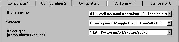
53 Siemens Technical Manual 998 3/3


54 3/32 Siemens Technical Manual 998

55 Input edge evalution communication object RAMmemory unit send condition on change at input send condition: cyclic sending t bus 2EM )XQFWLRQ 2EMHFWÃQDPH 7\SH )ODJ,QSXWÃ$ 2QRIIWRJJOH ELW &:78 VHQGLQJ 7KLVÃREMHFWÃKROGVÃWKHÃJURXSÃDGGUHVVÃWRÃVHQGLQJÃWKHÃVZLWFKLQJ WHOHJUDPVÃRIÃLQSXWÃ$Ã7KHÃSDUDPHWHUÃÅ(GJHÃHYDOXDWLRQÅÃUXOHV ZKLFKÃVLJQDOÃVWDWHÃZLOOÃSURGXFHÃWKHÃÅRQÅÃWHOHJUDPVÃDQGÃZKLFK RQHÃZLOOÃSURGXFHÃWKHÃÅRIIÅÃWHOHJUDPVÃ:KHQÃVHWÃWRÃÅWRJJOHÅÃDOO JURXSÃDGGUHVVHVÃWRÃFHQWUDOÃVZLWFKLQJÃWHOHJUDPVÃWKDWÃZHUH DVVLJQHGÃWRÃWKHÃDFWXDWRUÃPXVWÃDOVRÃEHÃDGGHGÃWRÃV\QFKURQL]LQJ WKHÃSXVKÃEXWWRQÃVHQVRU,QSXWÃ% 2QRIIWRJJOH ELW &:78 VHQGLQJ 7KLVÃREMHFWÃKROGVÃWKHÃJURXSÃDGGUHVVÃWRÃVHQGLQJÃWKHÃVZLWFKLQJ WHOHJUDPVÃRIÃLQSXWÃ%Ã7KHÃSDUDPHWHUÃÅ(GJHÃHYDOXDWLRQÅÃUXOHV ZKLFKÃVLJQDOÃVWDWHÃZLOOÃSURGXFHÃWKHÃÅRQÅÃWHOHJUDPVÃDQGÃZKLFK RQHÃZLOOÃSURGXFHÃWKHÃÅRIIÅÃWHOHJUDPVÃ:KHQÃVHWÃWRÃÅWRJJOHÃÅÃDOO JURXSÃDGGUHVVHVÃWRÃFHQWUDOÃVZLWFKLQJÃWHOHJUDPVÃWKDWÃZHUH DVVLJQHGÃWRÃWKHÃDFWXDWRUÃPXVWÃDOVRÃEHÃDGGHGÃWRÃV\QFKURQL]LQJ WKHÃSXVKÃEXWWRQÃVHQVRU,QSXWÃ& 2QRIIWRJJOH ELW &:78 VHQGLQJ 7KLVÃREMHFWÃKROGVÃWKHÃJURXSÃDGGUHVVÃWRÃVHQGLQJÃWKHÃVZLWFKLQJ WHOHJUDPVÃRIÃLQSXWÃ&Ã7KHÃSDUDPHWHUÃÅ(GJHÃHYDOXDWLRQÅÃUXOHV ZKLFKÃVLJQDOÃVWDWHÃZLOOÃSURGXFHÃWKHÃÅRQÅÃWHOHJUDPVÃDQGÃZKLFK RQHÃZLOOÃSURGXFHÃWKHÃÅRIIÅÃWHOHJUDPVÃ:KHQÃVHWÃWRÃÅWRJJOHÃÅÃDOO JURXSÃDGGUHVVHVÃWRÃFHQWUDOÃVZLWFKLQJÃWHOHJUDPVÃWKDWÃZHUH DVVLJQHGÃWRÃWKHÃDFWXDWRUÃPXVWÃDOVRÃEHÃDGGHGÃWRÃV\QFKURQL]LQJ WKHÃSXVKÃEXWWRQÃVHQVRU,QSXWÃ' 2QRIIWRJJOH ELW &:78 VHQGLQJ 7KLVÃREMHFWÃKROGVÃWKHÃJURXSÃDGGUHVVÃWRÃVHQGLQJÃWKHÃVZLWFKLQJ WHOHJUDPVÃRIÃLQSXWÃ'Ã7KHÃSDUDPHWHUÃÅ(GJHÃHYDOXDWLRQÅÃUXOHV ZKLFKÃVLJQDOÃVWDWHÃZLOOÃSURGXFHÃWKHÃÅRQÅÃWHOHJUDPVÃDQGÃZKLFK RQHÃZLOOÃSURGXFHÃWKHÃÅRIIÅÃWHOHJUDPVÃ:KHQÃVHWÃWRÃÅWRJJOHÃÅÃDOO JURXSÃDGGUHVVHVÃWRÃFHQWUDOÃVZLWFKLQJÃWHOHJUDPVÃWKDWÃZHUH DVVLJQHGÃWRÃWKHÃDFWXDWRUÃPXVWÃDOVRÃEHÃDGGHGÃWRÃV\QFKURQL]LQJ WKHÃSXVKÃEXWWRQÃVHQVRU Siemens Technical Manual 998 3/9


56 3DUDPHWHUV 6HWWLQJV 'HERXQFHÃWLPH ÃPLOOLVHFRQGV ÃPLOOLVHFRQGV ÃPLOOLVHFRQGV ÃPLOOLVHFRQGV $ÃEULHIÃERXQFLQJÃRFFXUVÃHDFKÃWLPHÃDÃSXVKÃEXWWRQÃLVÃRSHUDWHG 7KHÃFRQWDFWÃRSHQVÃDQGÃFORVHVÃDÃFRXSOHÃRIÃWLPHVÃEHIRUH VHWWOLQJÃLQÃWKHÃFORVHGÃSRVLWLRQÃ7KHÃERXQFLQJÃWLPHÃGHSHQGV RQÃWKHÃSXVKÃEXWWRQÃXVHGÃ7RÃDYRLGÃWKHÃVHQGLQJÃRIÃPXOWLSOH VZLWFKLQJÃWHOHJUDPVÃDVÃDÃUHVSRQVHÃWRÃWKHÃPXOWLSOHÃVZLWFK RSHUDWLRQVÃFDXVHGÃE\ÃUHDGLQJÃWKHÃLQSXWÃGXULQJÃWKHÃERXQFLQJ WLPHÃWKHÃGHERXQFHÃWLPHÃVKRXOGÃEHÃVHOHFWHGÃDFFRUGLQJÃWRÃWKH SXVKÃEXWWRQVÃFKDUDFWHULVWLFÃ2QÃUHDGLQJÃDÃFKDQJHÃRIÃLQSXW VWDWHÃWKHÃDSSOLFDWLRQÃSURJUDPÃZDLWVÃWRÃWKHÃVSHFLILHGÃSHULRGÃRI WLPHÃEHIRUHÃSURFHVVLQJÃWKHÃDFWXDOÃVWDWH 6HQGÃFXUUHQWÃYDOXHÃRQÃEXV YROWDJHÃUHVWRUDWLRQÃDV UXOHGÃE\ÃHGJHÃHYDOXDWLRQ <HV R 2QÃEXVÃYROWDJHÃUHVWRUDWLRQÃDQGÃRQÃLQLWLDOL]LQJÃWKHÃELQDU\ÃLQSXW WKHÃVLJQDOÃVWDWHVÃRIÃWKHÃLQSXWVÃDUHÃUHDGÃDVÃUXOHGÃE\ÃWKHÃÅHGJH HYDOXDWLRQÅÃSDUDPHWHUÃDQGÃVHQWÃRQÃWKHÃEXVÃZLWKÃDÃGHOD\ÃRI DSSUR[ÃÃVHFRQGVÃDFFRUGLQJÃWRÃWKHÃVHWWLQJÃRIÃWKHÃSDUDPHWHU Å6HQGÃRQÃFKDQJHÃDWÃLQSXWÃDQGÃRQÃEXVÃYROWDJHÃUHVWRUDWLRQÅ :KHQÃVHWÃWRÃÅULVLQJÃHGJHÅÃDÃORJLFDOÃÅÅÃVLJQDOÃVWDWHÃLVÃUHTXLUHG WRÃVHQGLQJÃDQGÃDÃORJLFDOÃÅÅÃZKHQÃVHWÃWRÃÅIDOOLQJÃHGJHÅ Å<HVÅÃ7KHÃVLJQDOÃVWDWHVÃDWÃWKHÃLQSXWVÃDUHÃVHQWÃRQÃEXVÃYROWDJH UHVWRUDWLRQ ÅRÅÃ7KHÃVLJQDOÃVWDWHVÃDWÃWKHÃLQSXWVÃDUHÃQRWÃVHQWÃRQÃEXV YROWDJHÃUHVWRUDWLRQ 7HOHJUDPÃUDWHÃOLPLW GLVDEOHG HQDEOHG 7HOHJUDPÃUDWHÃOLPLW ÃWHOHJUDPVÃSHUÃÃVHF ÃWHOHJUDPVÃSHUÃÃVHF ÃWHOHJUDPVÃSHUÃÃVHF ÃWHOHJUDPVÃSHUÃÃVHF 7KLVÃSDUDPHWHUÃDOORZVÃ\RXÃWRÃOLPLWÃWKHÃQXPEHUÃRIÃWHOHJUDPV WKDWÃFDQÃEHÃVHQWÃLQÃDÃJLYHQÃSHULRGÃRIÃWLPHÃWRÃDYRLGÃEXV RYHUORDGÃFDXVHGÃE\ÃH[FHVVÃWHOHJUDPVÃIURPÃPDOIXQFWLRQLQJ SXVKÃEXWWRQV 7HOHJUDPÃUDWHÃOLPLWÃÅGLVDEOHGÅÃ7KHUHÃLVÃQRÃOLPLWÃWRÃVHQGLQJ WHOHJUDPV 7HOHJUDPÃUDWHÃOLPLWÃÅHQDEOHGÅÃ$ÃPD[LPXPÃRIÃHLWKHUÃÃ ÃRUÃÃWHOHJUDPVÃFDQÃEHÃVHQWÃSHUÃÃVHFRQGÃSHULRG 3DUDPHWHUV (GJHÃHYDOXDWLRQ 6HWWLQJV ULVLQJÃRQÃIDOOLQJÃRII ULVLQJÃRIIÃIDOOLQJÃRQ ULVLQJÃRQ IDOOLQJÃRQ ULVLQJÃRII IDOOLQJÃRII ULVLQJÃWRJJOH IDOOLQJÃWRJJOH ULVLQJÃWRJJOHÃIDOOLQJÃWRJJOH QRÃHYDOXDWLRQ 7KLVÃSDUDPHWHUÃGHILQHVÃWKHÃVZLWFKLQJÃVWDWHÃWKDWÃLVÃWRÃEH ZULWWHQÃWRÃWKHÃFRPPXQLFDWLRQÃREMHFWÃRQÃDQÃDSSURSULDWH FKDQJHÃRIÃVLJQDOÃVWDWHÃDWÃWKHÃLQSXW 7KHÃULVLQJÃHGJHÃLVÃDÃFKDQJHÃRIÃWKHÃVLJQDOÃVWDWHÃIURPÃORJLFDOÃÅÅ WRÃÅÅÃWKHÃIDOOLQJÃHGJHÃLVÃDÃFKDQJHÃIURPÃORJLFDOÃÅÅÃWRÃÅÅ ÅULVLQJÃRQÃIDOOLQJÃRIIÅÃ2QÃDÃULVLQJÃHGJHÃDÃORJLFDOÃÅÅÃLVÃZULWWHQ WRÃWKHÃFRPPXQLFDWLRQÃREMHFWÃRQÃDÃIDOOLQJÃHGJHÃDÃORJLFDOÃÅÅÃLV ZULWWHQ ÅULVLQJÃRIIÃIDOOLQJÃRQÅÃ2QÃDÃULVLQJÃHGJHÃDÃORJLFDOÃÅÅÃLVÃZULWWHQ WRÃWKHÃFRPPXQLFDWLRQÃREMHFWÃRQÃDÃIDOOLQJÃHGJHÃDÃORJLFDOÃÅÅÃLV ZULWWHQ ÅULVLQJÃRQÅÃ2QÃDÃULVLQJÃHGJHÃDÃORJLFDOÃÅÅÃLVÃZULWWHQÃWRÃWKH FRPPXQLFDWLRQÃREMHFWÃIDOOLQJÃHGJHVÃDUHÃLJQRUHG ÅIDOOLQJÃRQÅÃ2QÃDÃIDOOLQJÃHGJHÃDÃORJLFDOÃÅÅÃLVÃZULWWHQÃWRÃWKH FRPPXQLFDWLRQÃREMHFWÃULVLQJÃHGJHVÃDUHÃLJQRUHG ÅULVLQJÃRIIÅÃ2QÃDÃULVLQJÃHGJHÃDÃORJLFDOÃÅÅÃLVÃZULWWHQÃWRÃWKH FRPPXQLFDWLRQÃREMHFWÃIDOOLQJÃHGJHVÃDUHÃLJQRUHG ÅIDOOLQJÃRIIÅÃ2QÃDÃIDOOLQJÃHGJHÃDÃORJLFDOÃÅÅÃLVÃZULWWHQÃWRÃWKH FRPPXQLFDWLRQÃREMHFWÃULVLQJÃHGJHVÃDUHÃLJQRUHG ÅULVLQJÃWRJJOHÅÃ2QÃDÃULVLQJÃHGJHÃWKHÃREMHFWÃVWDWHÃLVÃLQYHUWHG LHÃDÃORJLFDOÃÅÅÃEHFRPHVÃDÃORJLFDOÃÅÅÃDQGÃYLFHÃYHUVDÃ,HÃRQ WKHÃILUVWÃHGJHÃFKDQJHÃDÃORJLFDOÃÅÅÃLVÃZULWWHQÃRQÃWKHÃQH[WÃHGJH FKDQJHÃDÃÅÅÃHWFÃ)DOOLQJÃHGJHVÃDUHÃLJQRUHG ÅIDOOLQJÃWRJJOHÅÃ2QÃDÃIDOOLQJÃHGJHÃWKHÃREMHFWÃVWDWHÃLVÃLQYHUWHG LHÃDÃORJLFDOÃÅÅÃEHFRPHVÃDÃORJLFDOÃÅÅÃDQGÃYLFHÃYHUVDÃ,HÃRQ WKHÃILUVWÃHGJHÃFKDQJHÃDÃORJLFDOÃÅÅÃLVÃZULWWHQÃRQÃWKHÃQH[WÃHGJH FKDQJHÃDÃÅÅÃLVÃZULWWHQÃHWFÃ5LVLQJÃHGJHVÃDUHÃLJQRUHG ÅULVLQJÃWRJJOHÃIDOOLQJÃWRJJOHÅÃ2QÃHYHU\ÃHGJHÃFKDQJHÃIURPÃÅÅ WRÃÅÅÃDQGÃIURPÃÅÅÃWRÃÅÅÃWKHÃREMHFWÃVWDWHÃLVÃLQYHUWHGÃ,HÃRQ WKHÃILUVWÃHGJHÃFKDQJHÃDÃORJLFDOÃÅÅÃLVÃZULWWHQÃRQÃWKHÃQH[WÃHGJH FKDQJHÃDÃÅÅÃLVÃZULWWHQÃHWF ÅÃQRÃHYDOXDWLRQÃÅÃ&KDQJHVÃRIÃWKHÃVLJQDOÃHGJHÃDWÃWKHÃLQSXWÃGR QRWÃFKDQJHÃWKHÃREMHFWÃVWDWHÃ7KHÃVZLWFKLQJÃVWDWHÃRIÃWKH FRPPXQLFDWLRQÃREMHFWÃFDQÃRQO\ÃEHÃFKDQJHGÃE\ÃEXV WHOHJUDPV 3/92 Siemens Technical Manual 998
57 Siemens Technical Manual 998 3/93 3DUDPHWHUV 6HWWLQJV 6HQGÃFRQGLWLRQVÃVHQGÃRQ FKDQJHÃDWÃLQSXWÃRUÃRQÃEXV YROWDJHÃUHVWRUDWLRQ ULVLQJÃDQGÃIDOOLQJÃHGJH ULVLQJÃHGJH IDOOLQJÃHGJH QRÃVHQGLQJ 7KLVÃSDUDPHWHUÃUXOHVÃZKHWKHUÃWHOHJUDPVÃDUHÃVHQWÃRQÃDÃFKDQJH RIÃWKHÃVLJQDOÃHGJHÃDWÃWKHÃLQSXWÃDQGÃRQÃEXVÃYROWDJHÃUHVWRUDWLRQ ZLWKÃDQÃDSSURSULDWHÃLQSXWÃVLJQDOÃ7KHÃVZLWFKLQJÃVWDWHVÃWRÃÅRQÅ DQGÃÅRIIÅÃWHOHJUDPVÃFDQÃEHÃGHILQHGÃZLWKÃWKHÃSDUDPHWHUÃÅ(GJH HYDOXDWLRQÅÃ7KHÃULVLQJÃHGJHÃLVÃDÃFKDQJHÃRIÃWKHÃVLJQDOÃVWDWH IURPÃORJLFDOÃÅÅÃWRÃÅÅÃDQGÃDÃÅÅÃVLJQDOÃVWDWHÃDWÃWKHÃLQSXWÃRQÃEXV YROWDJHÃUHVWRUDWLRQÃ7KHÃIDOOLQJÃHGJHÃLVÃDÃFKDQJHÃRIÃWKHÃVLJQDO VWDWHÃIURPÃORJLFDOÃÅÅÃWRÃÅÅÃDQGÃDÃÅÅÃVLJQDOÃVWDWHÃDWÃWKHÃLQSXW RQÃEXVÃYROWDJHÃUHVWRUDWLRQ ÅULVLQJÃDQGÃIDOOLQJÃHGJHÅÃ2QÃHYHU\ÃHGJHÃFKDQJHÃIURPÃÅÅÃWRÃÅÅ DQGÃIURPÃÅÅÃWRÃÅÅÃDQGÃRQÃEXVÃYROWDJHÃUHVWRUDWLRQÃZLWKÃHLWKHU VLJQDOÃVWDWHÃDWÃWKHÃLQSXWÃDÃWHOHJUDPÃLVÃVHQW ÅULVLQJÃHGJHÅÃ2QÃHYHU\ÃULVLQJÃHGJHÃDWÃWKHÃLQSXWÃDÃWHOHJUDPÃLV VHQWÃIDOOLQJÃHGJHVÃDUHÃLJQRUHGÃ2QÃEXVÃYROWDJHÃUHVWRUDWLRQÃD WHOHJUDPÃLVÃVHQWÃRQO\ÃZLWKÃDÃORJLFDOÃÅÅÃDWÃWKHÃLQSXW ÅIDOOLQJÃHGJHÅÃ2QÃHYHU\ÃIDOOLQJÃHGJHÃDWÃWKHÃLQSXWÃDÃWHOHJUDPÃLV VHQWÃULVLQJÃHGJHVÃDUHÃLJQRUHGÃ2QÃEXVÃYROWDJHÃUHVWRUDWLRQÃD WHOHJUDPÃLVÃVHQWÃRQO\ÃZLWKÃDÃORJLFDOÃÅÅÃDWÃWKHÃLQSXW ÅQRÃVHQGLQJÅÃRÃWHOHJUDPVÃDUHÃVHQWÃRQÃFKDQJHVÃRIÃWKHÃVLJQDO HGJHÃDWÃWKHÃLQSXWÃRUÃRQÃEXVÃYROWDJHÃUHVWRUDWLRQ 6HQGÃFRQGLWLRQÃF\FOLFÃVHQG QRÃF\FOLFÃVHQGLQJ F\FOLFÃRQÃRQO\ F\FOLFÃRII F\FOLFÃRQÃDQGÃRII 7KLVÃSDUDPHWHUÃUXOHVÃZKHWKHUÃVZLWFKLQJÃYDOXHVÃRIÃWKH FRPPXQLFDWLRQÃREMHFWÃWRÃEHÃVHQWÃRQÃWKHÃEXVÃZLWKÃWKH VSHFLILHGÃF\FOLFÃVHQGÃIUHTXHQF\ ÅQRÃF\FOLFÃVHQGLQJÅÃ7HOHJUDPVÃDUHÃQRWÃVHQWÃF\FOLFDOO\ ÅF\FOLFÃRQÃRQO\ÅÃ2QO\ÃDÃORJLFDOÃÅÅÃREMHFWÃVWDWHÃLVÃVHQWÃF\FOLFDOO\ RQÃWKHÃEXVÃ7KHÃF\FOLFÃVHQGLQJÃHQGVÃRQÃFKDQJHÃRIÃWKHÃVLJQDO HGJHÃDWÃWKHÃLQSXWÃRUÃRQÃUHFHLYLQJÃDÃEXVÃWHOHJUDPÃWRÃFKDQJH IURPÃÅÅÃWRÃÅÅ ÅF\FOLFÃRIIÃRQO\ÅÃ2QO\ÃDÃORJLFDOÃÅÅÃREMHFWÃVWDWHÃLVÃVHQW F\FOLFDOO\ÃRQÃWKHÃEXVÃ7KHÃF\FOLFÃVHQGLQJÃHQGVÃRQÃFKDQJHÃRI WKHÃVLJQDOÃHGJHÃDWÃWKHÃLQSXWÃRUÃRQÃUHFHLYLQJÃDÃEXVÃWHOHJUDPÃWR FKDQJHÃIURPÃÅÅÃWRÃÅÅ ÅF\FOLFÃRQÃDQGÃRIIÅÃ%RWKÃVZLWFKLQJÃVWDWHVÃDUHÃVHQWÃRQÃWKHÃEXV F\FOLFDOO\Ã2QÃFKDQJHÃRIÃWKHÃVLJQDOÃHGJHÃDWÃWKHÃLQSXWÃRUÃRQ UHFHLYLQJÃDQÃDSSURSULDWHÃEXVÃWHOHJUDPÃWKHÃQHZÃVWDWHÃLVÃVHQW F\FOLFDOO\ &\FOLFÃVHQGÃEDVHÃYDOXH WLPHUÃEDVHÃÃVHFRQGV WLPHUÃEDVHÃÃPV WLPHUÃEDVHÃÃPV WLPHUÃEDVHÃÃPV WLPHUÃEDVHÃÃVHFRQGV WLPHUÃEDVHÃÃVHFRQGV WLPHUÃEDVHÃÃVHFRQGV WLPHUÃEDVHÃÃVHFRQGV WLPHUÃEDVHÃÃVHFRQGV WLPHUÃEDVHÃÃPLQ WLPHUÃEDVHÃÃPLQ WLPHUÃEDVHÃÃPLQ WLPHUÃEDVHÃÃPLQ WLPHUÃEDVHÃÃPLQ WLPHUÃEDVHÃÃPLQ WLPHUÃEDVHÃÃK 3DUDPHWHUV 6HWWLQJV &\FOLFÃVHQGÃIDFWRUÃ 7KLVÃSDUDPHWHUÃUXOHVÃWKHÃIUHTXHQF\ÃWRÃF\FOLFÃVHQGLQJ WHOHJUDPVÃRQÃWKHÃEXVÃ7KHÃF\FOLFÃVHQGÃIUHTXHQF\ÃLVÃJHQHUDWHG E\ÃPXOWLSO\LQJÃWKHÃVSHFLILHGÃEDVHÃZLWKÃWKHÃVHOHFWHGÃIDFWRU :KHQÃWKHÃF\FOLFÃVHQGLQJÃLVÃGLVDEOHGÃWKHVHÃSDUDPHWHUVÃDUH LJQRUHG RWHÃ$VÃWKHÃVSHFLILHGÃEDVHÃHTXDOVÃWKHÃPD[LPXPÃWLPLQJ HUURUÃWKHÃVPDOOHVWÃSRVVLEOHÃEDVHÃVKRXOGÃEHÃXVHGÃWRÃHVWDEOLVK WKHÃGHVLUHGÃIUHTXHQF\ Object value on off on off off on Input signal bus Object value off off off Input signal bus Object value off Input signal bus on on on off off on off
58 Input signal Object value bus off off off on off off off on Input signal Object value bus on on on on on on on on on on 3/94 Siemens Technical Manual 998

59 Application program descriptions June 22 2 S2 Brightness and Temperature 22C Application program usage Product family: Product type: Manufacturer: Name: Order-No.: Functional description Physical sensors Brightness and Temperature Siemens Dual Sensor for Brightness and Temperature AP 254 5WG 254-3EY The Dual Sensor AP 254 provides ambient light level and outdoor temperature values. These values can be sent onto the bus. Further the device controls load switches, dimmers and blinds / shutters based on threshold settings for ambient light level and outdoor temperature: Threshold setting for light level controls Threshold setting for temperature controls Threshold setting for shading controls (combination of light level and temperature) Additionally one or more thresholds can be temporarily deactivated via an interlocking object ( Bit). Communication objects Obj Object name Function Type Flag Brightness value Lux-value 2 Byte KÜ (EIS 5) Depending on the parameters set, it sends the current value of brightness cyclically and/or upon a change of brightness. Temperature C-value (EIS 5) 2 Byte KÜ Depending on the parameters set, it sends the current temperature value cyclically and/or upon a change of temperature. 3 Brightness threshold / Bit KÜ 8-bit Value (EIS 6) Byte KÜ 4 Brightness threshold 2 / Bit KÜ 5 Brightness threshold 3 / Bit KÜ The parameterized telegram is sent if the value exceeds or falls below the set threshold value. Important: Threshold (Object 3) can also be parameterized as an automatic brightness control: Dimming are sent until the brightness measured has reached the setpoint value. Constant light level control is performed within the parameterized hysteresis. 6 Temperature threshold / Bit KÜ 7 Temperature threshold 2 / Bit KÜ The parameterized telegram is sent if the value exceeds or falls below the set threshold value. 8 Logic function / Bit KÜ 9 Logic function 2 / Bit KÜ The parameterized telegram is sent if the value exceeds or falls below the set threshold value. Blocking =normal / =blocked Bit KLSÜ Via this -bit object sending of each single object can be blocked (Blocking=) or released (Blocking=). The parameters are set on the parameter tabs for the object to be blocked. Note When the Blocking object is set to normal then each object that was blocked immediately sends its current value. In case of bus voltage failure the Blocking object is set to the value of. Note Your screen presentation may vary from these typical snap shots. Note The value of a communication object is only initialized or updated when sending based on an event. A visualization should not read the value of these objects. Siemens AG 22C, 6 pages Technical manual Electrical Installation Technology Siemens AG 22 Update: Subject to change without further notice /


60 Application program descriptions June 22 2 S2 Brightness and Temperature 22C Maximum number of group addresses: 5 Maximum number of assignments: 5 Parameter General Parameter Number of brightness brightness threshold thresholds 2 brightness thresholds 3 brightness thresholds Setting defining how many thresholds shall be used. Function of brightness Brightness threshold threshold automatic brightness control Setting defining whether brightness threshold shall be used as a threshold switch or as an automatic brightness control. IMPORTANT: If threshold is used as an automatic brightness control it can no longer be included in a logic function! Number of No temperature thresholds temperature thresholds temperature threshold 2 temperature thresholds Setting defining if and how many temperature thresholds shall be used. Number of logic function objects No logic operation logic function object 2 logic function objects Setting defining if and how many logic function objects shall be used. Brightness value Parameter Minimal change of brightness to transmit a new value No sending on change 5% min. lux % min. lux 2% min. lux 3% min. lux Setting defining by what percentage the measured new brightness value must deviate from the brightness value sent last to be sent again. Parameter Interval for cyclical sending No cyclical sending minute 3 minutes 5 minutes minutes 2 minutes 3 minutes 45 minutes 6 minutes Setting of the interval at which the brightness value is sent repeatedly to the bus. Note If both no sending on change and no cyclical sending are selected then sending is not performed. Temperature value Note If both no sending on change and no cyclical sending are selected then sending is not performed. Parameter Minimal change of temperature to transmit a new value No sending on change on change K on change of 2K on change of 3K Setting defining by what value the measured new temperature value must deviate from the temperature value sent last to be sent again. Interval for cyclical sending No cyclical sending minute 3 minutes 5 minutes minutes 2 minutes 3 minutes 45 minutes 6 minutes Setting of the cycle interval at which the telegram is repeatedly sent via the bus. Technical manual 22C, 6 pages Siemens AG Update: Siemens AG 22 Electrical Installation Technology Subject to change without further notice /2
 Enables a correction of the temperature measured if this temperature deviates from the true temperature due to the position of the device. The correction is performed in steps of. degrees i.e. from -2,8 to +2,7K.")

61 Application program descriptions June 22 2 S2 Brightness and Temperature 22C Parameter Temperature offset in,k ( ) Enables a correction of the temperature measured if this temperature deviates from the true temperature due to the position of the device. The correction is performed in steps of. degrees i.e. from -2,8 to +2,7K. Example: The value 5 corresponds to a correction of.5 degrees. The value equals degree. In the latter case the device will send the following value when it measures a temperature of 2 C: 2 + = 2 C. Automatic brightness control Parameter Control speed Slow Medium Fast This parameter determines how fast the automatic brightness control reaches the set point. Note: The setting fast can lead to over-shooting of the control loop set point. Interval for cyclical sending minute 3 minutes 5 minutes minutes 2 minutes 3 minutes 45 minutes 6 minutes Setting of the cycle interval at which the telegram is repeatedly sent via the bus. Behaviour if blocking Blocking disable object is ON blocking enable If the Blocking object is set to = blocking and this parameter is set to blocking enable then sending for this object is inhibited. Parameter Set point for brightness control in Lux Setting of the set point for automatic brightness control. Permissible set point values are 2 to 25 Lux, where the set point is entered as * Lux. Hysteresis % min. lux 2% min. lux 3% min. lux 5% min. lux The hysteresis suppresses sending if the measured brightness value is in the range [set point ; set point plus hysteresis]. The hysteresis is defined as the maximum of x% (x=, 2, 3 or 5) of the set point or Lux. Limit number of for automatic control Max. 2 per second Max. telegram per second max. telegram in 2 seconds This parameter limits the number of control to reduce the bus load. Brightness threshold (2,3) Function and parameters for Brightness thresholds, 2 and 3 are identical and described once only. Parameter Threshold 2. 5 lux. lux Setting at which brightness level the switching threshold has been reached. Siemens AG 22C, 6 pages Technical manual Electrical Installation Technology Siemens AG 22 Update: Subject to change without further notice /3

62 Application program descriptions June 22 2 S2 Brightness and Temperature 22C Parameter Hysteresis % min. lux 2% min. lux 3% min. lux 5% min. lux The hysteresis suppresses sending if the measured brightness level is in the range [set point minus hysteresis; set point]. A threshold overflow is detected when the measured brightness value rises above the threshold. A threshold underflow is detected when the measured brightness value falls under [threshold minus hysteresis]. The hysteresis is the maximum of x% (x=, 2, 3 or 5) of the threshold or Lux. Delay above threshold Undelayed 2 seconds... (5,, 5, 2 seconds) 3 seconds... (45, 6, 9 seconds)... (2, 3, 5,, 5 minutes) 3 minutes Delay between detection of a threshold overflow and the reaction to it (sending a telegram). It prevents false switching because of luminous reflectance or transient shading. Recommendation: Lighting control 2...6s Shading device min Delay below threshold Undelayed 2 seconds... (5,, 5, 2, 3 seconds) 45 seconds 6 seconds 9 seconds... (2, 3, 5,, 5 minutes) 3 minutes Delay between detection of a threshold underflow and the reaction to it (sending a telegram). It prevents false switching because of luminous reflectance or transient shading. Recommendation: Lighting control 2...6s Shading device min Note: To avoid false switching the device is designed with a delay in case of a threshold underflow. The base delay is always present and cannot be changed by this parameter. Brightness object (2,3) Function and parameters for Brightness objects, 2 and 3 are identical and described once only. Parameter Function of threshold object Switch Send value The type of telegram that shall be sent. Switch on/ switch off telegram or value ( ). Behaviour above threshold Do not send any send telegram only once send telegram cyclically send no value send value only once cyclical sending Setting defining if and how often a telegram shall be sent in case of threshold overflow. Telegram Switch off switch on Value [ ] Setting defining what shall be sent in case of threshold overflow. Behaviour below threshold Do not send any send only once cyclical sending send no value send value only once send value cyclically Setting defining if and how often a telegram shall be sent in case of threshold underflow. Telegram Switch off switch on Value [ ] Setting defining what shall be sent in case of threshold underflow. Technical manual 22C, 6 pages Siemens AG Update: Siemens AG 22 Electrical Installation Technology Subject to change without further notice /4

63 Application program descriptions June 22 2 S2 Brightness and Temperature 22C Parameter Interval for cyclical sending minute 3 minutes 5 minutes minutes 2 minutes 3 minutes 45 minutes 6 minutes Setting of the cycle interval at which the telegram is repeatedly sent via the bus. Behaviour if blocking Blocking disable object is ON blocking enable If the Blocking object is set to = blocking and this parameter is set to blocking enable then sending for this object is inhibited. Temperature threshold (2) Function and parameters for Temperature threshold, 2 and 3 are identical and described once only. Parameter Threshold value in C 5 [-5..5] Setting of the temperature threshold. Hysteresis K 2 K 3K 4K The hysteresis suppresses sending if the measured temperature is in the range [set point minus hysteresis; set point]. A threshold overflow is detected when the measured temperature rises above the threshold. A threshold underflow is detected when the measured temperature falls under [threshold minus hysteresis]. The hysteresis is the maximum of x% (x=, 2, 3 or 5) of the threshold or Lux. Function of threshold object Switch send value Parameter The type of telegram to be sent: Switch on/switch off telegram or value ( ) Behaviour above threshold Do not send any send telegram only once send telegram cyclically send no value send value only once cyclical sending Setting defining if and how often a telegram shall be sent in case of threshold overflow. Telegram Switch off switch on Value [ ] Setting defining what shall be sent in case of threshold overflow. Behaviour below threshold Do not send any send telegram only once send telegram cyclically send no value send value only once cyclical sending Setting defining if and how often a telegram shall be sent in case of threshold underflow. Telegram Switch off switch on Value [ ] Setting defining what shall be sent in case of threshold underflow. Interval for cyclical sending minute 3 minutes 5 minutes minutes 2 minutes 3 minutes 45 minutes 6 minutes Setting of the cycle interval at which the telegram is repeatedly sent via the bus. Behaviour if blocking Blocking disable object is ON blocking enable If the Blocking object is set to = blocking and this parameter is set to blocking enable then sending for this object is inhibited. Siemens AG 22C, 6 pages Technical manual Electrical Installation Technology Siemens AG 22 Update: Subject to change without further notice /5


64 Application program descriptions June 22 2 S2 Brightness and Temperature 22C Logic function (2) Function and parameters for Logic functions and 2 are identical and described once only. Parameter If brightness is not evaluated higher than brightness threshold higher than brightness threshold 2 higher than brightness threshold 3 lower than brightness threshold lower than brightness threshold 2 lower than brightness threshold 3 First part of logic function: What shall the brightness value be to fulfil the logic function condition? Important note: If the Brightness threshold is used for automatic brightness control then it shall not be used in the logic functions! and if temperature is not evaluated higher than temperature threshold higher than temperature threshold 2 higher than temperature threshold 3 lower than temperature threshold lower than temperature threshold 2 lower than temperature threshold 3 second part of logic function: What shall the temperature value be to fulfil the logic function condition together with the brightness value? Logic object (2) Parameter Function of the logic object Switch send value Type of the telegram which is to be sent; switching / telegram or value ( ) Behaviour if logic operation is true Do not send any send telegram only once send telegram cyclically send no value send value only once cyclical sending Setting defining if and how often a telegram shall be sent in case the logic operation is true. Telegram Switch off switch on Value [ ] Setting defining what shall be sent in case the logic function result is true. Behaviour if logic operation is false Do not send any send telegram only once send telegram cyclically send no value send value only once cyclical sending Setting defining if and how often a telegram shall be sent in case the logic operation is false. Telegram Switch off switch on Value [ ] Setting defining what shall be sent in case the logic function result is false. Interval for cyclical sending minute 3 minutes 5 minutes minutes 2 minutes 3 minutes 45 minutes 6 minutes Setting of the cycle interval at which the telegram is repeatedly sent via the bus. Behaviour if blocking Blocking disable object is ON blocking enable If the Blocking object is set to = blocking and this parameter is set to blocking enable then sending for this object is inhibited. Function and parameters for Logic function objects and 2 are identical and described once only. Technical manual 22C, 6 pages Siemens AG Update: Siemens AG 22 Electrical Installation Technology Subject to change without further notice /6

65 Application Program Description April 22 S2 Switching, Value, Scene 22D Application program usage Communication objects Product family: Product type: Manufacturer: Timer REG-Devices Siemens Name: 2-channel Time-switch REG 37 Order-No.: 5WG 37-5EY Functional description The 2-channel time switch REG 37 (weekly scheduler) with integrated bus coupling unit is a DIN rail mounted device for mounting in distribution boards. The connection to EIB is made via a bus connector. The time switch offers: 36 schedules, which may be assigned to one, several or all weekdays (free block formation). Additionally, the REG 37 is already set ex factory with the current time and valid Middle European settings for daylight savings time switchover (summer / winter time). If another or no switchover is desired this can be set as described in the operation manual. - Programmed schedules are saved for up to years in case the bus voltage fails and the back-up battery runs low - automatic program review - 99 days holiday program, programmable 99 days in advance - switching pre-select - permanent ON/OFF - Lithium battery backup, approx. 6 years each channel switching, priority and dimming or value messages can be transmitted at pre-set times. Application examples Ideally suited for residential applications and smaller EIB projects Up to four may be sent to the bus when one channel schedule switches (e.g. at the end of a work day: switch off main lighting, close shutters, reduce room temperature, lock perimeter doors) Note Your screen presentation may vary from these typical snap shots. Obj Object name Function Type Flag Channel / Bit KÜ Object A 8-bit Value Byte (EIS 6) Positive drive 2 Bit (EIS 8) Channel KÜ Object B 2 Channel KÜ Object C 3 Channel KÜ Object D 4 Channel 2 / Bit KÜ Object A 8-bit Value Byte (EIS 6) Positive drive 2 Bit (EIS 8) 5 Channel KÜ Object B 6 Channel KÜ Object C 7 Channel 2 Object D KÜ / : Send a switching telegram when scheduler channel or scheduler channel 2 switches. 8-bit Value (EIS 6): Send an 8-bit value (dimming, set value), when scheduler channel or scheduler channel 2 switches. Positive drive (EIS 8): Send an 8-bit value (dimming, set value), when scheduler channel or scheduler channel 2 switches. Siemens AG 22D, 4 pages Technical manual Electrical Installation Technology Siemens AG 22 Update: Subject to change without further notice /
 Object A (B-D) Note Requesting the value of a communication object is not possible.")

66 Application Program Description April 22 S2 Switching, Value, Scene 22D Obj Object name Function Type Flag 8 = normal / = blocked Blocking Bit KSÜ If Blocking is set to = blocked and the parameter for blocking of a channel object is enabled then sending for that channel object is blocked. Switching Channel (2) Object A (B-D) Note Requesting the value of a communication object is not possible. Maximum number of group addresses: Maximum number of assignments: Parameter General Parameter Number of objects for channel object 2 objects 3 objects 4 objects Setting for how many scene objects shall be available for channel. Number of objects for channel 2 object 2 objects 3 objects 4 objects Setting for how many scene objects shall be available for channel 2. Interval for cyclical sending 2,5 minutes 5 minutes minutes 5 minutes 2 minutes 3 minutes 45 minutes 6 minutes Setting of the time interval used for sending repeatedly to the bus. For small time values the real length of the interval may differ slightly from the value set. This parameter applies to all communication objects which are set for cyclical sending. Function and parameters of channels - 2 and the corresponding objects A - D are identical and described only once. Parameter Function switch 8-bit value positive drive Select if a switch ( bit), value (8 bit) or positive drive (2 bit) telegram shall be sent via this scheduler channel. Behaviour if clock switches OFF send telegram do not send any Select if a telegram shall be sent when the clock channel switches off. Switching telegram switch off switch on This parameter appears if a switching telegram shall be sent. Select if a or telegram shall be sent when the clock channel switches off. Behaviour if clock switches ON send telegram do not send any Select if a telegram shall be sent when the clock channel switches on. switching telegram switch off switch on This parameter appears if a switching telegram shall be sent. Select if a or telegram shall be sent when the clock channel switches off. Behaviour of sending cyclical sending no cyclical sending Select if the telegram shall be sent once only or cyclically. Behaviour if blocking object is ON ignore blocking enable blocking If the EIB object Blocking is set to = blocking and this parameter is set to enable blocking then sending for this channel is blocked. Behaviour at the beginning of blocking do not send any send following telegram once This parameter appears if blocking is enabled. It determines the sending behaviour when blocking starts. Technical manual 22D, 4 pages Siemens AG Update: Siemens AG 22 Electrical Installation Technology Subject to change without further notice /2


67 Application Program Description April 22 S2 Switching, Value, Scene 22D Parameter as if clock switches OFF as if clock switches ON This parameter appears if a telegram shall be sent once after blocking starts. 8-bit Value Channel (2) Object A (B D) Parameter Behaviour if blocking object is ON ignore blocking enable blocking If the EIB object Blocking is set to = blocking and this parameter is set to enable blocking then sending for this channel is blocked. Behaviour at the beginning of blocking do not send any send following telegram once This parameter appears if blocking is enabled. It determines the sending behaviour when blocking starts. as if clock switches OFF as if clock switches ON This parameter appears if a telegram shall be sent once after blocking starts. Positive drive Channel (2) Object A (B D) Function and parameters of channels - 2 and the corresponding objects A - D are identical and described only once. Parameter Function switch 8-bit value positive drive Select if a switch ( bit), value (8 bit) or positive drive (2 bit) telegram shall be sent via this scheduler channel. Behaviour if clock switches OFF send telegram do not send any Select if a telegram shall be sent when the clock channel switches off. Value (-255) 5 This parameter appears if a value telegram shall be sent. Select which value telegram shall be sent when the clock channel switches off. Behaviour if clock switches ON send telegram do not send any Select if a telegram shall be sent when the clock channel switches on. Value (-255) 2 This parameter appears if a value telegram shall be sent. Select which value telegram shall be sent when the clock channel switches on. Behaviour of sending cyclical sending no cyclical sending Select if the telegram shall be sent once only or cyclically. Function and parameters of channels - 2 and the corresponding objects A - D are identical and described only once. Parameter Function switch 8-bit value positive drive Select if a switch ( bit), value (8 bit) or positive drive (2 bit) telegram shall be sent via this scheduler channel. Behaviour if clock switches OFF send telegram do not send any Select if a telegram shall be sent when the clock channel switches off. Positive drive disable positive drive switch OFF with positive drive switch ON with positive drive This parameter appears if a positive drive telegram shall be sent. Select which positive drive telegram shall be sent when the clock channel switches off. Siemens AG 22D, 4 pages Technical manual Electrical Installation Technology Siemens AG 22 Update: Subject to change without further notice /3
68 Application Program Description April 22 S2 Switching, Value, Scene 22D Parameter Behaviour if clock switches ON send telegram do not send any Select if a telegram shall be sent when the clock channel switches on. Positive drive disable positive drive switch OFF with positive drive switch ON with positive drive This parameter appears if a positive drive telegram shall be sent. Select which positive drive telegram shall be sent when the clock channel switches on. Behaviour of sending cyclical sending no cyclical sending Select if the telegram shall be sent once only or cyclically. Behaviour if blocking object is ON ignore blocking enable blocking If the EIB object Blocking is set to = blocking and this parameter is set to enable blocking then sending for this channel is blocked. Behaviour at the beginning of blocking do not send any send following telegram once This parameter appears if blocking is enabled. It determines the sending behaviour when blocking starts. as if clock switches OFF as if clock switches ON This parameter appears if a telegram shall be sent once after blocking starts. Positive drive Actuators with positive drive input allow for overriding of outputs via central control commands. E.g. when in energy savings or night operation mode switching on of selected lights or loads can be blocked. In the case of night operation mode a switch OFF positive drive telegram may be sent at 2h and at 6h a switch ON positive drive telegram. Objects Channel A switching positive drive Status Positive drive Bit & & > Relay The positive drive object is a 2-bit object. Bit determines, whether positive drive is active (= ) or passive (= ). If Bit has the value, then positive drive is set to be passive and the switching input value is directly available at the positive drive output. At the same time this value is loaded into Bit of the positive drive object. Thus Bit of the positive drive object always contains the status. If Bit of the positive drive object has the value, then the positive drive is set to be active and the switching input value is irrelevant for the output value. In this case Bit of the positive drive object determines the output of the positive drive. If positive drive is not activated then the switching input value is directly available at the output of the positive drive. Bit Bit Function Positive drive is not activated Positive drive is not activated with positive drive object value with positive drive object value For explanation of positive drive assume a switch actuator with two input objects. The input object switching controls the output dependent on the status of the input positive drive. Technical manual 22D, 4 pages Siemens AG Update: Siemens AG 22 Electrical Installation Technology Subject to change without further notice /4

69 Application Programs Description September 2 2 CO Time 7422 Devices Employing the Program Product family: Product type: Manufacturer: Controller Controller Siemens Name: Timer module N 32 Order-no.: 5WG 32-AB Application Description This application program allows you to make time switch tasks and "on" and "off" delays to switch operations. Four mutually independent channels are available with separate input and output objects each. Furthermore, these channels can be locked and released via an additional locking object. Time switch (staircase lighting mode): When the timer receives a logical "" this is forwarded to the output object according to the switch on delay as specified in the parameter list. Simultaneously, the selected switch off delay is initiated. Each subsequent "" during the delay period re-starts the timer. ce the delay period has passed a logical "" is forwarded to the output object. When receiving a "" during the delay period, it is forwarded to the output immediately cancelling the delay. Output inversion: Output values can be inverted before sending them on the bus. Send condition: The sending filter rules whether only logical ""s or ""s are sent or both output values. Input A INV timer INV send condition Outp. A Communication Objects Input B INV timer INV send condition Outp. B Input C INV timer INV send condition Outp. C Input D INV timer INV send condition Outp. D Verrieg. Input objects INV output objects The following operating modes are available: Input inversion: The values received at the four inputs can be inverted before forwarding them to the corresponding timer. Switch on delay: receiving a logical "" at the timer, the switch on delay is initiated as specified in the parameter list. Each further "" re-starts the timer. ce the delay period has passed, the "" is forwarded to the output object. receiving a logical "" during the delay period the switch on delay is cancelled. Switch off delay: receiving a logical "" at the timer, the switch off delay is initiated as specified in the parameter list. Each further "" re-starts the timer. ce the delay period has passed, the "" is forwarded to the output object. receiving a logical "" during the delay period the switch on delay is cancelled. Note: The order of the entries may vary from the above due to individual customization of the table. Obj Function Object name Type Flag Channel A Input -Bit CWTU Via the group addresses of this input object the switching to timer channel A are received. Channel A Output -Bit CTU Via the group address of this output object the result at the timer channel A is sent. 2 Channel B Input -Bit CWTU Via the group addresses of this input object the switching to timer channel B are received. Siemens AG 7422, 4 pages Technical Manual Electrical Installation Technology Siemens AG 2 Update: /

70 Application Programs Description September 2 2 CO Time 7422 Obj Function Object name Type Flag 3 Channel B Output -Bit CTU Channel A: Via the group address of this output object the result at the timer channel B is sent. 4 Channel C Input -Bit CWTU Via the group addresses of this input object the switching to timer channel C are received. 5 Channel C Output -Bit CTU Via the group address of this output object the result at the timer channel C is sent. 6 Channel D Input -Bit CWTU Via the group addresses of this input object the switching to timer channel D are received. 7 Channel D Output -Bit CTU Via the group address of this output object the result at the timer channel D is sent. 8 Interlocking Channels A-D -Bit CWTU Via the group addresses of the locking object lock/release are received. are provided to specifying individually to each timer channel whether the status of the locking object is to be evaluated. Maximum number of group addresses: 3 Maximum number of assignments: 3 Note: At the bus coupling unit the four output objects share a single memory unit that holds the timer channel result that was received last, the timer channels overwrite each others results. As this is the only information that can be read from an output, the status of a specific output cannot be read. General: Interlocking on object value This parameter rules the object value to enabling/disabling the interlocking mode: "": The locking is enabled with "" and disabled with "". "": The locking is enabled with "" and disabled with "". Send condition on and at output only on at output only on at output This parameter defines a sending filer to sending only on specific status of the output object: "on and at output": Every new object status is sent " only on at output ": ly "" and "off" are sent. When the object status is "" no are sent. " only on at output ": ly "" and "on" are sent. When the object status is "" no are sent. Operating mode Normal mode Time switch This parameter rules switch off delay mode: "Normal mode": receiving an "off" telegram via the switching object, the specified switch off delay is started. Each subsequent "off" telegram received before the period has passed re-starts the delay anew. When the delay period has passed without receiving a further "off" telegram, a "" telegram is sent to the output. "Time switch ": "" received at the timer are forwarded to the output object according to the specified switch on delay. Simultaneously the specified delay is started ignoring any switch on delays. Each subsequent "on" telegram received before the period has passed re-starts the delay anew. When the delay period has passed without receiving a further "on" telegram, a "" telegram is sent to the output. An "off" telegram cancels the switch off delay and is forwarded to the output immediately. Evaluate interlocking object No Yes This parameter rules whether the timer can be locked and released via the locking object or whether the channel is permanently enabled. "No": The timer is permanently enabled. Every input telegram is sent at the output according the specified delay period and sending condition. "Yes": Telegram are sent only if received while the locking object is set to "release". Locking the timer does not cancel any delays that have already been initiated. I.e. are sent according the specified delay period even if the timer is locked before the delay period has passed. Technical Manual 7422, 4 pages Siemens AG Update: Siemens AG 2 Electrical Installation Technology /2
71 Application Programs Description September 2 2 CO Time 7422 Invert output No Yes The timer's output value can be inverted before passing it on to the channel's output object. "No:" The value is passed on to the output object unchanged. "Yes:" The value is inverted before it is passed on to the output object. Invert input No Yes The value received at the channel's input object can be inverted before passing it on to the timer. "No:" The value is passed on to the timer channel unchanged. "Yes:" The value is inverted before it is passed on to the timer channel. Base for delay Time base 3 ms Time base 26 ms Time base 52 ms Time base sec Time base 2, sec Time base 4,2 sec Time base 8,4 sec Time base 7 sec Time base 34 sec Time base, min Time base 2,2 min Time base 4,5 min Time base 9 min Time base 8 min Time base 35 min Time base,2 hr Factor for delay (-27) These parameters rules the delay to switching off. The delay period is generated by multiplying the base with the factor. Factor = "": The switch off delay is disabled. Logical ""s forwarded to the timer is passed on to the output object immediately. Base for delay Time base 3 ms Time base 26 ms Time base 52 ms Time base sec Time base 2, sec Time base 4,2 sec Time base 8,4 sec Time base 7 sec Time base 34 sec Time base, min Time base 2,2 min Time base 4,5 min Time base 9 min Time base 8 min Time base 35 min Time base,2 hr Factor for delay (-27) These parameters rules the delay to switching "on". The delay period is generated by multiplying the specified base with the selected factor. Factor = "": The switch off delay is disabled. Logical ""s forwarded to the timer is passed on to the output object immediately. The below timing diagrams use the parameter setting "Send condition: on and at output". Accordingly only the "off" or "on" would be sent when using the respective settings. The parameters of the channels B to D can be set accordingly. Siemens AG 7422, 4 pages Technical Manual Electrical Installation Technology Siemens AG 2 Update: /3
72 Application Programs Description September 2 2 CO Time 7422 Timing Diagrams: Channel Examples 5. Inverted switching with on and off delay. Non delayed switching without inversion Input on off on off on on off Input on off on on off on off off Eingang time function Input time function Output time function Output time function Output on off off on Output on off on on off on off off 2. Switching with switch on delay and no inversion 6. Timed switching with inversion at the input Input off on off off on off Input Input time function Output time function on off on on off on off Input time function Ausgang time function Output on off on on off off on off Output off on off on off 7. Timed switching with switch on delay and no inversion 3. Switching with switch off delay and no inversion Input Input time function off on off off on off on Input Input time function Output time function on off on on on on Output time function Output on off on off on 4. Switching with on and off delay with no inversion Input on off on off on on off Output off on on off on off 8. Timed switching with no inversion, with interlocking on object value "" interlocking interlocking off on off on Input time function Input on off on on off on Output time function Input time function Output off on on off Output time function Output on on off on off Technical Manual 7422, 4 pages Siemens AG Update: Siemens AG 2 Electrical Installation Technology /4
73 Application program descriptions April 22 7 Event-Schedule-Logic 87 Application program usage Manufacturer: Product family: Product type: Name: Order-No.: Siemens Controller Controller Functional description Event-Schedule-Logic Controller N 35 5WG 35-AB The Event-Schedule-Logic Controller N35 is a DIN rail mounted device. In a compact unit the module offers Event programs, Schedule programs (weekly scheduler) and Logic functions for binary input and output signals. Up to ten event programs are available. For each event program up to ten event actions may be activated. An event program is triggered via an associated event object. The event trigger type may be chosen from this list: Reception of any telegram ( or ) Reception of Reception of Change from to Change from to The value sent ( or ) can be defined per event action. The delay of an event action with respect to the time of the event trigger may also be defined. The weekly scheduler provides a total of schedules for 2 time controlled channels. Each schedule switches a time object on the minute at a pre-defined time on one or several days of the week. The schedules are executed based on a controllerinternal clock which must be synchronized at least once a day with a master time source. The 4-channel time switch REG 372 (order number: 5WG 372-3EY), the 4-channel time switch with DCF77 REG 372/2 (order number: 5WG 372-3EY2), the ISDN gateway N47 (order number: 5WG 47-AB), or the IP Interface AP46 (order number: 5WG 46-3AB) are available as master time clock or time source. at output, is fulfilled then the send filter determines whether any output value or only or only is sent. With the ETS (EIB Tool Software) the application program is selected, its parameters and addresses are assigned appropriately, and downloaded to the Event- Schedule-Logic Controller N 35. Application Examples Indoor and outdoor lighting control applications Lighting control dependent on outdoor light level and weekly schedule (opening hours) Lighting control scenes with dimming in conjunction with a scene controller Timer based lighting control Control of shutters, blinds, and shades Individual schedules for automated comfort (heating, lighting, shading...) Programming for different life styles and user profiles (scene control) Irrigation control / water storage control Garage Door Control Schedule Control examples Every day the lighting of company garage is automatically turned on at 6: and turned off at 22:. Monday through Friday the entrance door lighting of a house is switched on at 8:3 and switched off at 6: Monday through Friday the bed room shutter is raised at 6: and closed at 2:3. Saturday and Sunday it is opened at 8:3 and closed at 22:. Event Control examples Switch lighting of garage on and open motorized garage door but only after authorized entrance. Switch lighting of garage off and close motorized garage door after a specified delay time has passed and the motion detector has signalled an empty space Switch lighting of a house entrance on if the ambient light falls below a certain level (this requires a binary light level detector output) Switch lighting of a house entrance off if the ambient light level rises above a certain level (this requires a binary light level detector output) Ten logic gates, each with up to six inputs and one output, are available. Each gate s logic may be selected from this list: AND, OR, NAND, NOR. Individual logic gate inputs may be inverted. If the configurable send condition, i.e. send on each reception or only on change Siemens AG 87, 6 pages Technical Manual Electrical Installation Technology Siemens AG 2 Update: Postfach 9 53, D-939 Regensburg 3.../
74 Application program descriptions April 22 7 Event-Schedule-Logic 87 Communication objects Obj Function Object name Type Flag Master time clock Date 3 Byte C WTU This object must be connected with the group address for the date sent by the master time clock. The schedule control is not started until date and time are received from the master time clock. Master time clock Time 3 Byte C WTU This object must be connected with the group address for the time sent by the master time clock. The schedule control is not started until date and time are received from the master time clock. 2 / st Schedule Bit C T Object Schedule control for the st schedule control channel is executed via the group address assigned to this st scheduler control object / 2 th Schedule Object Bit C T Schedule control for the 2 th schedule control channel is executed via the group address assigned to this 2 th scheduler control object. 22 Event Tigger st Event Program Bit C WTU The st Event Program is triggered via this object. 23 Event Object - st Event Program Bit C T The st Event Action of the st Event Program is sent to the bus via the group address assigned to this object. 24 Event Object -2 st Event Program Bit C T The 2 nd Event Action of the st Event Program is sent to the bus via the group address assigned to this object Event Object - st Event Program Bit C T The th Event Action of the st Event Program is sent to the bus via the group address assigned to this object. 33 Event Trigger 2 nd Event Program Bit C WTU The 2 nd Event Program is triggered via this object. 34 Event Object 2-2 nd Event Program Bit C T The st Event Action of the 2 nd Event Program is sent to the bus via the group address assigned to this object. 35 Event Object nd Event Program Bit C T The 2 nd Event Action of the 2 nd Event Program is sent to the bus via the group address assigned to this object Event Object 2-2 nd Event Program Bit C T The th Event Action of the 2 nd Event Program is sent to the bus via the group address assigned to this object Event Object - th Event Program Bit C T The th Event Action of the th Event Program is sent to the bus via the group address assigned to this object. 32 Input A st Gate Bit C WTU This is Input A of the st Logic Gate. 33 Input B st Gate Bit C WTU This is Input B of the st Logic Gate. 34 Input C st Gate Bit C WTU This is Input C of the st Logic Gate. 35 Input D st Gate Bit C WTU This is Input D of the st Logic Gate. 36 Input E st Gate Bit C WTU This is Input E of the st Logic Gate. 37 Input F st Gate Bit C WTU This is Input F of the st Logic Gate. 38 Output st Gate Bit C T This is Output of the st Logic Gate. 32 Input A 2 nd Gate Bit C WTU This is Input A of the 2 nd Logic Gate Input F th Gate Bit C WTU This is Input F of the th Logic Gate. 2 Output. Gate Bit C T This is Output of the th Logic Gate. Technical Manual 87, 6 pages Siemens AG Update: Siemens AG 2 Electrical Installation Technology Postfach 9 53, D-939 Regensburg 3.../2

75 Application program descriptions April 22 7 Event-Schedule-Logic 87 Parameter Restart Behavior Parameter Time Parameter Einstellungen Restart delay No delay 2 Seconds 5 Seconds Seconds 3 Seconds Minute 2 Minutes 5 Minutes Minutes The controller is functional after the restart delay time has elapsed. Delay between two telegram transmissions No delay.2 Seconds.5 Seconds Second 2 Seconds This parameter provides for the distribution of bus communication load at restart. This is achieved by distributing request. Behavior on bus voltage restoration After an initialization time of approximately 2 seconds and a configurable startup delay on restart the N 35 is operational again. restart all event trigger inputs are set to. The controller fetches the current values from the bus. If an event trigger input is set to during restart and the event trigger is set to change from to or reception of then the event program is triggered and executed. restart all logic gate inputs are set to. The controller fetches the current input values from the bus. The logic gate sends the result of the logic function to the bus. restart the device gets the time from a master clock. Until the synchronized time is available all schedule functions are blocked. Parameter Einstellungen The st Schedule 2nd Schedule 3rd Schedule.. 99th Schedule th Schedule This parameter determines the schedule number. named (comment) Enter a comment for documentation purposes here. is inactive active Activate / deactivate a single schedule here. and is executed on Monday Tuesday Monday and Tuesday and on Wednesday Thursday Friday Wednesday and Thursday Wednesday and Friday Thursday and Friday Wednesday, Thursday and Friday and on Saturday Sunday Saturday and Sunday These parameters determine on which days a schedule is active. Siemens AG 87, 6 pages Technical Handbook Electrical Installation Technology Siemens AG 2 Update: Postfach 9 53, D-939 Regensburg 3.../3

76 Application program descriptions April 22 7 Event-Schedule-Logic 87 at (hour) 23 Default (minute) 59 Default These parameters determine the time of execution of a schedule.. and controls st Schedule Object 2nd Schedule Object 3rd Schedule Object 4th Schedule Object 5th Schedule Object 6th Schedule Object 7th Schedule Object 8th Schedule Object 9th Schedule Object th Schedule Object th Schedule Object 2th Schedule Object 3th Schedule Object 4th Schedule Object 5th Schedule Object 6th Schedule Object 7th Schedule Object 8th Schedule Object 9th Schedule Object 2th Schedule Object The controller offers 2 Schedule Objects or Schedule Channels. Via this parameter a schedule can be assigned to any of these Schedule Objects. with the action This parameter determines the schedule action as on or off. Parameter Event Parameter Einstellungen The st Event Program 2nd Event Program 3rd Event Program 4th Event Program 5th Event Program 6th Event Program 7th Event Program 8th Event Program 9th Event Program th Event Program The Event Program number is selected here. executes when receiving or when receiving when receiving when changing from to when changing from to This parameter determines what triggers the Event Program. i.e. in the event of (comment) Enter a comment for documentation purposes here. the event action Each event program may consist of up to event actions. The event action for the current event program is selected here. named (comment). Enter a comment for documentation purposes here. This event action is inactive active Activate or deactivate the event action with this parameter. and controls with a delay of t * [s] 65 default A delay of the event action is determined by this parameter. If a running event program is triggered again the current execution is halted and the event program started over a- gain. the associated event object with the action This parameter determines the event action as on or off. Technical Manual 87, 6 pages Siemens AG Update: Siemens AG 2 Electrical Installation Technology Postfach 9 53, D-939 Regensburg 3.../4

77 Application program descriptions April 22 7 Event-Schedule-Logic 87 Parameter Logic Parameter Einstellungen Gate st Gate 2nd Gate 3rd Gate 4th Gate 5th Gate 6th Gate 7th Gate 8th Gate 9th Gate th Gate e of the ten logic gates is selected here. Gate type: AND OR NAND NOR The gate type is selected here. Input A Not connected direct inverted Input B Not connected direct inverted Input C Not connected direct inverted Input D Not connected direct inverted Input E Not connected direct inverted Input F Not connected direct inverted These parameters determine if and how a logic gate input is used for the logic. Not connected : This input is not used by the logic gate. direct : The value of this input is used for the logic gate. A telegram is interpreted as a logic, a telegram as a logic input to the gate logic. inverted :The value of this input is used for the logic gate. The input value is inverted for the logic gate. A telegram is interpreted as a logic, a telegram as a logic input to the gate logic. Send filter None only when at the output only when at the output This parameter determines which output values are sent onto the bus. None means that both output values and are sent. only when at the output ly when at the output means that only the output value of the logic gate output is sent. ly when at the output means that only the output value of the logic gate output is sent. Send condition ly on change of output when receiving This parameter determines under which condition the result of the logic gate is sent. ly on change of output : The output value is only sent when the value of the output changes either from to or from to AND the send filter above allows the transmission. when receiving : The output value is sent when any input receives a new telegram AND the send filter above aloows the transmission. Eing A Eing B Eing F INV INV INV Verknüpfung Sendbedingung Sendbefilter Ausgang Siemens AG 87, 6 pages Technical Handbook Electrical Installation Technology Siemens AG 2 Update: Postfach 9 53, D-939 Regensburg 3.../5
Use of the application program. Functional description. GAMMA instabus Application program description. March S1 rocker (BCU2)
") Use of the application program Product family: Product type: Manufacturer: Push button Push button, 1-fold Siemens Name: Pushbutton UP 241, single, neutral DELTA profil Order-no.: 5WG1 241-2AB_1 Name:
Use of the application program Product family: Product type: Manufacturer: Push button Push button, 1-fold Siemens Name: Pushbutton UP 241, single, neutral DELTA profil Order-no.: 5WG1 241-2AB_1 Name:
Use of the application program
 2 Use of the application program Product family: Product type: Product type: Product type: Manufacturer: Push button 1-fold 2-fold 4-fold Siemens Name: Pushbutton UP 233, single with IR receiver DELTA
Use of the application program
 Use of the application program Product family: Product type: Manufacturer: with red LED cover with white LED cover Functional description Push button Push button, 4-fold Siemens Push button UP 212 titanium
Communication objects. Use of the application program. Note. Functional description. Parameters General
 Use of the application program Product family: Product type: Manufacturer: Input Binary input, 4-fold Siemens Name: Push button interface UP 220/03 Order no.: 5WG1 220-2AB03 Name: Push button interface
Functional description. Use of the application program. GAMMA instabus Application program description. June C0 Sensor Switch
 Use of the application program Functional description Product family: Product type: Manufacturer: Push button Push button, 1 4 fold Siemens The touch sensors have one, two or four vertically arranged pairs
Use of the application program
 Use of the application program Product family: Product type: Manufacturer: Name: Order no.: Name: Order no.: Name: Order no.: Name: Order no.: Name: Order no.: Name: Order no.: Name: Order no.: Name: Order
Use of the application program. Functional description. GAMMA instabus Application program description. April A4 Roller shutter switch
 Use of the application program Product family: Product type: Manufacturer: Shutter Switch Siemens Name: Roller shutter switch N 523/03 Order no.: 5WG1 523-1AB03 Functional description Application The roller
GVS K-BUS R KNX/EIB Push Button Sensor Contents 1. Summary
 Guangzhou Video-star Electronics Industrial Co., Ltd K-BUS R Push Button Sensor User manual-ver. 1.1 CHKP-01/01.1.xx CHKP-02/01.1.xx CHKP-03/01.1.xx KNX/EIB Intelligent Installation Systems GVS K-BUS R
Water-protected surface-mounted push-button bus coupler Order No , , ,
 KNX Product documentation Issue: 14.10.2014 629x2y2z Water-protected surface-mounted push-button bus coupler Contents KNX Product documentation 1 Product definition... 3 1.1 Product catalogue... 3 1.2...
½ Caution! Introduction. Blind.switch 5701/1.0
 Blind.switch 5701/1.0 Introduction General information This software application enables you to program blind/switch actuators using manual mode (referred to below as actuator), control blind and roller
EAE KNX Room Control Unit Product Manual RCUXXYY
 EAE KNX Room Control Unit Product Manual RCUXXYY RCU2018 RCU2016 RCU1212 RCU0808 RCU2000 RCU2000 RCU1200 RCU0800 Note: RCUXXYY where XX denotes the number of outputs and YY number of inputs. Index 1 General...
K-BUS Binary Inputs. User manual-ver. 1
 Guangzhou Video-Star Eletronnics Co.,Ltd. K-BUS Binary Inputs User manual-ver. 1 CHBI-04/00.1 Intelligent Installation Systems http://www.video-star.com.cn Contents 1. General -------------------------------------------------------------------------------------------------------------------------
Din Rail Universal Module 8 inputs / 8 outputs IO88E01KNX
 Din Rail Universal Module 8 inputs / 8 outputs IO88E01KNX Product Handbook Product Description: Din Rail Universal 8 in / 8 out Module Order Code: IO88E01KNX Document Version: 1.1 Date: 22/07/2011 1/64
KNX/EIB Intelligent Installation Systems
 K-BUS R Shutter Actuator, 4fold User manual-ver. 1 AWBS-04/00.1 KNX/EIB Intelligent Installation Systems Conents 1. General ---------------------------------------------------------------------------------------------------------------------
Din Rail 8 Input / 8 Output Module
 Din Rail 8 Input / 8 Output Module IO88B02KNX Product Handbook Product: Din Rail 8 Input / 8 Output Module Order Code: IO88B02KNX 1/32 INDEX 1. General Introduction... 3 2. Product and functional overview...
Product documentation
 Product documentation Rotary sensor ALBRECHT JUNG GMBH & CO. KG Volmestraße 1 58579 Schalksmühle Telefon: +49.23 55.8 06-0 Telefax: +49.23 55.8 06-2 04 kundencenter@jung.de www.jung.de Service Center Kupferstr.
Binary Inputs, 4 fold K-BUS R. User manual-ver. 1 CTBI-04/00.1. KNX/EIB Intelligent Installation Systems
 Guangzhou Video-star Electronics Industrial Co., Ltd K-BUS R Binary Inputs, 4 fold User manual-ver. 1 CTBI-04/00.1 KNX/EIB Intelligent Installation Systems Contents 1. General-----------------------------------------------------------------------------------------------------------------
Use of the application program. Contents overview. Gamma instabus Application program description. November 2016
 Use of the application program Product family: Product type: Manufacturer: Application: Name: Description: Order no: Application: Name: Description: Order no: Lighting Dimmer Siemens Switch-/Dimming Actuator
K-BUS Shutter Actuator. User manual-ver. 1
 Guangzhou Video-Star Eletronnics Co.,Ltd. K-BUS Shutter Actuator User manual-ver. 1 AWBS-04/00.1 Intelligent Installation Systems http://www.video-star.com.cn Conents 1. General ---------------------------------------------------------------------------------------------------------------------
Application description. Motion detector KNX- BCU
 Application description Motion detector KNX-BCU Electrical/mechanical data: see the operating instructions for the product Order number Product designation Application programme TP product Radio product
Use of the application program
 Use of the application program Product family: Product type: Manufacturer: Name: Order no.: Output Controller Siemens UP 255/11 brightness controller or AP 255/12 brightness controller 5WG1 255-4AB11 or
B.IQ push button comfort 1-4gang, Flush-mounted (Up) x, x, x, x
 x, x, x, x") The B.IQ push-button comfort is plugged onto a flushmounted bus coupling unit (flush-mounted BCU). The push-buttons of the device can be programmed for the following functions: switching, dimming, blind/shutter
The B.IQ push-button comfort is plugged onto a flushmounted bus coupling unit (flush-mounted BCU). The push-buttons of the device can be programmed for the following functions: switching, dimming, blind/shutter
Tebis application software
 5 Tebis application software SXB322AU V 1.x 2 inputs / 2-output module LED SXB344AU V 1.x 4 inputs / 4-output module LED Product reference Product designation TXB322AU TXB344AU Embedded module: 2 inputs
Application program: description and examples
 F a n C o i l U n i t C o n t r o l l e r F a n C o i l 4 9 5 5 1 Application program: description and examples Woertz AG Electrotechnical accessories, installation systems Hofackerstrasse 47, P.O. Box
Connections, displays and operating elements. Hand 1 / / 4
 GB Blind actuator REG-K/4x24/6 with manual mode Operating instructions Hand Connections, displays and operating elements I H 1 2 1 2 1 2 1 2 Hand 3 4 3 4 3 4 3 4 B A C D E ½ CAUTION The blind actuator
Application description. KNX push-button 1gang. KNX push-button 2gang. KNX push-button 3gang. KNX push-button 4gang. Page 1/51
 Application description KNX push-button 1, 2, 3 and 4gang Electrical/mechanical data: see the operating instructions for the product Order number Product designation Application programme TP product Radio
Application description. KNX Push-button module 1gang. KNX Push-button module 2gang
 Application description KNX Push-button module 1/2gang Electrical/mechanical data: see the operating instructions for the product Order number Product designation Application programme TP product Radio
Din Rail 4 Output Module BO04A01KNX
 Din Rail 4 Output Module BO04A01KNX Product Handbook Product Description: Din Rail 4 Output Module Order Code: BO04A01KNX Document Version: 1.1 Date: 28/01/2014 1/45 INDEX 1. General Introduction... 4
ABB i-bus EIB. Shutter Actuator, 2-fold, 6 A, 230 VAC, MDRC JA/S 2.6.1, GH Q R0111
 , GH Q31 0022 R0111 The 2-fold shutter actuator is a DIN rail mounted device for insertion in the distribution board. It is connected to the EIB via a bus connecting terminal. It is used to control two
Use of the application program. Table of Contents. GAMMA instabus Application program description. April B0 CO Room Control Unit
 Use of the application program Product family: Product type: Manufacturer: Displays Display and operating units Siemens AG Name Room control unit UP 227 DELTA i-system Order no.: Table of Contents 5WG1
Technical Manual MDT Push Buttons
 09/2013 Technical Manual MDT Push Buttons KNX RF+ RF TA55xx 2-fold/4-fold/6-fold/8-fold 2-fold/4-fold/6-fold/8-fold with actuator 1 MDT technologies GmbH,Geschäftsbereich Gebäudeautomation Tel.: +49-2263-880
Application description
 Hersteller Berker Taster ETS Multifunktions-Tastsensor 1-4fach Application description 1-fold KNX multifunctional push-button 2-fold KNX multifunctional push-button 3-fold KNX multifunctional push-button
DIN RAIL 12/8/4 OUTPUT MODULE. BOxxB01KNX. Product Handbook
 DIN RAIL 12/8/4 OUTPUT MODULE BOxxB01KNX Product Handbook Product: BOxxB01KNX -BO12B01KNX -BO08B01KNX -BO04B01KNX Description: DIN RAIL 12/8/4 OUTPUT MODULE Document Version: 1.2 Date: 07/07/2015 1/16
Product documentation
 Product documentation Signal panel ALBRECHT JUNG GMBH & CO. KG Volmestraße 1 D-58579 Schalksmühle Telefon: +49.23 55.8 06-0 Telefax: +49.23 55.8 06-1 89 E-mail: mail.info@jung.de Internet: www.jung.de
DELTA profil wall switch, single UP 241/2 5WG AB_2
 UP 241/2 5WG1 241-2AB_2 UP 241/3,with status LED 5WG1 241-2AB_3 UP 243/2 5WG1 243-2AB_2 UP 243/3,with status LED 5WG1 243-2AB_3 UP 245/2 5WG1 245-2AB_2 UP 245/3,with status LED 5WG1 245-2AB_3 UP 245/4,with
instabus EIB System Actuator
 Product name: 4-channel blind/shutter actuator with manual control, 230 V Design: Modular rail-mounting device Item no.: 1048 00 ETS search path: shutter / shutter / shutter/blind actuator 4-gang 230V
KNX Communication. KNX Association
 KNX Communication Table of Contents 1 Basic Method of Operation...3 2 Physical address...5 3 Group Address...6 4 Communication object...8 4.1 Flags...9 5 Useful Data of a TP1 telegram... 10 6 Standardized
Philips LightMaster. KNX Commissioning Guide
 Philips LightMaster KNX Commissioning Guide Philips LightMaster Commissioning Guide version 1.0 Specifications subject to change without notice. Copyright 2012 Controls, Systems & Services, Philips Lighting,
Use of the application program
 Use of the application program Product family: Product type: Manufacturer: Display Display units Siemens AG Name: Contouch Room Controller UP 204 Order no.: 5WG1 204-2AB11, titanium white, 5WG1 204-2AB21,
DELTA i-system wall switch single UP 221/2 5WG AB_2
 DELTA i-system wall switch single UP 221/2 5WG1 221-2AB_2 UP 221/3,with status LED 5WG1 221-2AB_3 wall switch double UP 222/2, 5WG1 222-2AB_2 UP 222/3,with status LED 5WG1 222-2AB_3 wall switch triple
1 Gang STD, 2 Gang STD, 3 Gang STD
 1 Gang STD, 2 Gang STD, 3 Gang STD Reference Manual V 1.0 Page 1 of Contents 1 Functional characteristics... 3 2 Technical data... 3 3 Application programs... 4 3.1 Selection in the product database...
Application description for the KNX Roombox. (Art. no. ORBK8L0S4HW/ORBK8D0S4HW/ORBK4L4S4HW/ORBK4D4S4HW)
") Application description for the KNX Roombox (Art. no. ORBK8L0S4HW/ORBK8D0S4HW/ORBK4L4S4HW/ORBK4D4S4HW) Introduction to the ORB plug-in... 1 Zone Global... 9 Zone Energy metering... 11 Push-button interface...
Application description for the KNX Roombox (Art. no. ORBK8L0S4HW/ORBK8D0S4HW/ORBK4L4S4HW/ORBK4D4S4HW) Introduction to the ORB plug-in... 1 Zone Global... 9 Zone Energy metering... 11 Push-button interface...
Application description
 Manufacturer Berker Motion detector Application description KNX motion detector module comfort 1.10m KNX motion detector module comfort 2.20m ETS KNX motion detector module comfort 1.10m ETS KNX motion
Technische Daten: instabus EIB supply instabus line: YY 6 x 0.6 mm; red: bus (+) / black: bus (-)
 / black: bus (-)") Product designation: shutter/blind actuator 1fold FM Design: FM (flush-mounted type) Article no.: 1047 00 ETS search path: Gira Giersiepen / shutter / shutter / shutter/blind actuator 1fold FM Functional
Product designation: shutter/blind actuator 1fold FM Design: FM (flush-mounted type) Article no.: 1047 00 ETS search path: Gira Giersiepen / shutter / shutter / shutter/blind actuator 1fold FM Functional
Product and functional description
 Product and functional description The RS 520/23 shutter / blind actuator is a KNX device with one relay output. The device is installed in an AP 118 Control Module Box or an AP 641 Room Control Box. The
MA /2015. User manual CU-DIN DRY 4-Z KNX EC
 MA00652800 06/2015 User manual CU-DIN DRY 4-Z KNX EC10430381 TABLE OF CONTENTS 1 Description...3 2 Safety instructions...4 3 Product function...4 4 Hardware...5 4.1 Technical data... 5 4.2 Dimensional
Push button UP 287, 4 - fold
 Product DELTA profil DELTA style Push button 1-fold pearl grey 5WG1 241-2AB01 titanium white 5WG1 285-2AB11 titanium white 5WG1 241-2AB11 basalt black 5WG1 285-2AB21 anthracite 5WG1 241-2AB21 titanium
Use of the application program
 Use of the application program Product family: Product type: Manufacturer: Display Display units Siemens AG Name: Contouch Room Controller UP 204 Order no.: 5WG1 204-2AB11, titanium white, 5WG1 204-2AB21,
Contents. GAMMA instabus Application program - Descriptions. June B0 KNX / DALI Gateway Twin N 141/
 Contents 1. Product description...2 1.1 DALI fundamentals...2 1.2 Gateway fundamentals...2 2. Functional overview...2 2.1 Modes... 3 2.1.1 Normal mode... 3 2.1.2 Standalone mode... 3 2.1.3 Direct mode...
Push-button, 1-gang. (switch/neutral position) Programming push-button LED. Programming push-button LED. Ref.-No.
 Programming push-button LED. Programming push-button LED. Ref.-No.") Push-Button BCU -gang (switch/neutral position) 07.0 LED KNX push-button BCU, -gang 07.0 LED, -gang -gang push-button BCU is an interface between an integrated conventional push-button and the KNX. conventional
Push-Button BCU -gang (switch/neutral position) 07.0 LED KNX push-button BCU, -gang 07.0 LED, -gang -gang push-button BCU is an interface between an integrated conventional push-button and the KNX. conventional
Operation and installation manual KNX IO 511 (1O2I) Application. 1. Installation and Connection
 Application. 1. Installation and Connection") EN Operation and installation manual KNX IO 511 (1O2I) (Art. # 5232) Switching actuator with 1 output and 2 binary inputs A. KNX Programming mode The KNX programming mode is activated/deactivated either
EN Operation and installation manual KNX IO 511 (1O2I) (Art. # 5232) Switching actuator with 1 output and 2 binary inputs A. KNX Programming mode The KNX programming mode is activated/deactivated either
Product documentation. KNX Blind Act.FM w.3 Inputs Art.-No. MTN
 Product documentation KNX Blind Act.FM w.3 Inputs Issue: 22.12.2010 KNX Product documentation Contents 1 Product definition... 3 1.1 Product catalogue... 3 1.2 Function... 3 2 Installation, electrical
ABB i-bus EIB / KNX Shutter Actuator with Manual Operation, 4-fold, SMI, MDRC JA/S 4.SMI.1M. Product Manual. Intelligent Installation Systems ABB
 Product Manual ABB i-bus EIB / KNX Shutter Actuator with Manual Operation, 4-fold, SMI, MDRC JA/S 4.SMI.1M Intelligent Installation Systems ABB JA/S 4.SMI.1M Shutter Actuator with Manual Operation, 4-fold,
EIB/KNX ENO Radio bus interface (32-channel)
") EIB/KNX ENO Radio bus interface (32-channel) Interface between EnOcean and EIB/KNX, on-wall mounting (Quelle: EIBMARKT GmbH, Reference No.: N000406) Page 1 Application EIB/KNX ENO Radio bus interface acts
EIB/KNX ENO Radio bus interface (32-channel) Interface between EnOcean and EIB/KNX, on-wall mounting (Quelle: EIBMARKT GmbH, Reference No.: N000406) Page 1 Application EIB/KNX ENO Radio bus interface acts
Blind actuator 4-gang 230 V AC Order-No
 KNX/EIB Product documentation Issue: 11.02.2011 Blind actuator 4-gang 230 V AC KNX/EIB Product documentation Contents 1 Product definition... 3 1.1 Product catalogue... 3 1.2 Function... 3 2 Installation,
B.IQ push button 3gang, Flush-mounted (Up) x
 x") The application module for pushing onto the flush-mounting bus coupling unit. Depending on the user software can trigger switch actuators, or dim actuators or shutter actuators, and can also be used as
The application module for pushing onto the flush-mounting bus coupling unit. Depending on the user software can trigger switch actuators, or dim actuators or shutter actuators, and can also be used as
KNX S-B2-UP. Actuator for 230 V or 24 V. Installation and Adjustment
 EN KNX S-B2-UP Actuator for 230 V or 24 V Installation and Adjustment 1 Content 1. Description... 3 1.1. Technical data... 3 1.2. Structure... 4 1.2.1. Structure 230 V AC version... 4 1.2.2. Structure
Technical Manual MDT Glass push buttons
 6/2014 Technical Manual MDT Glass push buttons BE GT0/GTT 4-fold/ 8-fold without Temperature sensor 4-fold/ 8-fold with Temperature sensor 1 Tel.: +49-2263-880 Fax: +49-2263-4588 E-Mail:knx@mdt.de www.mdt.de
EASY application description KNX room thermostat/room controller. Application description
 Application description Electrical/mechanical data: see the operating instructions for the product Order number Product designation Application programme TP product Radio product 8044 01 00 KNX thermostat
1. Function. Table of Contents
 address: 0A 5090 BUS LED Prog. Chapter 8: Blind actuators Art. no. 649912 Chapter 8:Blind actuatorsart. no.649912version 01/068.5Blind/switch REG-K/12x/24x/10 with manual mode Blind/switch actuator REG-K/12x/24x/10
Product documentation
 Product documentation Standard push-button module with BCU, 4-gang ALBRECHT JUNG GMBH & CO. KG Volmestraße 1 D-58579 Schalksmühle Telefon: +49.23 55.8 06-0 Telefax: +49.23 55.8 06-1 89 E-mail: mail.info@jung.de
RMG 8 Switch Actuator. RME 8 / RMX 4 Switch Actuator Modules. JMG 4 Blinds Actuator (for JMG 4 refer to Chapter 1.3)
") RMG 8 Switch Actuator RME 8 / RMX 4 Switch Actuator Modules JMG 4 Blinds Actuator (for JMG 4 refer to Chapter 1.3) JMG 4 490 0 250 RMG 8 490 0 251 RME 8 490 0 252 RMX 4 490 0 256 Key for JMG 4 / RMG 8
RMG 8 Switch Actuator RME 8 / RMX 4 Switch Actuator Modules JMG 4 Blinds Actuator (for JMG 4 refer to Chapter 1.3) JMG 4 490 0 250 RMG 8 490 0 251 RME 8 490 0 252 RMX 4 490 0 256 Key for JMG 4 / RMG 8
R oom C ontroller K -B U S. U ser m anual-v er.2.1 AMRM-41/00.1. KNX/EIB Intelligent Installation Systems
 Guangzhou Video-star Electronics Industrial Co., Ltd R R oom C ontroller K -B U S U ser m anual-v er.2.1 AMRM-41/00.1 Intelligent Installation Systems www.video-star.com.cn marketing@video-star.com.cn
Product documentation
 Product documentation Standard push-button module with BCU, 2-gang ALBRECHT JUNG GMBH & CO. KG Volmestraße 1 D-58579 Schalksmühle Telefon: +49.23 55.8 06-0 Telefax: +49.23 55.8 06-1 89 E-mail: mail.info@jung.de
Technical Manual MDT Glass push buttons
 04/2014 Technical Manual MDT Glass push buttons KNX RF+ RF GT0/GTT 4-fold/ 8-fold with switching actuator 4-fold/ 8-fold with switching actuator and temperature sensor 1 MDT technologies GmbH,Geschäftsbereich
KNX S-B4T-UP. Actuator for 230 V or 24 V. Installation and Adjustment
 EN KNX S-B4T-UP Actuator for 230 V or 24 V Installation and Adjustment 1 Content 1. Description... 3 1.1. Technical data... 3 1.2. Structure... 4 1.2.1. Structure 230 V AC version... 4 1.2.2. Strucure
Using the application program. Functional description. GAMMA instabus Application Program Description. October Event Module 800A06
 Using the application program Product range: Product type: Manufacturer: Controllers Controllers Siemens Name: Event Module N 341 Order No.: 5WG1 341-1AB01 Functional description With the help of a special
Product and Applications Description. Application programs. instabus EIB Technical Product Information. February 2012
 Product and Applications Description Application programs UP 220/31 07 B0 S4 On-off-toggle/Dim/Shu/Value 982201 The push button interface UP 220/31 is a binary input and output devices for installation
KNX S4-B10 230V. Multifunctional Actuator. Installation and Adjustment
 EN KNX S4-B10 230V Multifunctional Actuator Installation and Adjustment 1 Content 1. Description... 3 1.1. Technical data... 4 2. Installation and start-up... 5 2.1. Notes on installation... 5 2.2. Device
A1 A2 A3 A4 A5 A6 A7 A8 A9 A10 A11 A12 A13 A14 A15 A16 Controls:
 Product name: Switching actuator 16fold / blind/shutter actuator 8fold Design: DIN rail mounting device Item no.: 1029 00 ETS search path: Gira Giersiepen / output / Binary output mix / switching act.
SWISS GARDE 360 HOKUSPOKUS KNX/KLR APPLICATION DESCRIPTION
 SWISS GARDE 360 HOKUSPOKUS KNX/KLR APPLICATION DESCRIPTION MODEL TYPE NO. SG HOKUSPOKUS KNX/KLR 25010 Program version 2.7 2012 M. Züblin AG Neue Winterthurerstrasse 30, 8304 Wallisellen, Switzerland The
Verwendung des Applikationsprogramms. 1. Function overview. GAMMA instabus Application program description. September 2010
 Verwendung des Applikationsprogramms Product family: Product type: Manufacturer: Physical Sensors Weather station w/ integrated sensors Siemens Name: Weather station WS1 (GPS) AP 257/32 Order no.: 5WG1
KNX/EIB Product documentation. Issue:
 KNX/EIB Product documentation Issue: 09.09.2013 Switching actuator 4-gang/blind actuator 2-gang Switching actuator 8-gang/blind actuator 4-gang Switching actuator 16-gang/blind actuator 8-gang KNX/EIB
KNX/EIB Product documentation. Page 1 of 23. Order-No xx Order-No xx Order-No xx Order-No xx
 KNX/EIB Product documentation Push button 1gang with labeling field Push button 2gang with labeling field Push button 3gang with labeling field Push button 4gang with labeling field Issue: 23.04.2009 655x0120
Product documentation
 Product documentation Universal push-button module with integrated BCU, 1-gang Universal push-button module with integrated BCU, 2-gang Universal push-button module with integrated BCU, 3-gang Universal
KNX/EIB KNX Blind actuator. 1 Safety instructions. 2 Device components. Blind actuator 4-gang 24 V DC Order-No. :
 Blind actuator 4-gang 24 V DC Order-No. : 2154 00 Blind actuator 4-gang 230 V AC Order-No. : 2160 00 Blind actuator 2-gang 230 V AC Order-No. : 2152 00 Blind actuator 4-gang 230 V AC Order-No. : 1039 00
Binary Input Module 2, 4 or 6 Channels. Product Manual 2017 INTERRA
 2, 4 or 6 Channels 2017 INTERRA Information contained in this publication regarding device applications and the like is provided only for your convenience and may be superseded by updates. It is your responsibility
Operation and installation manual KNX IP Multi IO 580 (48I/O) Application. 2. Factory default settings. 1. Installation and connection ❹ ❼ ❻ ❷
 Application. 2. Factory default settings. 1. Installation and connection ❹ ❼ ❻ ❷") EN ❶ Operation and installation manual KNX IP Multi IO 580 (48I/O) (Art. # 5238) KNX IP Multi IO with 48 configurable In- and Outputs ❸ ❹ ❼ ❺ ❽ ❻ ❷ ❶ ❶ ❶ Inputs and Outputs 1-48 ❷ LAN Connector ❸ OLED
EN ❶ Operation and installation manual KNX IP Multi IO 580 (48I/O) (Art. # 5238) KNX IP Multi IO with 48 configurable In- and Outputs ❸ ❹ ❼ ❺ ❽ ❻ ❷ ❶ ❶ ❶ Inputs and Outputs 1-48 ❷ LAN Connector ❸ OLED
PRESENCE DETECTOR, CONSTANT LIGHT CONTROLLER PD00D01KNX. Product Handbook
 PRESENCE DETECTOR, CONSTANT LIGHT CONTROLLER PD00D01KNX Product Handbook Product: PD00D01KNX Description: PRESENCE DETECTOR, CONSTANT CONTROLLER Document Version: 1.3 Date: 03/10/2017 Tribunale di Mila
DELTA i system wall switch single UP 221/2 5WG DB_2. wall switch double UP 222/2, 5WG DB_2. wall switch triple UP 223/2, 5WG DB_2
 DELTA i system wall switch single UP 221/2 5WG1 221 2DB_2 UP 221/3,with status LED 5WG1 221 2DB_3 wall switch double UP 222/2, 5WG1 222 2DB_2 UP 222/3,with status LED 5WG1 222 2DB_3 wall switch triple
MTN MTN
 KNX KNX Multitouch Pro Multitouch with RTCU 1920/1.1 Application description This document describes the software application 1920/1.1. The software application is designed to program the KNX Multitouch
Technical Documentation Intensity
 Intensity Status: Draft Firmware Version : v1.4 Hardware Version : Intensity Snr. 140505 / 140203 Order Number: INTXXX Technical Details: Power Supply Maximum Power Consumption Bus Power Consumption Fan-In
EIB-Module 522. User Manual. EIB-Module for: AS 43, AS 45, AS 200 IT
 User Manual EIB-Module for: AS 43, AS 45, AS 200 IT About this User Manual This user manual is intended for the product with the relevant firmware installed at the time of shipment. Should the product
ABB i-bus EIB Parameterisation software PZM 1 for application unit AB/S 1.1
 User manual ABB i-bus EIB Intelligent Installation Systems Contents Seite 1 Introduction 5 1.1 What is EIB?......................................... 5 1.2 Product and functional desription.......................
KNX function and configuration
 2 KNX function and configuration Introduction A presence detector monitors the detection zone for occupancy, and causes one or more actions to be executed when a person enters the detection area. In their
Use of the application program
 Application program description Use of the application program Product family: Product type: Manufacturer: Name: Order no.: Table of contents Physical sensors Presence detector Siemens OPTISENS ice 5WG1
Push Button Interface UP 220D31
 Product and Applications Description Application programs UP 220/31 07 B0 S4 On-off-toggle/Dim/Shu/Value 982203 The push button interface is a binary input and output devices for installation in in-wall
ABB i-bus KNX Room Master RM/S 3.1 Product Manual
 ABB i-bus KNX Room Master RM/S 3.1 Product Manual Contents Contents Page 1 General... 3 1.1 Using the product manual...3 1.1.1 s...4 1.2 Room Master: Areas of application...5 1.2.1 Residential care homes...5
ABB i-bus KNX Binary Inputs BE/S Product Manual
 kg ABB i-bus KNX Binary Inputs BE/S Product Manual Contents Contents Page 1 General 5 1.1 Using the product manual...5 1.1.1 Structure of the product manual...5 1.1.2 s...6 1.2 Product and functional
Product documentation. KNX Blind- a.heating-act.fm w.3 Inputs Art.-No. MEG
 Product documentation KNX Blind- a.heating-act.fm w.3 Inputs Issue: 22.12.2010 KNX Product documentation Contents 1 Product definition... 3 1.1 Product catalogue... 3 1.2 Function... 3 2 Installation,
Open/close controller for AC drives UMS 5 UMS U5 UMS 5P
 /close controller for AC drives UMS 5 UMS U5 UMS 5P (rail mounting versions: 230V AC, 24V UC) (flush mounting version: 230V AC, 12-24V UC) (rail mounting version 230V AC, electrically isolated auxiliary
Room controller LS 990 / LS plus Stainless Steel / Aluminium
 Room controller LS 990 / LS plus Stainless Steel / Aluminium 1 RCDES 2021 RCDES 2022 RCDES 2023 RCDES 2024 RCDES 2044 2 Ref.-No. KNX room controller display ETS-product family: Heating, ventilation, A/C
Control unit for lux control, MDRC Type: SL/S 50.1, GH Q R0001
 SK 0012 B 98 The control unit is a DIN rail mounted device for insertion in the distribution board. It is used to control digitally dimmable electronic ballast devices or transformers via the EIB. In a
Application manual Wall mounting KNX Pushbuttons BASIC WL (Without Led) EK-E32-TP 2-4 rockers Series FF EK-E22-TP 1-4 rockers Series 71
 EK-E32-TP 2-4 rockers Series FF EK-E22-TP 1-4 rockers Series 71") Wall mounting KNX Pushbuttons BASIC WL (Without Led) EK-E32-TP 2-4 rockers Series FF EK-E22-TP 1-4 rockers Series 71 Summary 1 Scope of the document... 4 2 Product description... 5 2.1 Rocker functions...
Wall mounting KNX Pushbuttons BASIC WL (Without Led) EK-E32-TP 2-4 rockers Series FF EK-E22-TP 1-4 rockers Series 71 Summary 1 Scope of the document... 4 2 Product description... 5 2.1 Rocker functions...
ABB i-bus KNX Room thermostat Fan Coil RTF/A 1.1. Product manual. Systemised building technology ABB
 Product manual ABB i-bus KNX Room thermostat Fan Coil RTF/A 1.1 Systemised building technology ABB 2 1 0BFunction properties The RTR-Fan Coil RTF/A 1.1 is a continuous KNX room thermostat for fan convectors
Technical Manual. KNX/DALI ACTUATOR 1x8 channels Art /70100
 KNX/DALI ACTUATOR 1x8 channels Art. 1630.04140/70100 DATEC ELECTRONIC AG Hochbergerstrasse 60C 4057 Basel Tel. +41 61 633 22 25, Fax. +41 61 633 22 27 www.datec.ch, support@datec.ch Because of continuous
EAE KNX Switch Actuator
 EAE KNX Switch Actuator Order Number: 48002 Content 1 General... 2 2 Device Technology... 3 2.1 Connection Diagram... 3 2.2 Technical Data... 4 3 Communication Object Table... 5 4 Parameters... 6 4.1 Main
 1373-1-8645 23.09.2014 Operating Instructions Comfort timer control element for blind, light, and relay control 6455-101-500 6455-101-509 1 Safety... 4 2 Intended use... 4 3 Environment... 4 4 Setup and
iridium for HDL-BUS Pro
 iridium for HDL-BUS Pro Fast Start: Connection Setting Manual for HDL-BUS Pro (Smart-Bus) equipment Review of iridium Software Package for HDL-BUS Pro: The iridium software package includes several components
DALI MC. Datasheet. Multi Control Module. DALI control module with four programmable inputs for standard push button switches. Art. Nr.
 DALI MC Datasheet Multi Control Module DALI control module with four programmable inputs for standard push button switches Art. Nr. 86458507 DALI MC DALI MC Multi Control Module Overview Compact DALI control