M. Horowitz E40M Lecture 13
|
|
|
- Silas Gardner
- 6 years ago
- Views:
Transcription
1 projectid=7260&source=ur+site+ Portal&tags=stanford%7Cfall_2017 %7Cstanford_university_fall_2017_ careers_in_hardware_and_silicon_ panel%7crsvp 1
2 Lecture 13 Driving the LED Cube Good Design Procedure Copyright 2016 by Mark Horowitz 2

3 You Have A Cube, Now What? M. Horowitz E40M Lecture 12 3
4 By the End of Lecture, You Should Be Able To: Create the circuit to drive your LED cube from your Arduino Map the x, y coordinate of the folder LED array to Its x, y, z position in the cube Create a set of clean interfaces to test your design To separate the hardware test from the software test Work to fail fast in your projects Do risky stuff first, not last, to minimize cost of failure Faster learning cycles 4
5 LED CUBE DRIVER 5
6 So We Soldered Our Cube We have an 8 x 8 array Logically looks like: Physically it is different Need to drive it To light up the lights For independent light control Either only one + wire high Or only one - wire low Max of 8 LEDs on at once 6
7 The LED Driver Current Requirements Look at current requirements - wires connect 8 LEDs; + wires connect 8 LEDs But we decided to drive only one + wire high at a time So each - wire can drive only one LED on at any time But each + wire can drive 8 LEDs that are on at on time How much current will each LED take? Series resistance is about 100 total 82 from explicit resistor, from pin Voltage drop across this resistance is 2-3V Current is approximately 20-30mA (for green/blue or red) 7
8 Arduino Current Limitations If you read Arduino specs Each pin can drive 40mA Whole chip should drive less than 200mA Pin current is limited by MOS devices on the chip Have measured 20 ohm If you measure the current it is less ~60mA This makes sense. If the spec is 40mA That is the guaranteed value. Nominally it will be higher 8

9 Max Chip Current Why is there a max total chip current? When current flows out of pin It must flow in from somewhere i = 0 Somewhere is the Gnd pin Or Vdd The current must flow through some small wires Called bonding wires, which connect chip to package Too much current and these wires become fuses Poof, and it is gone Very conservatively spec d. Probably 400mA is ok But remember Poof is possible and permanent 9
10 How to Drive Your LEDs Arduino can drive the - wires directly Use 82 series resistor to limit current Current will be 20mA for blue/green LEDs, 30mA for red Total Arduino current will be around 240mA max Above spec, but will be ok + wire driver will need to supply mA Arduino can t drive that current Will need an external driver for that What type or driver do we need? 10
11 Driving the + Wires of the Cube Want to build as little as possible Need to build 8 of them What do we need? Need to connect to Vdd Need to disconnect from Vdd Don t need to drive it to Gnd 11
12 Where To Put The Resistor and Transistor? 12
13 Putting It All Together 13
14 One More Thing to Remember The Arduino will drive the gates of the pmos drivers The pmos transistors turn on when the gate is low Thus the Arduino should drive 7 outputs HIGH And drive only one output LOW at a time And the negative side of the LEDs (with a series resistor) To turn the LED on The Arduino output should be LOW 14
15 BREAKING BREAK 15
16 Take Apart a Keyboard 16
17 LED CUBE MAPPING 17

18 Mapping a Plane to a Cube 18

19 What The Wires Look Like 19
20 Your Mapping Function The program that drives your display Will scan through the plus wires (A-H) Determine which LEDs are on for each row To determine which LEDs are on Need a function that takes a LED array coordinate D3 And map it to an x,y,z coordinate So you can see if that light is on: LED[x][y][z] 20

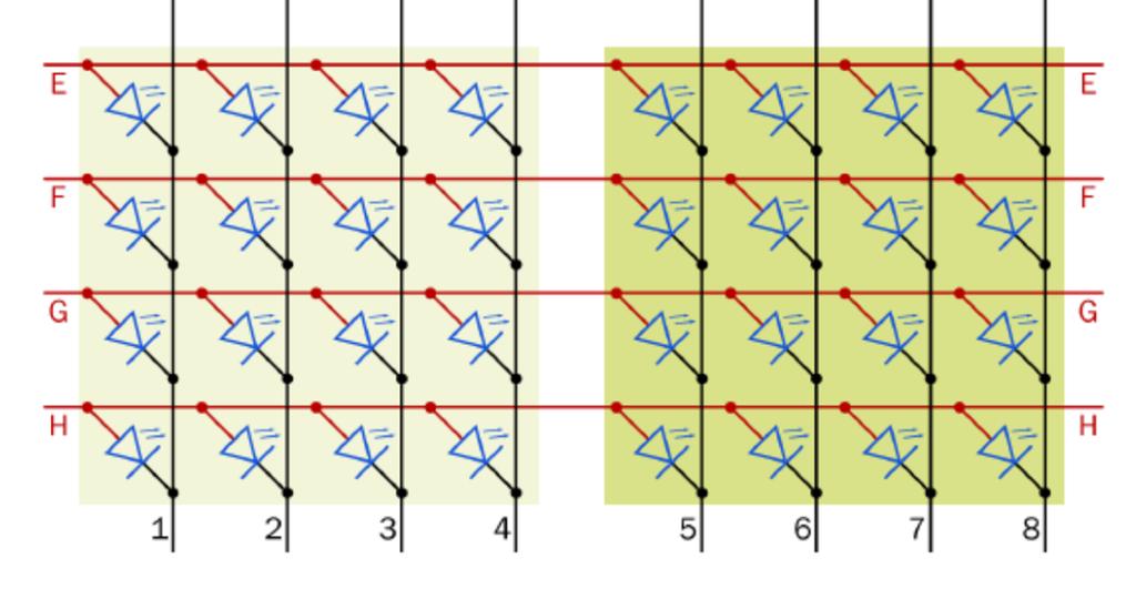
21 With A Little Wire Renumbering 21
22 GOOD DESIGN PRACTICES 22
23 Debugging Debugging complex systems is very hard It is too hard to figure out what should be happening This is why we try to create clean software interfaces Debugging hardware has similar issues Want to check well defined interfaces First check your tools/inputs Measure inputs (including Vdd) And check that the scope/meter are working Then check the smallest subcircuit you can Unfortunately hardware can break Could work yesterday and not work today Good to record what a working solutions looks like Check these voltages when it stops working 23
24 Debugging Hardware / Software Systems Often project has hardware and software What happens when this system breaks? Again isolation is the key In addition to having the main software Always have test software This should just double check that the hardware is working E.g. checking that all the LEDs light in the right order Test jigs are great Either software only (output on a screen/ computer) Or other hardware/software that is known to work Can test/debug your software/hardware 24
25 Debugging the Smart Useless Box Isolation is key: In prelab Tested power inverters in simulation Wrote test programs to read switches and drive the motor In lab Measure the output of the Arduino directly Test power inverters directly Use test programs to debug your wiring Use std simple debugging Use Serial.println(keyVariable) To help figure out where the code is going wrong Check for the std stupid C errors Like using = in an if statement 25
26 Archive Your Test Programs Remember that hardware sometimes stops working Either because you hit a bug you missed before Or a component that used to work isn t anymore Need to figure out which is which Having code that can measure/test hardware is crucial Then when system stops working can check hardware is ok Or narrow down to which component is no longer working 26
27 Minimizing Work Required When you start a project you have a choice What will you design What will you borrow from others Design only the critical stuff you need Borrow the rest from others Don t invent stuff you don t need Good enough is really good enough Think about the minimal system that is ok Think also about the things you might like to add later But build this minimal system first When it works, you can then start adding stuff 27
28 Hacking is Rarely the Best Approach If you are going to do this only once And will never use it again You can hack your way through it, just to get it done If you are going to do this more than once Creating an efficient method will save you time in the end Building jigs is often a time saver And you rarely do things only once Because you make mistakes Or performance / aesthetics of unit is important Remember if you are doing something for the 2 nd time There will probably be a 3 rd, so think about your methodology 28
29 Failing Fast People don t like to fail So they tend to avoid areas that they are worried about This is exactly backward to being successful You actually want to fail as fast as you can If something is not going to work Why waste time working on the other stuff? Don t you want to know ASAP so you can t stop working on it? Should always work on the most risky part of the project first Mantra in entrepreneurship Often knowing what the customer wants is the hardest point So try many products/variations until you find one that wins 29
30 Failing Fast It is easier to modify designs early in the process If something is not going to work Find out early when you can change other components/project Have less sunk investment to lose Failing is learning You fail because of an conceptual error The world is different than what you thought Learning the way the world really is, is important Debugging is easier in smaller chunks Want to test the smallest chunk possible If something is risky, would like to isolate it to debug it 30

31 31
32 By the End of Lecture, You Should Be Able To: Create the circuit to drive your LED cube from your Arduino Map the x, y coordinate of the folder LED array to Its x, y, z position in the cube Create a set of clean interfaces to test your design To separate the hardware test from the software test Work to fail fast in your projects Do risky stuff first, not last, to minimize cost of failure Faster learning cycles 32
Lecture 12. Building an LED Display
 Lecture 12 Building an LED Display Copyright 2017 by Mark Horowitz 1 By the End of Lecture, You Should Be Able To: Use LEDs in simple circuits Use time division multiplexing to control LEDs Control n 2
E40M. Binary Numbers, Codes. M. Horowitz, J. Plummer, R. Howe 1
 E40M Binary Numbers, Codes M. Horowitz, J. Plummer, R. Howe 1 Reading Chapter 5 in the reader A&L 5.6 M. Horowitz, J. Plummer, R. Howe 2 Useless Box Lab Project #2 Adding a computer to the Useless Box
E40M Useless Box, Boolean Logic. M. Horowitz, J. Plummer, R. Howe 1
 E40M Useless Box, Boolean Logic M. Horowitz, J. Plummer, R. Howe 1 Useless Box Lab Project #2 Motor Battery pack Two switches The one you switch A limit switch The first version of the box you will build
E40M Useless Box, Boolean Logic. M. Horowitz, J. Plummer, R. Howe 1
 E40M Useless Box, Boolean Logic M. Horowitz, J. Plummer, R. Howe 1 Useless Box Lab Project #2a Motor Battery pack Two switches The one you switch A limit switch The first version of the box you will build
E40M. Solving Circuits using Nodal Analysis and EveryCircuit TM. M. Horowitz, J. Plummer, R. Howe 1
 E40M Solving Circuits using Nodal Analysis and EveryCircuit TM M. Horowitz, J. Plummer, R. Howe 1 How Do We Figure Out the Voltages and Currents? Diode Solar Cell Li Bat Volt Conv R In this set of lecture
E40M. An Introduction to Making: What is EE?
 E40M An Introduction to Making: What is EE? Jim Plummer Stanford University plummer@stanford.edu Chuan-Zheng Lee Stanford University czlee@stanford.edu Roger Howe Stanford University rthowe@stanford.edu
How Do We Figure Out the Voltages and Currents?
 How Do We Figure Out the Voltages and Currents? Diode Solar Cell Li Bat Volt Conv R In this set of lecture notes we ll develop methods to analyze circuits. M. Horowitz, J. Plummer, R. Howe 2 Useless Box
E40M. Solving Circuits using Nodal Analysis, Part II and EveryCircuit TM. M. Horowitz, J. Plummer, R. Howe 1
 E40M Solving Circuits using Nodal Analysis, Part II and EveryCircuit TM M. Horowitz, J. Plummer, R. Howe 1 The Key Idea from Last Lecture Systematic Nodal Analysis 1. Label all the nodes (V A, V B, or
EE 330 Laboratory 3 Layout, DRC, and LVS Fall 2015
 EE 330 Laboratory 3 Layout, DRC, and LVS Fall 2015 Contents Objective:... 2 Part 1 Creating a layout... 2 1.1 Run DRC Early and Often... 2 1.2 Create N active and connect the transistors... 3 1.3 Vias...
Computer Science 324 Computer Architecture Mount Holyoke College Fall Topic Notes: Building Memory
 Computer Science 324 Computer rchitecture Mount Holyoke College Fall 2007 Topic Notes: Building Memory We ll next look at how we can use the devices we ve been looking at to construct memory. Tristate
E40M. MOS Transistors, CMOS Logic Circuits, and Cheap, Powerful Computers. M. Horowitz, J. Plummer, R. Howe 1
 E40M MOS Transistors, CMOS Logic Circuits, and Cheap, Powerful Computers M. Horowitz, J. Plummer, R. Howe 1 Reading Chapter 4 in the reader For more details look at A&L 5.1 Digital Signals (goes in much
E40M LEDs, Time Multiplexing. M. Horowitz, J. Plummer, R. Howe 1
 E40M LEDs, Time Multiplexing M. Horowitz, J. Plummer, R. Howe 1 Reading Course Reader 2.6 LEDs Course Reader 5.8 - Multiplexing LEDs https://learn.adafruit.com/all-about-leds http://dangerousprototypes.com/docs/
Topic Notes: Building Memory
 Computer Science 220 ssembly Language & Comp. rchitecture Siena College Fall 2011 Topic Notes: Building Memory We ll next see how we can use flip-flop devices to construct memory. Buffers We ve seen and
E40M LEDs, Time Multiplexing. M. Horowitz, J. Plummer, R. Howe 1
 E40M LEDs, Time Multiplexing M. Horowitz, J. Plummer, R. Howe 1 Reading Course Reader 2.6 LEDs Course Reader 5.8 - Multiplexing LEDs https://learn.adafruit.com/all-about-leds http://dangerousprototypes.com/docs/
EE 330 Laboratory 3 Layout, DRC, and LVS
 EE 330 Laboratory 3 Layout, DRC, and LVS Spring 2018 Contents Objective:... 2 Part 1 creating a layout... 2 1.1 Run DRC... 2 1.2 Stick Diagram to Physical Layer... 3 1.3 Bulk Connections... 3 1.4 Pins...
Digital Systems Design with PLDs and FPGAs Kuruvilla Varghese Department of Electronic Systems Engineering Indian Institute of Science Bangalore
 Digital Systems Design with PLDs and FPGAs Kuruvilla Varghese Department of Electronic Systems Engineering Indian Institute of Science Bangalore Lecture-31 Evolution of PLDs So welcome to this lecture
Module 3B: Arduino as Power Supply
 Name/NetID: Teammate/NetID: Module 3B: Laboratory Outline As you work on through the labs during the semester and some of the modules you may want to continue experimenting at home. Luckily the microprocessor
Welcome to Lab! You do not need to keep the same partner from last lab. We will come around checking your prelabs after we introduce the lab
 Welcome to Lab! Feel free to get started until we start talking! The lab document is located on the course website: http://users.wpi.edu/~ndemarinis/ece2049/ You do not need to keep the same partner from
1/Build a Mintronics: MintDuino
 1/Build a Mintronics: The is perfect for anyone interested in learning (or teaching) the fundamentals of how micro controllers work. It will have you building your own micro controller from scratch on
cs281: Introduction to Computer Systems Lab03 K-Map Simplification for an LED-based Circuit Decimal Input LED Result LED3 LED2 LED1 LED3 LED2 1, 2
 cs28: Introduction to Computer Systems Lab3 K-Map Simplification for an LED-based Circuit Overview In this lab, we will build a more complex combinational circuit than the mux or sum bit of a full adder
CSMIO IP. Differential outputs Addition. copyright 2012 CS-Lab s.c.
 CSMIO IP Differential outputs Addition copyright 2012 CS-Lab s.c. Index 1 General information Why differential outputs?... 3 1.1 Signs used in this guide... 3 2 Connection samples... 4 2.1 Motors drivers
Arduino 05: Digital I/O. Jeffrey A. Meunier University of Connecticut
 Arduino 05: Digital I/O Jeffrey A. Meunier jeffm@engr.uconn.edu University of Connecticut About: How to use this document I designed this tutorial to be tall and narrow so that you can read it on one side
ENGR 40M Project 4b: Displaying ECG waveforms. Lab is due Monday June 4, 11:59pm
 ENGR 40M Project 4b: Displaying ECG waveforms Lab is due Monday June 4, 11:59pm 1 Introduction Last week, you built a circuit that amplified a small 1Hz simulated heartbeat signal. In this week s you will
COMP combinational logic 1 Jan. 18, 2016
 In lectures 1 and 2, we looked at representations of numbers. For the case of integers, we saw that we could perform addition of two numbers using a binary representation and using the same algorithm that
Physics 120/220 Lab Equipment, Hints & Tips
 Physics 120/220 Lab Equipment, Hints & Tips Solderless Breadboard... 2 Power supply... 4 Multimeters... 5 Function generator... 5 Oscilloscope... 6 10X probe... 7 Resistor color code... 7 Components...
ENGR 40M Project 3c: Coding the raindrop pattern
 ENGR 40M Project 3c: Coding the raindrop pattern For due dates, see the overview handout The raindrop pattern works like this: Once per time period (say, 150 ms), (a) move the pattern one plane down: the
Discharge by touching: BNC coax shield, outlet metal cover plate, wire connected to GND
 Step-down transformer Very High Voltage Very Low Current Lower Voltage, 110V Power Station Grounding contact (3rd wire) Faulty wiring makes box hot!! Current path splits: 1) to ground (mostly) 2) through
Illuminating the Big Picture
 EE16A Imaging 2 Why? Imaging 1: Finding a link between physical quantities and voltage is powerful If you can digitize it, you can do anything (IOT devices, internet, code, processing) Imaging 2: What
Note. The above image and many others are courtesy of - this is a wonderful resource for designing circuits.
 Robotics and Electronics Unit 2. Arduino Objectives. Students will understand the basic characteristics of an Arduino Uno microcontroller. understand the basic structure of an Arduino program. know how
Halloween Pumpkinusing. Wednesday, October 17, 12
 Halloween Pumpkinusing Blink LED 1 What you will need: 1 MSP-EXP430G2 1 3 x 2 Breadboard 3 560 Ohm Resistors 3 LED s (in Red Color Range) 3 Male to female jumper wires 1 Double AA BatteryPack 2 AA Batteries
Coding Workshop. Learning to Program with an Arduino. Lecture Notes. Programming Introduction Values Assignment Arithmetic.
 Coding Workshop Learning to Program with an Arduino Lecture Notes Table of Contents Programming ntroduction Values Assignment Arithmetic Control Tests f Blocks For Blocks Functions Arduino Main Functions
Instructions for designing the HelloWorld circuit board using Autodesk Eagle 8.6.0
 Instructions for designing the HelloWorld circuit board using Autodesk Eagle 8.6.0 FABLAB BRIGHTON 2018 These instructions take you through step-by-step the process of creating the full circuit board design
12v Power Controller Project Board
 12v Power Controller Project Board 12 Volt Power Controller Introduction This board provides three functions... DC power gate Low voltage disconnect Voltage / current display The typical usage for this
Thursday, September 15, electronic components
 electronic components a desktop computer relatively complex inside: screen (CRT) disk drive backup battery power supply connectors for: keyboard printer n more! Thursday, September 15, 2011 integrated
Department of Computer Science. Software Usage Guide. CSC132 Programming Principles 2. By Andreas Grondoudis
 Department of Computer Science Software Usage Guide To provide a basic know-how regarding the software to be used for CSC132 Programming Principles 2 By Andreas Grondoudis WHAT SOFTWARE AM I GOING TO NEED/USE?...2
Welcome to Lab! Feel free to get started until we start talking! The lab document is located on the course website:
 Welcome to Lab! Feel free to get started until we start talking! The lab document is located on the course website: https://users.wpi.edu/~sjarvis/ece2049_smj/ We will come around checking your pre-labs
Embedded Systems and Software
 Embedded Systems and Software Lecture 12 Some Hardware Considerations Hardware Considerations Slide 1 Logic States Digital signals may be in one of three states State 1: High, or 1. Using positive logic
Lecture 4a. CMOS Fabrication, Layout and Simulation. R. Saleh Dept. of ECE University of British Columbia
 Lecture 4a CMOS Fabrication, Layout and Simulation R. Saleh Dept. of ECE University of British Columbia res@ece.ubc.ca 1 Fabrication Fabrication is the process used to create devices and wires. Transistors
Lab 2.2 Ohm s Law and Introduction to Arduinos
 Lab 2.2 Ohm s Law and Introduction to Arduinos Objectives: Get experience using an Arduino Learn to use a multimeter to measure Potential units of volts (V) Current units of amps (A) Resistance units of
3. The circuit is composed of 1 set of Relay circuit.
 Part Number : Product Name : FK-FA1420 ONE CHANNEL 12V RELAY MODULE This is the experimental module for a relay controller as the fundamental controlling programming. It is adaptable or is able to upgrade
Introduction to PSpice
 Introduction to PSpice Simulation Software 1 The Origins of SPICE In the 1960 s, simulation software begins CANCER Computer Analysis of Nonlinear Circuits, Excluding Radiation Developed at the University
Robotics and Electronics Unit 5
 Robotics and Electronics Unit 5 Objectives. Students will work with mechanical push buttons understand the shortcomings of the delay function and how to use the millis function. In this unit we will use
E85: Digital Design and Computer Engineering Lab 1: Electrical Characteristics of Logic Gates
 E85: Digital Design and Computer Engineering Lab 1: Electrical Characteristics of Logic Gates Objective The purpose of this lab is to become comfortable with logic gates as physical objects, to interpret
Lecture 11: MOS Memory
 Lecture 11: MOS Memory MAH, AEN EE271 Lecture 11 1 Memory Reading W&E 8.3.1-8.3.2 - Memory Design Introduction Memories are one of the most useful VLSI building blocks. One reason for their utility is
What s a Tri-state Buffer?
 What s a Tri-state Buffer? 2003 by Charles C. Lin. All rights reserved. Introduction Before we talk about tri-state buffers, let s talk about an inverter. You can read about inverters in the notes about
EK307 Lab: Microcontrollers
 EK307 Lab: Microcontrollers Laboratory Goal: Program a microcontroller to perform a variety of digital tasks. Learning Objectives: Learn how to program and use the Atmega 323 microcontroller Suggested
EECS 140 Laboratory Exercise 4 3-to-11 Counter Implementation
 EECS 140 Laboratory Exercise 4 3-to-11 Counter Implementation 1. Objectives A. To apply knowledge of combinatorial design. B. Gain expertise in designing and building a simple combinatorial circuit This
7 8 9 C. PRELAB REQUIREMENTS You must adhere to the Lab Rules and Policies document for every lab.
 Page 1/ Revision 1 OBJECTIVES To understand how a keypad functions as a raster scan input device and to learn how to interface a keypad to a microprocessor. Further explore and understand the implementation
Silicon Steroids for the Stamp Help Your Projects Heft Big Loads Using Switching Transistors
 Column #6, August 1995 by Scott Edwards: Silicon Steroids for the Stamp Help Your Projects Heft Big Loads Using Switching Transistors ONE of the outstanding characteristics of the PIC microcontroller used
Step 1: Downloading the source files
 Introduction: In this lab and in the remainder of the ELEC 2607 labs, you will be using the Xilinx ISE to enter and simulate the designs for your circuits. In labs 3 and 4, you will use ISE to compile
PARTS LIST 1 x PC Board 36 x 5mm Red LED 36 x 12mm LED Standoff 36 x NPN Transistor 36 x 10kΩ Resistor OTHER PARTS YOU MAY NEED
 PARTS LIST 1 x PC Board 36 x 5mm Red LED 36 x 12mm LED Standoff 36 x NPN Transistor 36 x 150Ω Resistor 36 x 10kΩ Resistor 17 x Mini Toggle on-off 8 x Mini Toggle (on)-off-(on) 1 x 470Ω Resistor 1 x 47µF
Additional Slides for Lecture 17. EE 271 Lecture 17
 Additional Slides for Lecture 17 Advantages/Disadvantages of Wire Bonding Pros Cost: cheapest packages use wire bonding Allows ready access to front side of die for probing Cons Relatively high inductance
Programming Principles 1 (CSC131) & 2 (CSC132) Software usage guide
 & 2 (CSC132) Software usage guide") School of Sciences Department of Computer Science and Engineering Programming Principles 1 (CSC131) & 2 (CSC132) Software usage guide WHAT SOFTWARE AM I GOING TO NEED/USE?... 3 WHERE DO I FIND THE SOFTWARE?...
School of Sciences Department of Computer Science and Engineering Programming Principles 1 (CSC131) & 2 (CSC132) Software usage guide WHAT SOFTWARE AM I GOING TO NEED/USE?... 3 WHERE DO I FIND THE SOFTWARE?...
Connecting LEDs to the ADB I/O
 Application Note AN-2 By Magnus Pettersson September 26 1996 Connecting LEDs to the I/O Introduction The following notes are for those of you who are a bit inexperienced with hardware components. This
How to approach a computational problem
 How to approach a computational problem A lot of people find computer programming difficult, especially when they first get started with it. Sometimes the problems are problems specifically related to
(Refer Slide Time 6:48)
") Digital Circuits and Systems Prof. S. Srinivasan Department of Electrical Engineering Indian Institute of Technology Madras Lecture - 8 Karnaugh Map Minimization using Maxterms We have been taking about
Digital Circuits and Systems Prof. S. Srinivasan Department of Electrical Engineering Indian Institute of Technology Madras Lecture - 8 Karnaugh Map Minimization using Maxterms We have been taking about
Building your own special-purpose embedded system gadget.
 Bare-duino Building your own special-purpose embedded system gadget. Saves a little money. You can configure the hardware exactly the way that you want. Plus, it s fun! bare-duino 1 Arduino Uno reset I/O
Chapter 19. Floppy Disk Controller Discussion. Floppy Disk Controller 127
 Floppy Disk Controller 127 Chapter 19 Floppy Disk Controller 19-1. Discussion Without some "mass storage" device such as a floppy disk, even the largest computer would still be just a toy. The SK68K can
Introduction to CMOS VLSI Design (E158) Lecture 7: Synthesis and Floorplanning
 Lecture 7: Synthesis and Floorplanning") Harris Introduction to CMOS VLSI Design (E158) Lecture 7: Synthesis and Floorplanning David Harris Harvey Mudd College David_Harris@hmc.edu Based on EE271 developed by Mark Horowitz, Stanford University
Harris Introduction to CMOS VLSI Design (E158) Lecture 7: Synthesis and Floorplanning David Harris Harvey Mudd College David_Harris@hmc.edu Based on EE271 developed by Mark Horowitz, Stanford University
Digital Circuits. Page 1 of 5. I. Before coming to lab. II. Learning Objectives. III. Materials
 I. Before coming to lab Read this handout and the supplemental. Also read the handout on Digital Electronics found on the course website. II. Learning Objectives Using transistors and resistors, you'll
Outline for Today. Lab Equipment & Procedures. Teaching Assistants. Announcements
 Announcements Homework #2 (due before class) submit file on LMS. Submit a soft copy using LMS, everybody individually. Log onto the course LMS site Online Assignments Homework 2 Upload your corrected HW2-vn.c
The name of our class will be Yo. Type that in where it says Class Name. Don t hit the OK button yet.
 Mr G s Java Jive #2: Yo! Our First Program With this handout you ll write your first program, which we ll call Yo. Programs, Classes, and Objects, Oh My! People regularly refer to Java as a language that
Boot Camp. Dave Eckhardt Bruce Maggs
 Boot Camp Dave Eckhardt de0u@andrew.cmu.edu Bruce Maggs bmm@cs.cmu.edu 1 This Is a Hard Class Traditional hazards 410 letter grade one lower than other classes All other classes this semester: one grade
Keypad Interfacing. Microcomputer Architecture and Interfacing Colorado School of Mines Professor William Hoff
 Keypad Interfacing Typical keypads have 12 or 16 buttons Keypad A mechanical keypad simply consists of a set of vertical wires (one for each column) and a set of horizontal wires (one for each row) When
AUDIO AMPLIFIER PROJECT
 Intro to Electronics 110 - Audio Amplifier Project AUDIO AMPLIFIER PROJECT In this project, you will learn how to master a device by studying all the parts and building it with a partner. Our test subject:
ENGR 40M Project 3c: Switch debouncing
 ENGR 40M Project 3c: Switch debouncing For due dates, see the overview handout 1 Introduction This week, you will build on the previous two labs and program the Arduino to respond to an input from the
Learning the Binary System
 Learning the Binary System www.brainlubeonline.com/counting_on_binary/ Formated to L A TEX: /25/22 Abstract This is a document on the base-2 abstract numerical system, or Binary system. This is a VERY
Using PSpice to Simulate Transmission Lines K. A. Connor Summer 2000 Fields and Waves I
 Using PSpice to Simulate Transmission Lines K. A. Connor Summer 2000 Fields and Waves I We want to produce the image shown above as a screen capture or below as the schematic of this circuit. R1 V1 25
Mark Schutzer December 9, 2007 (updated fix for older rev B and C ProCabs)
") Turning on radio ProCabs / PowerCabs Mark Schutzer December 9, 2007 (updated fix for older rev B and C ProCabs) Overview This paper will look into and explain why radio ProCabs / PowerCabs are hard to
Turning on radio ProCabs / PowerCabs Mark Schutzer December 9, 2007 (updated fix for older rev B and C ProCabs) Overview This paper will look into and explain why radio ProCabs / PowerCabs are hard to
TMC3in1 Torch & Motion Controller 3in1. Vol. 04: FAQ and Troubleshooting Guide
 TMC3in1 Torch & Motion Controller 3in1 Plasma THC - 5 Axis Breakout Board Spindle Controller Vol. 04: FAQ and Troubleshooting Guide For use with TMC3in1 Plugin Rev: 4.2.x.x Author: Randall L Ray Very Sr.
University of Florida EEL 3701 Dr. Eric M. Schwartz Department of Electrical & Computer Engineering Revision 0 12-Jun-16
 Page 1/14 Quartus Tutorial with Basic Graphical Gate Entry and Simulation Example Problem Given the logic equation Y = A*/B + /C, implement this equation using a two input AND gate, a two input OR gate
UNIVERSITY OF CALIFORNIA College of Engineering Department of Electrical Engineering and Computer Sciences Lab #2: Layout and Simulation
 UNIVERSITY OF CALIFORNIA College of Engineering Department of Electrical Engineering and Computer Sciences Lab #2: Layout and Simulation NTU IC541CA 1 Assumed Knowledge This lab assumes use of the Electric
Physics E-1bxl and PS3 Lab 4: Neuron Model 2016
 I. Before coming to lab Read this handout. Also review the background supplemental for Lab 3:Digital Circuits especially the sections on breadboard layout, transistors, and LEDs. Carefully study the circuit
COS 116 The Computational Universe Laboratory 7: Digital Logic I
 COS 116 The Computational Universe Laboratory 7: Digital Logic I In this lab you ll construct simple combinational circuits in software, using a simulator, and also in hardware, with a breadboard and silicon
UART Thou Mad? An Introduction to the UART Hardware Interface. Mickey Shkatov. Toby Kohlenberg
 UART Thou Mad? An Introduction to the UART Hardware Interface Mickey Shkatov Toby Kohlenberg 1 Table of Contents Abstract... 2 Introduction to UART... 2 Essential Tools... 4 UART and Security... 5 Conclusion...
If I wanted to connect an LED and little light bulb and have them switch on and off with one switch, my schematic would look like the one below.
 Relays Relays are great tools for turning on and off entire circuits, either with a small control switch, or with a microcontroller like the Arduino. To understand how relays are useful and how to control
Lecture 14: Prototyping and Schematics
 Lecture 14: Prototyping and Schematics Breadboards have some limitations They have high parasitic inductance and capacitance, limiting high frequency signal transfer to about 50MHz. Wire connections
EE 330 Spring 2018 Laboratory 2: Basic Boolean Circuits
 EE 330 Spring 2018 Laboratory 2: Basic Boolean Circuits Contents Objective:... 2 Part 1: Introduction... 2 Part 2 Simulation of a CMOS Inverter... 3 Part 2.1 Attaching technology information... 3 Part
Parallel I/O and Keyboard Scanning
 4 4.1 Objectives: Microprocessors can monitor the outside world using input ports. They can also control it using output ports. The TM4C123G (Tiva) performs I/O using 6 ports. Computer keyboards are typically
Select the technology library: NCSU_TechLib_ami06, then press OK.
 ECE 126 Inverter Tutorial: Schematic & Symbol Creation Created for GWU by Anis Nurashikin Nordin & Thomas Farmer Tutorial adapted from: http://www.ee.ttu.edu/ee/cadence/commondirectory/final%20tutorials/digitalcircuitsimulationusingvirtuoso.doc
Digital Systems Design with PLDs and FPGAs Kuruvilla Varghese Department of Electronic Systems Engineering Indian Institute of Science Bangalore
 Digital Systems Design with PLDs and FPGAs Kuruvilla Varghese Department of Electronic Systems Engineering Indian Institute of Science Bangalore Lecture-32 Simple PLDs So welcome to just lecture on programmable
EECS 140 Laboratory Exercise 5 Prime Number Recognition
 1. Objectives EECS 140 Laboratory Exercise 5 Prime Number Recognition A. Become familiar with a design process B. Practice designing, building, and testing a simple combinational circuit 2. Discussion
Reliable programming
 Reliable programming How to write programs that work Think about reliability during design and implementation Test systematically When things break, fix them correctly Make sure everything stays fixed
DIY Kit 113. DUAL STEPPER MOTOR CONTROLLER
 INTRODUCTION This kit enables users to control two unipolar stepper motors via a parallel/printer port of a PC. Four digital inputs are also included. These can be used for monitoring external switches
9.2 Types of Errors in Hypothesis testing
 9.2 Types of Errors in Hypothesis testing 1 Mistakes we could make As I mentioned, when we take a sample we won t be 100% sure of something because we do not take a census (we only look at information
FPGA Programming Technology
 FPGA Programming Technology Static RAM: This Xilinx SRAM configuration cell is constructed from two cross-coupled inverters and uses a standard CMOS process. The configuration cell drives the gates of
Lab. Course Goals. Topics. What is VLSI design? What is an integrated circuit? VLSI Design Cycle. VLSI Design Automation
 Course Goals Lab Understand key components in VLSI designs Become familiar with design tools (Cadence) Understand design flows Understand behavioral, structural, and physical specifications Be able to
Designing Information Devices and Systems II Spring 2018 J. Roychowdhury and M. Maharbiz Discussion 1A
 EEC 16B esigning Information evices and ystems II pring 2018 J. Roychowdhury and M. Maharbiz iscussion 1A 1 igit Bases (N) p is used to indicate that the number N is expressed in base p. For example, (N)
Grelllbbb s ESP Flashamater Adaptimizer Assembly & User Guide
 Grelllbbb s ESP Flashamater Adaptimizer Assembly & User Guide Overview The GEFA (we don t understand Grelllbb any better than you do, so we ll just abbreviate it GEFA) is a small programming tool that
EQ-ROBO Programming : Ladybird Robot
 EQ-ROBO Programming : Ladybird Robot Program begin Input port setting Output port setting a b Robot goes forward if there is no obstacle in front of robot. If the robot detect the obstacle in front side
Educational Smart Breadboard
 Educational Smart Breadboard Team 68 - Chinemelum Chibuko, Minseong Kim and Mostafa Elkabir ECE 445 Project Proposal - Spring 2018 TA: Kexin Hui 1. Introduction 1.1. Objective The first time any kid or
2015 edition FT TYPE: Utility madbeanpedals. Previous version of the Road Rage:
 Road Rage 2015 edition FT TYPE: Utility madbeanpedals Previous version of the Road Rage: http://www.madbeanpedals.com/projects/roadrage/docs/roadrage.zip 1.25 W x 0.825 H 2015 change-log: Removed 10R current
Physics 364, Fall 2012, Lab #9 (Introduction to microprocessor programming with the Arduino) Lab for Monday, November 5
 Lab for Monday, November 5") Physics 364, Fall 2012, Lab #9 (Introduction to microprocessor programming with the Arduino) Lab for Monday, November 5 Up until this point we have been working with discrete digital components. Every
Physics 364, Fall 2012, Lab #9 (Introduction to microprocessor programming with the Arduino) Lab for Monday, November 5 Up until this point we have been working with discrete digital components. Every
ECE/CS Computer Design Lab
 ECE/CS 3710 Computer Design Lab Ken Stevens Fall 2009 ECE/CS 3710 Computer Design Lab Tue & Thu 3:40pm 5:00pm Lectures in WEB 110, Labs in MEB 3133 (DSL) Instructor: Ken Stevens MEB 4506 Office Hours:
Administrivia. Next Monday is Thanksgiving holiday. Tuesday and Wednesday the lab will be open for make-up labs. Lecture as usual on Thursday.
 Administrivia Next Monday is Thanksgiving holiday. Tuesday and Wednesday the lab will be open for make-up labs. Lecture as usual on Thursday. Lab notebooks will be due the week after Thanksgiving, when
Fire TV Quick Start BJM **DISCLAIMER**
 Fire TV Quick Start BJM **DISCLAIMER** All content is delivered by the creators of the APPS and ADD- ONS. There is no condoning the content of the APPS and ADD- ONS. There is no assumption of liability
How to Become an IoT Developer (and Have Fun!) Justin Mclean Class Software.
 Justin Mclean Class Software.") How to Become an IoT Developer (and Have Fun!) Justin Mclean Class Software Email: justin@classsoftware.com Twitter: @justinmclean Who am I? Freelance Developer - programming for 25 years Incubator PMC
How to Become an IoT Developer (and Have Fun!) Justin Mclean Class Software Email: justin@classsoftware.com Twitter: @justinmclean Who am I? Freelance Developer - programming for 25 years Incubator PMC
7.6 DI Technical Data. 140 DI135 Chapter 3. General Information
 7.6 DI135 7.6.1 Technical Data Module ID General Information Model Number Short Description C-UL-US Listed DI135 7DI135.70 2003 digital input module, 4 inputs 24 VDC, sink, incremental encoder operation:
Luxman DML replacement manual by PE1MMK (construction)
") Luxman DML replacement manual by PE1MMK (construction) 1. Dismantling Take your amplifier to a appropriate place to work on it, use a small cloth or plastic cover to place your amp on, otherwise you might
Luxman DML replacement manual by PE1MMK (construction) 1. Dismantling Take your amplifier to a appropriate place to work on it, use a small cloth or plastic cover to place your amp on, otherwise you might
Lecture 8: Synthesis, Implementation Constraints and High-Level Planning
 Lecture 8: Synthesis, Implementation Constraints and High-Level Planning MAH, AEN EE271 Lecture 8 1 Overview Reading Synopsys Verilog Guide WE 6.3.5-6.3.6 (gate array, standard cells) Introduction We have