Models VSP12824V & VSP12860V
|
|
|
- Jonah Mason
- 6 years ago
- Views:
Transcription
1 Programmable Voltage Interface Unit Models VSP12824V & VSP12860V Installation & Programming Manual
2 PREFACE Important Installation Information It is the purchasers responsibility to determine the suitability of this equipment and its derivatives for any given application, Scope cannot give specific advice in this manual, as each use will require independent evaluation. Scope has, wherever possible, employed extra safeguards or designed optional equipment to further monitor the system s performance. Certain system installations, operational requirements or budgets may, however, limit the effectiveness of these safeguards. Again, the suitability of the system for any given application must therefore be decided by the installer and their customer, relative to the application and risk. License This equipment is cleared for use within the USA under a license assigned to the exclusive importer, PIPS Holdings Inc. License No Certain restrictions apply in respect of power output and antenna installations. Alternative frequencies are available by formal license application (Form 600) via the FCC. These will not be subject to the same restrictions as the standard assigned license. You should obtain the FCC Rules and Regulations, Title 47, Part 80 to End, including Parts 90 and 95, available from the US Gov. Printing Office, GPO Bookstore, FCC Office or Important Safety Information Scope products are designed to operate safely when installed and used according to general safety practices. The following requirements should be observed at all times. Do NOT subject this equipment to: Mechanical shock Excessive humidity or moisture Extremes of temperature Corrosive liquids This equipment is designed for indoor use, unless expressly stated otherwise, and must not be used in classified Hazardous Areas, including areas containing explosive or flammable vapors, unless express authorization has been given in writing by the manufacturer. If in doubt, consult your local product dealer for further information. Do not obstruct any slots or openings in the product. These are provided for ventilation to ensure reliable operation of the product and to protect it from overheating. Only use a damp cloth for cleaning (not liquid or aerosol based cleaners), and ensure that any power is removed from the unit prior to beginning the cleaning operation. Removal of covers from the equipment must only be undertaken by authorized service personnel, who must ensure that power is isolated prior to removal. Page 2
3 PREFACE Equipment Applications It is the user s responsibility to determine the suitability of the Scope products for any given application. Scope, including its subsidiaries and Distributors, cannot provide specific advice within this manual, as each application will require independent evaluation. Common sense dictates that certain applications may require back up systems to cover in the event of mains or equipment failure. All applications should be thoroughly assessed by the installer in conjunction with the customer so as to minimize risk. Scope has no control of the use and application of the frequencies issued by the FCC. Some equipment that is individually licensed may have a greater degree of protection than other equipment that is operated on a FCC License Assignment basis. The following information, however, may be of benefit. Equipment Testing. Range tests should be carried out at least once a week on portable radio equipment, more often when critical criteria apply. This should involve testing the unit past the limit of its required working range. Good working practice dictates that a suitable system installation log, covering both portable and fixed equipment must be generated, together with a record of the dates when the system has been manually checked and/or serviced, (with the aid of suitable test equipment etc.) enabling the system performance to be compared with the original installation data. The frequency of the tests required will vary between applications. If portable equipment has been dropped or is worn by a person involved in an accident, the unit should be tested again before re-use. It must be stressed that the physical range tests are essential and that any construction work or movement of plant or equipment could alter the signaling capability of the unit. Radio equipment, like any other requires servicing from time to time to ensure that it is operating to its optimum performance. It is therefore essential that equipment is inspected and tested by authorized service centers at least once a year. Literature Scope Marketing (Communications UK) Ltd, the manufacturer, in conjunction with it s distributors operates a policy of continual improvement, and therefore reserve the right to modify or change any specifications without prior notice. While every possible care has been taken in the preparation of this manual, Scope does not accept any liability for technical or typographical errors or omissions contained herein, nor for incidental or consequential damage arising from the use of this material. Installation Installation must only be undertaken by an Approved contractor, who shall ensure that all work is carried out in compliance with the appropriate State and Federal Regulations. For mains powered equipment, a readily accessible isolating fuse or socket must be located within 1 meter of the equipment. Liability Scope does not accept liability for any damage or injury, howsoever caused as the result of misuse of this equipment. It is the responsibility of the user to ensure that the equipment is operated in the manner for which it was intended and that it is the correct item of equipment for the required task. Page 3
4 PREFACE Warranty This product is warranted as free from defects of workmanship and materials for a period of one year from the original purchase date. During this time, if there is a defect or malfunction of this product, Scope will, with proof of purchase, repair or replace at its discretion any defective parts, free of charge. This does not include where the adjustments, parts and repair are necessary due to circumstances beyond the control of Scope, including but not limited to fire or other casualty, accident, neglect, abuse, abnormal use or battery leakage damage. There are no other expressed or implied warranties except as stated herein, and those excluded include those of merchantability and fitness for a particular purpose. In no event will Scope or any of its agents be liable for direct, indirect, special incidental or consequential damages resulting from any defect in the product, even if advised of the possibility of such damages. The warranties and remedies set forth above are exclusive and in lieu of all others, oral or written, expressed or implied. No Scope distributor, dealer, agent or employee is authorized to make any modification, extension or addition to this warranty. Some states do not allow limitations on how long an implied warranty may last and some states do not allow exclusions or limitation of incidental or consequential damages. Warning! No User Serviceable Parts Alteration or modification to any part of this equipment, without the prior written consent of the manufacturer, will invalidate all manufacturer approvals and warranties. No adjustments can be undertaken except by qualified and licensed persons as defined by the FCC Rules and Regulations. Operation of altered equipment can result in fines, imprisonment, and/or confiscation of such equipment. Scope Marketing (Communications UK) Ltd, 2000 All Rights Reserved Page 4
5 Description This product has been designed specifically to work with nurse call systems that require four separate messages for each event. It consists of up to 128 opto-isolated inputs that will accept voltages from +12 to +30 volts dc (VSP12824V) and 5 to 60 volts DC or AC (VSP12860V). In response to a change of state on any input, messages selected from a table are sent via the serial port to a Scope paging transmitter. Each column of 8 inputs has a single common connector in the center of the group of terminals. The pager messages are held in a non-volatile memory (EEPROM) which can be programmed by using the Microsoft Windows Visual Basic program, Voltage Interface Program (VIP). The Serially Programmable Voltage Board consist of a total of 128 contact inputs and is housed in a 13 H x 7.5 W x 2.5 D wall mounted housing. Cable access is via four inputs fitted with strain relief couplings. The unit requires 12 vdc, which is supplied by a 115-volt ac adapter. The Serially Programmable Voltage Board is designed for use with a four-state nurse call system. The four states expected at the inputs are as follows. Voltage Pulsing at 2Hz Voltage Pulsing at 1Hz No Voltage Present Steady State Voltage Present Priority is given to the four conditions in the order shown above, with the 2Hz signal being the highest priority. All pending priority 1 calls are sent before the next priority calls are serviced. Because the need to analyze the conditions present on the inputs, the time between a condition being present, and the message being sent is approximately 2 seconds, depending upon the priority of the call, and other pending higher priority calls. This means that a condition must be present for about two seconds to be accepted. Once accepted, a condition will be paged, even if the state changes before it is paged. In this way, during high activity periods where many inputs may be changing, messages will not be lost providing the input state remains present for two seconds. The scanning procedure does not cease when an input changes, i.e. the system does not stop to analyze a single input, but scans all inputs a number of times (approx. 20ms for one scan) in the two second scanning period. Any pending messages continue to be sent during the scanning period, in this way the system operates continuously under all circumstances. Installation 1. Remove the cover by loosing the four screws located at the top and bottom of the unit. 2. The interface unit is mounted to the wall by four (4) mounting screws fixed through the back plate. Hold the back plate up to the mounting surface and mark the location of the mounting holes. Set the interface unit aside. 3. Using a ¼ drill bit, drill the marked holes 1-1/4 deep. 4. Using the supplied mounting hardware and mount the back plate to the mounting surface. 5. Connect alarm input leads to the appropriate terminal. Each set of eight (8) inputs has a single common. DO NOT TIE COMMONS TOGETHER. Negative to common and positive to contact input. Page 5

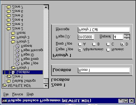
6 6. Install the AC adapter (115vac to 12vdc) to the interface unit and plug it into a 115 vac wall outlet. 7. Connect the interface unit to your computer serial port using the 10-foot 9-pin to 9-pin cable supplied with your unit. 8. Set the serial port on your computer for 9600 baud, parity of 8, N, Proceed to the programming section of this manual. 10. AFTER PROGRAMMING the interface unit, connect the unit to the ConneXions transmitter using the 10-foot 9-pin to 9-pin cable supplied with your unit. Programming Programming the contacts is accomplished by using the MS-Windows Voltage Interface Program. The MS-Windows Voltage Interface Program (VIP) is designed to run on any Microsoft platform. The license issued with the VIP program does not imply that you have a licensed to use any of the Microsoft products. If the user does not understand the operation of MS-Windows you should refer to the windows operations manual before installing the VIP software. The user can program one or all contacts. You can use a preprogrammed default file stored on a disk or read the configuration from the Voltage Interface unit and update the appropriate contact and reprogram the Interface unit. A. Definitions LOCATION The name of the location for this event. PRIORITY 1 Highest priority, Voltage input drops below 12VDC. Pulsing at 2Hz Rate. PRIORITY 2 Pulsing at a rate of 1Hz. PRIORITY 3 Standard Call, Voltage input drops to below 12VDC and stays off. RESET Voltage goes to 24 to 30 VDC steady. PAGER ID Enter the full Seven digits (i.e ) PAGER BEEP Alerts type A, B, C, or D. REPEAT The number you enter is how may times the system will Scan the 128 inputs before it will repeat the message of a triggered event. (i.e. if a number of 5 is in the REPEAT box, the system will scan the 128 contacts five time before transmitting a repeated message.) See chart on page 5 for REPEAT SETTING vs MINUTES. Page 6
 3. Enter changes. 4.")
7 B. Determine the type of programming to be preformed. 1. Modify the current configuration in the Voltage Interface Unit. 2. Program the Voltage Interface Unit with a new configuration. C. Modify current configuration 1. Select [Device], [Device Read]. 2. Select the Zone to be modified. (note: Zone = Contact) 3. Enter changes. 4. After all changes have been accomplished select [Device], [Device Write]. The system will load the edited file to the interface unit. Contact No. Highest Flash Rate Maximum 39 Characters Enter ALL Seven Digits of the Cap Code No. of Completed Scans before Repeat Figure 1 D. Program interface unit with new configuration 1. Use an existing file stored on disk. a. Select [FILE], [LOAD] b. Select the directory the file is located in and the file name. (see figure 2) c. Load File. (see figure 3) d. Select [DEVICE], [DEVICE WRITE] e. The program will transfer the file to the Voltage Interface Unit. Message Sent to Pager. Maximum 39 Characters No Repeat on Reset Repeat Setting vs Repeat Time 10 3 Minutes 15 5 Minutes 20 7 Minutes 25 8 Minutes Minutes Minutes Minutes Minutes Minutes Page 7

8 Figure 2 Figure 3 Page 8
![2. Develop new configuration using DEFAULT SETTINGS a. Select [DEFAULT SETTINGS], b. Enter only COMMON data.. (see figure 4) c. Select [ADD ANOTHER ZONE]. d. Enter the number of Zone(s) {contacts} you will be activating.](/docs-images/73/69273036/images/9-0.jpg "(see figure 5) NOTE: IF YOU ACTIVATE LESS THAN 128 CONTACTS, APPLY VOLTAGE ONLY TO THE ONES YOU ACTIVATED. THIS WAY THE OTHER CONTACTS WILL NOT ALARM. e.")
![The program will enter all default data into each zone. f. Edit each zone to add Pager ID if different, and any corrected messages. (see figure 6) The words [Room No] will appear for all events.](/docs-images/73/69273036/images/9-1.jpg "This Pager ID will appear for all Events. Edit if Necessary. This message will appear for all PRIORITY 1 events. Edit if necessary. Figure 4 Enter the number of Zones to be programmed. i.e. 1-50.")
9 2. Develop new configuration using DEFAULT SETTINGS a. Select [DEFAULT SETTINGS], b. Enter only COMMON data.. (see figure 4) c. Select [ADD ANOTHER ZONE]. d. Enter the number of Zone(s) {contacts} you will be activating. (see figure 5) NOTE: IF YOU ACTIVATE LESS THAN 128 CONTACTS, APPLY VOLTAGE ONLY TO THE ONES YOU ACTIVATED. THIS WAY THE OTHER CONTACTS WILL NOT ALARM. e. The program will enter all default data into each zone. f. Edit each zone to add Pager ID if different, and any corrected messages. (see figure 6) The words [Room No] will appear for all events. This Pager ID will appear for all Events. Edit if Necessary. This message will appear for all PRIORITY 1 events. Edit if necessary. Figure 4 Enter the number of Zones to be programmed. i.e A dash must separate the two numbers. Check this box to have room numbers automatically added to each zone. Figure 5 Page 9
![Figure 6 g. Select [DEVICE], [DEVICE WRITE]. New data will be transferred to the interface unit. h. Select [FILE], [SAVE AS] name file. This will save the file for future use.](/docs-images/73/69273036/images/10-0.jpg "Setting for Voltage Present Event Trigger Both VSP units can be configured to operate with a nurse call system using ZERO to POSITIVE pulsing.")
![However at the present time in this configuration you will not have a [REPEAT] function on the Room Call or Standard.](/docs-images/73/69273036/images/10-1.jpg "When voltage above a positive 12 volts is present would indicate a room call, PRIORITY 3, when the voltage dropped below 12 volts it would be in a reset condition.")
10 Figure 6 g. Select [DEVICE], [DEVICE WRITE]. New data will be transferred to the interface unit. h. Select [FILE], [SAVE AS] name file. This will save the file for future use. Setting for Voltage Present Event Trigger Both VSP units can be configured to operate with a nurse call system using ZERO to POSITIVE pulsing. However at the present time in this configuration you will not have a [REPEAT] function on the Room Call or Standard. When voltage above a positive 12 volts is present would indicate a room call, PRIORITY 3, when the voltage dropped below 12 volts it would be in a reset condition. With this configuration the location of the message text is different. See figure 6 and 7. This Priority is now the Reset Same as other. Configuration No Repeat Reset Message Figure 7 Page 10

11 This Reset is now a Priority 3 Call Priority 3 Room Call Message WITHOUT A REPEAT Figure 8 Calibration To allow for timing variations and tolerances between products, a calibration routine has been included. This should be carried out in conjunction with the host equipment at the time of installation. This operation requires that the VSP12860V or VSP12824V be connected to a terminal program. A. Setup 1. Connect unit to a desktop or laptop computer with a terminal program. 2. Set the communication port for 9600 baud, parity of N, 8, Place SW8 on the PCB to [ON]. 4. Connect a [PRIORITY 2 CALL] slower flashing condition to contact Apply power to the interface unit. 6. [ATTEMPTING TO CALIBRATE] will appear on the screen. 7. After the unit adjust the scan period, the message [CALIBRATION SUCCESSFUL TURN OFF SWITCH 8 AND HIT ANY KEY TO CONTINUE] will appear on the screen. 8. Place switch [8], [OFF]. 9. Hit any key. 10. Ensure the Priority 2 Call is still present on input Shortly thereafter this will produce a BATH CALL event to the screen. This indicates that the system has successfully adjusted itself to the timings present on the equipment to which it is connected. The calibration value is saved to non-volatile memory and will not be lost if power is removed form the system. This procedure should only need to be performed when the equipment is first installed, unless timing changes over time as components age. Page 11
12 THE SERIAL BAUD RATE OF THE VSP128 UNIT IS CHANGED BY THE DIP SWITCH, SW1 AS FOLLOWS: ALL DIP SWITCHES OFF BAUD DIP SWITCH 1 ON BAUD DIP SWITCH 2 ON BAUD DIP SWITCHES ON BAUD DIP SWITCH 3 ON BAUD DIP SWITCHES ON BAUD WHEN PROGRAMMING SET THE BAUD RATE TO 9600 BAUD. DURING PROGRAMMING THE VSP128 IS POWERED USING THE SUPPLIED PTPS12 POWER SUPPLY. THE SCAN LED WILL REMAIN ON DURING THE WRITE OPERATION. Page 12
VDI Pro Voltage & Dry Contact Interface Installation and programming Guide MODEL VDI MK2
 VDI Pro Voltage & Dry Contact Interface Installation and programming Guide MODEL VDI MK2 1 of 18 PREFACE Important Installation Information It is the purchasers responsibility to determine the suitability
MPA3 Mobile Personal Alarm MK3
 MPA3 Mobile Personal Alarm MK3 User Manual Scope Communications UK Ltd, Quantum House, Totnes, Devon TQ9 5AL United Kingdom Tel: +44(0)1803 860700 Fax: +44(0)1803 863716 www.scope-uk.com MPA3 Page 1 of
SATA II HDD Canister KISS DA 435 Quick Reference Guide
 SATA II HDD Canister KISS DA 435 Quick Reference Guide If it s embedded, it s Kontron 1. Table of Contents SATA II HDD Canister KISS DA 435 1. Table of Contents 1. Table of Contents... 1 2. Important Information...
CrystalView DVI Multi INSTALLATION AND OPERATIONS MANUAL Stancliff Road Phone: (281)
") CrystalView DVI Multi INSTALLATION AND OPERATIONS MANUAL 10707 Stancliff Road Phone: (281) 933-7673 Houston, Texas 77099 WWW.ROSE.COM LIMITED WARRANTY Rose Electronics warrants the CrystalView Multi to
CrystalView DVI Multi INSTALLATION AND OPERATIONS MANUAL 10707 Stancliff Road Phone: (281) 933-7673 Houston, Texas 77099 WWW.ROSE.COM LIMITED WARRANTY Rose Electronics warrants the CrystalView Multi to
Owner's Manual. For latest instructions please go to
 mycharge name and logo are registered trademarks of RFA Brands. 2012-2013 RFA Brands. All Rights Reserved. Patent Pending. Made in China. IB-MYC05001RM Owner's Manual For latest instructions please go
Debitek Card Revalue Station Installation Manual
 Page 1 of 5 Debitek Card Revalue Station Installation Manual General Description The Debitek Card Revalue Station family includes the Cash to Card, Cash to Card with Dispenser, Automatic Debit Machine,
2-Way Wireless I/O Expander Installation Guide
 2-Way Wireless I/O Expander Installation Guide For more detailed information please refer to the iconnect Installer Manual provided on our website: www.electronics-line.com Table of Contents 1. Introduction...
Chore-Tronics Mobile Server
 Chore-Tronics Mobile Server Installation & Operator s Instruction Manual Contact your nearby Chore-Time distributor or representative for additional parts and information. Chore-Time Group A division of
IOX-4. Installation Instructions. AXS-100 I/O Expander 1. INTRODUCTION 2. SPECIFICATIONS 3. MOUNTING DE6314 1
 AXS-100 I/O Expander 1. INTRODUCTION The is an input / output expander for the AXS-100 access control panel. It contains eight analog inputs and eight dry contact relays output. Up to four boards may be
CMSA-100 Manual. Cinema Media Server Automation
 CMSA-100 Manual Cinema Media Server Automation 181 Bonetti Drive San Luis Obispo, CA 93401-7397 USA Phone: +1 805 549 0161 Fax: +1 805 549 0163 www.uslinc.com Table of Contents 1. Safety Notice... 3 2.
3-4 SAS/SATA II HDD Canister Entry version USER S MANUAL XC-34D1-SA10-0-R. Document number: MAN A
 3-4 SAS/SATA II HDD Canister Entry version XC-34D1-SA10-0-R USER S MANUAL Document number: MAN-00077-A ii Preface Important Information Warranty Our product is warranted against defects in materials and
HDEXT50M USER MANUAL Extend HD Signals over CAT 5/5e/6 up to 164ft.(50m) All Rights Reserved Version: HDEXT50M_2017V1.2
 All Rights Reserved Version: HDEXT50M_2017V1.2") USER MANUAL Extend HD Signals over CAT 5/5e/6 up to 164ft.(50m) All Rights Reserved Version: _2017V1.2 Preface Read this user manual carefully before using this product. Pictures displayed in this manual
USER MANUAL Extend HD Signals over CAT 5/5e/6 up to 164ft.(50m) All Rights Reserved Version: _2017V1.2 Preface Read this user manual carefully before using this product. Pictures displayed in this manual
DisplayPort to DVI Converter
 DisplayPort to DVI Converter Model #: C-DP-DVI 2010 Avenview Inc. All rights reserved. The contents of this document are provided in connection with Avenview Inc. ( Avenview ) products. Avenview makes
Chapter 1 : FCC Radiation Norm...3. Chapter 2 : Package Contents...4. Chapter 3 : System Requirements...5. Chapter 4 : Hardware Description...
 Table of Contents Chapter 1 : FCC Radiation Norm...3 Chapter 2 : Package Contents...4 Chapter 3 : System Requirements...5 Chapter 4 : Hardware Description...6 Chapter 5 : Charging Your Keychain...7 Chapter
700 Series 200 Amp Clamp Meters
 700 Series 200 Amp Clamp Meters #61-700 #61-701 #61-702 1 2 3 6 5 7 4 8 1. Non-contact voltage (NCV) (#61-701 and #61-702) With the NCV tab on the tip of the clamp close to an AC voltage, press the NCV
SP-1009D. 1x9 Dual Link DVI Distribution Amplifier. User Manual. Made in Taiwan
 SP-1009D 1x9 Dual Link DVI Distribution Amplifier User Manual Made in Taiwan Safety and Notice The SP-1009D 1x9 Dual Link DVI Distribution Amplifier has been tested for conformance to safety regulations
Mini-DVI-WP Series WALL PLATE MINIATURE MULTIMODE FIBER OPTIC DVI TRANSMISSION SYSTEM
 Mini-DVI-WP Series WALL PLATE MINIATURE MULTIMODE FIBER OPTIC DVI TRANSMISSION SYSTEM BCI reserves the right to make changes to the products described herein without prior notice or consent. No liability
Bluetooth Enabled Access Control MODEL BG-FE. Operating Instructions
 BlueGuard FE Bluetooth Enabled Access Control MODEL BG-FE Operating Instructions CAUTION AND SAFETY INFORMATION IMPORTANT: If the equipment is used in a manner not specified in this manual, the protection
NIMBUS a personal dashboard for your digital life
 INVENTED BY REAL PEOPLE LIKE YOU Ryan Pendleton NIMBUS a personal dashboard for your digital life OVERVIEW Part of the Quirky + GE collection of smart products, Nimbus is a highly customizable 4-dial clock
LED FOLDING WORKLIGHT TM
 LED FOLDING WORKLIGHT TM LED LIGHT POWERSTRIP USB CHARGING ITM. / ART. 689211 Model: LM55812 CARE & USE INSTRUCTIONS IMPORTANT, RETAIN FOR FUTURE REFERENCE: READ CAREFULLY For assistance with assembly
Dual Component Video Wall Plate 6-RCA AT80COMP6
 Dual Component Video Wall Plate 6-RCA AT80COMP6 User Manual www.atlona.com TABLE OF CONTENTS 1. Introduction 2 2. Applications 2 3. Specifications 2 4. Installation 2 5. Safety Information 3 6. Warranty
User Manual AIMB-C200. Economical Embedded Chassis for Mini-ITX Motherboard
 User Manual AIMB-C200 Economical Embedded Chassis for Mini-ITX Motherboard Copyright The documentation and the software included with this product are copyrighted 2010 by Advantech Co., Ltd. All rights
DCS-E 1kW Series, DLM-E 3kW & 4kW Power Supplies
 DCS-E 1kW Series, DLM-E 3kW & 4kW Power Supplies M51A Option: Isolated Analog Programming Manual Power Supplies Elgar Electronics Corporation 9250 Brown Deer Road San Diego, CA 92121-2294 1-800-73ELGAR
1X2 HDMI Splitter with 3D Support
 AV Connectivity, Distribution And Beyond... VIDEO WALLS VIDEO PROCESSORS VIDEO MATRIX SWITCHES EXTENDERS SPLITTERS WIRELESS CABLES & ACCESSORIES 1X2 HDMI Splitter with 3D Support Model #: SPLIT-HDM3D-2
DVI EDID Reader / Writer
 DVI EDID Reader / Writer Model #: C-EDID-RW 2010 Avenview Inc. All rights reserved. The contents of this document are provided in connection with Avenview Inc. ( Avenview ) products. Avenview makes no
OPERATING INSTRUCTIONS POWERSMART 10 10,000 MAH PORTABLE POWER PLEASE READ BEFORE OPERATING THIS EQUIPMENT
 POWERSMART 10 10,000 MAH PORTABLE POWER OPERATING INSTRUCTIONS PLEASE READ BEFORE OPERATING THIS EQUIPMENT HALO POWERSMART 10 Thank you for choosing HALO. Innovative and easy to use, the HALO POWERSMART
Digital Contact Tachometer
 Digital Contact Tachometer Item 66400 Read this material before using this product. Failure to do so can result in serious injury. SAVE THIS MANUAL. When unpacking, make sure that the product is intact
User Guide. Control Box. RoscoLED TM.
 RoscoLED TM Control Box User Guide This guide applies to the following RoscoLED Control Box models: RoscoLED Control Box 300W/Static White (293 22250 0000) RoscoLED Control Box 400W/VariWhite (293 22260
PS8 - II. Professional Power Sequencer. User s Manual
 PS8 - II Professional Power Sequencer User s Manual IMPORTANT SAFETY INSTRUCTIONS READ FIRST This symbol, whenever it appears, alerts you to the presence of uninsulated dangerous voltage inside the enclosure.
ServerCall Transmitter
 ServerCall Transmitter SERVICE MANUAL www.alsindan.com info@alsindan.com Sindan Electrical Trading T: +971 6 5728 767 F: +971 6 5728 764 Made in Korea SERVERCALL TRANSMITTER MANUAL 1. Equipment Setup WALL
Broadband Automatic Disconnect Switch. User Manual
 Reset/Test Primary/ Primary Broadband Automatic Disconnect Switch User Manual Local Power Remote Pwer Local 63V Fault Secondary Select Secondary 220V Normal 990-1929 09/2004 Introduction Introduction
SpeedVault Model SV 500 User Manual
 SpeedVault Model SV 500 User Manual Patented Rev 1 (10/11) Firearm Safety WARNING: The SpeedVault safe or any other firearm storage device cannot take the place of other safety procedures including advising
XBDM. 1015LV, 1020LV, 1030LV, 1020HV Models USER & INSTALLATION MANUAL BYPASS DISTRIBUTION MODULE
 XBDM 1015LV, 1020LV, 1030LV, 1020HV Models USER & INSTALLATION MANUAL www.xpcc.com 2013 Xtreme Power Conversion Corporation. All rights reserved. Table of Contents IMPORTANT SAFETY INSTRUCTIONS:... 4 INTRODUCTION...
Owner s Instruction Manual
 Owner s Instruction Manual Advanced Healthcare Telephone Model 5150 Contents IMPORTANT SAFETY INSTRUCTIONS...3 BOX CONTENTS...4 FEATURES...4 ON/OFF SWITCH...4 DIAL BUTTONS...4 RECEIVER VOLUME CONTROL...4
CA-A480-A Elevator Controller. Reference & Installation Manual
 CA-A480-A Elevator Controller Reference & Installation Manual TABLE OF CONTENTS INTRODUCTION.................................................................. 4 Introduction.............................................................................................
LBO-H2 Series DIRECT PLUGGABLE LINKBRIDE TM FIBER OPTIC HDMI 2.0 TRANSMISSION SYSTEM
 LBO-H2 Series DIRECT PLUGGABLE LINKBRIDE TM FIBER OPTIC HDMI 2.0 TRANSMISSION SYSTEM BCI reserves the right to make changes to the products described herein without prior notice or consent. No liability
TVAC25100 TVAC25110 User manual
 TVAC25100 TVAC25110 User manual Version 11/2010 Original user manual. Keep for future use. 12 Introduction Dear Customer, Thank you for purchasing this product. This product meets the requirements of the
Lotus DX. sit-stand workstation. assembly and operation instructions. MODEL # s: LOTUS-DX-BLK LOTUS-DX-WHT
 Lotus DX assembly and operation instructions sit-stand workstation MODEL # s: LOTUS-DX-BLK LOTUS-DX-WHT safety warnings 13.6 Kg 30 lbs. 2.2 Kg 5 lbs. safety instructions/warning Read and follow all instructions
DVI Extender over Single CAT5 Mini SET
 DVI Extender over Single CAT5 Mini SET Model #: DVI-C5-M-SET 2010 Avenview Inc. All rights reserved. The contents of this document are provided in connection with Avenview Inc. ( Avenview ) products. Avenview
SPOTTER the multipurpose sensor
 SPOTTER the multipurpose sensor OVERVIEW Part of the Quirky + GE collection of smart products, Spotter is a multipurpose sensor that keeps you updated on what s going on at home from anywhere. Monitor
Y K Modem Module
 Y-308 56K Modem Module For use with Y-200 Series Electronic Boiler Sequencer & Outdoor Reset Control System Installation and Operating Manual CATALOG NO. 5000.65A Effective: 09-19-08 Replaces: 08-26-05
Kramer Electronics, Ltd. USER MANUAL. Model: VM-50AN. 1:5 Audio Distributor
 Kramer Electronics, Ltd. USER MANUAL Model: VM-50AN 1:5 Audio Distributor Contents Contents 1 Introduction 1 2 Getting Started 1 2.1 Quick Start 1 3 Overview 3 4 Your Audio VM-50AN 1:5 Distributor 4 5
Logitech Alert 700i/750i System Requirements & Support Guide
 Logitech Alert 700i/750i System Requirements & Support Guide Contents System Requirements............................ 3 Product Information............................ 4 Contact Us..................................
Innovative Circuit Technology Ltd.
 Innovative Circuit Technology Ltd. Pro Series DC Power Supply INSTRUCTION MANUAL 855-343-001 Models: ICT690-12S/ICT690-12SB ICT690-24S/ICT690-24SB ICT690-48S/ICT690-48SB ICT1190-12S/ICT1190-12SB ICT1190-24S/ICT1190-24SB
User's Guide. Extech AM A AC Analog Clamp Meter
 User's Guide Extech AM300 300A AC Analog Clamp Meter Introduction Congratulations on your purchase of the Extech AM300 Analog Clamp Meter. This device measure AC Voltage and Current, DC Voltage, and Resistance.
DCM Digital Control Modules
 DCM Digital Control Modules TECHNICAL MANUAL Version 1.2 November 2011 Safety Precautions Caution Read Instructions: Read and understand all safety and operating instructions before using the equipment.
FNet Repeater Installation & Operator s Instruction Manual
 FNet Repeater Installation & Operator s Instruction Manual October 2004 CTB Inc. Warranty FNet Repeater CTB Inc. Warranty CTB Inc. warrants each new Chore-Tronics product manufactured by it to be free
LINE VOLTAGE TESTER CT101 USER S MANUAL. Please read this manual carefully and thoroughly before using this product.
 LINE VOLTAGE TESTER USER S MANUAL CT101 Please read this manual carefully and thoroughly before using this product. KEY FEATURES Visual indication of AC or DC voltage Easy to use approved Safe for CAT
Pure Sinewave Inverter
 SINEWAVE INVERTER Pure Sinewave Inverter Model No. PST-25S-12E PST-25S-24E Manual Please read this manual before operating your inverter Notice of Copyright PST-255 inverter owner s manual 2004-2015 Samlex
SAFETY AND NOTICE TABLE OF CONTENTS INTRODUCTION FEATURES PACKAGE CONTENTS SUPPORTED RESOLUTIONS DIP SWITCH SPECIFICATIONS PANEL DESCRIPTIONS
 SAFETY AND NOTICE The VAC-12HS HDMI to 3G/HD/SD-SDI Converter has been tested for conformance to safety regulations and requirements, and has been certifi ed for international use. However, like all electronic
User's Guide. Model High Precision Quad Output DC Power Supply
 User's Guide Model 382270 High Precision Quad Output DC Power Supply Introduction Congratulations on your purchase of the Extech 382270 DC Power Supply. The Model 382270 can be used for many applications
Badger Meter Europa GmbH. INSTRUCTION MANUAL Deluxe LCD display for the MN series. September Version MN-Deluxe LCD display-09/01-e
 Badger Meter Europa GmbH INSTRUCTION MANUAL Deluxe LCD display for the MN series September 2001 Version MN-Deluxe LCD display-09/01-e Content Content Page 1. To the owner 1 2. Important information 1 3.
Digital Timer Outlet Model No.: EDT-1USA. Questions or Concerns? (855)
") Digital Timer Outlet Model No.: EDT-1USA Questions or Concerns? (855) 686-3835 support@etekcity.com Thank You. Thank you for purchasing the EDT-1USA Digital Timer Outlet by Etekcity. We are dedicated to
Digital Timer Outlet Model No.: EDT-1USA Questions or Concerns? (855) 686-3835 support@etekcity.com Thank You. Thank you for purchasing the EDT-1USA Digital Timer Outlet by Etekcity. We are dedicated to
READ FIRST! Notebook AC/DC Power Adapter Portable 120-Watt AC/DC Power Supply User Manual _Notebook_ACDC 11/23/04 1:37 PM Page 1
 33197_Notebook_ACDC 11/23/04 1:37 PM Page 1 READ FIRST! Notebook AC/DC Power Adapter Portable 120-Watt AC/DC Power Supply User Manual Notebook AC/DC Power Adapter 1 33197_Notebook_ACDC 11/23/04 1:37 PM
2 CHANNEL, CLASS D AMPLIFIERS PA2X25 PA2X60 PA2X125 PA2X150. pulseaudio1.com vanco1.com
 2 CHANNEL, CLASS D AMPLIFIERS PA2X25 PA2X60 PA2X125 PA2X150 pulseaudio1.com vanco1.com 800.626.6445 DEAR CUSTOMER Thank you for purchasing this product. For optimum performance and safety, please read
2 Port DVI Splitter. Model #: SPLIT-DVI
 2 Port DVI Splitter Model #: SPLIT-DVI-2 2010 Avenview Inc. All rights reserved. The contents of this document are provided in connection with Avenview Inc. ( Avenview ) products. Avenview makes no representations
Atlona 7 PRO HD Monitor with HDMI, VGA and Component Inputs
 AT-DIS7-PROHD User Manual Table of Contents 1. Introduction... 3 2. Applications... 3 3. Package Contents... 3 4. Features... 4 5. Specification... 4 6. Operation Controls and Functions a. Front Panel...
Kramer Electronics, Ltd. USER MANUAL. Model: VP-200XLN. XGA Line Amplifier / DA
 Kramer Electronics, Ltd. USER MANUAL Model: VP-200XLN XGA Line Amplifier / DA Contents Contents 1 Introduction 1 2 Getting Started 1 2.1 Quick Start 1 3 Overview 3 4 Your VP-200XLN XGA Line Amplifier /
PDS8u POWER DISTRIBUTION SYSTEM USER'S MANUAL
 PDS8u POWER DISTRIBUTION SYSTEM USER'S MANUAL 1 IMPORTANT SAFETY INSTRUCTION READ FIRST This symbol, whenever it appears, alerts you to the presence of uninsulated dangerous voltage inside the enclosure-voltage
DC-V3213XJ-4.3mm DC-V3213XJ-2.5mm
 Network Camera Quick Guide DC-V3213XJ-4.3mm DC-V3213XJ-2.5mm Powered by Safety Precautions WARNING RISK OF ELECTRIC SHOCK DO NOT OPEN WARNING: TO REDUCE THE RISK OF ELECTRIC SHOCK, DO NOT REMOVE COVER
User Manual TL-FO-HD. 4K Optical Fiber Extender. All Rights Reserved. Version: TL-FO-HD_160628
 User Manual TL-FO-HD 4K Optical Fiber Extender All Rights Reserved Version: TL-FO-HD_160628 Preface Read this user manual carefully before using this product. Pictures shown in this manual is for reference
User s Guide. 600A AC Clamp Meter. Model 38387
 User s Guide 600A AC Clamp Meter Model 38387 Safety International Safety Symbols This symbol, adjacent to another symbol or terminal, indicates the user must refer to the manual for further information.
Kramer Electronics, Ltd. USER MANUAL
 Kramer Electronics, Ltd. USER MANUAL Models: VP-200NK, 1:2 High Resolution XGA DA VP-300NK, 1:3 High Resolution XGA DA VP-400NK, 1:4 High Resolution XGA DA Contents Contents 1 Introduction 1 2 Getting
Atlona 1 by 4 HDMI Distribution Amplifier
 Atlona 1 by 4 HDMI Distribution Amplifier AT-HD-V14 User Manual TABLE OF CONTENTS 1. Introduction... 1 2. Features... 1 3. Package Contents... 2 4. Specifiations... 2 5. Panel Descriptions... 3 6. Hardware
Network Camera. Quick Guide DC-B1203X. Powered by
 Network Camera Quick Guide DC-B1203X Powered by Safety Precautions English WARNING RISK OF ELECTRIC SHOCK DO NOT OPEN WARNING: TO REDUCE THE RISK OF ELECTRIC SHOCK, DO NOT REMOVE COVER (OR BACK). NO USER-SERVICEABLE
PC-HELPER. Expansion Adapter for Express Card Slot EAD-CE-EC. User s Manual CONTEC CO.,LTD.
 PC-HELPER Expansion Adapter for Express Card Slot EAD-CE-EC User s Manual CONTEC CO.,LTD. Check Your Package Thank you for purchasing the CONTEC product. The product consists of the items listed below.
PWRguard PLUS Spring City Drive Waukesha, WI
 PWRguard PLUS www.westmountainradio.com 1020 Spring City Drive Waukesha, WI 53186 262-522-6503 sales@westmountainradio.com 2016, All rights reserved. All trademarks are the property of their respective
5 B&W Rear View System Camera
 5 B&W Rear View System Camera Instruction Manual MODEL: CA453 www.lorexcctv.com Copyright 2007 LOREX Technology Inc. Thank you for purchasing the Lorex 5 Black & White Rear View System Camera. This system
INSTRUCTION MANUAL DISTRIBUTION UNIT. Please read this manual thoroughly before use, and keep it handy for future reference.
 INSTRUCTION MANUAL DISTRIBUTION UNIT Please read this manual thoroughly before use, and keep it handy for future reference. ISSUE 1 May 2006 LIMITATION OF LIABILITY THE INFORMATION IN THIS PUBLICATION
W IRELESS8000 T. Powerful Universal Portable Charger PLEASE READ BEFORE OPERATING THIS EQUIPMENT
 W IRELESS8000 T M Powerful Universal Portable Charger PLEASE READ BEFORE OPERATING THIS EQUIPMENT HALO WIRELESS 8000 Thank you for choosing HALO. The HALO WIRELESS 8000 is a portable charger with 8000mAh
1x4 Splitter HDMI Distribution Amplifier with 4K2K & HDCP Support
 1x4 Splitter HDMI Distribution Amplifier with 4K2K & HDCP Support User s Guide Models PT-SP-HD14-4K Designed in Germany Made in Taiwan 2010 PureLink GmbH All rights reserved. www.purelink.de 1 Table of
4 Port USB Power Hub. Model: JH-800 USER MANUAL
 by 4 Port USB Power Hub Model: JH-800 USER MANUAL BEFORE INSTALLING AND USING THE PRODUCT, PLEASE READ THE INSTRUCTIONS THOROUGHLY, AND RETAIN THEM FOR FUTURE REFERENCE. Charging Port PRODUCT OVERVIEW
Bluetooth USB Adapter TALUS. User Guide
 Bluetooth USB Adapter TALUS User Guide Revision 0.1 1 User Guide for the TALUS Revision 1.0.1 Firmware version 1.0.X Printed in Korea Copyright Copyright 2008, SystemBase Co., Ltd. All rights reserved.
CV-505ZA. HDMI 2.0a Audio Extractor & Embedder. User Manual. rev: Made in Taiwan
 CV-505ZA HDMI 2.0a Audio Extractor & Embedder User Manual rev: 160825 Made in Taiwan Safety and Notice The CV-505ZA HDMI 2.0a Audio Extractor & Embedder has been tested for conformance to safety regulations
P O W E R S U P P L Y M A N U A L
 POWER SUPPLY MANUAL Congratulations on the purchase of your new Corsair power supply. This User Agreement (the Agreement ) is a legal agreement between you ( You ), and Corsair Memory, Inc. ( Corsair ).
Quick Start Guide. Dual USB Wall Charger with PD Charging, (x1) USB-A Port and (x1) USB-C Port. Model: U280-W02-A1C1
 USB-A Port and (x1) USB-C Port. Model: U280-W02-A1C1") Quick Start Guide Dual USB Wall Charger with PD Charging, (x1) USB-A Port and (x1) USB-C Port Model: U280-W02-A1C1 Este manual esta disponible en español en la página de Tripp Lite: www.tripplite.com Ce
Quick Start Guide Dual USB Wall Charger with PD Charging, (x1) USB-A Port and (x1) USB-C Port Model: U280-W02-A1C1 Este manual esta disponible en español en la página de Tripp Lite: www.tripplite.com Ce
TDM-170 TIMER DISPLAY
 TDM-170 TIMER DISPLAY TECHNICAL MANUAL Version 1.1 August 2016 TDM-170 Timer Display Technical Manual Safety Precautions Caution Read Instructions: Read and understand all safety and operating instructions
iq 16 Sync Charge Box
 USER INSTRUCTIONS iq 16 Sync Charge Box (iq 16 SCB Sync Station ) www.lockncharge.com iq 16 Sync Charge Box Contents Overview...1 Specifications...1 Safety instructions...2 Set up...2 How to charge multiple
DISCONTINUED PRODUCT DISCONTINUED PRODUCT
 Important Safety Instructions This manual contains important safety instructions that should be followed during the installation and maintenance of this product. Please read this manual thoroughly before
Grundfos MAGNA, GENI Module
 GRUNDFOS INSTRUCTIONS Grundfos MAGNA, GENI Module Installation and operating instructions 2 Grundfos MAGNA, GENI Module Installation and operating instructions 4 3 LIMITED WARRANTY Products manufactured
User s Guide. 600A True RMS AC/DC Clamp Meter. Model 38389
 User s Guide 600A True RMS AC/DC Clamp Meter Model 38389 Safety International Safety Symbols This symbol, adjacent to another symbol or terminal, indicates the user must refer to the manual for further
Operating Instructions
 Model No.: VH0101 Operating Instructions Thanks for purchasing our product. Please be sure to read this instruction manual carefully before using our product. Introduction VH0101 is a VGA video converter.
The power behind competitiveness. Delta Infrasuite Power Management. Power Distribution Unit. User Manual.
 The power behind competitiveness Delta Infrasuite Power Management Power Distribution Unit User Manual www.deltapowersolutions.com Save This Manual This manual contains important instructions and warnings
HVPS-C. High Voltage Power Supply. HVPS-C. Package Contents: Sold Separately. Table of Contents:
 High Voltage Power Supply www.modionvacuum.com Package Contents: 1 High Voltage Power Supply/controller Sold Separately The is a High Voltage Power Supply/Controller designed to run MODION ion pumps manufactured
INSTALLATION INSTRUCTIONS
 General Information INSTALLATION INSTRUCTIONS K3129-2V1 7/98 FA210RF Keypad/Transceiver The FA210RF Keypad/Transceiver is a combination unit. It replaces a FA210KP Fixed Addressable Keypad, 5881/5882M
SMART SWITCH. User s Manual. This product is to be used with the MySmartBlinds automation kit.
 TM SMART SWITCH User s Manual This product is to be used with the MySmartBlinds automation kit. TABLE OF CONTENTS SAFETY INFORMATION 4 PARTS IDENTIFIER 6 ABOUT THE SMART SWITCH 6 INSTALLATION 7 PAIRING
TDM-150 TIMER DISPLAY
 TDM-150 TIMER DISPLAY TECHNICAL MANUAL Covers TDM-150D, TDM-150F Version 1.1 August 2016 Safety Precautions Caution Read Instructions: Read and understand all safety and operating instructions before using
DVI Extender over Fiber with EMI Shielding
 DVI Extender over Fiber with EMI Shielding Model #: FO-DVI-1000M-EMI 2010 Avenview Inc. All rights reserved. The contents of this document are provided in connection with Avenview Inc. ( Avenview ) products.
Product Manual ASL Document Ref.: U doc Issue: 04 complete, approved - Date: 16/08/10 Part Number: M0618_23
 Product Manual ASL Document Ref.: U-0618-0103.doc Issue: 04 complete, approved - Date: 16/08/10 Part Number: M0618_23 RCS01 RPA Transmitter Charging Station This equipment is designed and manufactured
Super Stack. (Little Stack Wireless + Big Stack)
") Super Stack (Little Stack Wireless + Big Stack) EN Product Name: Little Stack Wireless Product type: Rechargeable power bank Model No: M8.C3.2Z/M9.C1.2Z/M10.C3.T10.3Z Ratings: Input: PIN 5V 1.6A / USB-C
Super Stack (Little Stack Wireless + Big Stack) EN Product Name: Little Stack Wireless Product type: Rechargeable power bank Model No: M8.C3.2Z/M9.C1.2Z/M10.C3.T10.3Z Ratings: Input: PIN 5V 1.6A / USB-C
PMDX-105. I/O Option Riser Board User s Manual. Document Revision: 1.1 Date: 7 September 2004 PCB Revision: PCB-443A
 PMDX-105 I/O Option Riser Board User s Manual Date: 7 September 2004 PMDX Web: http://www.pmdx.com 7432 Alban Station Blvd., A105 Phone: +1 (703) 912-4991 Springfield, VA 22150-2321 USA FAX: +1 (703) 912-5849
RE-82 RACK MOUNT DIMMER OWNERS MANUAL. 8 X 2400Watts. Revision /29/2007
 RE-82 RACK MOUNT DIMMER 8 X 2400Watts OWNERS MANUAL Revision 2.4 11/29/2007 Page 2 of 8 RE-82 CONTROL PANEL DESCRIPTION The RE-82 is an 8 channel dimmer with a maximum capacity of 2,400 watts per channel
Owner s Manual & Safety Instructions
 Owner s Manual & Safety Instructions Save This Manual Keep this manual for the safety warnings and precautions, assembly, operating, inspection, maintenance and cleaning procedures. Write the product s
Kramer Electronics, Ltd. USER MANUAL. Model: VS-4x4FW. 4x4 FireWire Switcher
 Kramer Electronics, Ltd. USER MANUAL Model: VS-4x4FW 4x4 FireWire Switcher Contents Contents 1 Introduction 1 2 Getting Started 1 2.1 Quick Start 1 3 Overview 3 4 Your FireWire Switcher 4 5 Using the FireWire
Wireless 5G HDMI Transmitter, Receiver & 4 Port Switch With 1080p and 3D compatible
 Wireless 5G HDMI Transmitter, Receiver & 4 Port Switch With 1080p and 3D compatible MODEL #: W-HDM3D5G-20M-KIT 2012 Avenview Inc. All rights reserved. The contents of this document are provided in connection
Installation and Operations Manual
 Xtensys User Station Installation and Operations Manual XTR-11 / XTR-12 / XTR-14 10707 Stancliff Road Houston, Texas 77099 800-333-9343 www.rose.com LIMITED WARRANTY Rose Electronics warrants Xtensys
G3B/G3BD. Model Number Structure. Ordering Information. Solid State Relays Model Number Legend. List of Models
 Solid State Relays G3@-VD CSM_G3B_G3BD_DS_E_5_1 International Standards for G3B Series, Same Profile as MK Power Relays Shape-compatible with mechanical relays. Certified by UL, CSA, and VDE (models numbers
DVI KVM. Extra Long Range Extender Over One CAT5. User Manual EXT-DVIKVM-ELR. Release A8
 DVI KVM Extra Long Range Extender Over One CAT5 EXT-DVIKVM-ELR User Manual Release A8 Important Safety Instructions 1 Read these instructions 2 Keep these instructions 3 Heed all warnings 4 Follow all
PowerRING Qi DUAL WIRELESS CHARGING RECEIVER
 PowerRING Qi DUAL WIRELESS CHARGING RECEIVER Please register online www.minibatt.com/register Qi-compatible USER MANUAL minibatt PowerRING.indd 1 25/4/16 12:42 Thank you for selecting minibatt products.
VK-3iX WARRANTY REGISTRATION FORM
 VK-3iX WARRANTY REGISTRATION FORM Unit Serial Number: Customer Name: Address: Date of Purchase: Purchased From: Dealer Name: Address: IMPORTANT NOTE: In order to receive the full five year product warranty,