Power Monitors KM-N2 / KM-N3
|
|
|
- Rosa Blake
- 6 years ago
- Views:
Transcription


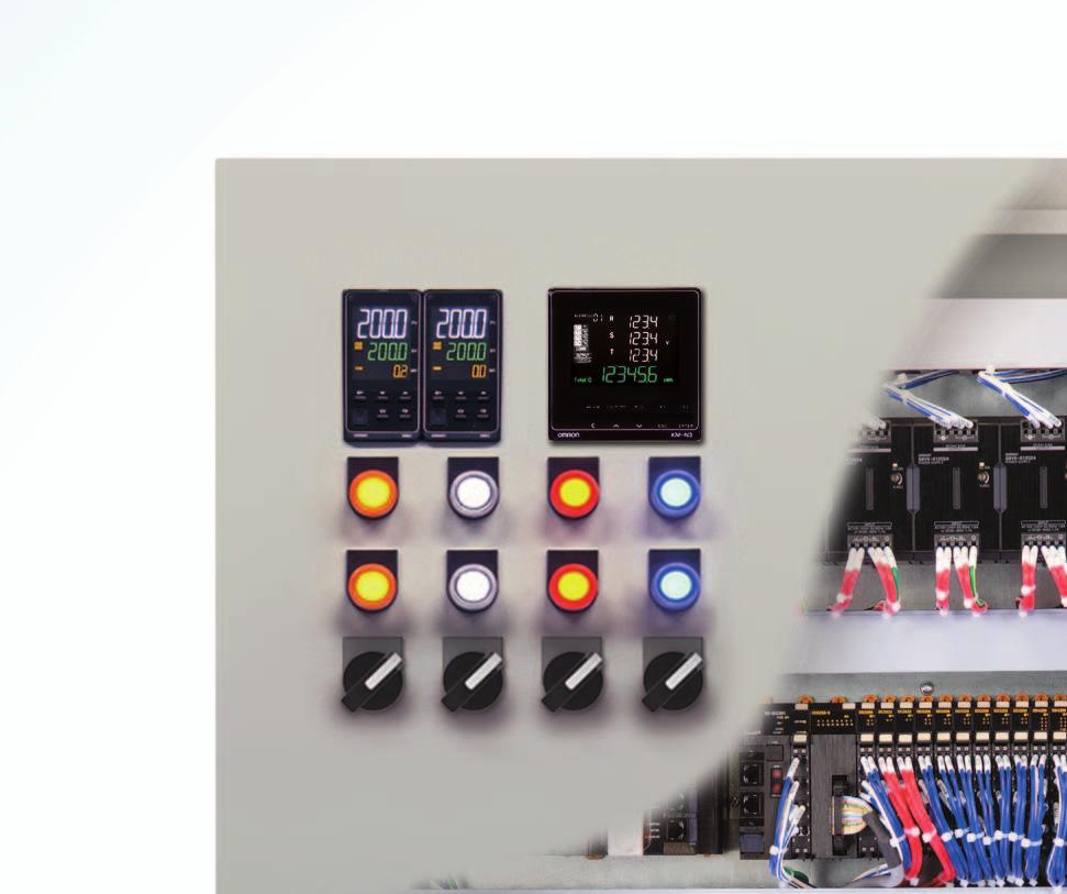
1 New Value For Control Panels Power Monitors / Multi-circuit Power Monitors for Energy Management Easily Implement All Types of Power Monitoring with On-panel and In-panel Installation Power Monitors applicable around the globe Solve design, installation, and operation topics with one model for each installation type Handle circuits up to 3-phase 4-wire and 3-phase 480 V


2 2 New Value For Control Panels Control Panels: The Heart of Manufacturing Sites. Evolution in control panels results in large evolution in production facilities. And if control panel design, control panel manufacturing processes, and human interaction with them are innovated, control panel manufacturing becomes simpler and takes a leap forward. OMRON will continue to achieve a control panel evolution and process innovation through many undertakings starting with the shared Value Design for Panel *1 concept for the specifications of products used in control panels. *1 Value Design for Panel Our shared Valu ue Design for Panel (herein afterr referred to as "Value De esign") concept for the specifica ations of products used in n control panels will create new w value to our customer s ccontrol panels. Combining multiple products that share the Value Design concept will furth her increase the value provided to o control panels. Innovation for panel building Process Further Evolution for Panels New Value For Control Panels Simple Easy for panel business People


 Four Total Power")

3 Multi-circuit Power Monitors for Energy Management Easily Implement All Types of Power Monitoring with On-panel and In-panel Installation 3 The New and Power Monitors Energy management starts by continuously monitoring power. The KN-N2 and KN-N3 enable all types of power measurement with easy installation and easy system construction. You can mount them on or in control panels and distribution boards and take advantage of their compatibility with power supplies around the world. Multi-circuit measurements Three-phase 4-wire Three-phase 3-wire Single-phase 3-wire Single-phase 2-wire 1-circuits 2-circuits 4-circuits Single-phase 100 V to Three-phase 480 V General-purpose CT (1 A or 5 A) Packed Full of Functions! Modbus/RTU (RS-485) Four Total Power Consumption Pulse Outputs IEC Class 0.5S Accuracy Corresponding to the Main International Standards Note: Certification of the is pending.


4 4 Power Monitors / Features Common to Both the and Power Monitors for Energy Management That Easier Application and Greater Work Efficiency for Everyone System Design Manager * Handle All EMS Specifications Energy Manager No Numeric Value *EMS: Energy Management System General-purpose CTs Large Easy-to-read Displays Actual Size Corresponding to the Main International Standards Note: Certification of the is pending. Many Host Communications Methods PLC Proprietary systems Central monitoring system RS-485 communications Modbus(RTU) CompoWay/F Multi-address System Total power consumption pulse outputs DIN Rail Installation Type Address Setting 02 Threephase, 3-wire Automatic assignment 03 Setting Threephase, 3-wire Singlephase, 3-wire Automatic assignment Singlephase, 2-wire Singlephase, 2-wire Setting 09 Threephase, 4-wire 3-wire


5 5 Solve Design,Installation, and Operation Issues Overlooked Installation Manager Efficient Wiring Actual Size Push-In Plus Terminal Block The structure of Push-In Plus terminal blocks helps reduce wiring mistakes with easy-to-insert terminals that hold wires firmly (RS-485 communications and pulse output terminals). On-panel Installation Type Wiring Error Detection ALARM lamp blinks! lamp lights up
.")
6 Power Monitor -FLK Global Power Monitor for Mounting Inside Control Panels Solve design, installation, and operation topics. You can measure up to four circuits with one Power Monitor. Use general-purpose CTs and handle a variety of worksites. Large, easy-to-read white LCD for improved visibility. IEC Class 0.5S high-precision measurements (Power Monitor only). Refer to Safety Precautions on page 19. For the most recent information on models that have been certified for safety standards, refer to your OMRON website. Ordering Information Power Monitor -FLK Model Applicable phase wiring methods Power supply voltage Dimensions Communications Single-phase, 2-wire: 100 to 277 VAC Single-phase, 3-wire: 100 to 240 VAC (L-N) or 200 to 480 VAC (L-L) Three-phase, 3-wire: 173 to 480 VAC (L-L) Three-phase, 4-wire: 100 to 277 VAC (L-N) or 173 to 480 VAC (L-L) To use a commercially available current transformer, use a CT with a secondary current rating of 1 A or 5 A, and a rated load of at least 1.0 VA. Connectable OMRON Split-type Current Transformers (CTs) Note: The CT cable is connected to the CT (cable length: 1 m). Same as measured circuits: 100 to 277 VAC (L-N) 173 to 480 VAC (L-L) Model Rated primary current Rated secondary current KM20-CTN A KM20-CTN A 1 A KM20-CTN A mm (H W D) RS-485 communications, pulse output Specifications Ratings (Power Monitor) Item Model -FLK Applicable phase wiring methods Number of measured circuits Power consumption Input Rated input voltages (power supply voltages) Allowable supply voltage range Single-phase two-wire, single-phase three-wire, three-phase three-wire, and three-phase four-wire Single-phase two-wire: 4 circuits max., Single-phase three-wire or three-phase three-wire: 2 circuits max., Three-phase four-wire: 1 circuit 7 VA max. Single-phase, 2-wire: 100 to 277 VAC Single-phase, 3-wire: 100 to 240 VAC (L-N) or 200 to 480 VAC (L-L) Three-phase, 3-wire: 173 to 480 VAC (L-L) Three-phase, 4-wire: 100 to 277 VAC (L-N) or 173 to 480 VAC (L-L) 85% to 115% of rated power supply voltage Connectable CTs General-purpose CT with a rated secondary current of 1 A or 5 A * Maximum CT secondary current Rated input frequency Ambient operating temperature 6 A 50/60 Hz Ambient operating humidity 25% to 85% Storage temperature Storage humidity 25% to 85% Operating altitude 25 to 55 C (with no condensation or icing) 25 to 85 C (with no condensation or icing) 2,000 m max. Installation environment Overvoltage category II, measurement category II, pollution degree 2 Electromagnetic environment Industrial electromagnetic environment (EN/IEC Table 2) Compliant standards EN , EN , and UL * The KM-series CTs (the KM20-CTF or KM-NCT Series) cannot be used. Use general-purpose CTs with a secondary-side output of 1 A or 5 A. 6
7 -FLK Ratings (Connectable OMRON Split-type Current Transformers (CTs)) Item Model KM20-CTN100 KM20-CTN250 KM20-CTN500 Rated primary current 100 A 250 A 500 A Rated secondary current 1 A 1 A 1 A Rated frequency Insulation resistance Dielectric strength Cable length Performance (Power Monitor) 50/60 Hz 100 MΩ min. (at 500 VDC) (Between through hole and output lead) 2000V AC 1min. (Between through hole and output lead) 1 m Through-hole 24 diameter 36 diameter Weight Approx. 210 g Approx. 500 g Operating temperature and humidity ranges Storage temperature and humidity ranges 20 to 55 C, 85% max. relative humidity (with no condensation) 30 to 90 C, 85% max. relative humidity (with no condensation) Item Model -FLK Measured items Measurement specifications Total power consumption (active, regenerative, and reactive), power (active and reactive), current, voltage, power factor, and frequency Active power 0.5% (IEC class 0.5S) * Reactive power 2% (IEC class 2) * Sampling cycle 80 ms for 50 Hz and 66.7 ms for 60 Hz (1) Between all electrical circuits and the case: 20 MΩ min. (at 500 VDC) Insulation resistance (2) Between all power supply and voltage inputs and all communications and pulse output terminals: 20 MΩ max. (at 500 VDC) Dielectric strength (1) Between all electrical circuits and the case: 2,200 VAC for 1 min (2) Between all voltage and current inputs and all communications and pulse output terminals: 2,200 VAC for 1 min Vibration resistance Single amplitude: 0.1 mm, Acceleration: 15 m/s 2, Frequency: 10 to 150 Hz, 10 sweeps for 8 min each along three axes Shock resistance 150 m/s 2, 3 times each in 6 directions (up/down, left/right, forward/backward) Indications and operation method LED/LCD indications and operation buttons Weight Approx. 350 g (Power Monitor only) Degree of protection IP20 Number of outputs Number of outputs: 4 (photomos relay outputs) Used for the total power consumption pulse output. Pulse output Output capacity 50 ma at 40 VDC ON residual voltage: 1.5 V max. (for output current of 50 ma) OFF leakage current: 0.1 ma max. Output unit Output unit: 1, 10, 100, 1k, 5k, 10k, 50k, or 100k (wh) Pulse ON time: 500 ms (Cannot be changed.) Communications method RS-485 (2-wire half-duplex with start-stop synchronization) Communications protocol Modbus (RTU): Binary. CompoWay/F: ASCII Baud rate 1.2, 2.4, 4.8, 9.6, 19.2, or 38.4 kbps Data length: 7 or 8 bits Communications Data length Stop bits: 1 or 2 bits interface Vertical parity: Even, odd, or none Maximum transmission distance 1,200 m Dimensions (H W D) Installation method Accessories Maximum number of connected Power Monitors Modbus: 99, CompoWay/F: 31 If you measure more than one circuit with one Power Monitor, the number of circuits is treated as the number of connected Power Monitors mm (excluding protrusions) DIN Rail mounting Instruction Manual and Compliance Sheet * The error of the CT or VT is not included. IEC is an international standard for power metering. 7
 (14) (23) (22) No. Item Description (1) Power indicator (green) Lights when the power supply is turned ON. (2) Error indicator (red) Flashes when there is an abnormality, such as a failure.")
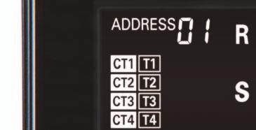
8 -FLK Part Names and Functions Power Monitor Front Panel with Terminal Block Covers Removed Detailed View of LCD Side View (16) (17) (18) (6) (7) (22) (1) (2) (3) (4) (5) (15) (8) (11) (12) (13) (9) (10) (14) (23) (22) No. Item Description (1) Power indicator (green) Lights when the power supply is turned ON. (2) Error indicator (red) Flashes when there is an abnormality, such as a failure. (3) Alarm indicator (orange) Flashes when there is an alarm. (4) Communications indicator (yellow) Lit during communications. (5) Pulse indicator (yellow) Lit while pulses are being output from OUT1 (circuit A). (6) (7) Communications address and menu display Status Indicators When ADDRESS is lit (Measurement Mode), the communications address is being displayed. When MENU is lit (Setting Mode), the menu number is being displayed. SET Lit in Setting Mode. OUTPUT Lit while a pulse output is being set up. 1 Lit while pulses are being output from OUT1. 2 Lit while pulses are being output from OUT2. 3 Lit while pulses are being output from OUT3. 4 Lit while pulses are being output from OUT4. Measured Main display Displays the measured value or set value. (8) value/set value display Sub display Displays the measurement unit or setting name. (9) Tariff display Displays the tariff number (T1 to T4) a total active power consumption is being saved. (10) CT usage display Displays the numbers of the CTs (CT1 to CT4) for which measurement or setting operations are in progress. (11) <</MODE Key Short press: Changes the circuit or moves the digit. Long press: Changes the mode. (12) Key Increments the item or value. (13) Key Decrements the item or value. (14) ENTER Key Enters the item or value. (15) ESC Key Cancel (16) Rotary switches Set the communications address for circuit A. The left switch (x10) sets the tens place and the right switch (x1) sets the ones place. (17) RS-485 communications terminals (19) (21) (20) RS (1) RS terminal RS-485 (1) RS-485 terminal RS (2) RS terminal for crossover wiring RS-485 (2) RS-485 terminal for crossover wiring RS-485 E RS-485 terminating resistance terminal OUT1 Pulse output terminal for circuit A OUT2 Pulse output terminal for circuit B (18) Pulse output terminals OUT3 Pulse output terminal for circuit C OUT4 Pulse output terminal for circuit D COM Pulse output common terminal (19) Voltage input terminals Terminal used to input the power supply voltage. These terminals are also used for the measured voltage inputs. (20) CT input terminals Terminals used to connect the CT cables for CT1 to CT4 (21) DIN hook Hook used to mount the Power Monitor to a DIN Track (22) Terminal block covers Sealed terminal block covers (23) Terminal arrangement label Label that provides information, such as the model number, power supply voltage, terminal arrangement, and serial number 8
9 Connection Wiring Diagrams -FLK Three-phase, Four-wire Circuit CT Wiring Examples side RSTN side Branch circuit breaker V1 V2 V3 VN CT1 CT2 CT3 CT4 Single-phase, Two-wire Circuit Branched from Singlephase, Three-wire Circuit R N T Circuit A (CT1) Circuit B (CT2) Circuit C (CT3) Circuit D (CT4) Branch circuit breaker V1 V2 V3 VN CT1 CT2 CT3 CT4 Single-phase, Three-wire Circuit Circuit A (CT1 and CT2) Circuit C (CT3 and CT4) R N T side Branch circuit breaker V1 V2 V3 VN CT1 CT2 CT3 CT4 side Single-phase, Three-wire Circuit and Single-phase, Two-wire Circuit Branched from Single-phase, Three-wire Circuit RN T Circuit A (CT1 and CT2) Circuit C (CT3) Circuit D (CT4) side Branch circuit breaker V1 V2 V3 VN CT1 CT2 CT3 CT4 Three-phase, Three-wire Circuit Single-phase, Two-wire Circuit Circuit A (CT1 and CT2) RST Branch circuit breaker V1 V2 V3 VN Circuit A (CT1) L N Branch circuit breaker V1 V2 V3 VN Circuit C (CT3 and CT4) side CT1 CT2 CT3 CT4 Circuit B (CT2) Circuit C (CT3) Circuit D (CT4) CT1 CT2 CT3 CT4 side CT Wiring For each circuit, one CT is required to measure single-phase two-wire power, two CTs are required to measure single-phase three-wire power or three-phase three-wire power, and three CTs are required to measure three-phase four-wire power. Use AWG18 to AWG14 (cross-sectional area: 0.75 to 2.0 mm 2 ) wires with a heat resistance of 85 C min. to connect to the CT input terminals. Use ferrules suitable for the wire diameter to connect to the CT input terminals. The recommended tightening torque for M3 terminal screws is 0.5 to 0.6 N m. Push ferrules all the way in and tighten the screws securely. Voltage Wiring (Power supply voltage and measurement voltage are shared.) The Power Monitor has voltage input terminals V1, V2, V3, and VN, which function as both the operating power supply terminals and voltage measurement terminals. Connect a branch circuit breaker between the voltage input terminals and the wiring so that the power supply can be turned OFF immediately. For safety, always work with the power supply turned OFF both at the main power supply and at the branch circuit breaker. Connect the wires in the correct phase sequence. Otherwise, the power and power consumption cannot be measured correctly. When wiring the power supply and measured voltage terminals, use round or forked crimp terminals (6.7 mm wide or less) suitable for M3.5 screws and AWG24 to AWG14 (cross-sectional area: 0.2 to 2.0 mm 2 ) wires. Recommended tightening torque for M3.5 terminal screws: 0.8 N m. Push crimp terminals all the way in and tighten the screws securely After securing the wiring, gently pull on the cables to check that they are held securely. Always use the Power Monitor with the terminal covers closed. 9
10 -FLK Wiring Diagram The following table shows the relationship between the wire phases connected to the voltage input terminals and CT input terminals for each phase wiring method. Single-phase, 2-wire Single-phase, 3-wire Three-phase, 3-wire Three-phase, 4-wire Phase wires connected to voltage input terminals Phase wires connected to CT input terminals Number of measured circuits V1 V2 V3 VN CT1 CT2 CT3 CT4 Phase L (VR) Phase N (VN) Phase L 1 Phase L 2 Phase L 3 Phase L 4 4 Phase R (VR) --- Phase T (VT) Phase N (VN) Phase R 1 Phase T 1 Phase R 2 Phase T 2 2 Phase R (VR) Phase S (VS) Phase T (VT) --- Phase R 1 Phase T 1 Phase R 2 Phase T 2 2 Phase R (VR) Phase S (VS) Phase T (VT) Phase N (VN) Phase R Phase S Phase T Note: The numbers in phase L 1 and phase L 2 indicate the number of the circuit. RS-485 Communications Wiring Diagram The connection configuration is 1:1 or 1:N. For a 1:N configuration, up to 99 nodes can be connected for Modbus and up to 31 nodes can be connected for CompoWay. If you measure more than one circuit with one Power Monitor, the number of circuits is treated as the number of connected Power Monitors. The terminal block has push-in terminals. When wiring, observe the Precautions for Correct Use in Wires and Precautions for Using Push-in Plus Terminal Blocks (RS-485 Communications Terminals and Pulse Output Terminals). The does not have a FG terminal. Connect only the positive and negative lines for RS-485. Use twisted-pair cables. Wire the RS-485 communications lines and power lines separately to prevent the influences of noise. The maximum transmission distance is 1,200 m. Always test communications on the actual system regardless of the transmission distances and number of connected Power Monitors. Always close the terminal block covers before you use the Power Monitor. Communications Address Setting Turn the rotary switches for the 1s and 10s positions and set the communications address for circuit A. The value on the rotary switches is assigned as the communications address for circuit A (1st circuit). When multiple addresses are used, the values given in the following table are allocated automatically. The communications addresses for circuit B through circuit D cannot be set individually. + Communications master (host) 1st Power Monitor 2nd Power Monitor Nth Power Monitor Rotary switch for 10s position Rotary switch for 1s position Circuit A Circuit B Circuit C Circuit D Three-phase, four-wire Set value Single-phase, two-wire circuit branched from single-phase, twowire circuit or single-phase, three-wire circuit Set value Set value +1 Set value +2 Set value +3 Single-phase, three-wire circuit or three-phase, three-wire circuit Set value --- Set value Single-phase, three-wire circuit and single-phase, two-wire circuit branched from single-phase, three-wire circuit Set value --- Set value +1 Set value +2 Terminating Resistance Setting The Power Monitor has terminating resistance built in. On the last node on the communications line, connect a jumper between the RS-485 negative terminal and the RS-485 E terminal. The internal terminating resistance will be connected. When using a host that does not have built-in terminating resistance, connect terminating resistance to the host as well. The terminating resistance is 120 Ω (1/2 W). Do not wire terminating resistance to the partway along the transmission path. Communications failures may occur. Jumper 10
11 Pulse Output Wiring Diagrams -FLK NPN Output Connection Diagram PNP Output Connection Diagram + + OUT1 OUT2 OUT3 OUT4 COM OUT1 OUT2 OUT3 OUT4 COM The Power Monitor provides four pulse output terminals. One common is used. The terminal block has push-in terminals. When wiring, observe the Precautions for Correct Use in Wires and Precautions for Using Push-in Plus Terminal Blocks (RS-485 Communications Terminals and Pulse Output Terminals). Never connect an external power supply directly between an output terminal and the common. Always connect a load. Wire signal lines and power lines separately to prevent the influences of noise. The outputs are assigned as follows and cannot be changed: OUT1 is for circuit A, OUT2 is for circuit B, OUT3 is for circuit C, and OUT4 is for circuit D. Dimensions Power Monitor -FLK (Unit: mm) Moving range of part A R20.3 (41.2) DIN Track 45 Part A 90 (49) 5 43 Part B Moving range of part A R Moving range of part B KM20-CTN100 KM20-CTN250 KM20-CTN500 4 W W1 22 Dia. d K L H1 H2 H3 k: White l: Black 0.75 mm 2-2C (white): k 1000L (black): l Dimension (mm) Dia. d W1 W2 H1 H2 H3 KM20-CTN KM20-CTN KM20-CTN
.")
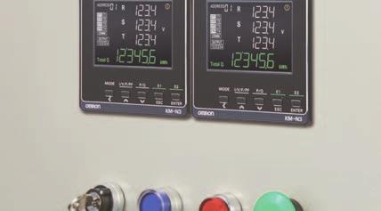
12 Power Monitor -FLK Global Power Monitor for On-panel Installation Solve design, installation, and operation topics. You can measure up to four circuits with one Power Monitor. Use general-purpose CTs and handle a variety of worksites. Large, easy-to-read white and green LCD for improved visibility. IEC Class 0.5S high-precision measurements (Power Monitor only). Refer to Safety Precautions on page 19. For the most recent information on models that have been certified for safety standards, refer to your OMRON website. Ordering Information Power Monitor -FLK Model Applicable phase wiring methods Power supply voltage Dimensions Communications Single-phase, 2-wire: 100 to 277 VAC Single-phase, 3-wire: 100 to 240 VAC (L-N) or 200 to 480 VAC (L-L) Three-phase, 3-wire: 173 to 480 VAC (L-L) Three-phase, 4-wire: 100 to 277 VAC (L-N) or 173 to 480 VAC (L-L) 100 to 240 VAC Separate from measurement voltage mm (H W D) (excluding protrusions) To use a commercially available current transformer, use a CT with a secondary current rating of 1 A or 5 A, and a rated load of at least 1.0 VA. RS-485 communications, pulse output Optional Products (Order Separately) Terminal Covers Model E53-COV24 (3pcs) Waterproof Packing Mounting Adapter Model Y92F-51 (2pcs) Note: This Mounting Adapter is provided with the. Model Y92S-P10 Note: This Waterproof Packing is provided with the. Connectable OMRON Split-type Current Transformers (CTs) Model Rated primary current Rated secondary current KM20-CTN A KM20-CTN A 1 A KM20-CTN A Note: The CT cable is connected to the CT (cable length: 1 m). 12
13 Specifications Ratings (Power Monitor) -FLK Item Model -FLK Applicable phase wiring methods Single-phase two-wire, single-phase three-wire, three-phase three-wire, and three-phase four-wire Number of measured circuits Single-phase two-wire: 4 circuits max., Single-phase three-wire or three-phase three-wire: 2 circuits max., Three-phase four-wire: 1 circuit Power supply voltage (operating frequency) 100 to 240 VAC (50/60 Hz) Power supply allowable voltage range 85% to 110% of rated power supply voltage Power consumption 7 VA max. Single-phase, 2-wire: 100 to 277 VAC Rated input voltages Single-phase, 3-wire: 100 to 240 VAC (L-N) or 200 to 480 VAC (L-L) Three-phase, 3-wire: 173 to 480 VAC (L-L) Three-phase, 4-wire: 100 to 277 VAC (L-N) or 173 to 480 VAC (L-L) Input Allowable supply voltage range 85% to 115% of rated power supply voltage Connectable CTs General-purpose CT with a rated secondary current of 1 A or 5 A * Maximum CT secondary current 6 A Rated input frequency 50/60 Hz Ambient operating temperature 25 to 55 C (with no condensation or icing) Ambient operating humidity 25% to 85% Storage temperature 25 to 85 C (with no condensation or icing) Storage humidity 25% to 85% Operating altitude 2,000 m max. Installation environment Overvoltage category II, measurement category II, pollution degree 2 Electromagnetic environment Industrial electromagnetic environment (EN/IEC Table 2) Compliant standards EN , EN , and UL (pending) * The KM-series CTs (the KM20-CTF or KM-NCT Series) cannot be used. Use general-purpose CTs with a secondary-side output of 1 A or 5 A. Ratings (Connectable OMRON Split-type Current Transformers (CTs)) Item Model KM20-CTN100 KM20-CTN250 KM20-CTN500 Rated primary current 100 A 250 A 500 A Rated secondary current 1 A 1 A 1 A Rated frequency 50/60 Hz Insulation resistance 100 MΩ min. (at 500 VDC) (Between through hole and output lead) Dielectric strength 2000V AC 1min. (Between through hole and output lead) Cable length 1 m Through-hole 24 diameter 36 diameter Weight Approx. 210 g Approx. 500 g Operating temperature and humidity ranges 20 to 55 C, 85% max. relative humidity (with no condensation) Storage temperature and humidity ranges 30 to 90 C, 85% max. relative humidity (with no condensation) Performance (Power Monitor) Item Model -FLK Measured items Total power consumption (active, regenerative, and reactive), power (active and reactive), current, voltage, power factor, and frequency Active power 0.5% (IEC class 0.5S * Measurement Reactive power 2% (IEC class 2) * specifications Sampling cycle 80 ms for 50 Hz and 66.7 ms for 60 Hz (1) Between all electrical circuits and the case: 20 MΩ min. (at 500 VDC) Insulation resistance (2) Between all power supply and voltage inputs and all communications and pulse output terminals: 20 MΩ max. (at 500 VDC) Dielectric strength (1) Between all electrical circuits and the case: 1,400 VAC for 1 min (2) Between all voltage and current inputs and all communications and pulse output terminals: 2,200 VAC for 1 min Vibration resistance Single amplitude: 0.1 mm, Acceleration: 15 m/s 2, Frequency: 10 to 150 Hz, 10 sweeps for 8 min each along three axes Shock resistance 150 m/s 2, 3 times each in 6 directions (up/down, left/right, forward/backward) Indications and operation method LCD indications and operation buttons Weight Approx. 350 g (Power Monitor only) Degree of protection Front: IP65, Rear case: IP20, Terminal: IP00 Number of outputs Number of outputs: 4 (photomos relay outputs) Used for the total power consumption pulse output. 50 ma at 40 VDC Pulse output Output capacity ON residual voltage: 1.5 V max. (for output current of 50 ma) OFF leakage current: 0.1 ma max. Output unit Output unit: 1, 10, 100, 1k, 5k, 10k, 50k, or 100k (wh) Pulse ON time: 500 ms (Cannot be changed.) Communications method RS-485 (2-wire half-duplex with start-stop synchronization) Communications protocol Modbus (RTU): Binary. CompoWay/F: ASCII Baud rate 1.2, 2.4, 4.8, 9.6, 19.2, or 38.4 kbps Data length: 7 or 8 bits Communications Data length Stop bits: 1 or 2 bits interface Vertical parity: Even, odd, or none Maximum transmission distance 1,200 m Modbus: 99, CompoWay/F: 31 Maximum number of connected If you measure more than one circuit with one Power Monitor, the number of circuits is treated as the number Power Monitors of connected Power Monitors. Dimensions (H W D) mm (excluding protrusions) Installation method On-panel installation Accessories Instruction Manual and Compliance Sheet, Mounting adapter and waterproof packing * The error of the CT or VT is not included. IEC is an international standard for power metering. 13
14 -FLK Part Names and Functions Power Monitor Front LCD display details Right side surface Rear Left side surface (8) (10) (9) (20) (13) (7) (8) (9) (14) (16) (11) (12) (15) (17) (1) (2) (3) (4) (5) (19) (18) (20) No. Item Description (1) MODE key (2) I/V/F/PF key (3) P/Q key (4) E1 ESC key (5) E2 ENTER key Long press: The measurement mode is switched with the setup mode. [MODE] key (measurement mode): The measurement circuit is changed. [ ] key (setup mode): Change of the measurement circuit / Digit shifting when a numerical value is input [I/V/F/PF] key (measurement mode): The display of current, voltage, frequency, or power factor is switched. [ ] key (setup mode): Items or values are changed (up) [P/Q] key (measurement mode): The display of effective power or reactive power is switched. [ ] key (setup mode): Items or values are changed (down) [ESC] key (measurement mode): Cancel [E1] key (setup mode): The display of each integrated electric energy is switched. [ENTER] key (measurement mode): Select/Determine [E2] key (setup mode): The display of each resettable integrated electric energy is switched. (6) Communication address / When ADDRESS is lit (in the measurement mode): The communication address is displayed. Menu display When MENU is lit (in the setup mode): The menu number is displayed. (7) In-operation CT display The CT number in the condition of measurement or setup (CT1 to CT4) is displayed. (8) Tariff display The tariff number which is saving the integrated effective energy (T1 to T4) is displayed. (9) State display (10) Measured value display / Setup value display COMM Blinks when RS-485 communications are in progress. OUTPUT Lit when the pulse output is set. 1 Lit when pulse is output from OUT 1. 2 Lit when pulse is output from OUT 2. 3 Lit when pulse is output from OUT 3. 4 Lit when pulse is output from OUT 4. SET Lit in the setup mode. Blinks when a warning occurs. First display / instantaneous value display Second display / Integrated value display Instantaneous values or setup values are displayed (on rows No. 1-3). The integrated value is displayed (on row No. 4). RESETTABLE Lit when resettable integrated electric energy is displayed. (11) Measurement auxiliary display --- Lit when integrated leading reactive electric energy is displayed. Total Q Lit when total integrated reactive electric energy is displayed. (12) Unit display The unit of each measured value is lit. (13) Power supply terminal Power supply voltage is input to this terminal (14) RS-485 communication terminal RS (1) RS-485 (1) RS (2) RS-485 (2) RS-485E RS terminal RS terminal RS terminal (for transition wiring) RS terminal (for transition wiring) RS-485 terminating resistor terminal OUT1 Circuit A pulse output terminal OUT2 Circuit B pulse output terminal (15) Pulse output terminal OUT3 Circuit C pulse output terminal OUT4 Circuit D pulse output terminal COM Common terminal for outputting pulse (16) CT input terminal Terminal to connect the CT cable for CT1 to CT4 (17) Measured voltage input terminal Measured voltage is input to this terminal. (18) Terminal array label Model, power supply voltage, terminal array, serial number, and so on are written on this label. (19) Wiring label A wiring diagram of voltage and current is written on this label. (20) Mounting adapter Adapter to fix the main unit to the panel 14
15 Connection Wiring Diagrams -FLK Three-phase, Four-wire Circuit CT Wiring Examples side RSTN side V1 L+ V2 N- V3 VN CT1 CT2 CT3 CT4 Single-phase, Two-wire Circuit Branched from Singlephase, Three-wire Circuit Circuit A (CT1) Circuit B (CT2) Circuit C (CT3) Circuit D (CT4) R N T V1 L+ V2 N- V3 VN CT1 CT2 CT3 CT4 Single-phase, Three-wire Circuit Circuit A (CT1 and CT2) Circuit C (CT3 and CT4) R N T V1 L+ V2 N- V3 VN CT1 CT2 CT3 CT4 side Single-phase, Three-wire Circuit and Single-phase, Two-wire Circuit Branched from Single-phase, Three-wire Circuit Circuit A (CT1 and CT2) Circuit C (CT3) Circuit D (CT4) RN T V1 L+ V2 N- V3 VN CT1 CT2 CT3 CT4 side Three-phase, Three-wire Circuit side Single-phase, Two-wire Circuit Circuit A (CT1 and CT2) Circuit C (CT3 and CT4) RST V1 L+ V2 N- V3 VN CT1 CT2 CT3 CT4 Circuit A (CT1) Circuit B (CT2) Circuit C (CT3) Circuit D (CT4) L N V1 L+ V2 N- V3 VN CT1 CT2 CT3 CT4 side side CT Wiring For each circuit, one CT is required to measure single-phase two-wire power, two CTs are required to measure single-phase three-wire power or three-phase three-wire power, and three CTs are required to measure three-phase four-wire power. Use AWG18 to AWG14 (cross-sectional area: 0.75 to 2.0 mm 2 ) wires and round or forked crimp terminals (5.8 mm wide or less) suitable for M3 screws to connect to the CT input terminals. The recommended tightening torque for M3 terminal screws is 0.5 to 0.58 N m. Push crimp terminals all the way in and tighten the screws securely. After you secure the wires, confirm that they are securely held in place. Power Supply Wiring For safety, always turn OFF the main power supply and work while no power is supplied. The terminal block has push-in terminals. When wiring, observe the Precautions for Correct Use in Wires and Precautions for Using Push-in Plus Terminal Blocks (RS-485 Communications Terminals and Pulse Output Terminals). Wiring Measurement Voltages For safety, always work with the power supply turned OFF both at the main power supply. Connect the wires in the correct phase sequence. Otherwise, the power and power consumption cannot be measured correctly. When wiring the measured voltage terminals, use round or forked crimp terminals (5.8 mm wide or less) suitable for M3 screws and AWG18 to AWG14 (cross-sectional area: 0.75 to 2.0 mm 2 ) wires. Recommended tightening torque for M3 terminal screws: 0.5 to 0.58 N m. Push crimp terminals all the way in and tighten the screws securely After securing the wiring, gently pull on the cables to check that they are held securely. 15
16 -FLK Wiring Diagram The following table shows the relationship between the wire phases connected to the voltage input terminals and CT input terminals for each phase wiring method. Phase wires connected to voltage input terminals Phase wires connected to CT input terminals Number of V1 V2 V3 VN CT1 CT2 CT3 CT4 measured circuits Single-phase, 2-wire Phase L (VR) Phase N (VN) Phase L 1 Phase L 2 Phase L 3 Phase L 4 4 Single-phase, 3-wire Phase R (VR) --- Phase T (VT) Phase N (VN) Phase R 1 Phase T 1 Phase R 2 Phase T 2 2 Three-phase, 3-wire Phase R (VR) Phase S (VS) Phase T (VT) --- Phase R 1 Phase T 1 Phase R 2 Phase T 2 2 Three-phase, 4-wire Phase R (VR) Phase S (VS) Phase T (VT) Phase N (VN) Phase R Phase S Phase T Note: The numbers in phase L 1 and phase L 2 indicate the number of the circuit. RS-485 Communications Wiring Diagram The connection configuration is 1:1 or 1:N. For a 1:N configuration, up to 99 nodes can be connected for Modbus and up to 31 nodes can be connected for CompoWay. If you measure more than one circuit with one Power Monitor, the number of circuits is treated as the number of connected Power Monitors. The terminal block has push-in terminals. When wiring, observe the Precautions for Correct Use in Wires and Precautions for Using Push-in Plus Terminal Blocks (RS-485 Communications Terminals and Pulse Output Terminals). Communications master (host) + - 1st Power Monitor 2nd Power Monitor Nth Power Monitor (Termination) Jumper The does not have a FG terminal. Connect only the positive and negative lines for RS-485. Use twisted-pair cables. Wire the RS-485 communications lines and power lines separately to prevent the influences of noise. The maximum transmission distance is 1,200 m. Always test communications on the actual system regardless of the transmission distances and number of connected Power Monitors. Communications Address Setting Change to Setting Mode and set the communications address for circuit A. Refer to the Instruction Manual for the communications address setting method. If the multi-address function is used, the addresses in the following table are automatically allocated based on the communications address set for circuit A (the first circuit). The communications addresses for circuit B through circuit D cannot be set individually. Circuit A Circuit B Circuit C Circuit D Three-phase, four-wire Set value Single-phase, two-wire circuit branched from single-phase, twowire circuit or single-phase, three-wire circuit Set value Set value +1 Set value +2 Set value +3 Single-phase, three-wire circuit or three-phase, three-wire circuit Set value --- Set value Single-phase, three-wire circuit and single-phase, two-wire circuit branched from single-phase, three-wire circuit Set value --- Set value +1 Set value +2 Terminating Resistance Setting The Power Monitor has terminating resistance built in. On the last node on the communications line, connect a jumper between the RS-485 negative terminal and the RS-485 E terminal. The internal terminating resistance will be connected. When using a host that does not have built-in terminating resistance, connect terminating resistance to the host as well. The terminating resistance is 120 Ω (1/2 W). Do not wire terminating resistance to the partway along the transmission path. Communications failures may occur. 16
17 Pulse Output Wiring Diagrams -FLK NPN Output Connection Diagram PNP Output Connection Diagram + + OUT1 OUT2 OUT3 OUT4 COM OUT1 OUT2 OUT3 OUT4 COM The Power Monitor provides four pulse output terminals. One common is used. The terminal block has push-in terminals. When wiring, observe the Precautions for Correct Use in Wires and Precautions for Using Push-in Plus Terminal Blocks (RS-485 Communications Terminals and Pulse Output Terminals). Never connect an external power supply directly between an output terminal and the common. Always connect a load. Wire signal lines and power lines separately to prevent the influences of noise. The outputs are assigned as follows and cannot be changed: OUT1 is for circuit A, OUT2 is for circuit B, OUT3 is for circuit C, and OUT4 is for circuit D. Dimensions Power Monitor -FLK (Unit: mm) Panel cut-out dimensions for mountin KM20-CTN100 KM20-CTN250 KM20-CTN500 4 W W1 22 Dia. d K L H1 H2 H3 k: White l: Black 0.75 mm 2-2C (white): k 1000L (black): l Dimension (mm) Dia. d W1 W2 H1 H2 H3 KM20-CTN KM20-CTN KM20-CTN
18 -FLK Optional Products (Order Separately) Terminal Covers E53-COV24 (Three Covers provided.) Waterproof Packing Y92S-P10 (for DIN 96 96) The Waterproof Packing is provided with the. Order the Waterproof Packing separately if it becomes lost or damaged. The Waterproof Packing for the front-panel Setup Tool port must be periodically replaced because they may deteriorate, shrink, or harden depending on the operating environment. The replacement period will vary with the operating environment. Check the required period in the actual application. Use 3 years or sooner as a guideline. Mounting Adapter Y92F-51 (Two Adapters provided.) One pair is provided with the. Order this Adapter separately if it becomes lost or damaged. 18
19 Safety Precautions Warning Indications CAUTION Property damage may occasionally occur due to fire. Tighten terminal screws to the specified tightening torque. Confirm that there is no looseness in the screws after tightening them. M3.5 screws: 0.8 N m M3 screws: 0.5 to 0.6 N m (), 0.5 to 0.58 N m () Minor or moderate bodily harm or property damage may occasionally occur due to explosion. Do not use the Power Monitor near inflammable or explosive gas. Destruction or rupture may occasionally occur. Make sure that the power supply voltages and loads are within specifications and ratings. Electrical shock may occasionally occur. Do not touch any of the terminals while the power is being supplied. Electric shock may occasionally occur. Always turn OFF the power supply to the circuit where a CT is mounted before you connect the CT terminals on the Power Monitor. Electrical shock, minor injury, fire, or equipment malfunction may occasionally occur. Do not apply a current that exceeds the maximum current for the CT secondary side to the CT input terminals. Electrical shock, minor injury, fire, or equipment malfunction may occasionally occur. Do not disassemble, repair, or modify the Power Monitor. * CT: Current transformer Indicates a potentially hazardous situation which, if not avoided, may result in minor or moderate injury or in property damage. Caution Meaning of Warning Symbols on the Electric shock may occasionally occur. Use wires with a heat resistance of 85 C min. to connect to the voltage input, CT input, and communications terminals. -FLK/-FLK Precautions for Safe Use Observe the following precautions to ensure the safe usage of the /N3. Do not store, install, or use the Power Monitor in the following locations. Locations that are greatly affected by vibration or shock Unstable locations Locations where the specified range of temperature or humidity would be exceeded Locations that are subject to rapid changes in temperature or humidity where condensation or icing may occur Outdoors or locations that are subject to direct sunlight, wind, or rain Locations that are affected by static electricity or noise Locations that are affected by electric or magnetic fields Locations that are subject to flooding or oil Locations that are subject to splashing brine Locations that are subject to corrosive gas (particularly sulfide or ammonia gas) Locations that are excessively dusty or dirty Locations with miscible liquids Be sure to wire properly with the terminals with correct symbols. Please use stranded or solid wires with the specified cross section for wiring of the following terminals. voltage input terminal: AWG24 to AWG14 (cross-sectional area: 0.2 to 2.0 mm 2 ) or N3 CT input terminal: AWG18 to AWG14 (cross-sectional area: 0.75 to 2.0 mm 2 ) power supply terminal: AWG20 to AWG16 (cross-sectional area: 0.5 to 1.5 mm 2 ) measured voltage input terminal: AWG18 to AWG14 (cross-sectional area: 0.75 to 2.0 mm 2 ) Be sure to check that the wiring is correct before turning on the power. Before using or maintaining the product, thoroughly read and understand this manual. Understand the user manuals when you set the Power Monitor. Do not pull on the cables. Do not use any application methods that are not given in the operation manual. Protection implemented in the equipment could be lost. Install and suitably label a switch or circuit breaker that is appropriate for the voltage that is being used and complies with the relevant standards for your country so that the operator can immediately turn OFF the power supply. (USA: Use a UL-listed switch or circuit breaker, Canada: Use a cul-listed switch or circuit breaker, Other countries: Use a branch circuit breaker that complies with IEC and IEC or with other relevant standards.) We recommend that you use a branch circuit breaker with a rated current of 1 A. Always check the wiring and confirm that it is correct before turning ON the power supply. Incorrect or improper wiring may result in electrical shock, injury, accidents, failure, or malfunction. Do not touch any of the terminals while the power is being supplied. Do not install the Power Monitors near sources of heat, such as devices with coils or windings. When you install the DIN Tracks, make sure that the screws are tightened securely. Mount the Power Monitor securely to the DIN Track. If the Power Monitor is loose, vibration or shock can cause the DIN Track, Power Monitor, or wires to become disconnected (for the ). Use DIN Tracks with a width of 35 mm (OMRON PFP-50N/-100N) (for the ). If you mount the Power Monitor on DIN Track, slide the DIN hook until it securely and audibly locks in place (for the ). To prevent inductive noise, wire the lines connected to the Power Monitor separately from power lines carrying high voltages or currents. Do not wire in parallel with or in the same cable as power lines. Other measures for reducing noise include running lines in separate ducts and using twisted-pair cables. 19
20 -FLK/-FLK The Power Monitor is a Class A product (for use in industrial environments). In residential environment areas, it may cause radio interference. If is causes radio interference, the user may be required to take adequate measures to reduce interference. Install the product in a panel with a panel thickness of 1 to 8 mm. If a suitable panel thickness is not used or the product is installed incorrectly, the product may come free from the mounting (for the ). Precautions for Correct Use This Power Monitor is not a Special Measuring Instrument that has passed testing by a specified body under the Measurement Act of Japan. It cannot be used to certify power consumption under Japanese law. Make sure that all settings are set suitably for the measurement targets. When using the Power Monitor in an Overvoltage Category III environment, externally install varistors between the power supply and voltage measurement inputs to the Power Monitor. Do not use the Power Monitor for measurement on the secondary side of an inverter. Make sure the rated voltage is reached within 2 seconds after the power is turned ON. Always turn OFF all power before cleaning the Power Monitor. Dry wipe the surfaces of the Power Monitor with a soft, dry cloth. Never use any chemical that contains solvents such as paint thinner, benzine, or alcohol. OMRON s KM-series CTs (e.g., the KM20-CTF or KM-NCT Series) cannot be used. Use CTs with a secondary-side output of 1 A or 5 A. To comply with standards, always use ferrules when you connect to the input terminals on CTs (for the ). The total power consumption and other data is saved every 5 minutes. When the power supply to the Power Monitor is turned OFF, the last 5 minutes worth of data may not have been saved. When discarding the Power Meter, properly dispose of it as industrial waste according to all applicable local ordinances. Mounting to and Removing Mounting to and Removing from DIN Track () Mounting a Unit Pull down the DIN Track hook on the Terminal Unit and catch the top hook on the DIN Track. Press the Unit onto the DIN Track until the DIN Track hooks are locked in place. 1. Pull down the hook. 2. Catch the top hook on the DIN Track. 3. Press the Unit onto the DIN Track. Removing a Unit Pull down on the DIN Track Hook with a flat-blade screwdriver and lift up the Unit. Mounting to a Panel () 1. Pull down the hook. 4. Make sure that the hooks are locked in place. Mounting Adapter Panel Waterproof Packing 1. In order to make the unit waterproof, with the accessory waterproof packing on the front of the panel, insert the unit into the panel opening. Unless the waterproof packing is put, the product is not waterproof. 2. Fit the attached mounting adapter into the fixing grooves on the top and bottom faces of the rear case. 3. Push in the mounting adapter from the terminal side until it contacts the panel to fix the main unit tentatively. 4. Fasten the fixing screws of the top and bottom mounting adapter alternately as keeping balance little by little. Apply a fastening torque of 0.29 to 0.39 N m. 20
21 -FLK/-FLK Mounting the Terminal Cover Slightly bend the E53-COV24 Terminal Cover to attach it to the terminal block as shown in the following diagram. The Terminal Cover cannot be attached in the opposite direction. Slightly bend the E53-COV24 Terminal Cover in the direction shown by the arrows to attach it to the terminal block. Connecting Stranded Wires Use the following procedure to connect the wires to the terminal block. 1. Hold a flat-blade screwdriver at an angle and insert it into the release hole. The angle is the diagram below. If the flat-blade screwdriver is inserted correctly, you will feel the spring in the release hole. 2. With the flat-blade screwdriver still inserted into the release hole, insert the wire into the terminal hole until it strikes the terminal block. 3. Remove the flat-blade screwdriver from the release hole. 10 to 12 2 Enlarged illustration of the terminal part Wires and Precautions for Using Push-in Plus Terminal Blocks (RS-485 Communications Terminals and Pulse Output Terminals) 1. Applicable Wires For the power supply wiring, use AWG20 to AWG16 (cross-sectional area: 0.5 to 1.5 mm 2 ) stranded or solid wires. Wire used for RS-485 communication terminal and Pulse output terminal. Use stranded or solid wires of AWG24 to AWG16 (crosssectional area: 0.25 to 1.5 mm 2 ). Strip the wires for 10 mm if you use ferrules and for 8 mm if you do not use ferrules. 2. Connecting Wires to the Push-In Plus Terminal Block Part Names of the Terminal Block When connecting Push-in Plus Terminal Blocks (RS-485 communications terminals and pulse output terminals), use the following procedure. Terminal (Insertion) hole Release hole Release hole Terminal (Insertion) hole Connecting Wires with Ferrules and Solid Wires Insert the solid wire or ferrule straight into the terminal block until the end strikes the terminal block. If a wire is difficult to connect because it is too thin, use a flat-blade screwdriver in the same way as when connecting stranded wire. Checking Connections After the insertion, pull gently on the wire to make sure that it will not come off and the wire is securely fastened to the terminal block. To prevent short circuits, insert the stripped part of a stranded or solid wire or the conductor part of a ferrule until it is hidden inside the terminal insertion hole. (See the following diagram.) 3.Removing Wires from the Push-In Plus Terminal Block Use the following procedure to remove wires from the terminal block. The same method is used to remove stranded wires, solid wires, and ferrules. 1. Hold a flat-blade screwdriver at an angle and insert it into the release hole. 2. With the flat-blade screwdriver still inserted into the release hole, remove the wire from the terminal insertion hole. 3. Remove the flat-blade screwdriver from the release hole. Flat-blade screwdriver Flat-blade screwdriver 10 to to Terminal (Insertion) hole Ferrules and solid wires Flat-blade screwdriver 1 3 Flat-blade screwdriver 2 1 Release hole Ferrules and solid wires 10 to
22 -FLK/-FLK 4. Recommended Ferrules and Crimp Tools Recommended ferrules Applicable wire mm 2 AWG Ferrule Conductor length (mm) Manufactured by Phoenix Contact Recommended ferrules Manufactured by Weidmuller Manufactured by Wago AI H0.25/12 FE N-YE AI H0.34/12 FE N-TQ AI0.5-8 H0.5/14 FE-0.5-8N-WH AI H0.75/14 FE N-GY 1/ /17 8 AI1-8 H1.0/14 FE-1.0-8N-RD 1.25/1.5 17/16 8 AI1.5-8 H1.5/14 FE-1.5-8N-BK AI H2.5/16DS FE N-BU CRIMPFOX6 Recommended crimp tool CRIMPFOX6T-F PZ6 roto Variocrimp4 CRIMPFOX10S Note: 1. Make sure that the outer diameter of the wire coating is smaller than the inner diameter of the insulation sleeve of the recommended ferrule. 2. Make sure that the ferrule processing dimensions conform to the following figures. 1. AWG24 to AWG18 2. AWG17 to AWG16 8 mm 8 mm 1.8 mm max. 2.5 mm max. 1.9 mm max. 2.6 mm max. 3. AWG14 10 mm 2.6 mm max. 2.8 mm max. Stripping length Recommended wire Ferrules are Ferrules not Used AWG24 to AWG16 ( 0.25 to 1.5 mm 2 ) 10 mm 8 mm AWG14 ( 2 to 2.5 mm 2 ) 12 mm 10 mm Recommended Flat-blade Screwdriver Use a flat-blade screwdriver to connect and remove wires. Use the following flat-blade screwdriver. The following table shows manufacturers and models as of 2015/Dec. Side Front 2.5 mm dia. 0.4 mm 2.5 mm Model Manufacturer ESD Wera SZF SZF * Phoenix Contact Wiha AEF Facom Wago SDI Weidmuller * SZF (Phoenix Contact) is can be arranged from Omron XW4Z-00B. 22
23 Terms and Conditions Agreement Read and understand this catalog. Please read and understand this catalog before purchasing the products. Please consult your OMRON representative if you have any questions or comments. Warranties. (a) Exclusive Warranty. Omron s exclusive warranty is that the Products will be free from defects in materials and workmanship for a period of twelve months from the date of sale by Omron (or such other period expressed in writing by Omron). Omron disclaims all other warranties, express or implied. (b) Limitations. OMRON MAKES NO WARRANTY OR REPRESENTATION, EXPRESS OR IMPLIED, ABOUT NON-INFRINGEMENT, MERCHANTABILITY OR FITNESS FOR A PARTICULAR PURPOSE OF THE PRODUCTS. BUYER ACKNOWLEDGES THAT IT ALONE HAS DETERMINED THAT THE PRODUCTS WILL SUITABLY MEET THE REQUIREMENTS OF THEIR INTENDED USE. Omron further disclaims all warranties and responsibility of any type for claims or expenses based on infringement by the Products or otherwise of any intellectual property right. (c) Buyer Remedy. Omron s sole obligation hereunder shall be, at Omron s election, to (i) replace (in the form originally shipped with Buyer responsible for labor charges for removal or replacement thereof) the non-complying Product, (ii) repair the non-complying Product, or (iii) repay or credit Buyer an amount equal to the purchase price of the non-complying Product; provided that in no event shall Omron be responsible for warranty, repair, indemnity or any other claims or expenses regarding the Products unless Omron s analysis confirms that the Products were properly handled, stored, installed and maintained and not subject to contamination, abuse, misuse or inappropriate modification. Return of any Products by Buyer must be approved in writing by Omron before shipment. Omron Companies shall not be liable for the suitability or unsuitability or the results from the use of Products in combination with any electrical or electronic components, circuits, system assemblies or any other materials or substances or environments. Any advice, recommendations or information given orally or in writing, are not to be construed as an amendment or addition to the above warranty. See or contact your Omron representative for published information. Limitation on Liability; Etc. OMRON COMPANIES SHALL NOT BE LIABLE FOR SPECIAL, INDIRECT, INCIDENTAL, OR CONSEQUENTIAL DAMAGES, LOSS OF PROFITS OR PRODUCTION OR COMMERCIAL LOSS IN ANY WAY CONNECTED WITH THE PRODUCTS, WHETHER SUCH CLAIM IS BASED IN CONTRACT, WARRANTY, NEGLIGENCE OR STRICT LIABILITY. Further, in no event shall liability of Omron Companies exceed the individual price of the Product on which liability is asserted. Suitability of Use. Omron Companies shall not be responsible for conformity with any standards, codes or regulations which apply to the combination of the Product in the Buyer s application or use of the Product. At Buyer s request, Omron will provide applicable third party certification documents identifying ratings and limitations of use which apply to the Product. This information by itself is not sufficient for a complete determination of the suitability of the Product in combination with the end product, machine, system, or other application or use. Buyer shall be solely responsible for determining appropriateness of the particular Product with respect to Buyer s application, product or system. Buyer shall take application responsibility in all cases. NEVER USE THE PRODUCT FOR AN APPLICATION INVOLVING SERIOUS RISK TO LIFE OR PROPERTY OR IN LARGE QUANTITIES WITHOUT ENSURING THAT THE SYSTEM AS A WHOLE HAS BEEN DESIGNED TO ADDRESS THE RISKS, AND THAT THE OMRON PRODUCT(S) IS PROPERLY RATED AND INSTALLED FOR THE INTENDED USE WITHIN THE OVERALL EQUIPMENT OR SYSTEM. Programmable Products. Omron Companies shall not be responsible for the user s programming of a programmable Product, or any consequence thereof. Performance Data. Data presented in Omron Company websites, catalogs and other materials is provided as a guide for the user in determining suitability and does not constitute a warranty. It may represent the result of Omron s test conditions, and the user must correlate it to actual application requirements. Actual performance is subject to the Omron s Warranty and Limitations of Liability. Change in Specifications. Product specifications and accessories may be changed at any time based on improvements and other reasons. It is our practice to change part numbers when published ratings or features are changed, or when significant construction changes are made. However, some specifications of the Product may be changed without any notice. When in doubt, special part numbers may be assigned to fix or establish key specifications for your application. Please consult with your Omron s representative at any time to confirm actual specifications of purchased Product. Errors and Omissions. Information presented by Omron Companies has been checked and is believed to be accurate; however, no responsibility is assumed for clerical, typographical or proofreading errors or omissions.
 S8BA")
-B Solid-state")
 P7SA-PU Common")
 P2RF-PU Slim I/O Relays G2RV-SR Slim I/O")


, Alexandra")

 CO., LTD.")

24 Products That Create New Value in Control Panels Switch Mode Power Supplies S8VK-S Uninterruptible Power Supply (UPS) S8BA Power Monitors / Measuring and Monitoring Relays K8DT Solid-state Timers H3DT Solid-state Timers H3Y(N)-B Solid-state Timers H3RN-B Liquid Leakage Sensor Amplifiers K7L-B Sockets for Relays with Forcibly Guided Contacts (for G7SA) P7SA-PU Common Sokets (for MY/H3Y(N)-B) PYF-PU(-L) Common Sokets (for G2R-S/H3RN-B/K7L-B) P2RF-PU Slim I/O Relays G2RV-SR Slim I/O Relays G3RV-SR I/O Relay Terminals G70V Pushbutton Switches Push-In Plus Terminal Block Series A22N-P/A30N-P/M22N-P Solid State Relays for Heaters G3PJ DIN Track Terminal Block XW5T Digital Temperature Controllers E5CC-B/E5EC-B Panel Assist Web Innovation in Control Panel Building Cat. No. Y218 OMRON Corporation Industrial Automation Company Tokyo, JAPAN Contact: Authorized Distributor: Regional Headquarters OMRON EUROPE B.V. Wegalaan JD Hoofddorp The Netherlands Tel: (31) /Fax: (31) OMRON ASIA PACIFIC PTE. LTD. No. 438A Alexandra Road # 05-05/08 (Lobby 2), Alexandra Technopark, Singapore Tel: (65) /Fax: (65) OMRON ELECTRONICS LLC 2895 Greenspoint Parkway, Suite 200 Hoffman Estates, IL60169 USA Tel: (1) /Fax: (1) OMRON (CHINA) CO., LTD. OMRON Corporation 2016 All Rights Reserved. Room 2211, Bank of China Tower, In the interest of product improvement, 200 Yin Cheng Zhong Road, specifications are subject to change without notice. PuDong New Area, Shanghai, , China Tel: (86) /Fax: (86) Cat. No. N213-E (0316)
Power Monitors KM-N2 / KM-N3
 New Value For Control Panels Power Monitors / Multi-circuit Power Monitors for Energy Management Easily Implement All Types of Power Monitoring with On-panel and In-panel Installation Power Monitors applicable
Power Monitors KM-N2 / KM-N3
 New Value For Control Panels Power Monitors / Multi-circuit Power Monitors for Energy Management Easily Implement All Types of Power Monitoring with On-panel and In-panel Installation Power Monitors applicable
Power Monitor KM-N2. Multi-circuit compact power monitor. Ordering Information. Power Monitor
 Power Monitor KM-N2 Multi-circuit compact power monitor Over 20 years of history in Power Monitoring Technology. Compact with multi-circuit capabilities (up to 4 circuits connected to one unit). Solve
Conductive Level Controller
 Conductive Level Controller 61F-D21T-V1 Ideal for level control for industrial facilities and equipment. Outputs can be set to self-hold at ON or OFF using self-holding circuits. Sensitivity adjustment
Slim Relay G2RV. Model Number Structure. Ordering Information. Model Number Legend. List of Models. Relay and Socket Combinations
 Slim Relay G2RV The World's First Industrial Slim Relay Large plug-in terminals for reliable connection. LED indicator and mechanical flag to check operation. Transparent housing enables checking relay
NX-series SSI Input Unit. Read position information from encoders with Synchronous Serial Interface (SSI). Features. System Configuration
. Features. System Configuration") NX-series SSI Input Unit CSM DS_E_1_1 Read position information from encoders with Synchronous Serial Interface (SSI). Process SSI encoder input data using the MC Function Modules of the NJ-series Machine
NX-series SSI Input Unit CSM DS_E_1_1 Read position information from encoders with Synchronous Serial Interface (SSI). Process SSI encoder input data using the MC Function Modules of the NJ-series Machine
Model Number Structure
 Solid State Relays with Failure Detection Function G3PC CSM_G3PC_DS_E_1_1 Refer to Safety Precautions for All Solid State Relays. Detects failures in SSR used for heater temperature control and simultaneously
Classification Enclosure rating Input voltage Type of
 Slim Relay G2RV The World's First Industrial Slim Relay Large plug-in terminals for reliable connection. LED indicator and mechanical flag to check operation. Special input type with gold plated contacts.
S8VE (60/90/120/180/240-W Models)
") Switch Mode Power Supply S8VE (60/90/120/180/240-W Models) CSM_S8VE_DS_E_1_1 60/90/120/180/240-W Models Improved Versions of Standard-type Power Supplies without Indication Monitor. Safety standards: UL508/60950-1,
Switch Mode Power Supply S8VE (60/90/120/180/240-W Models) CSM_S8VE_DS_E_1_1 60/90/120/180/240-W Models Improved Versions of Standard-type Power Supplies without Indication Monitor. Safety standards: UL508/60950-1,
Model Number Structure
 Solid State Relays with Failure Detection Function G3PC Detects failures in SSR used for heater temperature control and simultaneously outputs alarm signal. This SSR supports the safe design of heater
G3PC. Model Number Structure. Solid State Relays with Failure Detection Function. Model Number Legend
 Solid State Relays with Failure Detection Function G3PC Refer to Warranty and Application Considerations (page 1), Safety Precautions (page 4), and Technical and Safety Information (page 6). Detects failures
Phase-sequence Phase-loss Relay
 New Product Phase-sequence Phase-loss Relay K8DT-PH Protect motors and other equipment from unstable voltages in the power supply system. Protect motors and other equipment by detecting phase sequence
RS232C/RS485 Data can be easily monitored by LAN
 KS SIGNAL CVERTER (AKS) RSC/RS8 Data can be easily monitored by LAN KS SIGNAL CVERTER FEATURES The connectors are located on the front panel. Easy to connect Easy to operate Can be connected to the LAN
Monitoring Relays can be used to monitor 3-phase power supplies with 3 or 4 wires simply by changing DIP switch settings.
 Authorised Distributors:- Intech Systems Chennai Pvt. Ltd, Chennai-600 032 Ph: +91 44 4353 8888 Fax: 044 4353 7888 E-mail: info@intechchennai.com Website: www.intechchennai.com Three-phase Voltage Relay
Three-phase Phase-sequence Phase-loss Relay
 Three-phase Phase-sequence Phase-loss Relay K8AB-PM Ideal for monitoring 3-phase power supplies for industrial facilities and equipment. Monitor overvoltages, undervoltages, phase sequence, and phase loss
HITACHI. EH-150 series PLC EH-RTD8 Resistance Temperature Detective input module Instruction manual. Safety precautions
 HITACHI EH-150 series PLC Resistance Temperature Detective input module Instruction manual Thank you for purchasing a Hitachi Programmable Logic Controller. To operate it safely, please read this instruction
Making Hazardous Operations Safe and Productive
 NEW Safety Guard Switching Unit G9SX-GS Making Hazardous Operations Safe and Productive Making Hazardous Operations Safe and Productive This new addition to the model of Flexible Safety Unit G9SX series
Common to all H3DS. Installation of Screw-Less Clamp Models. Tools. Applicable Wires. Applicable Screwdriver. Applicable Wire Sizes
 Common to all H3DS Installation of Screw-Less Clamp Models Tools A flat-blade screwdriver should be used to mount the cables. Timers Applicable Screwdriver Flat-blade, Parallel-tip, 2.5 mm diameter Flat-blade,
Sockets with Push-In Plus technology
 New Product Sockets with Push-In Plus technology PYF-@@-PU/P2RF-@@-PU Sockets with Push-In Plus technology to Save Work Added to Series for MY and G2R-S Relays Sockets with Push-In Plus technology are
Appearance Size (mm) Power supply voltage Model (W H D) 100 to 240 VAC K3SC to 240 VAC
 Power supply voltage Model (W H D) 100 to 240 VAC K3SC to 240 VAC") Interface Converter A compact converter that allows communications between RS-C/USB and RS-/8 devices. Ideal for industrial applications. Allows communications between RS-C/USB (Universal Serial Bus) and
Interface Converter A compact converter that allows communications between RS-C/USB and RS-/8 devices. Ideal for industrial applications. Allows communications between RS-C/USB (Universal Serial Bus) and
Three-phase Voltage and Phase-sequence Phase-loss Relay
 New Product Three-phase Voltage and Phase-sequence Phase-loss Relay K8DT-PM Protect motors and other equipment from unstable voltages in the power supply system. Protect motors and other equipment by detecting
Three-phase Voltage Relay
 Three-phase Voltage Relay K8AB-PW Ideal for monitoring 3-phase power supplies for industrial facilities and equipment. Monitor overvoltages and undervoltages for three-phase 3-wire or 4-wire power supplies.
Cable specifications PVC
 IO-Link Proximity Sensor (Spatter-resistant Models) EEQ-@-IL@ IO-Link Makes Sensor Level Information Visible and Solves the hree Major Issues at Manufacturing Sites! A Proximity Sensor hat Can Be Used
Single-phase Voltage Relay
 New Product Single-phase Voltage Relay K8DT-VS Detect abnormal voltages applies to equipment to protect against equipment failure. Use in either overvoltage or undervoltage mode. Monitor AC or DC currents
Three-phase Phase-sequence Phase-loss Relay
 Three-phase Phase-sequence Phase-loss Relay K8AB-PM Ideal for monitoring 3-phase power supplies for industrial facilities and equipment. Monitor overvoltages, undervoltages, phase sequence, and phase loss
Three-phase Voltage and Phase-sequence Phase-loss Relay
 Three-phase Voltage and Phase-sequence Phase-loss Relay K8DT-PM Protect motors and other equipment from unstable voltages in the power supply system. Protect motors and other equipment by detecting overvoltages,
Three-phase Voltage, Asymmetry, and Phase-sequence Phase-loss Relay
 New Product Three-phase Voltage, Asymmetry, and Phase-sequence Phase-loss Relay K8DT-PZ Protect motors and other equipment from unstable voltages in the power supply system. Detect overvoltages, undervoltages,
BGS (at min. setting) BGS (at max. setting)
 BGS (at max. setting)") Compact Photoelectric Sensor with Built-in Amplifier EZ-LS CSM_EZ-LS_DS_E_7_ Distance-settable Sensor Unaffected by Workpiece Color and Background Distance-settable triangulation model unaffected by color.
Compact Photoelectric Sensor with Built-in Amplifier EZ-LS CSM_EZ-LS_DS_E_7_ Distance-settable Sensor Unaffected by Workpiece Color and Background Distance-settable triangulation model unaffected by color.
Temperature Monitoring Relay
 New Product Temperature Monitoring Relay K8DT-TH Ideal to prevent heater overheating. Self-latching output to contribute to safe equipment operation. Set the temperature with ultra-simple rotary switches.
Communication & Networking
 MicroSmart Master Module Capable of Connecting 62 Slaves Compliance with Ver. 2.1 specifi cations Digital and analog slaves can be connected. Configuration and slave monitoring can be done using LED indicators
Solid-state Timer H3YN
 Solid-state Timer H3YN Miniature Timer with Multiple Time Ranges and Multiple Operating Modes Minimizes stock. Pin configuration compatible with MY Power Relay. Standard multiple operating modes and multiple
Three-phase Voltage Relay
 NEW Product Three-phase Voltage Relay K8AK-PW Ideal for Monitoring 3-phase Power Supplies for Industrial Facilities and Equipment. Greater resistance to inverter noise. Monitor overvoltages and undervoltages
Single-phase Voltage Relay
 New Product Single-phase Voltage Relay K8DT-VS Detect abnormal voltages applies to equipment to protect against equipment failure. Use in either overvoltage or undervoltage mode. Monitor AC or DC currents
Single-phase Current Relay
 Single-phase Current Relay Detect errors in motors and other equipment through current changes. Use in either overcurrent or undercurrent mode. Monitor AC or DC currents with one Relay. Use with commercially
MODEL: R1M-A1. PC Recorders R1M Series. SPECIFICATIONS OF OPTION: Q COATING (For the detail, refer to M-System's web site.)
") PC Recorders R1M Series PC RECORDER (contact input, 32 points) Functions & Features Industrial recorder on PC 32-point dry contact inputs Easy system expansion via Modbus RTU Recorded data exportable to
PC Recorders R1M Series PC RECORDER (contact input, 32 points) Functions & Features Industrial recorder on PC 32-point dry contact inputs Easy system expansion via Modbus RTU Recorded data exportable to
COMMUNICATION CONVERTER FOR PROFIBUS
 INSTRUCTION MANUAL COMMUNICATION CONVERTER FOR PROFIBUS IFP-100 No.IFP11E3 2012.01 Preface Thank you for purchasing our IFP-100, Communication Converter for PROFIBUS. This manual contains instructions
Three-phase Voltage and Phase-sequence Phase-loss Relay
 New Product Three-phase Voltage and Phase-sequence Phase-loss Relay K8DS-PM Ideal for Monitoring 3-phase Power Supplies for Industrial Facilities and Equipment. Greater resistance to inverter noise. Monitor
Single-phase Overvoltage/Undervoltage Relay
 New Product Single-phase Overvoltage/Undervoltage Relay K8DT-VW Detect abnormal voltages applies to equipment to protect against equipment failure. Monitor for overvoltages and undervoltages simultaneously
SYSMAC Remote Transistor Module
 9 SYSMAC Remote Transistor Module Ultra-compact Remote I/O Modules to Match Most Applications 1 4-point, 8-point and 16-point models 1 4-point models measure 82 W x 32 D x 64.5 H mm; 8- and 16-point models
G9SX-GS. Safety Guard Switching Unit. A Safety Measure for Hazardous Operations That Does Not Lower Productivity. Auto Switching Function
 Safety Guard Switching Unit CSM DS_E_6_1 A Safety Measure for Hazardous Operations That Does Not Lower Productivity Two functions support two types of application: Auto switching: For applications where
E4PA-N. Application Examples. Features. Ultrasonic Displacement Sensor. Now, more advanced with a new mutual interference prevention function.
 Ultrasonic Displacement Sensor Now, more advanced with a new mutual interference prevention function. Application Examples Detecting slackness in sheet materials Detecting liquid levels Remotely detecting
Conductive Level Controller
 Conductive Level Controller Ideal for water level control. Sensitivity adjustment and timer for easy usage. Sensitivity adjustment from 10 k to 100 k. Enables easy onsite adjustment. ON-delay timer from
Single-phase Overcurrent/Undercurrent Relay
 New Product Single-phase Overcurrent/ Relay K8DT-AW Detect errors in motors and other equipment through current changes. Monitor for overcurrents and undercurrents simultaneously with one Relay. Monitor
Mini Photoelectric Sensor
 Mini Photoelectric Sensor High cost-performance Mini Photoelectric Sensor Saves Installation Space and Wiring Effort and Detects Minute Sensing Objects Pin-point beam (1 to 2-mm dia.) makes it possible
Three-phase Voltage, Asymmetry, and Phase-sequence Phase-loss Relay
 New Product Three-phase Voltage, Asymmetry, and Phase-sequence Phase-loss Relay K8DS-PZ Ideal for Monitoring 3-phase Power Supplies for Industrial Facilities and Equipment. Greater resistance to inverter
Network Instrumentation Module Communications box NX-CB1 Communications adapter NX-CL1/NX-CR1 Terminal adapter NX-TL1/NX-TR1
 No. CP-SS-1865E Network Instrumentation Module Communications box NX-CB1 Communications adapter NX-CL1/NX-CR1 Terminal adapter NX-TL1/NX-TR1 Overview Network Instrumentation Modules make optimal distributed
Programmable Relay ZEN V2 Units
 Programmable Relay ZEN V2 Units Please read and understand this catalog before purchasing the products. Please consult your OMRON representative if you have any questions or comments. Refer to Warranty
Conforms to VDE0435/2021 C/250, VDE0110, VDE0106/P100 Conforms to EN , pren
 Solid-state Power OFF-delay Timer II DIN 22.5-mm Solid-state Power OFF-delay Timer High immunity to invertor noise. Long power OFF-delay times; S-series: up to 12 seconds, L-series: up to 120 seconds.
Sensing method Appearance Connection method Sensing distance Output Model. M12 connector 10±3 mm. Size Type Appearance Cable length Model Straight
 Color Photoelectric Sensor Color Detection on Any Type of Packaging. Narrow Beam and Large Lens for Stable Detection of Workpieces Tilted at Various Angles. Detects subtle color differences. High luminance,
Switch Mode Power Supply
 Switch Mode Power Supply S8JX (/0/100/10-W Models) Compact Power Supply Compliant with Global Standards Output voltages of V, 12 V, and 2 V are available for between to 10 W capacity (100 W, 10 W: 2-V
Network Instrumentation Modules NX Digital Output Modules NX-DY1/DY2
 CP-SS-1879E Network Instrumentation Modules NX Digital Output Modules NX-DY1/DY2 Overview Network Instrumentation Modules make optimal distributed configuration a reality. Distributed modules execute cooperative
Operating instructions. Switching amplifier DN0210 DN / / 2015
 Operating instructions Switching amplifier DN0210 DN0220 UK 80011079 / 00 01 / 2015 Contents 1 Preliminary note...4 1.1 Symbols used...4 1.2 Warning signs used...4 2 Safety instructions...5 2.1 General...5
Safety Relay Unit (I/O Unit Type)
") Safety Relay Unit (I/O Unit Type) CQM1-SF200/ CS1W-SF200 Same Dimensions as I/O Unit Less Installation Space and Wiring Required Safety Relay Unit that can be used as an I/O Unit for OMRON s CQM1H and
Safety Relay Unit (I/O Unit Type) CQM1-SF200/ CS1W-SF200 Same Dimensions as I/O Unit Less Installation Space and Wiring Required Safety Relay Unit that can be used as an I/O Unit for OMRON s CQM1H and
Inductive Proximity Sensor
 Inductive Proximity Sensor Subminiature Sensor with Cable Amplifier Offers Greater Mounting Flexibility Programmable Controller-compatible Subminiature, shielded sensing head (3 or 8 dia.) allows the Sensor
2. Actuator B: Ball type P: Pin type F: Flat type
 Contact Displacement Sensor Built-in Amplifier Ensures Ease of Use and Saves Wiring Effort. Sensor Operates with a Low Force in a Wide Range of Applications. H Works with a low operating force (30 gf)
E3S-A. Built-in Amplifier Photoelectric Sensor (Medium Size) Ordering Information. Built-in Amplifier Photoelectric Sensors. Horizontal. 7 m.
 Ordering Information. Built-in Amplifier Photoelectric Sensors. Horizontal. 7 m.") Built-in Amplifier (Medium Size) ES-A CSM_ES-A_DS_E Be sure to read Safety Precautions on page 0. Ordering Information Built-in Amplifier s Red light Infrared light Sensing method Appearance Connection
Built-in Amplifier (Medium Size) ES-A CSM_ES-A_DS_E Be sure to read Safety Precautions on page 0. Ordering Information Built-in Amplifier s Red light Infrared light Sensing method Appearance Connection
Transistor drive 2c/4c 5A slim power relays
 Transistor drive c/c 5A slim power relays NC RELAYS NC Flat type () NC (Plug-in type) RoHS compliant NC Flat type () NC () FEATURES 1. Compact, slim design Use of high-performance flat electromagnetic
Inductive Proximity Sensor
 Inductive Proximity Sensor Miniature, Slim-styled Proximity Sensor Space-saving Sensor ideal for timing cam and dog detection. Four mounting holes provided: two each mounting from side or rear of the housing.
over time. Improper wiring practices could result in drive malfunction due to loose terminal connections. Control Circuit Terminal Block Functions Dri
 Figure 3.14 Main speed frequency reference. Multi-function programmable Safety input Forward run/stop Reverse run/stop External fault Fault reset Multi-step speed 1 main/aux switch Multi-step speed 2 Jog
Setting method Indication Control Output Model method mode Thermocouple (with sensor burnout detection circuit)
") Temperature Controller DIN-sized (48 x 48 mm) Temperature Controller With Digital Setting Compact, low-cost Temperature Controller Incorporates proportional adjustment and reset adjustment function. Incorporates
Temperature Controller DIN-sized (48 x 48 mm) Temperature Controller With Digital Setting Compact, low-cost Temperature Controller Incorporates proportional adjustment and reset adjustment function. Incorporates
NEW. Sensor Network Controller. Power Data Collection System EW700-M20L
 NEW Sensor Network Controller Power Data Collection System EW700-M20L Visualize, Monitor, and Analyze Your Energy Usage Easily Collect the Data Required to Save Energy Notification of Changes to Promote
DC I/O Conversion Module FA-TB32XY
 DC I/O Conversion Module FA-TB32XY User's Manual Thank you for purchasing FA Goods product. Before using, please read this User s Manual and the relevant manuals carefully to ensure correct use. SAFETY
Solid-state Timers H3DK
 New Product News Solid-state Timers H3DK DIN Track-mounted, 22.5-mm-width Standard Timer Series LR A wide AC/DC power supply range (24 to 240 VAC/DC).*1 All sub-series include models with 12-VDC power
DC I/O Conversion Module
 DC I/O Conversion Module,FA-TB32XYH User's Manual Thank you for purchasing FA Goods product. Before using, please read this User s Manual and the relevant manuals carefully to ensure correct use. SAFETY
E3S-A. Built-in Amplifier Photoelectric Sensor (Medium Size) Ordering Information. Built-in Amplifier Photoelectric Sensors. Horizontal. 7 m.
 Ordering Information. Built-in Amplifier Photoelectric Sensors. Horizontal. 7 m.") Built-in Amplifier (Medium Size) ES-A Be sure to read Safety Precautions on page 0. Ordering Information Built-in Amplifier s Red light Infrared light Sensing method Appearance Connection method Sensing
Built-in Amplifier (Medium Size) ES-A Be sure to read Safety Precautions on page 0. Ordering Information Built-in Amplifier s Red light Infrared light Sensing method Appearance Connection method Sensing
Single-phase Voltage Relay
 Single-phase Voltage Relay K8AB-VW Ideal for voltage monitoring for industrial facilities and equipment. Monitor for overvoltages and undervoltages simultaneously. Separate settings and outputs supported
Single-phase Current Relay
 New Product Single-phase Current Relay K8AK-AS Ideal for Current Monitoring for Industrial Facilities and Equipment. Monitor for overcurrents or undercurrents. Use commercially available CTs (CT current
Single-phase Overvoltage/Undervoltage Relay
 New Product Single-phase Overvoltage/Undervoltage Relay K8AK-VW Ideal for Voltage Monitoring for Industrial Facilities and Equipment. Monitor for overvoltages and undervoltages simultaneously. Separate
Solid State Relays with Failure Detection Function
 Solid State Relays with Failure Detection Function CSM DS_E_2_1 Refer to Safety Precautions for All Solid State Relays. Detects failures in SSR used for heater temperature control and simultaneously outputs
Three-phase Voltage and Phase-sequence Phase-loss Relay
 New Product Three-phase Voltage and Phase-sequence Phase-loss Relay K8AK-PM Ideal for Monitoring 3-phase Power Supplies for Industrial Facilities and Equipment. Greater resistance to inverter noise. Monitor
4 mm. 8 mm. Proximity Sensor. Sensing head Sensing distance Output configuration Part Number M18 Shielded 4 mm DC 3-wire PNP-NO E2EZ-X4B1 M30
 Sensing distance Supply voltage Output 4 mm 8 mm 12 to 24 VDC 100 to 220 VAC 200 ma max. 100 ma max. Proximity Sensor Detects Objects without Being Influenced by Aluminum and Cast Iron Cut Chips Sense
Conductive Level Controller
 New Product Conductive Level Controller K8DT-LS Ideal for water level control. Sensitivity adjustment and timer for easy usage. Sensitivity adjustment from 10 k to 100 kω. Enables easy onsite adjustment.
Ordering Information. Smart Sensors (Inductive Displacement Type) ZX Series. Sensors
 ZX Series. Sensors") Smart Sensors (Inductive Displacement Type) ZX Series Smart Sensors that use the eddy current method are now available. Develop new applications with sub-micron sensing technology.. Ordering Information
Smart Sensors (Inductive Displacement Type) ZX Series Smart Sensors that use the eddy current method are now available. Develop new applications with sub-micron sensing technology.. Ordering Information
Model Number Structure
 Solid State Relays with Failure Detection Function Refer to Safety Precautions for All Solid State Relays. Detects failures in SSR used for heater temperature control and simultaneously outputs alarm signal.
Functional configuration Rated input voltage Power ratings Output voltage Output current Part number Non-PFC
 Switching Power Supply DIN-Rail Mount Power Supply With Capacity Up to 240 W for General or Industrial Applications Wide power range: 15 to 240 W 15 W and PFC Models with Universal voltage of 100 to 230
Model Number Structure
 Analogue Temperature Controller E5C2 DIN-sized (48 x 48 mm) Temperature Controller with Analog Setting Compact, low-cost Temperature Controller. Incorporates proportional control and reset adjustment function.
Single-phase Overcurrent/Undercurrent Relay
 NEW Product Single-phase Overcurrent/Undercurrent Relay K8AK-AW Ideal for Current Monitoring for Industrial Facilities and Equipment. Monitor for overcurrents and undercurrents simultaneously. Separate
MODEL: R1M-D1. PC Recorders R1M Series. SPECIFICATIONS OF OPTION: Q COATING (For the detail, refer to M-System's web site.)
") PC Recorders R1M Series PC RECORDER (contact output, 32 points) Functions & Features Industrial recorder on PC 32-point open collector outputs Easy system expansion via Modbus RTU Recorded data exportable
PC Recorders R1M Series PC RECORDER (contact output, 32 points) Functions & Features Industrial recorder on PC 32-point open collector outputs Easy system expansion via Modbus RTU Recorded data exportable
PROGRAMMABLE CONTROLLER. FP0 A/D Converter Unit. Technical Manual ARCT1F321E
 PROGRAMMABLE CONTROLLER Technical Manual ARCT1F321E-2 2008.11 Safety Precautions Observe the following notices to ensure personal safety or to prevent accidents. To ensure that you use this product correctly,
Thread length (overall length) material
 material") Cylindrical Proximity Sensor for Mobile Usage Designed and tested to keep your machines moving IP69k tested and certified for highest water resistance e1 type approval (according to automotive directive
Cylindrical Proximity Sensor for Mobile Usage Designed and tested to keep your machines moving IP69k tested and certified for highest water resistance e1 type approval (according to automotive directive
H Series PLC. ! : Indicates Compulsion. EH-150 Analog input module EH-AXH8M Instruction manual. Safety precautions DANGER CAUTION COMPULSION
 H Series PLC EH-150 Analog input module EH-AXH8M Instruction manual Thank you for purchasing a Hitachi Programmable Logic Controller. To operate it safely, please read this instruction manual and all the
MIC-2 MKII, Multi-instrument DATA SHEET
 MIC-2 MKII, Multi-instrument DATA SHEET Measurements All 3-phase AC measurements True RMS 4-Quadrant energy Power Quality Analysis Replaces analogue meters RS-485 Modbus RTU protocol TCP/IP Modbus (optional)
H3CA-8H-AC/100/110/120
 Solid-State Timer 1/16 DIN, Digital-Set Timer with 0.1 Second to 9,990 Hours Range 8 field-selectable operation modes Universal AC/DC supply voltage timers available Operations include ON-delay, Repeat
MODEL: R1M-P4. PC Recorders R1M Series. SPECIFICATIONS OF OPTION: Q COATING (For the detail, refer to M-System's web site.)
") PC Recorders Series PC RECORDER (4 totalized counter inputs, 8 contact inputs and outputs) Functions & Features Industrial recorder on PC Totalized counter inputs Counts stored in E 2 PROM Easy system
PC Recorders Series PC RECORDER (4 totalized counter inputs, 8 contact inputs and outputs) Functions & Features Industrial recorder on PC Totalized counter inputs Counts stored in E 2 PROM Easy system
DPST-NO None 2 channels Auto-reset Inverse (+/-) 24 VAC/VDC 4 G9SB-2002-A 1 channel or 2
 24 VAC/VDC 4 G9SB-2002-A 1 channel or 2") Safety Relay Unit Ultra Slim Safety Relay Unit 17.5 mm wide models available with 2 or 3 poles. 22.5 mm wide 3 pole models also available EN Standards (TÜV approval) DIN-track mounting possible Ordering
Safety Relay Unit Ultra Slim Safety Relay Unit 17.5 mm wide models available with 2 or 3 poles. 22.5 mm wide 3 pole models also available EN Standards (TÜV approval) DIN-track mounting possible Ordering
Operation Manual. Fieldbus system EX510-GPR1. PROFIBUS DP Compatible GW unit
 Fieldbus system PROFIBUS DP Compatible GW unit Operation Manual EX50-GPR URL http://www.smcworld.com Akihabara UDX 5F, --, Sotokanda, Chiyoda-ku, Tokyo 0-00, JAPAN Phone: +8 3-507-89 Fax: +8 3-598-536
Solid-state Timer. Ordering Information. Specifications. Miniature Timer Compatible with the MY Relay. Accessories. Time Ranges
 Solid-state Timer Miniature Timer Compatible with the MY Relay Large transparent time-setting knob facilitates time setting. Flat-blade and Phillips screwdrivers can also be used for time setting. Approved
E4PA. Ultrasonic Displacement Sensor. Ordering Information
 Ultrasonic Displacement Sensor Ideal for controlling liquid level. Long sensing distance and high-resolution analog output. High-precision detection with a wide range of measurements Four types of Sensors
Package Contents. GP Options (Made by Digital)
") When connecting the power cord terminals to the GP, be sure the cord has first been unplugged from the power outlet to prevent the possibility of an electric shock. With the exception of changing the GP's
When connecting the power cord terminals to the GP, be sure the cord has first been unplugged from the power outlet to prevent the possibility of an electric shock. With the exception of changing the GP's
Solid-state Timer. Ordering Information. Miniature Timer with Multiple Time Ranges and Multiple Operating Modes H3YN- - Accessories (Order Separately)
") Solid-state Timer Miniature Timer with Multiple Time Ranges and Multiple Operating Modes Minimizes stock. Pin configuration compatible with MY Power Relay. Standard multiple operating modes and multiple
Solid-state Timer Miniature Timer with Multiple Time Ranges and Multiple Operating Modes Minimizes stock. Pin configuration compatible with MY Power Relay. Standard multiple operating modes and multiple
Slim Relay G2RV. Model Number Structure. Model Number Legend. The World's First Industrial Slim Relay NTLP: WAITING FOR @
 Slim Relay 2R The World's First Industrial Slim Relay arge plug-in terminals for easy connection. ED indicator and mechanical flag to check operation. Transparent housing enables checking relay condition.
PRODUCT SPECIFICATION. PC Board Relays. Series.
 PRODUCT SPECIFICATION PC Board Relays 26 Series www.wernerelektrik.com Technical Data... Specifications...2 Model Number Structure - Relays...3 Model Number Selection...4 Dimensions... 5-6 Accessories...7
Single-phase Voltage Relay
 NEW Product Single-phase Voltage Relay K8AK-VS Ideal for Voltage Monitoring for Industrial Facilities and Equipment. Monitor for overvoltages or undervoltages. Manual resetting and automatically resetting
Digital Timer H5CZ. Easy to Use and Easy to Read. Features. Basic Features Better Readability Character Height of 10 mm with a Wide Viewing Angle.
 New Product Digital Timer H5CZ Easy to Use and Easy to Read. Basic Features Character height of 1 mm for better readability. Operation is simplified by the Up/Down Keys for each digit on 4-digit. Safety
Voltage Current Front-mounting bracket
 Switching Power Supply S8PS Compact DIN-Rail Mounting Industrial Power Supplies with Capacities Up to 600 W Models range from 0 W to 600 W. Universal input: voltage range 0 to 240 VAC. Power Factor Correction
Varistor installation. Input logic. Voltage of relay coil
 Features For driving various loads using PLC output signals Easily check operation status and high luminance LED turns on with input signals Choose various relays depending on each load voltage or current
Model Number Structure
 Solid State Relays CSM DS_E_3_1 Compact, Low-cost, SSR Switching 5 to 20 A Wide load voltage range: 75 to 264 VAC. Both 100-V and 200-V loads can be handled with the same model. Dedicated, compact aluminum
Plug-in unit extension block One sensor extension block allows four plug-in units to be added. Power cable for sensors. Snap-connector inputs
 1 Sensor Block for SC Quick connection of 16 sensors Set of 16 inputs directly hooked up to PLC Up to 16 sensors can be connected on one main block followed by three extension blocks (or one snapconnector
CK3W-PD048 CSM_CK3W-PD048_DS_E_DITA_1_2
 CK3W Power Supply Unit CK3W-PD048 CSM_CK3W-PD048_DS_E_DITA_1_2 Supplies power to the CK3M Controller CK3W-PD048 Features 24 VDC input The power supply status indicator shows operating status 1 Ordering
E2A. Ordering Information. Cylindrical Proximity Sensor. Safe Mounting with Greater Sensing Distance. E2A Cylindrical Proximity Sensor 1
 Cylindrical Proximity Sensor E2A Safe Mounting with Greater Sensing Distance Ensures a sensing distance approximately 1. to 2 times larger than that of any conventional OMRON Sensor. Problems such as the