THE MANUAL: TRIO-20.0/27.6-TL
|
|
|
- Muriel McDonald
- 6 years ago
- Views:
Transcription


1 THE MANUAL: TRIO-20.0/27.6-TL Model Number: TRIO-20.0-TL-OUTD-US TRIO-27.6-TL-OUTD-US

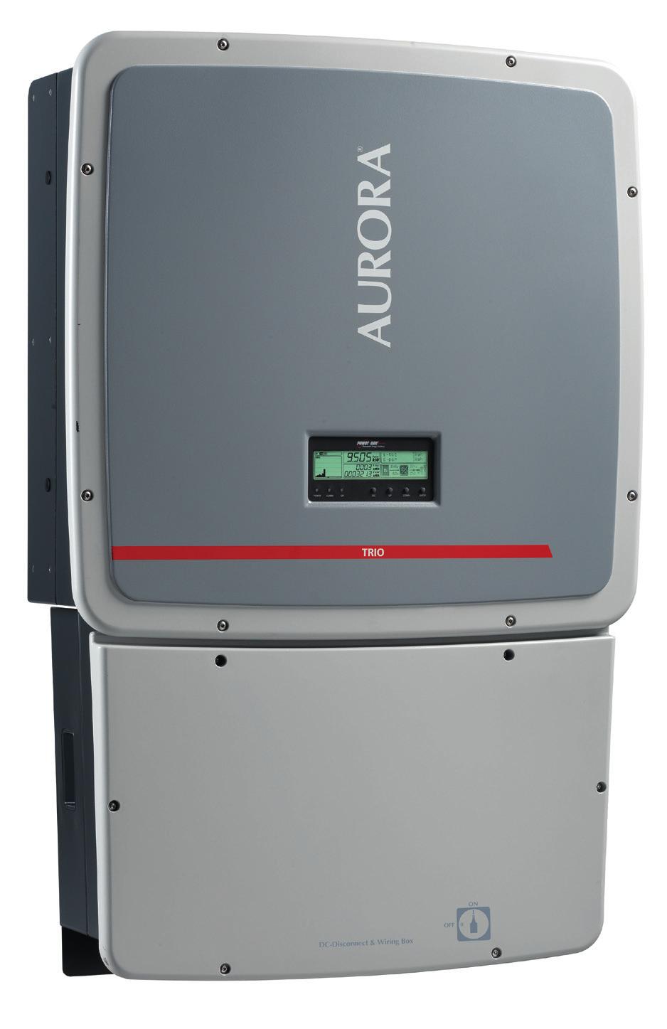
2 AURORA TRIO Photovoltaic Inverters TRIO-20.0/27.6-TL US Technical Manual
3 Page 2 of 114 Technical Manual: TRIO-20.0/27.6-TL US BCG.00627_AA Copyright 2013 Power-One Renewable Energy Solutions LLC. All rights reserved. No part of this document may be reproduced in any form or by any means without the prior written permission of Power-One Renewable Energy Solutions LLC. Power-One Renewable Energy Solutions LLC makes no representations, express or implied, with respect to this document or any of the equipment and/or software it may describe; including (without limitation) any implied warranties of utility, or merchantability for any particular purpose. All such warranties are expressly disclaimed. Power- One Renewable Energy Solutions LLC, its subsidiaries, affiliates, distributors and dealers shall not be liable for any indirect, special, incidental, or consequential damages under any circumstances. Power-One Renewable Energy Solutions LLC reserves the right to make changes to this document without notice and shall not be responsible for any damages, including indirect, special, incidental or consequential damages, caused by reliance on the content presented, including, but not limited to, any omissions, typographical errors, arithmetical errors or listing errors. All trademarks, logos, trade names, service marks and copyrighted materials used in this document are the property of their respective owners. Failure to designate a mark as registered does not mean that such mark is not a registered trademark. The Power-One name and logo are registered trademarks of Power- One, Inc. in the U.S.A. and other countries. All rights reserved. No licenses are conveyed herein, implicitly or otherwise, under any intellectual property rights. Power-One Renewable Energy Solutions LLC 740 Calle Plano Camarillo, California, United States
4 Page 3 of 114 Technical Manual: TRIO-20.0/27.6-TL US BCG.00627_AA Contents PART 1 INTRODUCTION & SAFETY INTRODUCTION SAFETY... 7 PART 2 UNPACK AND SELECT INSTALLATION LOCATION GENERAL CONDITIONS SELECT THE INSTALLATION LOCATION PART 3 MOUNTING AND WIRING AVAILABLE VERSIONS GRAPHICAL REPRESENTATION OF TRIO WALL MOUNTING WIRING DETAILS SETTING THE COUNTRY STANDARD AND LANGUAGE PART 4 OPERATION GUIDE GENERAL CONDITIONS MONITORING AND DATA TRANSMISSION DISPLAY AND KEYPAD COMMISSIONING DESCRIPTION OF THE MENUS PART 5 TROUBLESHOOTING GUIDE GENERAL CONDITIONS ALARM MESSAGES AND DISPLAY CODES THE POWER 0NE SERVICE CALL PART 6 MAINTENANCE GUIDE GENERAL CONDITIONS ROUTINE MAINTENANCE OTHER MAINTENANCE CR2032 BATTERY REPLACEMENT STORAGE AND DISMANTLING PART 7 APPENDIX TECHNICAL DATA FIELD ADJUSTABLE TRIP LIMITS FOR VOLTAGE AND FREQUENCY MPPT CONFIGURATION EXAMPLES ENVIRONMENTAL SENSORS PROTECTIVE DEVICES WITHIN THE AURORA INVERTER STRINGS AND ARRAYS FCC REMARKS INDEX OF TABLES AND FIGURES
5 Page 4 of 114 Technical Manual: TRIO-20.0/27.6-TL US BCG.00627_AA PART 1 INTRODUCTION & SAFETY
6 Page 5 of 114 Technical Manual: TRIO-20.0/27.6-TL US BCG.00627_AA Part 1 Introduction and Safety 1.1 INTRODUCTION SAVE THESE INSTRUCTIONS. This manual contains important instructions for models indicated on the front cover that shall be followed during installation and maintenance of the inverter PURPOSE The purpose of this document is to support the qualified technician, who has received training and/or has demonstrated skills and knowledge in construction, in installing and maintaining this Power-One AURORA TRIO Photovoltaic (PV) Inverter. This manual does not cover any details concerning equipment connected to the inverter such as the solar modules. Information concerning the connected equipment is available from the respective manufacturer INSTALLATION The installation is to be done by a qualified installer, normally a licensed electrician or contractor, according to the applicable local code regulations (National Electric Code (NEC), Canadian Electric Code (CEC), and other) MAINTENANCE AND SERVICE Maintenance and service procedures must comply with the manufacturer's documentation. For more detailed information, see Maintenance, Part 6. Call Power-One Customer Service at for a list of qualified service contractors FIGURES AND IMAGES IN THIS MANUAL The photos in this manual may differ slightly from the final model shipped and the color of the components may not match those illustrated; however the information is still applicable.

7 Page 6 of 114 Technical Manual: TRIO-20.0/27.6-TL US BCG.00627_AA Part 1 Introduction and Safety STORAGE OF THIS INFORMATION Keep this document in a safe place near the AURORA TRIO Inverter for easy access during installation and maintenance. It must be accessible for approved service and maintenance personnel at any time ADDITIONAL INFORMATION More information on Power-One s AURORA TRIO Inverter can be found at
8 Page 7 of 114 Technical Manual: TRIO-20.0/27.6-TL US BCG.00627_AA Part 1 Introduction and Safety 1.2 SAFETY IMPORTANT SAFETY INSTRUCTIONS! SAVE THESE INSTRUCTIONS KEEP IN A SAFE PLACE! WARNINGS IN THIS DOCUMENT This is a list of special safety symbols used in this manual that highlight potential safety risks and/or useful information. The symbol usage is described below: Symbol DANGER: WARNING: CAUTION: WARNING Usage Indicates a hazardous situation that can result in deadly electric shock hazards, other serious physical injury, and/or fire hazards. Indicates directions which must be fully understood and followed in their entirety in order to avoid potential safety hazards including equipment damage or personal injury. The reader should stop, use caution and fully understand the operations explained before proceeding. DANGEROUS VOLTAGE The product works with high voltages. All work on the AURORA Inverter must follow the described documentation and must comply with all prevailing codes and regulations associated with high voltages. WARNING HOT TEMPERATURE Some surfaces may become hot; do not touch the product while it is in operation. UL1741 Standard for Safety for Inverters, Converters, Controllers and Interconnection System Equipment for use with Distributed Energy Resources. CSA-C22.2 No General Use Power Supplies. THE INSTALLER MUST READ THIS DOCUMENT IN ITS ENTIRETY BEFORE INSTALLING OR COMMISSIONING THIS EQUIPMENT.
9 Page 8 of 114 Technical Manual: TRIO-20.0/27.6-TL US BCG.00627_AA Part 1 Introduction and Safety Equipment Safety Warnings In addition to the safety and hazard symbols, the following symbols are also used in this installation guide: System earth conductor (main grounding protective earth, PE) Alternating Current (AC) Value ø Direct Current (DC) Value Phase Grounding (earth) The equipment has various labels. Those with a yellow background refer to safety concerns. Be sure to read all labels before beginning installation of the equipment. If any questions arise as to the meaning or intent of these notices, please contact Power-One Technical Support at General Installation Warnings The AURORA TRIO Transformerless Inverter is designed and tested according to international safety requirements (UL1741/IEEE1547); however, certain safety precautions must be observed when installing and operating this inverter. Read and follow all instructions, cautions and warnings in this installation manual. WARNING: All operations regarding transport, installation and start up, including maintenance, must be carried out by qualified, trained personnel and in compliance with all prevailing local codes and regulations.
10 Page 9 of 114 Technical Manual: TRIO-20.0/27.6-TL US BCG.00627_AA Part 1 Introduction and Safety Assembly Warnings Prior to installation, inspect the unit to ensure absence of any transport or handling damage, which could affect insulation integrity or safety clearances; failure to do so could result in safety hazards. Assemble the inverter per the instructions in this manual. Use care when choosing installation location and adhere to specified cooling requirements. Unauthorized removal of necessary protection features, improper use, incorrect installation and operation may lead to serious safety and shock hazards and/or equipment damage Electrical Connection Warnings This grid-tied inverter system operates only when properly connected to the AC utility grid. Before connecting the services of the AURORA grid-tied inverter to the AC utility grid, contact the local power distribution company to receive the appropriate approvals. This connection must be made only by qualified technical personnel. Wiring methods used should be in accordance with the National Electric Code, ANSI/NFPA 70 and/or any prevailing local codes and regulations. WARNING: CAUTION: Systems with inverters typically require external disconnect switches or protective devices (e.g., fusing circuit breakers) depending upon the local safety regulations. Output circuits must be isolated from the enclosure and system grounding, required by Sections and of the National Electric Code, ANSI/NFPA 70, and is the responsibility of the installer. The Aurora Inverter should be connected only to a dedicated branch circuit. For models that do not include AC output overcurrent protection, it is the responsibility of the end user to provide protection for the AC output circuit. To reduce the risk of fire, connect Auxiliary Input only to a circuit provided with 25 amperes maximum branch circuit overcurrent protection in accordance with the National Electrical Code, ANSI/NFPA 70.
11 Page 10 of 114 Technical Manual: TRIO-20.0/27.6-TL US BCG.00627_AA Part 1 Introduction and Safety APPROPRIATE USAGE The AURORA Inverter is a photovoltaic inverter that converts direct current of a PV array into alternating current and feeds that power into the AC utility grid. This AURORA Inverter is designed for outdoor use, but can be used indoors if installed to specified environmental and mounting parameters stated in this manual, and abiding by the National Electric Code. (See Environmental Conditions in section below and General Installation Conditions in section for more information.) WARNING: If installed indoors, the inverter must be inaccessible to unqualified persons. Figure 1-1: PV array structure in Independent configuration
12 Page 11 of 114 Technical Manual: TRIO-20.0/27.6-TL US BCG.00627_AA Part 1 Introduction and Safety Figure 1-2: PV array structure in Parallel configuration CAUTION: Power-One accepts no liability for damage of any kind that may arise from incorrect or careless operation. The equipment must not be used in ways that do not fall within the intended field of use.
13 Page 12 of 114 Technical Manual: TRIO-20.0/27.6-TL US BCG.00627_AA Part 1 Introduction and Safety Conditions of Use CAUTION: The inverter can be used only with photovoltaic modules that do not require one of the poles to be grounded. The operating current dispersed during the normal operation MUST NOT exceed the limits documented in the technical specifications. Only one photovoltaic source can be connected to the input of the inverter (do not connect batteries or other sources of power supply). The inverter can be connected to the utility grid in qualified countries only. The inverter can only be used if all the technical requirements in this manual are observed and applied Environmental Conditions Adverse or constrained environmental conditions can lead to a reduction in performance. The equipment can be installed outdoors, but only in environmental conditions that do not prevent operation. Care must be taken to provide adequate ventilation if installed indoors Improper or Prohibited Use The following actions are dangerous and strictly forbidden under the terms of the warranty: Installing the equipment in environments with flammable conditions. Using the equipment with safety devices not working or disabled. Using the equipment or parts of the equipment by connecting it to other machines or equipment, unless otherwise expressed. Modifying areas that are operator restricted and/or altering parts of the equipment in order to vary the performance or change its protection. Cleaning with corrosive products that may corrode parts of the equipment or generate electrostatic charges. Using or installing the equipment or parts of it without having read and correctly interpreted the contents of this manual. Warming or drying rags on unit or accessory parts is dangerous and could compromise the ventilation and cooling of the components.
14 Page 13 of 114 Technical Manual: TRIO-20.0/27.6-TL US BCG.00627_AA Part 1 Introduction and Safety SAFETY INSTRUCTIONS Warning These servicing instructions are for use by qualified personnel only. To reduce the risk of electric shock, do not perform any servicing other than that specified in the operating instructions. Danger - Be sure all flammable materials including construction items are away from the unit. Do not install the inverter in or near potentially explosive areas. Warning The AURORA TRIO is not provided with an isolation transformer and is intended to be installed per NFPA 70, with an ungrounded PV array. These models have no grounded input conductors. Do not connect an AURORA Inverter to the AC utility grid until receipt of a letter of authorization from the authority having jurisdiction. Install the AURORA Inverter in accordance with the electrical standards prescribed by the applicable National Electric Code (NEC), Canadian Electric Code (CEC), and/or by other local codes and regulations General Information The equipment has been manufactured in accordance with the strictest accident-prevention regulations and supplied with safety devices suitable for the protection of components and operators. Inform Power-One about non-standard installation conditions. Maintenance operations must be carried out according to the Maintenance section in Part 6 of this manual. It is essential to provide operators with correct information. They must read and comply with the technical information given in the manual and any other attached documentation. The instructions given in the manual do not replace the safety devices and technical data for installation and operation mounted on the product. They do not replace the safety regulations enforced in the country of installation and common sense rules. Do not use the equipment if any operating anomalies are found. Avoid temporary repairs.
15 Page 14 of 114 Technical Manual: TRIO-20.0/27.6-TL US BCG.00627_AA Part 1 Introduction and Safety All repairs should be carried out using only qualified spare parts, which must be installed in accordance with their intended use and by a licensed contractor or authorized Power-One Service representative. Liabilities arising from commercial components are delegated to their respective manufacturers Thermal Hazard Warning - Certain parts may be extremely hot immediately following shut down due to normal elevated surface temperatures (e.g. transformers, capacitors, coils etc.). Prior to touching any part of the inverter use care to ensure surfaces and equipment are at touchsafe temperatures and voltages before proceeding. The customer and/or installer must appropriately instruct the operators or anyone who may come near the equipment, and highlight, if necessary with notices or other means, the hazardous areas or operations: magnetic fields, hazardous voltages, high temperatures, possibility of discharges, generic hazard, etc. Anytime the inverter has been disconnected from the AC utility grid, use extreme caution as some components can retain charge sufficient to create a shock hazard. To minimize occurrence of such conditions, comply with all corresponding safety symbols and markings present on the unit and in this manual Clothing and Protective Devices Appropriate Personal Protective Equipment (PPE) must be worn at all times when operating or servicing this equipment. All operations on the equipment should be performed with properly electrically insulated instruments.
16 Page 15 of 114 Technical Manual: TRIO-20.0/27.6-TL US BCG.00627_AA Part 1 Introduction and Safety Location of Safety Notices and Labels Please note the location of safety notices on the AURORA Inverter for notification and protection. They are located on both side panels of this unit. Labels are not to be hidden with external objects or parts such as rags, boxes, or other such equipment. They should be cleaned periodically and always maintained in view CONDITIONS OF WARRANTY Warranty conditions are described in a certificate supplied with the equipment. The warranty is understood to be valid if the user observes what is described in this manual. Any conditions deviating from those described must be explicitly agreed upon in writing. After inspecting the TRIO Inverter, fill out the warranty information and submit it to Power-One. Submitting this information will register the unit with the manufacturer and the owner will receive technical updates. Warranty exclusions can be found on the Power-One Renewable Energy website in the download section of the AURORA TRIO product page.
17 Page 16 of 114 Technical Manual: TRIO-20.0/27.6-TL US BCG.00627_AA PART 2 UNPACK AND SELECT INSTALLATION LOCATION
18 Page 17 of 114 The Manual: TRIO-20.0/27.6-TL US BCG.00627_AA Part 2 Unpack and Select Installation Location 2.1 GENERAL CONDITIONS Some specifications are not applicable to small equipment or components TRANSPORTATION AND HANDLING Transportation of the equipment, especially by road, must be carried out by suitable ways and means for protecting the components (in particular, the electronic components) from violent shocks, humidity, vibration, etc. During handling, do not make any sudden or fast movements that can create dangerous swinging. WARNING During transportation the TRIO equipment should only be stacked three high. For storage purposes, it can withstand a maximum load of four pieces of equipment (stacked five high), if stored correctly. DO NOT stack with equipment or products other than those indicated LIFTING Power-One packages and protects individual components using suitable means to make their transport and subsequent handling easier. Due to the weight and complexity of this equipment, Power-One recommends the process of loading and unloading of this equipment be done by an experienced or specialized staff knowledgeable in material handling. Where indicated or where there is a provision, eyebolts or handles can be inserted and used as lifting points. Do not lift several units or parts of the equipment at the same time, unless otherwise indicated UNPACKING AND CHECKING Discard packaging elements immediately to avoid injury. When opening the package, check that the equipment is undamaged and confirm all components are present. If you find any defects or damage, stop unpacking and consult the carrier, and also promptly inform Power-One.


19 Page 18 of 114 The Manual: TRIO-20.0/27.6-TL US BCG.00627_AA Part 2 Unpack and Select Installation Location INCOMING INSPECTION It is the customer s responsibility to examine the condition of the unit. Upon receipt of Power-One s AURORA grid-tied inverter, please check the following: Inspect the shipping container for any external damage. Inventory the contents against Table 2-1 below and verify receipt of all items. Use care not to discard any equipment, parts, or manuals. Call the delivering carrier if damage or shortage is detected. If inspection reveals damage to the inverter, contact the supplier, or authorized distributor for a repair/return determination and instructions regarding the process. Table 2-1: Components shipped with equipment COMPONENTS FOR ALL MODELS QTY Mounting bracket (1), wall anchor, screw, washer (10 each) 1 kit 8 pin connector 4 3 pin connector 2 Torx wrench; 90 ; T20; 64x23mm 1 COMPONENTS FOR -S MODELS ONLY Jumpers for configuration of parallel input channels COMPONENTS FOR S1, -S1A, -S1B MODELS ONLY Jumper cables for configuration of parallel input channels OPTIONAL COMPONENTS AVAILABLE FROM POWER-ONE Optional lifting kit includes handles and eyebolts for lifting the inverter QTY 2 QTY 1 Red 1 Black QTY 1 kit

20 Page 19 of 114 The Manual: TRIO-20.0/27.6-TL US BCG.00627_AA Part 2 Unpack and Select Installation Location HANDLING THE TRIO The AURORA TRIO Inverter unit and wiring box arrive unattached and are installed separately to ease installation. When mounting the TRIO, it is recommended to install the wiring box first and complete all necessary wiring and conduit connections before mounting and attaching the inverter unit. INVERTER UNIT Weight: TRIO-20.0: 132 lbs/60 kg TRIO-27.6: 143 lbs/65 kg Number of lifting points : 4 The inverter portion weighs 132 pounds or more, depending on the version, and should be lifted by two persons. An optional lifting kit, with handles and eyebolts for lifting the inverter, is available from Power- One and can be used to assist in hanging the inverter on the mounting bracket. OPTIONAL LIFTING KIT M 12 mounting kit with handles and eyebolts The wiring box weight is listed below: COMBINER BOX UNIT Weight: -S version: 19 lbs/9 kg -S1, -S1A, -S1B: 25 lbs/11 kg
21 Page 20 of 114 The Manual: TRIO-20.0/27.6-TL US BCG.00627_AA Part 2 Unpack and Select Installation Location 2.2 SELECT THE INSTALLATION LOCATION GENERAL INSTALLATION CONDITIONS The installation must be done by qualified installers and/or licensed electricians according to the applicable local code regulations (National Electric Code, Canadian Electric code, and other). WARNING The installation must be carried out with the equipment disconnected from the grid (power disconnect switch open) and with the photovoltaic panels shaded or isolated Environmental Check See Technical Data in Appendix, Part 7 to check the environmental parameters to be observed (degree of protection, temperature, humidity, altitude, etc.). Do not install inverter where it could be exposed to direct sunlight to avoid unwanted power reduction due to an increase in the internal temperature of the inverter. Do not install in small closed rooms where air cannot circulate freely. Due to acoustical noise (about 50dBA at 1 m) from the inverter, do not install in rooms where people live or where the prolonged presence of people or animals is expected. To avoid overheating, always make sure the flow of air around the inverter is not blocked. Do not install in places where gases or flammable substances may be present.


22 Page 21 of 114 The Manual: TRIO-20.0/27.6-TL US BCG.00627_AA Part 2 Unpack and Select Installation Location INSTALLATION POSITION YES NO - direct YES NO - air flow YES sunlight restricted NO - heavy snow accumulation Figure 2-1: Outdoor installation examples When choosing the place of installation, comply with the following conditions: Install on a wall or strong structure suitable for bearing the weight. Install vertically with a maximum incline of +/- 5. If the inverter is tilted greater than the maximum incline, heat dissipation can be inhibited, resulting in automatic power reduction. Install in safe place where all switch handles and controls remain easy to reach. Install at eye level so the display and status LEDs can be seen easily. Maintain clearance distances to allow for normal control and maintenance operations. (Covers will need to be removed to carry out maintenance of the hardware and software of the inverter.) Figure 2-2: Wall positioning


23 Page 22 of 114 The Manual: TRIO-20.0/27.6-TL US BCG.00627_AA Part 2 Unpack and Select Installation Location For multiple-inverter installations, position the inverters side-by-side. Maintain minimum clearances between inverters. Individual clearances cannot overlap. If the space available does not allow the side-by-side arrangement, position the inverters in a staggered arrangement as shown in the figure below so that heat dissipation does not affect other inverters. Figure 2-3: Staggered installation arrangement For staggered or side-by side arrangements; make sure to add the minimum distances between inverters where applicable, as illustrated in Figure 2-4. Figure 2-4: Installation of multiple inverters with additive clearances
24 Page 23 of 114 Technical Manual: TRIO-20.0/27.6-TL US BCG.00627_AA PART 3 MOUNTING AND WIRING
25 Page 24 of 114 The Manual: TRIO-20.0/27.6-TL US BCG.00627_AA Part 3 Mounting And Wiring 3.1 AVAILABLE VERSIONS The inverters can be divided into two groups according to their rated output power of 20.0 kw or 27.6 kw. For inverters of equal output power, the differences between models are the configuration of the wiring box. A description of the four wiring box versions can be found in Table 3-1 below kw MODELS TRIO-20.0-TL-OUTD-S-US-480 TRIO-20.0-TL-OUTD-S1-US-480 TRIO-20.0-TL-OUTD-S1A-US-480 TRIO-20.0-TL-OUTD-S1B-US-480 Dimensions (HxWxD): 41.7 x 27.6 x 11.5 in 1061 x 702 x 292 mm Weight: 157 lbs./71kg 27.6 kw MODELS TRIO-27.6-TL-OUTD-S-US-480 TRIO-27.6-TL-OUTD-S1-US-480 TRIO-27.6-TL-OUTD-S1A-US-480 TRIO-27.6-TL-OUTD-S1B-US-480 Dimensions (HxWxD): 41.7 x 27.6 x 11.5 in 1061 x 702 x 292 mm Weight: 168 lbs/76kg Table 3-1: Wiring box configurations available TRIO-20/27.6-TL-OUTD-S-US-480 TRIO-20/27.6-TL-OUTD-S1-US-480 TRIO-20/27.6-TL-OUTD-S1A-US-480 TRIO-20/27.6-TL-OUTD-S1B-US-480 DC Disconnect Switch DC Disconnect Switch DC Fuses Class II DC Surge Protection DC Disconnect Switch DC Fuses Class II DC Surge Protection Class II AC Surge Protection DC Disconnect Switch DC Fuses Class II DC Surge Protection AC Fused Disconnect Switch

26 Page 25 of 114 The Manual: TRIO-20.0/27.6-TL US BCG.00627_AA Part 3 Mounting And Wiring NAMEPLATE The nameplate shown below is affixed to the inverter and provides the following information: 1. Product origin 2. Model name 3. DC input data 4. AC output data 5. Certification Made in Italy Figure 3-1: Sample nameplate for TRIO-20.0-TL-OUTD-S1-US-480 Technical data in this manual does not, however, supersede the data on the labels affixed to the equipment.
 07 Connector screws 08")
27 Page 26 of 114 The Manual: TRIO-20.0/27.6-TL US BCG.00627_AA Part 3 Mounting And Wiring 3.2 GRAPHICAL REPRESENTATION OF TRIO Ref. Description 01 Mounting bracket 02 Wiring box 03 Inverter 04 Coupling connector cover 05 Clamp screw 06 Handles (optional, see Wall Mounting section below for information) 07 Connector screws 08 Wiring box front cover Figure 3-2: Graphical representation of TRIO parts with references

28 Page 27 of 114 The Manual: TRIO-20.0/27.6-TL US BCG.00627_AA Part 3 Mounting And Wiring 3.3 WALL MOUNTING Included in the shipping package is a mounting kit with screws and wall plugs provided for mounting the metal bracket to a concrete wall. Position the wall bracket 01 perfectly level on the wall and use it as a drilling template. Drill the holes required using a drill with 10mm bit. Attach the bracket to the wall with the ten wall anchors, 10mm in diameter, (supplied in mounting kit). Hook the wiring box 02 on the bracket by inserting the heads of the rear screws in the slots in the bracket. It is not necessary to install the inverter unit 03 at this stage. Power-One recommends making the wiring box connections before attaching and mounting the inverter unit. Ensure that the DC disconnect switch handle is in the OFF position (see ). Remove the front cover of the wiring box 08 and follow the wiring details in section 3.4 below to complete the necessary connections. Upon completion of the wiring, loosen the connector screws 07 to remove the coupling connector cover 04 that protects the connector between the wiring box and the inverter unit. (These screws will then be used to attach the wiring box to the inverter unit.) Store the cover in the special pocket provided at the rear of the wiring box 04.
 Hook the inverter unit 03 to the bracket by inserting the head of the rear screws in the slots as shown in the figure.")

29 Page 28 of 114 The Manual: TRIO-20.0/27.6-TL US BCG.00627_AA Part 3 Mounting And Wiring Figure 3-3: Wall mounting example Attach and mount the inverter unit. (Do not replace the wiring box front cover until the inverter unit is attached.) Hook the inverter unit 03 to the bracket by inserting the head of the rear screws in the slots as shown in the figure. To make lifting easier, an optional lifting kit is available from Power-One containing handles and eyebolts that can be attached to holes in the side of the inverter unit. Working from the bottom of the wiring box, connect the two parts by tightening the clamp screw 05 using 20mm size socket. 05 The clamp screw 05 is accessed from the bottom of the wiring box and used to secure the wiring box to the inverter unit. 05 Once the wiring box and inverter unit are connected, tighten the two connector screws 07 with at least 13.3 ft-lbs (18Nm) torque using a 13mm size socket. The screws are located inside the top of the wiring box. Replace the front cover of the wiring box 08 with at least 18 in-lbs (2Nm) torque to ensure proper waterproof sealing
30 Page 29 of 114 The Manual: TRIO-20.0/27.6-TL US BCG.00627_AA Part 3 Mounting And Wiring 3.4 WIRING DETAILS PREPARING TO CONNECT THE GRID-TIED PV INVERTER It is the responsibility of the installer to provide external disconnect switches and Overcurrent Protection Devices (OCPD) as required by National Electric Codes and other prevailing regulations. An automatic overcurrent device (e.g., circuit breaker) must be installed between the TRIO Inverter and the AC utility grid. The AURORA TRIO is not provided with an isolation transformer and is intended to be installed per NFPA 70, with an ungrounded PV array External AC disconnect switch To protect the AC connection line of the inverter, Power-One recommends the following characteristics when installing a device for protection against overcurrent: Type Voltage/Current rating TRIO-20.0-TL US TRIO-27.6-TL US Automatic circuit breaker with differential thermal magnetic protection 40A/600V 50A/600V Checking the correct polarity of the strings WARNING Verify that the DC voltage in the wiring box has the correct polarity and is within the operational range. Using a voltmeter, check that the voltage of each string has the correct polarity and at the coldest expected operating temperature, will fall within the input voltage limits accepted by the inverter (see Technical Data in Appendix, Part 7).
31 Page 30 of 114 The Manual: TRIO-20.0/27.6-TL US BCG.00627_AA Part 3 Mounting And Wiring Ground Fault Detection and Interruption Scheme As required by UL1741 CRD 2010, the Power-One AURORA TRIO inverter incorporates two separate methods for detecting a ground fault in the ungrounded PV array, described below: The first method of detecting a ground fault is conducted on a daily basis before connecting to the grid and is also conducted throughout the day. During this test, the inverter measures the insulation resistance of the PV array conductors compared to ground. If the insulation resistance measured by the inverter is less than pre-programmed threshold, the inverter will not connect to the grid, display an error on the LCD screen and illuminate a red LED on the front of the inverter. The second method of detecting a ground fault is done continuously while the inverter operates during the day. The inverter measures the differential current of the three-phase AC lines looking for any values that would indicate leakage of current to ground on the DC conductors. Measurement of the ground leakage current is carried out simultaneously by two independent and redundant processors. To comply with UL1741, 2010 CRD the inverter responds differently depending on the amount of leakage current detected. If the absolute threshold of 300 ma is detected for a period of 300 msec, the inverter will disconnect. In addition, there are another three levels of leakage current thresholds: > 30 ma/sec with duration of 300 msec, > 60 ma/sec with duration of 150 msec and > 150 ma/sec with duration of 40 msec. If either processor detects an unacceptable value for the respective period of time, the inverter will immediately disconnect from the grid, display an error on the LCD screen and illuminate a red LED on the front of the inverter. As a further safety precaution, in compliance with UL1741 CRD 2010, the inverter conducts an isolation monitor interrupter self-test before connecting to the grid or every 24 hours, whichever is sooner. This test validates that the circuitry needed to perform the isolation test operates normally and has not been damaged. All errors generated when a ground fault is detected are permitted to occur 4 times within a 24 hour period and any ground fault error requires a manual reset of the inverter by a trained technician. This is intended to ensure that equipment with a ground fault is not connected to the grid.
32 Page 31 of 114 The Manual: TRIO-20.0/27.6-TL US BCG.00627_AA Part 3 Mounting And Wiring WIRING BOX COMPONENTS There are four models of the wiring box available in either 20 kw or 27.6 kw versions. The major differences between the four wiring box layouts are shown below: TRIO-XX.X-TL-OUTD-S-US-480: DC Disconnect 14 TRIO-XX.X-TL-OUTD-S1-US-480: DC disconnect DC fuses (8 per MPPT) 22 Class II DC surge protection 15 TRIO-XX.X-TL-OUTD-S1A-US-480: DC disconnect DC fuses (8 per MPPT) 22 Class II DC surge protection 15 Class II AC surge protection 19
33 Page 32 of 114 The Manual: TRIO-20.0/27.6-TL US BCG.00627_AA Part 3 Mounting And Wiring TRIO-XX.X-TL-OUTD-S1B-US-480: DC disconnect DC fuses (8 per MPPT) 22 Class II DC surge protection 15 Fused AC Disconnect Switch 20 Table 3-2: Complete list of graphical reference numbers Ref. Description 01 Mounting bracket 02 Wiring box 03 Inverter 04 Coupling connector cover 05 Clamp screw 06 Optional lifting handles 07 Connector screws 08 Wiring box front cover 09 Communication card 10 Service openings 11 DC openings 12 Jumpers (-S version) 13 DC terminal block (-S version) 14 DC disconnect switch handle 15 Class II DC surge protection (-S1, -S1A, -S1B versions) 16 AC cable openings 17 AC terminal block 18 AC board (-S, -S1 versions and S1B version*) *S1B version located between fused disconnect switch and enclosure 19 Class II AC surge protection (-S1A version) 20 Fused AC disconnect switch (-S1B version) 21 Anti-condensation valve 22 DC fuse holders (-S1, -S1A, -S1B versions) 23 Display 24 Keypad 25 LED panel 26 Heatsink 27 Equipment ground conductor busbar 28 AC ground

34 Page 33 of 114 The Manual: TRIO-20.0/27.6-TL US BCG.00627_AA Part 3 Mounting And Wiring Conduit Entries and DC Disconnect Switch Handle Conduit entries for all versions are located on the bottom of the wiring box along with the DC disconnect switch handle 14. A silkscreen imprinted on the wiring box front cover 08 displays the ON/OFF positioning of the disconnect switch handle. In the OFF position (open and locked), the DC disconnect switch handle will be turned counter-clockwise in a position parallel to the wall. In the ON position, the DC disconnect switch handle must be pushed in and turned clockwise in a position perpendicular to the wall. A locking tab prevents the wiring box cover from being removed when the switch is in the ON position. The cover is only removable with the DC disconnect switch handle set to the OFF position. The conduit entries and DC disconnect switch handle are illustrated below. Make sure the appropriate conduit hub is employed for the use specified in order to maintain required spacing between wiring groups and ensure the integrity of the NEMA 4X environmental rating. Ref. Description 10 Service cable opening with plastic threaded plug Trade size 1/2 11 DC cable openings with plastic threaded plug * Trade size 1, 1 ½ 14 DC disconnect switch 16 AC cable opening with plastic threaded plug Trade size 1 21 Anti-condensation valve * If a 2 conduit is needed for DC cable, the DC cable entries can be punched to accommodate these using a knockout hole punch. Figure 3-4: Conduit entries and DC switch bottom view The DC switch (14) disconnects the photovoltaic panel current from the inverter when the switch is in OFF position. It DOES NOT disconnect the AC connection to the grid.
 control.")

35 Page 34 of 114 The Manual: TRIO-20.0/27.6-TL US BCG.00627_AA Part 3 Mounting And Wiring INDEPENDENT OR PARALLEL CONFIGURATION OF DUAL INPUTS The AURORA TRIO Inverters have dual inputs with independent maximum power point tracking (MPPT) control. Each of the input inverters is dedicated to a separate array with independent maximum power point tracking (MPPT) control. This means that the two arrays can be installed with different positions and orientation. Each array is controlled by an MPPT control circuit. When operated in the dual input mode, the inverter can optimize two independent arrays. The two trackers can be configured in parallel to handle power and/or current levels higher than those a single tracker can handle Double MPPT configuration Independent mode The double MPPT structure allows the management of two photovoltaic arrays that are independent of each other (one for each input channel). The arrays can differ from each other in installation conditions, type and number of photovoltaic modules connected in series Single MPPT configuration Parallel mode Strings of photovoltaic modules having the same type and number of panels in series can be connected to each single channel; they must also have the same installation conditions (in terms of orientation to the SOUTH and inclination from the horizontal plane).

36 Page 35 of 114 The Manual: TRIO-20.0/27.6-TL US BCG.00627_AA Part 3 Mounting And Wiring Refer to Table 7-5 in the Appendix for guidelines regarding the choice of Parallel or Independent configurations. The TRIO Inverter is set in independent mode by default. The following sections describes how to connect the inverter in parallel mode. In order to operate in parallel mode from a single array, it is necessary to connect the inputs in parallel using jumpers or jumper cables (both provided with this inverter). The a01 switch located on the communication card 09 must also be set to parallel mode as described below Switch a01 on Communication Card The switch a01 located on the communication card (09) is used to select the input configuration. The TRIO is shipped in the default configuration of IND (independent) mode with the a01 switch toggled to the right. Move the switch to the left to select PAR (parallel) mode.


37 Page 36 of 114 The Manual: TRIO-20.0/27.6-TL US BCG.00627_AA Part 3 Mounting And Wiring S VERSION ONLY Parallel Configuration The switch a01 situated on the communication card 09 must be set to PAR. The DC terminal blocks 13 must be connected by means of a solid copper jumper 12, (provided with this inverter), to parallel the MPPTs. Install jumpers between the two channels (positive and negative) and tighten in place with at least 22 in-lbs (6Nm) torque to ensure proper waterproof sealing. Connect these two terminal blocks with a jumper to parallel the POSITIVE MPPTs. POS NEG Connect these two terminal blocks with a jumper to parallel the NEGATIVE MPPTs.

38 Page 37 of 114 The Manual: TRIO-20.0/27.6-TL US BCG.00627_AA Part 3 Mounting And Wiring S1, -S1A, -S1B VERSIONS ONLY Parallel configuration The switch a01 situated on the communication card 09 must be set to PAR. Included in the TRIO packaging are two jumper cables, one red and one black. The red wire connects the positive terminals of MPPT 1 and 2 and the black wire connects the negative terminals of MPPT 1 and 2. A removable transparent cover protects access to live parts on the upper DC side of the wiring box. In order to connect the wires, remove the four screws in place on the removable cover. Connect the wires by plugging into the feeder terminals in the positions shown below. Tighten the screw on top of each feeder terminal to 50 in-lbs (6 Nm) torque and pull on the wire to confirm it is secure. Replace the removable cover when complete.
39 Page 38 of 114 The Manual: TRIO-20.0/27.6-TL US BCG.00627_AA Part 3 Mounting And Wiring CONNECTION TO THE PV FIELD (DC SIDE) The electrical installation of the Aurora inverter must be performed in accordance with the electrical standards prescribed by the local regulations and by the National Electric Code. Refer to the Canadian Electrical Code, CEC Table 2 and Table 4 (for Canada) or National Electrical Code, NFPA Table (for US), for suitable wire size (AWG). Use wire rated for 75 C or 90ºC (167 F or 194 F) and Copper Wire Only. The connections can be made with the wiring box 02 detached from the inverter 03 (which will be mounted and connected later for commissioning). When working with the wiring box 02 detached, pay particular attention in outdoor installations, where the coupling connector must always be protected by installing the coupling connector cover 04 on its housing. The DC disconnect switch (14) disconnects the DC current from the photovoltaic panels when the switch is open in the OFF position. It DOES NOT disconnect the AC connection to the grid. To disconnect the inverter from the AC grid, an AC switch must be disconnected. WARNING The S1B version is the only model that includes an integrated AC disconnect switch in the wiring box. To prevent electrocution hazards, all the connection operations must be carried out with the DC disconnect switch (14) turned to OFF position and locked out.
40 Page 39 of 114 The Manual: TRIO-20.0/27.6-TL US BCG.00627_AA Part 3 Mounting And Wiring Connection of DC inputs on the -S model For the -S model, DC input connections are made by passing the cables through the DC cable openings 11 and connecting them to the DC terminal block 13. The acceptable wire size ranges from 12 AWG to 2 AWG. Tighten with at least 22 in-lbs (6Nm) torque. Remove the threaded plastic plug and nut from the DC cable opening 11 and replace with the appropriately sized conduit hub (see section ). Insert the cable through the conduit opening and connect the cable to the correct terminal on the DC terminal block 13. Once the connection to the DC terminal block 13 is made successfully, tighten the conduit hub with at least 44 in-lbs (5Nm) torque in order to create a seal to maintain the integrity of the NEMA 4X rating. Figure 3-5: TRIO version S wiring box
41 Page 40 of 114 The Manual: TRIO-20.0/27.6-TL US BCG.00627_AA Part 3 Mounting And Wiring Connection of DC inputs on the -S1, S1A, and -S1B models only For these models, DC input connections are made by passing the cables through the DC cable openings 11 and connecting them to the DC fuse holders 22. The acceptable wire size ranges from 18 AWG to 6 AWG; refer to local code for appropriate wire size. Fuse holders have screw terminals and torque depends on wire size (see Appendix, section.7.1.1). Tighten to at least 30 in lbs (3.4 Nm) torque. Remove the plastic threaded plug and nut from the DC cable opening 11 and replace with the appropriately sized conduit hub (see section ). Insert the cable through the conduit opening and connect the cable to the correct input channel (if using the parallel configuration, either input channel is acceptable) on the DC fuse holder 22. Refer to Section for configuration of dual inputs. Once the connection to the DC fuse holder 22 is made successfully, tighten the conduit hub with at least 44 in-lbs (5Nm) torque in order to create a seal to maintain the integrity of the NEMA 4X rating. Figure 3-6: TRIO Version -S1 wiring box

42 Page 41 of 114 The Manual: TRIO-20.0/27.6-TL US BCG.00627_AA Part 3 Mounting And Wiring Figure 3-7: TRIO Version -S1A wiring box Figure 3-8: TRIO Version -S1B wiring box
43 Page 42 of 114 The Manual: TRIO-20.0/27.6-TL US BCG.00627_AA Part 3 Mounting And Wiring STRING PROTECTION - S1, -S1A, AND S1B MODELS ONLY These TRIO wiring box versions come with 15A, 1000V DC rated fuses installed. To determine the correct fuse to use with your PV array, refer to the National Electrical Code and or your local electrical code GRID OUTPUT CONNECTION (AC SIDE) Wiring methods used should be in accordance with the National Electric Code, ANSI/NFPA 70 and/or any prevailing local codes and regulations. When connecting the inverter to the grid, either a wye connection (three phase lines and a neutral line) or a delta connection (three phase lines) can be used. In either above connection type, the ground wire connection is mandatory. The cable used can be a 5-pole wire (for wye connections) or a 4-pole wire (for delta connections). This cable must pass through the AC cable opening 16 to make the connections to the AC terminal block 17 When working with the Wiring Box (02) detached, ensure that the Coupling Connector Cover (04) is installed to protect the Coupling Connector, especially when detached outdoors.


44 Page 43 of 114 The Manual: TRIO-20.0/27.6-TL US BCG.00627_AA Part 3 Mounting And Wiring Characteristics and Sizing of the Line Cable The wire size of the AC line conductor must be sized in order to prevent unwanted disconnections of the inverter from the grid due to high impedance of the line that connects the inverter to the power supply point. If the impedance is too high, it causes an increase in the AC voltage that, in compliance with UL1741 and IEEE1547, causes the inverter to switch off. To avoid an increase in the AC voltage level, which may lead to nuisance faults, size the conductor for a drop of less than 1% Wire Installation The TRIO Inverter has pressure type terminal blocks for connection of the AC conductors. To connect wiring to these blocks use the following procedure: Strip ½ of insulation from the end of the conductor to be terminated. Use a small (~1/4 wide) flat blade screwdriver to open the pressure contact: Insert the screwdriver in the rectangular tool slot. Lightly press the screwdriver toward the wire slot until the clamp opens; hold the clamp open with the screwdriver. Insert the conductor into the socket until seated. Release the pressure on the screwdriver and remove it from the slot. Check security of wire in the connector by tugging on the wire.

45 Page 44 of 114 The Manual: TRIO-20.0/27.6-TL US BCG.00627_AA Part 3 Mounting And Wiring Connection to the AC Terminal Block To prevent electrocution hazards, all the connection operations must be carried out with the external AC disconnect switch downstream of the inverter (grid side) open and locked out. Before connecting the inverter to the grid, the grid standard for your country must be properly set. Refer to Section 3.5 for instructions on how to configure this setting. For all models, connection to the AC terminal block 17 is made by inserting the cables through the AC cable opening 16. Use Copper wire only, AWG #8-4 / 75 C or AWG# 6-4 / 90 C for TRIO 27.6 kw models Use Copperwire only, AWG #6-4 / 75 C or AWG# 6-4 / 90 C for TRIO 20.0 kw models Remove the threaded plastic plug from the AC cable opening 16 and replace with the appropriately sized conduit hub (see section ). Insert the cable through the conduit opening and connect the conductors (Neutral, L1, L2, L3, and Ground for wye connections or L1, L2, L3, and Ground for delta connections) to the corresponding terminals on the AC terminal block 17. Confirm that the L1, L2, and L3 line connections have not been swapped with the Neutral connection.
 Table 3-3: Communication card description with graphical references Ref.")
46 Page 45 of 114 The Manual: TRIO-20.0/27.6-TL US BCG.00627_AA Part 3 Mounting And Wiring CHARACTERISTICS THE COMMUNICATION CARD A removable plastic cover prevents access to the section of the wiring box where the communication card resides. In order to access this area, remove the four screws in place on the cover. Figure 3-9: Communication card (09) Table 3-3: Communication card description with graphical references Ref. Description a01 Switch for setting parallel-connected or independent input channels a02 Rotary switches for setting the country and the language of the display a03 Switch for setting analog sensor 1 to Volts or ma * a04 Switch for setting analog sensor 2 to Volts or ma * a05 Connection to the multi-function relay a06 Connection of environmental sensors: AN1, AN2, PT100, PT1000 * a07 Connection for the RS-485 PC line (SERVICE), RS-485 PMU line (MODBUS), of the auxiliary 5V and the remote ON/OFF
 a09 Switch for setting the termination resistance of the RS-485 PC line (SERVICE) a10 Connection for the")
47 Page 46 of 114 The Manual: TRIO-20.0/27.6-TL US BCG.00627_AA Part 3 Mounting And Wiring Ref. Description a08 Switch for setting the termination resistance of the RS-485 PMU line (MODBUS) a09 Switch for setting the termination resistance of the RS-485 PC line (SERVICE) a10 Connection for the RS-485 PC line on RJ45 connector (SERVICE) a11 RS-485 PC communication card housing (SERVICE) a12 Connection for of the RS-485 PMU line on RJ45 connector (MODBUS) a13 RS-485 PMU communication card housing (MODBUS) a14 Switch for setting the inverter in normal or service mode a15 Inverter data memory card housing a16 CR2032 battery housing * * See Appendix, section 7.4 for more information Connections to the communication card Each cable connected to the communication card 09 must go through one of the two ½ openings 10. Remove the threaded plastic plugs from the service cable opening 10 and replace with the appropriately sized conduit hub (see section ). The sensor cables are connected on the communication card 09 using the mating connectors supplied with the inverter. The cables for connecting the RS-485 (MODBUS/PMU) line can use the terminal connector a07 and the RJ45 connector a10, a12, to be connected to the dedicated port a10 or a12. The two RJ45 connectors a10, a12, available for RS-485 (MODBUS/PMU) communication are interchangeable. Either can be used for the end or for the restart of the line in making a daisy chain connection of the inverters. Connections made using the terminal connector a07 can also use the two RJ45 connectors interchangeably.
.")
48 Page 47 of 114 The Manual: TRIO-20.0/27.6-TL US BCG.00627_AA Part 3 Mounting And Wiring Serial communication (RS-485) There are two RS-485 communication lines on the inverter: SERVICE/PC - dedicated line for the connection of Power-One monitoring and service equipment. MODBUS/PMU - dedicated line for MODBUS RTU communications. Two different types of connections can be made for each line: 1. Connection of the conductors using terminal block a07 (+T/R, -T/R and GND). 2. Connection via RJ45 connectors connected to ports a10 or a12 crimped according to the following arrangement: Pin N⁰ Function 1 not used 2 not used 3 +T/R 4 not used 5 -T/R 6 not used 7 GND 8 not used Use a metal connector to provide cable shield continuity! Use an RS-485 data wire with one twisted pair, one ground conductor, and a shield with drain wire (Belden#3106A or equivalent). Signal Symbol Pair Cable Positive data +T/R A 1 Negative data -T/R A 2 Reference RTN B 1+2 Shield continuity must be provided along the communication line using the SH terminal (a07) and must be grounded at a single point.

49 Page 48 of 114 The Manual: TRIO-20.0/27.6-TL US BCG.00627_AA Part 3 Mounting And Wiring Daisy Chain units for connection to a monitoring system The RS-485 terminal block connectors are used to connect a single AURORA Inverter or enable a multi-unit wiring configuration called daisy chain (pictured below). Using the appropriate cable, connect all the units according to the daisy chain cabling method ENTER-EXIT. Make sure to respect the correspondence between all signals. On the last inverter in a daisy chain, or on a single inverter, activate the termination resistance of the communication line by toggling switch a08 or a09 (to ON position) being careful to toggle the switch of the serial line used (SERVICE/PC or MODBUS/PMU). If a single inverter is connected to the monitoring system, activate the termination resistance of the communication line by toggling switch a08 or a09 (to ON position). The address on the inverter is set through the user interface on the display panel (see section 4.5 in Part 4: Operations). Set a different Modbus device ID on each inverter of the chain. No inverter should have Auto as its device ID. No more than 62 inverters can be connected to the same RS-485 line. It is recommended NOT to exceed a length of 3,300 ft/1000m for the communication line.

50 Page 49 of 114 The Manual: TRIO-20.0/27.6-TL US BCG.00627_AA Part 3 Mounting And Wiring Monitoring system via serial (RS-485) The RS-485 line can be connected for local monitoring from service/pc port with a PVI-USB-RS- 485_232 adapter and Aurora Communicator software. Equivalent RS-485 or RS232 adapters found on the market can also be used for the same purpose, however, they have not been specifically tested and Power-One cannot guarantee correct operation of the connection. Please note that these devices may also require external termination impedance, whereas this is not necessary with the Aurora PVI-USB-RS-485_232.
51 Page 50 of 114 The Manual: TRIO-20.0/27.6-TL US BCG.00627_AA Part 3 Mounting And Wiring Configurable relay The inverter has a multi-function relay a05, whose switching can be configured, for example, to activate a visual and/or audible alarm. The relay can be wired by the user as either normally open contact N/O or normally closed contact N/C. The devices to be connected to the relay can be of different types (light, sound, etc.) but must comply with the following requirements: Alternating current: Maximum Voltage: 240 Vac, OV Category II Maximum Current: 1 A Direct current: Maximum Voltage: 30 Vdc Maximum Current: 0.8 A Cable requirements: External diameter: from #4 - #8AWG Conductor size: from #25 - #15AWG N/C = Normally closed C = Common contact N/O = Normally open This contact can be used in four different operating modes that can be set in the menu of the inverter display (see section in Part 4: Operations). The four operating modes and switch configurations are described below.
52 Page 51 of 114 The Manual: TRIO-20.0/27.6-TL US BCG.00627_AA Part 3 Mounting And Wiring Operating modes: Production - the relay switches whenever a connection to the grid occurs. If the N/O (or N/C) contact is chosen, the contact will stay open (or closed) until the inverter is connected to the grid. Once the inverter connects to the grid and starts to export power, the relay switches state and closes (or opens). When the inverter disconnects from the grid, the relay contact returns to its position of rest, namely open (or closed). Alarm - the relay switches whenever there is an alarm on the inverter (Error). No switching occurs when there is a Warning. If the N/O (or N/C) contact is chosen, the contact will stay open (or closed) until the inverter reports an error; once the inverter reports an error, the relay switches state and closes (or opens). The contact remains switched from its rest condition until normal operation is restored. Alarm (configurable): the relay switches whenever there is an alarm (Error) or a Warning, which has been previously selected by the user through the dedicated menu. If the N/O (or N/C) contact is chosen, the contact will stay open (or closed) until the inverter reports an error or a warning out of those selected from the menu. Once the inverter displays an error or a warning out of those selected, the relay switches state and closes (or opens) the contact. The relay remains switched from its rest condition until the alarm or warning has disappeared. Crepuscular (twilight): the relay usually switches when the voltage from the photovoltaic array exceeds/falls below the threshold set for grid connection. If the N/O (or N/C) contact is chosen, the contact will stay open (or closed) until the inverter has an input voltage higher than the one selected for grid connection. The contact remains switched from its rest condition for as long as the inverter is switched on (even if not connected to the grid). This mode is can be used to for disconnect large output transformers that could have unnecessary consumption during the night.
.")
53 Page 52 of 114 The Manual: TRIO-20.0/27.6-TL US BCG.00627_AA Part 3 Mounting And Wiring Remote control The connection and disconnection of the inverter to and from the grid can be controlled externally. The function must be enabled in the menu on the inverter display (see section in Part 4: Operations). If the remote control function is disabled, the switching on of the inverter is dictated by the presence of the normal parameters that allow the inverter to connect to the grid. If the remote control function is operating, the switching on of the inverter also depends on the state of the R ON/OFF terminal compared to the GND terminal present on the connector a07 of the communication card 09. When the R ON/OFF signal is brought to the same potential as the GND signal (i.e. by making a short circuit between the two terminals of the connector), the inverter disconnects from the grid. The remote control OFF condition is shown on the display. The connections of this control are made between the R ON/OFF input and GND. Since this is a digital input, there are no requirements to be observed as regards wire size (it only needs to comply with the sizing requirement for passing cables through the cable openings and the terminal connector).

54 Page 53 of 114 The Manual: TRIO-20.0/27.6-TL US BCG.00627_AA Part 3 Mounting And Wiring 3.5 SETTING THE COUNTRY STANDARD AND LANGUAGE There are different grid parameters according to the country in which the inverter is installed. The language of the display menus will be also be defined by the grid standard chosen. Before turning the rotary switches, make sure the inverter is switched off! The TRIO is shipped with the predefined settings for the North American market, positions 0/4. If it is necessary to change the maximum output power settings, the inverter can be configured to position 1/A using the two rotary dials a02. (See output settings below.) Country Settings TRIO-20.0-TL US TRIO-27.6-TL US Default Maximum Output Power (0/4) Maximum Output Power (1/A) This is done using a small flat head screwdriver and moving the dial of the first switch to line up with position 1 on the rotary dial a02, and the second switch to line up with position A. (If a switch position not assigned to a grid standard is selected, Invalid Selection appears.) Saving the country standard and language The settings become permanent after 24 hours of operation of the inverter (it does not need to be connected to the grid, and only needs to be powered). The time remaining before the settings become fixed can be seen in the dedicated menu, and a notice appears if the time has expired. If it is necessary to change the standard of the country after the settings have been fixed (after 24 hours of operation) please contact Power-One s technical support department with the part number and serial number of the inverter.
55 Page 54 of 114 Technical Manual: TRIO-20.0/27.6-TL US BCG.00627_AA PART 4 OPERATION GUIDE
56 Page 55 of 114 The Manual: TRIO-20.0/27.6-TL US BCG.00627_AA Part 4 Operation Guide 4.1 GENERAL CONDITIONS One of the first rules for preventing damage to the equipment and injury to the operator is to have a thorough knowledge of the user interface operations. Power-One cannot be held responsible for damage to the equipment or the operator if caused by incompetence, insufficient qualifications or lack of training. 4.2 MONITORING AND DATA TRANSMISSION As a rule, the inverter operates automatically and does not require manual intervention. When there is not enough solar radiation to supply power for export to the grid, (e.g. during the night) it disconnects automatically and goes into stand-by mode. The operating cycle is automatically restored when there is sufficient solar radiation. At this point, the lights on the LED panel 25 will indicate this state USER INTERFACE The inverter is able to provide information about its operation through the following: Warning lights (LEDs) LCD for displaying operating data Data transmission via Modbus RTU TYPES OF DATA AVAILABLE The inverter provides two types of data, which are usable through the Modbus RTU and/or through the display 23. Real-time operating data Real-time operating data can be transmitted on request through the communication lines and are not recorded in the inverter. For data transmission to a computer, the free software supplied with the inverter can be used (please check at for more updated versions). Internally stored data The inverter internally stores a set of data that are necessary for processing statistical data and an error log with time stamps.
57 Page 56 of 114 The Manual: TRIO-20.0/27.6-TL US BCG.00627_AA Part 4 Operation Guide 4.3 DISPLAY AND KEYPAD Description of the Keypad There are three LED indicators on the left side of the keypad 24 and four buttons on the right. A description of the LED conditions can be found in Table 4-1 below. The buttons are used to review data on the display 23, (see section for description of symbols and display fields), and access the data logged internally on the AURORA TRIO using menus (described in section 4.5 below). 23 POWER ALARM GFI ESC UP DOWN ENTER Figure 4-1: Function of buttons and LEDs LED Green POWER LED Yellow ALARM LED Red GFI LED ESC button UP button DOWN button ENTER button Table 4-1: Description of LED status Description Indicates that the inverter is working correctly. This LED flashes while the grid is being checked when the unit is commissioned. If a valid grid voltage is measured, the LED stays on continuously, provided there is sufficient sunlight to activate the unit. If not, the LED continues to flash until there is sufficient sunlight for activation. During this phase, the LCD display shows the Waiting for sun. message. Indicates that the inverter has detected an anomaly. The type of problem is shown on the display. The GFI (ground fault indicator) LED indicates that the inverter has detected a ground fault on the DC side of the photovoltaic array. When this fault is detected, the inverter immediately disconnects from the grid and the relevant error warning appears on the LCD. This button allows you to exit a mode or go back. This allows you to read the data on the display by scrolling upwards, or to increase the set value to modify it during data entry. This allows you to read the data on the display by scrolling downwards, or to decrease the set value to modify it during data entry. This allows you to confirm the operation or to enter the set data item.
58 Page 57 of 114 The Manual: TRIO-20.0/27.6-TL US BCG.00627_AA Part 4 Operation Guide LED INDICATORS In their various combinations, the LEDs can indicate conditions that are different from the single one. The following table shows the possible combinations of activation of the LEDs in relation to the operating state of the inverter. These can be viewed on the LED panel 25. Warning and Error messages are described in Troubleshooting, Part 5 Table 4-2: LED indicators Key: LED on LED flashing LED off Any of the above conditions Status of the LEDs Operating State Description : green: 2: yellow: 3: red: 1: green: 2: yellow: 3: red: 1: green: 2: yellow: 3: red: 1: green: 2: yellow: 3: red: 1: green: 2: yellow: 3: red: 1: green: 2: yellow: 3: red: 1: green: 2: yellow: 3: red: 1: green: 2: yellow: 3: red: AURORA self-disconnects during night COMMUNICATION ERROR: Loss of communication within the inverter STAND-BY: Inverter power-up initialization STAND-BY WITH WARNING: inverter initialization in presence of a fault or anomaly. Grid is disconnected. RUN: The inverter is connected to and feeding energy to the grid. RUN with WARNING: The inverter is connecting and feeding power to the grid in the presence of an anomaly. INVERTER ALARM GRID ALARM: There is a problem with the electrical grid. Input voltage less than 90 Vdc at both inputs There is a loss of communication between the inverter circuitry and the display or to the communication and control cards. Transition state during which the inverter is waiting for sufficient sunlight to start. The inverter checks the parameters necessary for connection to the grid, such as input voltage, grid voltage, etc. The inverter is waiting for sufficient sunlight to start exporting energy to the grid and checks the parameters necessary for connection to the grid. However it has also detected a condition which could limit its functionality. A warning message (Wxxx code) is on the LCD. Normal operation. The inverter automatically searches for and tracks the maximum power point (MPPT) from the PV array. The inverter is connected to the grid and an anomaly, which may be internal or external to the inverter, has been detected, turning on the yellow LED. A warning message (Wxxx) is on the LCD. A malfunction of the inverter prevents export of power to the grid. An error message (Exxx) is displayed on the LCD. The grid voltage is not within the standards of the country of installation, so the inverter is unable to export energy to the grid. An error message (Exxx) is displayed on the LCD.

59 Page 58 of 114 The Manual: TRIO-20.0/27.6-TL US BCG.00627_AA Part 4 Operation Guide Description of Symbols and Display Fields The operating parameters of the equipment can be viewed on the display 23 and include warnings, alarms, channels, voltages, etc. During operation, the display cycles through the various operating parameters. See Table 4-3 below for a description of the display fields. Figure 4-2: Numerical reference of display fields
60 Page 59 of 114 The Manual: TRIO-20.0/27.6-TL US BCG.00627_AA Part 4 Operation Guide Table 4-3: Display fields and symbols Num. Symbol Function Description b1 Tx-R Indicates the transmission and reception of data through the RS-485 line. b2 RS-485 Indicates the RS-485/Modbus communication line is active. b3 Warning Indicates the potential power reduction due to the input voltage and/or due to a setting via MODBUS/PMU by the grid company. b4 b5 Temperature derating Instantaneous power value Indicates that the inverter is power limiting due to high internal temperature. Displays the instantaneous power that the inverter is feeding into the grid. b6 MPPT scan Indicates that the MPPT scan function has been enabled through the menu. b7 Graphic Display Displays the inverter parameters in rotation and displays the error codes (if present). It is used for moving through the menu. b8 Power graph Displays the power of the inverter (from 0 to 100%) over 8/16/24 hours; this parameter can be set. b9 Total Energy Value Displays the total energy produced since installation of the inverter. b10 Daily energy value Displays the energy produced over a day. b11 Photovoltaic power source Indicates that the PV field voltage is higher than the Vstart of the inverter. The number represents themppt string or channel (in the case of channels in parallel, 1 is always displayed). b12 DC voltage value Displays the voltage from the input channel of the photovoltaic array. b13 DC current value Displays the current from the input channel of the photovoltaic array. b14 DC/DC circuit Indicates the DC/DC input circuit.
61 Page 60 of 114 The Manual: TRIO-20.0/27.6-TL US BCG.00627_AA Part 4 Operation Guide Num. Symbol Function Description b15 DC/AC circuit Indicates the circuit for conversion from DC to AC. b16 AC voltage value Displays the reading of the grid voltage (VAC). The number at the side indicates the phase. b17 AC current value AC current value is displayed. b18 Connection to the grid Displays the reading of the current or frequency that is fed into the grid. The number at the side indicates the phase 1, 2 or 3 of which the AC current value is displayed. These are displayed in sequence during connection to the grid. The icon depicts a plugged-in plug if connected to the grid, and an unplugged plug if disconnected from the grid. b19 Grid status This icon can indicate three AC voltage states: b20 Cyclic display activated/ deactivated Icon not present: no grid voltage Flashing icon: grid voltage present but outside the parameters set by the grid standard Icon present: grid voltage present and within the parameters set by the grid standard A padlock will be present if the data on the display b10 is locked. If the data is scrolling (cyclic) two arrows will be present.

62 Page 61 of 114 The Manual: TRIO-20.0/27.6-TL US BCG.00627_AA Part 4 Operation Guide 4.4 COMMISSIONING Power-One provides commissioning service (initial setup and power up). Please contact Power- One Customer Service at Do not place objects of any kind on the inverter during operation! Do not touch the heatsink while the inverter is operating! Some parts may be very hot and cause burns. The incoming voltage must not exceed the maximum values shown in the technical data in order to prevent damage to the equipment. Consult the technical data in the Appendix for further details. NOTE: Before proceeding with commissioning, make sure you have carried out all the checks and verifications indicated in the section on preliminary checks (section 3.4.1). The inverter commissioning procedure is as follows: 1. Put the DC disconnect switch handle 14 in ON position (see section for placement and use of disconnect switch). 2. Once the inverter is powered, icon b11 comes on to indicate that the voltage from the photovoltaic array has reached the Vstart threshold (voltage necessary for connecting the inverter to the grid). For input voltages lower than Vstart, the icon remains off, the Waiting for sun message is shown on the display and the voltage and current values are present (icons b12 and b13).
63 Page 62 of 114 The Manual: TRIO-20.0/27.6-TL US BCG.00627_AA Part 4 Operation Guide 3. If there are no irregularities due to the checking of the grid voltage and frequency parameters, the grid connection sequence starts. Once all the checks are finished, if all the grid parameters are complied with, icon b19 comes on. During these checks, the icon b19 is flashing. This check can take several minutes (from at least 30 seconds to no more than a few minutes), depending on grid conditions and grid standard settings. 4. At this point, icon b14 flashes to indicate the startup phase. This icon will stay on steady once the booster is operating in steady state (this icon will normally flash for only a few seconds). At the same time as icon b14 comes on (steady), icon b15 will come on to indicate that the inverter circuit has begun working (DC- AC). 5. Immediately after this, the procedure of connection to the grid will start, during which icon b18 will come on and the icons on the line will be displayed in sequence until the inverter is connected. After the inverter is connected, the icons on line b18 will come on steady. If the inverter disconnects from the grid, the icons of the left side (cable and plug separated) of the line b18 will stay on. 6. Once the connection sequence has been completed, the inverter starts to operate and indicates its correct operation by making a sound and by the green LED coming on steady on the LED panel 25. This means there is sufficient solar radiation to feed power into the grid. 7. If there is not sufficient solar power, the unit will repeat the procedure until all the parameters that allow connection to the grid (grid voltage and frequency, confirmation of no ground fault) are within the range. During this procedure, the green LED flashes.
64 Page 63 of 114 The Manual: TRIO-20.0/27.6-TL US BCG.00627_AA Part 4 Operation Guide OPERATIONAL BEHAVIOR OF THE DISPLAY If the MPPT scan function is enabled, icon b6 will be shown on the display. See the MPPT settings menu, section below. This icon will flash during scanning. During operation, the following values are displayed in rotation: Voltage and current (b12 and b13) from the PV field. Depending on the MPPT configuration, the voltages and currents of one or both channels will be displayed. The input channel considered is indicated by the value entered on icon b11. Voltage and current (b16 and b17) on the various phases. The voltages and currents of one (1) or three phases (1, 2, 3) will be displayed. The phase is shown on the right side of the voltage and current values. At the end of the display, the grid frequency will be indicated in field b17 and the line voltage will be indicated in field b16. At the same time, the primary readings made by the inverter will be displayed in rotation on the graphic display b7. If the icons b18 on the left side (cable and plug separated) stay on, it means the inverter is disconnected from the grid. If the icons display the plug connected, it means the grid is good for connection. Display of the Power Graph b8 The period of time is represented by the horizontal axis of the graph and can be set by the user to 8, 16 or 24 hours; broken into segments of 30, 60 or 120 minutes. The vertical axis represents the maximum power reduction (30 kw for the TRIO-27.6 and 22 kw for the TRIO-20.0) and corresponds to the outgoing exported power value. The power value expressed by each column of the graph represents the average value of the power during the period relating to the time unit.

65 Page 64 of 114 The Manual: TRIO-20.0/27.6-TL US BCG.00627_AA Part 4 Operation Guide BEHAVIOR OF THE LEDS Next to each state of the inverter, (indicated through the steady or intermittent lighting of the relevant LED), a message is shown on the display 23, in area b7. The message identifies the operation in progress or the detected fault/anomaly found. b In the event of malfunction, it is extremely dangerous to try to eliminate the fault personally. The instructions given below must be carefully followed; if you do not have the experience and necessary qualification to work safely, please contact a specialized technician Insulation fault LED What to do after insulation fault warning When the red LED comes on, try to reset the warning through the multi-function button ESC on the LED panel 25. If the inverter reconnects to the grid, the fault was due to temporary phenomena. Power-One advises a system inspection by the installer or a specialized technician if this malfunction occurs frequently. If the inverter does not reconnect to the grid, make the inverter safe by disconnecting it (by means of the disconnect switches) on the both the DC side and the AC side, and then contact the installer or an authorized service center to have the photovoltaic field fault repaired.
66 Page 65 of 114 The Manual: TRIO-20.0/27.6-TL US BCG.00627_AA Part 4 Operation Guide 4.5 DESCRIPTION OF THE MENUS The graphic display section b7 consists of 2 lines with 16 characters per line. When moving through the menu using the buttons of the LED panel 25, area b7 is used to: display the operating state of the inverter and the statistical data display the service messages for the operator display the alarm and fault messages for the operator change the settings of the inverter b USING THE PANEL BUTTONS The UP and DOWN buttons of the LED panel 25 are used to move around a menu or to increase/decrease the settable values. The ESC button allows access to the three main submenus, STATISTICS, SETTINGS and INFORMATION, and also can be used to return to the previous submenu while moving through the menus. The ENTER button allows access to the submenu choices while moving though the menus and allows the main menu scroll mode to be changed (icons b20 are activated): CYCLIC: Display cycles through the main parameters of the inverter. LOCKED: Display is locked on the screen. Use this option when you want to continuously monitor a condition.
67 Page 66 of 114 The Manual: TRIO-20.0/27.6-TL US BCG.00627_AA Part 4 Operation Guide STATISTICS MENU Selecting STATISTICS from the three main sub-menus gives access to: Lifetime - This section of the menu allows you to display the Total statistics for Lifetime operation: Time: Total operating time E-tot: Total energy produced Val. : Total production value, calculated with the currency and conversion coefficient set in the relevant section of the SETTINGS menu CO 2: Amount of CO 2 saved Partial - This section of the menu allows you to display the partial statistics since the counter was last reset (*see below): Time: Partial operating time since the counter was last reset E-par: Partial energy produced since the counter was last reset PPeak: Peak power value measured since the partial counter was activated Val. : Partial production value, calculated with the currency and conversion coefficient set in the relevant section of the SETTINGS CO2 : Amount of CO 2 saved daily since the counter was last reset * To reset all the counters of this submenu, press the ENTER button and hold for more than 3 seconds until you hear a beep. Today - This section of the menu allows you to display the daily statistics: E-day: Daily energy produced PPeak: daily peak power value Val. : Daily production value, calculated with the currency and conversion coefficient set in the relevant section of the SETTINGS Last 7 days - This section of the menu allows you to display the statistics for the last 7 days Last month - This section of the menu allows you to display the statistics for the last month Last 30 days - This section of the menu allows you to display the statistics for the last 30 days Last 365 days This section of the menu allows you to display the statistics for the last 365 days Select any one of the above time periods to view the following information: E-##: Energy produced over the period selected Val. : Economic gain over the period selected CO2: Amount of CO 2 saved for the period selected User period - This section of the menu allows the statistics for a period selected by the user to be displayed. Once the start and end dates for the user period has been selected, the following data is available: E: Energy produced during the selected period Val. : Value of production for the selected period, calculated with the currency and conversion coefficient set in the relevant section of the SETTINGS menu CO2 : Amount of CO 2 during the selected period
68 Page 67 of 114 The Manual: TRIO-20.0/27.6-TL US BCG.00627_AA Part 4 Operation Guide SETTINGS MENU When SETTINGS is selected from the three main submenus, the first screen for the password is populated in the display. The default password is This can be changed using the display buttons and the following procedure: Press ENTER to scroll the digits (from left to right) Press ESC to return to the previous digit (from right to left) Press ESC several times to return to the previous menus Press DOWN to progressively scroll the numerical scale downwards (from 9 to 0) Press UP to progressively scroll the numerical scale upwards (from 0 to9) After entering the password, press ENTER to access the information available in this section. Address - This section of the menu allows you to set the address for the serial communication of single inverters connected to the RS-485 line. The addresses that can be assigned are 2 to 63. Use the UP and DOWN buttons to scroll the numerical scale. At present, the AUTO selection cannot be used Display Settings - This section of the menu allows you to set the characteristics of the display: 1. Light: setting of the mode and adjustment of the brightness of the display Mode: ON: Light always on OFF: Light always off AUTO: Automatic light control. The light comes on whenever a button is pressed and stays on for 30 sec, after which it gradually goes out. Intensity: adjustment of display brightness (scale from 0 to 9) 2. Contrast: adjustment of display contrast (scale from 0 to 9) 3. Buzzer: button sound setting ON: the sound of the buttons is activated OFF: the sound of the buttons is deactivated 3. Power Graph: Time range: 8 H, 16 H, 24 H Service - This section of the menu is reserved for installers. To access this, it is necessary to have a dedicated password that can be provided by the Power-One Service. The following table describes the display headings and descriptions of the Service Menu.
69 Page 68 of 114 The Manual: TRIO-20.0/27.6-TL US BCG.00627_AA Part 4 Operation Guide Display Set U>> Set U<< Set F>> Set F<< Set U> Set U> (10 min) Set U< Set F> Set F< Set Uconn> Set Uconn< Set Fconn> Set Fconn< Set Time U>> Set Time U<< Set Time F>> Set Time F<< Set Time U> Set Time U< Set Time F> Set Time F< Set Time Conn 1 Set Time Conn 2 Disable U>> Disable U<< Disable F>> Disable F<< Disable U> Dis. U> (10 min) Disable U< Disable F> Disable F< U>(10 min) Der. Slow ramp OF Derating OF Der. Rest. T Reset country S Accept boards Table 4-4: Service submenu Description Max grid voltage. Grid overvoltage (OV) threshold (extended range). Min grid voltage. Grid undervoltage (UV) threshold (extended range). Max grid frequency. Grid over-frequency (OF) threshold (extended range). Min grid frequency. Grid under-frequency (UF) threshold (extended range). Max grid voltage. Grid overvoltage (OV) threshold. Overvoltage (OV) protection of the average grid voltage value. Min grid voltage. Grid undervoltage (UV) threshold. Max grid frequency. Grid over-frequency (OF) threshold. Min grid frequency. Grid under-frequency (UF) threshold. Max grid voltage for connection. Maximum voltage threshold for the grid connection. Min grid voltage for connection. Minimum voltage threshold for the grid connection. Max grid frequency for connection. Maximum frequency threshold for the grid connection. Min grid frequency for connection. Minimum frequency threshold for the grid connection. Grid overvoltage (OV) threshold (extended range) protection trip time. Grid undervoltage (UV) threshold (extended range) protection trip time. Grid over-frequency (OF) threshold (extended range) protection trip time. Grid under-frequency (UF) threshold (extended range) protection trip time. Grid overvoltage (OV) threshold protection trip time. Grid undervoltage (UV) threshold protection trip time. Grid over-frequency (OF) threshold protection trip time. Grid under-frequency (UF) threshold protection trip time. Grid checking time before connection after generic fault. Grid check interval before the connection or after a generic fault. Grid checking time before connection after grid fault. Grid check interval before the connection after a grid fault. Enable/disable Grid overvoltage (OV) threshold (extended range). Enable/disable Grid undervoltage (UV) threshold (extended range). Enable/disable Grid over-frequency (OF) threshold (extended range). Enable/disable Grid under-frequency (UF) threshold (extended range). Enable/disable Grid overvoltage (OV) threshold. Enable/disable the overvoltage (OV) protection of the average grid voltage value. Enable/disable Grid undervoltage (UV) threshold. Enable/disable Grid over-frequency (OF) threshold. Enable/disable Grid under-frequency (UF) threshold Enable/disable the U> (10Min) protection threshold. Enable/disable the gradual feeding of power after the grid connection. Enable/disable the power derating mode in the event of grid overfrequency Set time of restart for power derating in the event of grid over frequency Resetting the grid standard selection time
70 Page 69 of 114 The Manual: TRIO-20.0/27.6-TL US BCG.00627_AA Part 4 Operation Guide New PW - This section of the menu allows you to change the password for accessing the SETTINGS menu (default 0000). We ADVISE you to be very careful in memorizing the new password. If the Password is misplaced, it will not be possible to access the inverter because there is no Reset function (for security reasons). Cash - This section of the menu allows you to set the name of the currency and the value given to 1 kwh of energy produced. The correct setting of these parameters allows you to display the actual earning/saving given by the system. Name: the chosen value is set (default is USD). Val/KWh: indicates the cost/incentive of 1 KWh expressed in the chosen currency (default is 0.14). Time - Allows you to set the current date and time (daylight saving time not included). Language - Allows you to set the required menu language. Vstart - This section of the menu allows you to set the Vstart voltage (separately for both channels if they are configured in independent mode), to adapt it to the requirements of the system. Change the activation voltage only if necessary. A configuration program that can help to correctly size the photovoltaic system is available at stringtool.power-one.com. Alarm - This section of the menu allows you to set the switching of a relay contact (available as a normally open contact N/O, and also as a normally closed contact N/C). This contact can be used, for example, to activate a siren or a visual alarm, control the disconnect device of an external transformer, or control an external device. Maximum ratings of the alarm contact: 240Vac/1A and 30Vdc/0.8A. The switching of the relay can be set in 4 different modes: PRODUCTION: the relay switches when the inverter connects to the grid. ALARM: the relay switches when there is an alarm (code E). ALARM (conf.): the relay switches if there are alarms (code E) or warnings (code W) chosen by the user from a list (the list may also show choices that are not envisaged for the specific model). CREPUSCULAR: the relay switches only when it exceeds the input voltage set for connection to the grid.
71 Page 70 of 114 The Manual: TRIO-20.0/27.6-TL US BCG.00627_AA Part 4 Operation Guide Remote ON/OFF - This section of the menu allows you to enable/disable the connection /disconnection of the inverter to/from the grid through the relevant control signal (R ON/OFF). Disable: the connection/disconnection of the inverter to/from the grid is dictated by the input (voltage from the photovoltaic array) and output (grid voltage) parameters of the inverter. Enable: the connection/disconnection of the inverter to/from the grid is dictated by the state of the R ON/OFF signal compared to the GND signal as well as by the input (voltage from the photovoltaic array) and output (grid voltage) parameters of the inverter. UV Prot. T - This section of the menu allows you to set the time for which the inverter stays connected to the grid after the input voltage has dropped below the undervoltage limit (set at 70% of Vstart). Power-One sets the time at 60 sec. The user can set it from 1 to 3600 sec. Example: with the UV Prot.time set at 60 seconds, if the Vin drops below 70% of Vstart at 9:00, the inverter stays connected to the grid (taking power from it) until 9:01. MPPT - This section of the menu allows you to set the parameters of the maximum power point tracking (MPPT) function. This function is useful when there are shaded areas on the PV array that can create several maximum power points in the work curve. MPPT amplitude: the amplitude of the interference introduced in DC is chosen through the setting of this parameter to establish the optimal working point. There are three settings to choose from (LOW, MEDIUM, and HIGH). The default setting is MEDIUM. Multi-max scan: through the setting of this parameter, you can enable/ disable the scan, decide the frequency with which the scan is carried out and override it manually. a. Enable/Disable: Enables/Disables the scan for identifying the maximum power point of the system. b. Scan Interval: this allows you to set the interval of time between scans. It must be borne in mind that, the shorter the interval between scans, the greater will be the loss of production due to the fact that, during the scan, energy is transferred to the grid but not at the maximum power point. Each scan takes 2 seconds. SENSORS PT100 AND PT1000 (Can be directly connected to the corresponding analog input; the PT100/PT1000 inputs of the acquisition card do not require the configuration of gain and offset) PVI-AEC-T100-ADH: adhesive PT100 sensor for module temperature measurement. PVI-AEC-T100-BOX: PT100 sensor for ambient temperature measurement. PVI-AEC-T1000-BOX: PT1000 sensor for ambient temperature measurement.
72 Page 71 of 114 The Manual: TRIO-20.0/27.6-TL US BCG.00627_AA Part 4 Operation Guide Alarm - This section of the menu allows you to enter a customized message that is shown immediately after the specific error message has been displayed. Enable/Disable: Enables/Disables the display of customized messages Writing of Msg: you can create a customized message that can be written on two lines of 16 characters each. To write the message, use the UP/DOWN arrows to choose the character you wish to select and press ENTER to confirm. Reactive Power This section of the menu allows you to manage the reactive power. Power Reduction This section of the menu allows you to adjust active power curtailment. Analog Inputs - This section of the menu allows you to set the analog sensors connected at the input (AN1 and AN2) Set Gain: Allows you to set the gain of the sensor Set Offset: Allows you to set the offset of the sensor Set of m Unit: Allows you to set the unit of measure of the sensor INFORMATION MENU Part No. - Allows you to display the part number (pn). Serial No. - Allows you to display the serial number of the equipment and the work week (from 1 to 52) and year of manufacture. Firmware - Allows you to display the revision of the firmware installed in the equipment. Country selector - Allows you to display information regarding the grid standard set with the rotary selectors. Actual value: Displays the set grid standard. New value: If the position of the rotary switches is changed (a new grid standard is therefore selected) during operation, the new standard selected will be displayed but will be made effective only after the equipment has been switched off and then on again and only if the time remaining for carrying out this operation has not expired (24h of operation). Set new value: Allows you to confirm/set the new grid standard set in the New value section of the previous menu. When this function is used, there will be no correspondence between the standard selected on the display and the position of the rotary selectors. Residual time: Displays the time remaining in which it is still possible to set a new grid standard. When the time expires, Locked will be displayed, which indicates it is not possible to change the grid standard again.
73 Page 72 of 114 Technical Manual: TRIO-20.0/27.6-TL US BCG.00627_AA PART 5 TROUBLESHOOTING GUIDE


74 Page 73 of 114 The Manual: TRIO-20.0/27.6-TL US BCG.00627_AA Part 5 Troubleshooting 5.1 GENERAL CONDITIONS AURORA TRIO Inverters comply with the standards set for grid-tied operation, safety, and electromagnetic compatibility. Before the product is shipped various tests are carried out successfully to ensure functioning, protection devices, performance and durability. In case of any possible malfunction of the inverter, solve problems as follows: 1. Work under safe conditions. Check that the connections between the inverter, the photovoltaic field and AC utility grid have been made correctly as stated in Part 1 Introduction and Safety and Part 3 Mounting and Wiring. 2. Carefully observe which LED is flashing and read the signal appearing on the display. Try to identify the type of fault found by following the instructions given in the Table 5-1 below. 5.2 ALARM MESSAGES AND DISPLAY CODES The equipment is able to indicate errors/warnings on the display only if the input voltage is higher than the Vdc min voltage (POWER LED flashing or on; see Operations section 4.4.1). b The messages and their codes are indicated on the highlighted part b10 of the display 23 and described in the table below.
75 Page 74 of 114 The Manual: TRIO-20.0/27.6-TL US BCG.00627_AA Part 5 Troubleshooting Display Message Ground Fault Display Codes Table 5-1: Alarm messages and display codes Alarm Cause Solution Red LED Ground Fault The alarm is generated when a If possible, measure the insulation ground leakage current is detected resistance using a megohmmeter in the DC section of the system. positioned between the photovoltaic field The alarm is accompanied by the (positive terminal short-circuited to the lighting up of the red LED on the negative pole) and ground. front of the inverter. If the measured value is less than 1 Megohm, the photovoltaic array must be checked by a technician/ installer to identify and eliminate the problem. If the measured value is greater than 1 Megohm and the error warning continues to be present, contact Power- One Service. Degauss error --- Degaussing state fail Input OC E001 Input Overcurrent The alarm appears when the You must check whether the composition inverter input current exceeds the of the PV array allows an input current set overcurrent threshold. that exceeds the maximum threshold allowed by the inverter and that the configuration of the (independent or parallel) inputs is carried out correctly. If the configuration of the PV array and the setting of the input channels are suitable, contact Power-One Service Input OV E002 Input Overvoltage No Parameters E003 Internal Parameters Error This alarm is indicated when themeasure the input voltage in the inverter inverter input voltage (coming from with a voltmeter. the PV array) exceeds the operating If it is higher than the maximum voltage of threshold. The alarm is triggered the operating interval, the alarm is real before reaching the absolute and you must check the configuration of threshold beyond which the the PV array. inverter will be damaged. When the If it is lower than the maximum voltage of inverter input voltage exceeds the the operating interval, the alarm is caused Over Voltage threshold, the inverter by an internal malfunctioning and you will not start because of the must contact Power-One Service generation of the alarm. The main microcontroller is unablethis is an error inside the inverter that to correctly initialize the two DSPs. cannot be checked externally. If the This is usually due to problem persists (after switching the communication problems on the inverter off and then on again), contact internal bus of the inverter. Power-One Service.
76 Page 75 of 114 The Manual: TRIO-20.0/27.6-TL US BCG.00627_AA Part 5 Troubleshooting Display Message Display Codes Bulk OV E004 Bulk Overvoltage Comm.Error E005 Alarm Cause Solution Internal communication Error Output OC E006 Output Overcurrent The alarm is raised when the The alarm can be triggered by causes voltage at the terminals of the bulkexternal to the inverter an excessive capacitors exceeds the overvoltage inverter input voltage can be detected as a threshold. bulk overvoltage condition. In this case, it is advisable to check the inverter input voltage and, if this value is near the input OV threshold, re-examine the configuration of the photovoltaic array. The alarm can be triggered by causes internal to the inverter, and in this case, you must contact Power-One Service. The alarm occurs when there areerror inside the inverter that cannot be communication problems between checked externally. If the problem persists the control devices inside the (after switching the inverter off and then inverter. on again), contact Power-One Service. The alarm appears when the Error inside the inverter that cannot be inverter output current exceeds thechecked externally. If the problem persists output overcurrent threshold of the (after switching the inverter off and then inverter. on again), contact Power-One Service. IGBT Sat E007 IGBT Saturation The alarm appears when one of the Once the error appears, the inverter active devices of the inverter is in attempts to resume normal operation. If saturation state. the error occurs sporadically, it may be caused by a sharp transition of the grid voltage or the input voltage but is not attributable to inverter malfunctioning. If the error is associated with an internal fault, it will continue to appear, and you must contact Power-One Service. Internal error E009 Internal Error Error inside the inverter Error inside the inverter that cannot be checked externally. If the problem persists (after switching the inverter off and then on again), contact Power-One Service. Bulk Low E010 Low Bulk Voltage Ramp Fail E011 Bulk ramp timeout The alarm can be triggered byif the error warning appears sporadically, causes external to the inverter: a it can be attributed to causes external to low inverter input voltage (just the inverter (insufficient irradiance, and above the activation voltage) that is therefore little power available from the not accompanied by sufficient PV field). availability of power from the If the problem appears systematically even photovoltaic array (typical in conditions of high solar radiation and condition of periods of insufficientwith input voltage significantly higher irradiance). than the activation voltage, contact Power- One Service. Error inside the inverter regarding Error inside the inverter that cannot be the time for starting steady state checked externally. If the problem persists operation of the DC-DC circuit. (after switching the inverter off and then on again), contact Power-One Service. DcDc Fail E012 Booster module Error inside the inverter regarding Error inside the inverter that cannot be error revealed by the operation of the DC-DC circuit. Inverter checked externally. If the problem persists (after switching the inverter off and then on again), contact Power-One Service.
77 Page 76 of 114 The Manual: TRIO-20.0/27.6-TL US BCG.00627_AA Part 5 Troubleshooting Display Message Wrong Mode Display Codes E013 Alarm Cause Solution Wrong Input Mode (parallel instead of independent) The alarm is generated only when Make sure the setting of the a01 switch the inverter is configured with has been intentionally positioned on parallel inputs. In this particular "PAR" and that the jumpers have been configuration, the inverter carries inserted between the two input channels. out the input voltage check of each If the configuration of the inverter is of the two channels, and the alarm correct, check that the input strings have is raised if the two voltages differ by the same number of panels in series, of the more than 20Vdc. usual make and with the same inclination/orientation. If both the configuration of the inverter and the characteristics of the PV field comply with the specifications, contact Power-One Service. Over Temp. E014 Overtemperature External temperature above 60 C. Wait for the temperatures to return within This parameter also depends on the operating range and for the inverter to power that the inverter must supply cool down If the problem persists (once since the measurement of the the ambient temperature has returned temperatures is carried out within the range), contact Power-One internally and is affected by the heatservice. dissipated by the components of the Remember to wait for the time necessary inverter. to allow the inverter to cool down. Bulk Cap Fail E015 Bulk Capacitor Fail Error inside the inverter regarding Error inside the inverter that cannot be a problem in the bulk capacitors. checked externally. If the problem persists (after switching the inverter off and then on again), contact Power-One Service. Inverter Fail E016 Inverter module The alarm is generated when aerror inside the inverter that cannot be error revealed by problem is detected in the inverter checked externally. If the problem persists Booster circuit (DC/AC). (after switching the inverter off and then on again), contact Power-One Service. Start Timeout Ground Fault E017 E018 Inverter module Error inside the inverter regarding Error inside the inverter that cannot be start- up timeout the time for starting steady state checked externally. If the problem persists operation of the DC-AC circuit(after switching the inverter off and then (Inverter). on again), contact Power-One Service. Leakage current The alarm is generated during See Appendix, section regarding fail normal operation of the inverterground faults in PV panels. when ground leakage current is If the measured value is greater than 1 detected in the DC section of the Megohm and the error warning continues system. The alarm is accompanied to be present, contact Power-One Service. by the lighting up of the red LED on the front of the inverter. The alarm message may also be generated for AC leakage currents associated with the capacitive nature of the PV array compared to ground.
78 Page 77 of 114 The Manual: TRIO-20.0/27.6-TL US BCG.00627_AA Part 5 Troubleshooting Display Message Self-Test Error 3 Self-Test Error 1 Display Codes E019 E020 Alarm Cause Solution Leakage current Before connecting to the grid, the This is an error inside the inverter that sensor self- test inverter carries out an Autotest that cannot be checked externally. If the fail regards the leakage current sensor. problem persists (after switching the The test is carried out by forcing a inverter off and then on again), contact current of known value in the Power-One Service. By its nature, the leakage current sensor: the alarm appears only before connection to microprocessor compares the read the grid. value with the known value. The error is generated if the comparison between the read value and the known value during the test is not within the allowed tolerance. Boost relay self-befortest fail inverter carries out some internal cannot be checked externally. If the connecting to the grid, the This is an error inside the inverter that tests. One of these tests regards the problem persists (after switching the correct operation of the relay. The inverter off and then on again), contact test is carried out by forcing the Power-One Service. By its nature, the switching of the relay and checking alarm appears only before connection to its functionality. The error is the grid. generated if a problem is found with the operation of the relay. Self-Test Error 2 Self-Test Error 4 E021 E022 Inverter relay self-test fail Relay self- test timeout Before connecting to the grid, the This is an error inside the inverter that inverter carries out a test that cannot be checked externally. If the regards the operation of the problem persists (after switching the inverter relay. The test is carried inverter off and then on again), contact out by forcing the switching of the Power-One Service. By its nature, the relay and checking its functionality. alarm appears only before connection to The error is generated if a problem the grid. is found with the operation of the relay. Time taken to execute the AutotestError inside the inverter that cannot be carried out on the relays of the checked externally. If the problem persists DC_AC circuit (inverter) is too long. (after switching the inverter off and then This may indicate a problemon again), contact Power-One Service. associated with the aforesaid relays. DC inj error E023 Internal error Dc-Injection out of range The error is generated if the direct If the grid voltage is distorted, report this component of the current supplied anomaly to the grid company for the to the grid exceeds the threshold of resolution of the problem If there is an 0.5% of the rated operating current. inverter fault, contact Power-One Service. In any case, the inverter does not stop because of the E023 error, but tries to connect to the grid again. Sporadic repetition of the error is a sign of large grid distortions or sudden changes in irradiance, whereas systematic repetition of the error warning will be a sign of an inverter fault. E024 Internal Error Error inside the inverter. Error inside the inverter that cannot be checked externally. If the problem persists (after switching the inverter off and then on again), contact Power-One Service.
79 Page 78 of 114 The Manual: TRIO-20.0/27.6-TL US BCG.00627_AA Part 5 Troubleshooting Display Message Riso Low Display Codes Alarm Cause Solution E025 Low insulation (not resistance shown on the display) Before connecting to the grid, the See Appendix, section regarding inverter measures the insulation Ground faults in PV panels. resistance of the PV field compared to ground. If the insulation If the measured value is greater than 1 resistance measured by the inverter mega ohm and the error warning is less than 1 MOhm, the inverter continues to be present, contact Powerdoes not connect to the grid and One Service. shows the Riso Low error. The causes may be: (Dampness increases leakage and can - Damaged PV panel(s). therefore be the cause of a reduction in - Junction box(es) of the panels not insulation resistance). properly sealed, so allowing water and /or dampness seepage ; - Problems in the connections between panels (not perfectly connected); - Poor quality cable junctions; - Presence of unsuitable (trigger voltage lower than the characteristics of the PV array strings) or damaged overvoltage surge arresters outside the inverter in the DC section. - Presence of dampness inside the field panel, if there is one. Vref Error E026 Bad internal Wrong reading on measurement of Internal error that cannot be checked reference voltage the reference voltage inside the externally. If the problem persists (even equipment after switching the inverter off and then on again), contact Power-One Service. Error Meas V Error Meas F Error Meas Z E027 E028 E029 VGrid Measures Fault FGrid Measures Fault ZGrid Measures Fault Error in the internal measurement This is an error inside the inverter that of the grid voltage (imposed bycannot be checked externally. If the regulations) to have a measurement problem is persistent (even after redundancy (2 measurements onswitching the inverter off and then on the same parameter carried out by again), contact Power-One Service. two different circuits). Error in the internal measurement This is an error inside the inverter that of the grid frequency (imposed by cannot be checked externally. If the regulations) to have a measurement problem is persistent (even after redundancy (2 measurements onswitching the inverter off and then on the same parameter carried out by again), contact Power-One Service. two different circuits). Error in the internal measurement Error inside the inverter that cannot be of the insulation resistance of the checked externally. The error occurs if the PV array compared to ground internal measurement is carried out (imposed by regulations) to have a before connection to the grid) If the measurement redundancy (2problem is persistent (even after measurements on the same switching the inverter off and then on parameter carried out by two again), contact Power-One Service. different circuits).
80 Page 79 of 114 The Manual: TRIO-20.0/27.6-TL US BCG.00627_AA Part 5 Troubleshooting Display Message Error Meas Ileak Error Read V Display Codes E030 E031 Error Read I E032 UTH E033 Under Temperature Interlock fail Alarm Cause Solution ILeak Measures Fault Error in the internal measurement This is an error inside the inverter that (carried out when the inverter iscannot be checked externally. If the connected to the grid) of the problem is persistent (even after leakage current of the DC side (PVswitching the inverter off and then on array) compared to ground again), contact Power-One Service. (imposed by regulations) to have a measurement redundancy (2 measurements on the same parameter carried out by two different circuits). Wrong V Measurement of the internal voltage This is an error inside the inverter that Measure at the terminals of the output relay cannot be checked externally. If the out of range. There is too great a problem appears repeatedly, contact difference in voltage between the Power-One Service. input and the output of the output relay. Wrong I Measure Measurement of the output voltage This is an error inside the inverter that unbalance (carried out between the cannot be checked externally. If the three phases) out of range. problem appears repeatedly, contact Power-One Service. Temperature outside the inverter Wait for the temperatures to which the below inverter is exposed to return within -25 C operating range. If the problem persists, contact Power-One Service. You must remember to wait for the time necessary to allow the inverter to warm up. E034 IGBT not ready Error inside the inverter Error inside the inverter that cannot be checked externally. If the problem persists (after switching the inverter off and then on again), contact Power-One Service. Remote Off E035 Waiting remote (not ON shown on the display) Vout error Avg E036 The inverter has been switched off Switch on the inverter remotely. If the unit remotely (remote OFF) and remains does not switch on, disable the remote in waiting state for the signal that on/off function and switch the equipment will switch it on again (remote ON). off completely and then switch it on again. If the problem persists (after re-enabling the Remote ON/ OFF function from the display), contact Power-One Service. Average Vout out The average grid voltage value Check the grid voltage at the inverter of range (every 10 minutes) does not fallconnection point. If the grid voltage within the allowed ranges. The grid diverges from the range because of grid voltage at the point connected to conditions, ask the grid company to adjust the inverter is too high. This may be the grid voltage. If the grid company caused by grid impedance that is authorizes a change to the inverter too high. Towards the end of the parameters, arrange the new limits with timeout, the inverter limits the Power-One Service. power to check whether the grid voltage stabilizes within the normal parameters. If this does not happen, the inverter disconnects from the grid.
81 Page 80 of 114 The Manual: TRIO-20.0/27.6-TL US BCG.00627_AA Part 5 Troubleshooting Display Message Display Codes Riso Low E037 Low insulation resistance (amorphous mode only) Alarm Cause Solution This error can appear only if the Check for the presence and correct Amorphous mode is enabled. This contacting of the two terminals of the function is enabled only in inverters grounding resistor installed inside the equipped with grounding kit and is inverter. used to monitor the voltage at the If possible, measure the insulation ends of the grounding resistor. The resistance using a megohmmeter error appears when the voltage at positioned between the PV field (positive the ends of the resistor connected terminal short-circuited to the negative between ground and pole of the pole) and ground (as described in the photovoltaic array exceeds 30V foroperation chapter). more than 30 minutes or 120V forif the measured value is less than 1 mega more than one second. ohm, the photovoltaic array must be checked by a technician/ installer to identify and eliminate the problem. If the measured value is greater than 1 mega ohm and the error warning continues to be present, contact Power- One Service. Mid Bulk OV E038 Mid bulk OV Restart inverter then call Power-One. Sun Low W001 (Low input voltage during switch-on of the inverter) Input UV W002 (Low input voltage during switch-off) Grid Fail W003 Grid Fail (grid voltage parameters outside the limits) Insufficient irradiance. Wrong Check the inverter input voltage. configuration of the PV array or a If it does not exceed the Vstart, check that configuration at the limit as there is sufficient irradiance and that the regards the minimum input voltage composition of the system is correct. If it of the inverter. exceeds the Vstart, contact Power-One Service. Insufficient irradiance Wrong Check the inverter input voltage. configuration of the photovoltaic If it does not exceed the Vstart, check that array or a configuration at the there is sufficient irradiance and that the limit as regards the minimum inputcomposition of the system is correct. If it voltage of the inverter. exceeds the Vstart, contact Power-One Service. This error warning appears when, Check the grid voltage on the inverter. If during normal operation of the absent, check for the absence of grid inverter, the grid parameters fall voltage on the supply. If the voltage tends outside the limits set by the grid to rise (when the inverter is connected), it company. means there are high line or grid No grid voltage (after the warning, impedances. Check the grid voltage on the the inverter goes on "No Vac") supply as well; if it is high, it means there Unstable grid voltage (downwards is high grid impedance. In this case, ask the and upwards) Unstable grid grid company to adjust the grid voltage. If frequency the grid company authorizes a change to the inverter parameters, arrange the new limits with the Power-One Service. If the voltage at the supply point is much lower than that measured on the inverter, the line must be adjusted (invertercounter). If the grid voltage and frequency fall within the limits (even when the inverter is connected to the grid), contact Power-One Service. Table fail W009 Empty Wind Table NOT APLLICABLE (wind models only)
82 Page 81 of 114 The Manual: TRIO-20.0/27.6-TL US BCG.00627_AA Part 5 Troubleshooting Display Message Fan Fail Display Codes W010 (not shown on the display) Alarm Cause Solution Fan Fail This error appears when there is Error inside the inverter that cannot be malfunctioning of the fan(s) insideresolved with external operations. If the the inverter. In this condition, the alarm is persistently repeated, contact yellow LED on the front panel Power-One Service. flashes. (Alarm not shown on the display; there is only a flashing yellow LED) Bulk UV W011 Bulk Undervoltage Battery low W012 Low internal clock battery voltage Reading of the internal voltage on Warning will appear when grid is low or the bulk capacitors carried out inverter is not turned on or functioning when the inverter is connected to properly. the grid. Internal battery for maintenance ofreplace the battery with the inverter the date/time settings is discharged completely switched off (disconnect AC or damaged. side and DC side) and be sure to observe the correct polarity. Clk fail W013 Internal clock fail The alarm appears when the time This is an error inside the inverter that shown on the display differs bycannot be resolved with external more than 1 minute from the operations. If the alarm is persistently internal time of the repeated, contact Power-One Service. microprocessors and indicates clock Jbox fail W017 NA NA NA SPD DC protection open W018 SPD DC protection open Overvoltage surge arresters Look at the inspection window present on situated on the DC side are each surge arrester (DC side). If it is red, damaged. the surge arrester is damaged and the cartridge must be replaced. If the alarm status continues to be present even though all the surge arresters have a green inspection window, contact Power- One Service. SPD AC W019 protection open SPD AC protection open Overvoltage surge arresters Look at the inspection window present on situated on the DC side are each surge arrester (AC side). If it is red, damaged. the surge arrester is damaged and the cartridge must be replaced. If the alarm status continues to be present even though all the surge arresters have a green inspection window, contact Power- One Service.
83 Page 82 of 114 The Manual: TRIO-20.0/27.6-TL US BCG.00627_AA Part 5 Troubleshooting 5.3 THE POWER 0NE SERVICE CALL Call Power-One Technical Support at The following information, which can be found on the display of the inverter, is necessary to initiate a call with Technical Support: Model number Serial number Week of production State of LED: Status of light(s) Steady or flashing Error message or code Identify the System structure: Information on the Photovoltaic Field Brand and model of photovoltaic panels Maximum array voltage and current values Number of strings in the array Number of panels for each string Provide a description of the conditions: Can the fault be reproduced? If so, how? Is the fault cyclical in nature? If so, how often? Was the fault apparent at the time of installation? If so, has it worsened? Describe the atmospheric conditions at the time the fault appears/appeared.
84 Page 83 of 114 Technical Manual: TRIO-20.0/27.6-TL US BCG.00627_AA PART 6 MAINTENANCE GUIDE
85 Page 84 of 114 Technical Manual: TRIO-20.0/27.6-TL US BCG.00627_AA Part 6 Maintenance Guide 6.1 GENERAL CONDITIONS Checking and maintenance operations must be carried out by specialized staff assigned to perform this work. DO NOT allow the equipment to be used if problems of any kind are found. Maintenance operations must be carried out with the equipment disconnected from the grid, unless otherwise indicated. After shutdown, wait at least 10 minutes before removing guards or covers in order to allow devices inside the unit to cool and allow any electrostatic charges and parasitic voltages to be discharged. For cleaning, DO NOT use rags made of filamentary material or corrosive products that may corrode parts of the equipment or generate electrostatic charges. Avoid temporary repairs. All repairs should be carried out using only genuine spare parts. The maintenance technician is under an obligation to promptly report any anomalies. To maintain the correct working performance, Power-One recommends having the systems checked by your installer after about 5 years of activity. Always use the personal protective equipment provided by the employer and comply with the safety conditions in Part 1 of this manual. Power-One accepts no liability if the checking and maintenance cycles indicated in this manual and in the attached documentation are not complied with correctly, and also when maintenance is entrusted to unqualified staff.
86 Page 85 of 114 Technical Manual: TRIO-20.0/27.6-TL US BCG.00627_AA Part 6 Maintenance Guide 6.2 ROUTINE MAINTENANCE Routine maintenance operations can be carried out directly by the user or by the installer. Clean the equipment once a month; in particular, the lower grill on the wiring box 02 through which the air for cooling the heatsink 26 passes and the heatsink itself. If possible, use an extractor or suitable pipe cleaners. Clean the photovoltaic panels every six months, at the change of season or as necessary. The performance of the system depends on the condition of the PV panels. To clean, follow the specifications of the PV panel supplier. Every six months or in the event of malfunction, check that the environmental conditions have not changed drastically (exposure to weather conditions); also check that the inverter or PV panels have not been shaded or isolated by foreign bodies. Once a year or in the event of malfunction, check the tightness of the cable opening plugs 10 or 11, the fitting of the connectors and front cover 08. Seepages may result in dampness and consequent short circuits. 6.3 OTHER MAINTENANCE These maintenance operations can be carried out only by the installer or trained maintenance personnel. Every six months or in the event of anomalies, especially after violent weather conditions, check the DC overvoltage surge arresters 15 (error W019) and the AC overvoltage surge arresters 18 (error W018). Both surge arresters are class II. Also check the fuses and replace the damaged ones. Before starting the inverter again, the cause of the fault must be resolved. Every six months or in the event of malfunctioning, check the tightness of all the connections, especially the cable opening plugs 10 and 11, the terminal boards and the screws of the front cover 08. Every six months or in the event of malfunctioning, check the inverter cooling fans. Before connecting to the grid, the inverter carries out a test on the internal fans and, in the event of an anomaly, generates an alarm signal. Once a year or in the event of malfunctioning, check the backup battery and replace it if necessary. The battery normally lasts 10 years, but many conditions can reduce its efficiency. See instructions below for battery replacement.

87 Page 86 of 114 Technical Manual: TRIO-20.0/27.6-TL US BCG.00627_AA Part 6 Maintenance Guide 6.4 CR2032 BATTERY REPLACEMENT The CR2032 battery, located on the communication card 09, powers the time of day clock. When this battery is at end-of-life, a message will be appear in the display alerting the need for replacement. Remove the wiring box front cover 08. The communication card 09, shown below, is protected by two installer removable covers. Remove the cover housing the battery area. To insert the new battery into its holder, slide the battery at a 30 angle pushing it in as shown above. When placed it should seat into the correct position within the holder. After battery replacement is completed, re-install all covers.
88 Page 87 of 114 Technical Manual: TRIO-20.0/27.6-TL US BCG.00627_AA Part 6 Maintenance Guide 6.5 STORAGE AND DISMANTLING If the equipment is not used immediately or is stored for long periods, check that it is correctly packed and contact Power-One for storage instructions. The equipment must be stored in wellventilated indoor areas. Restarting after a long period requires the removal of oxidation and dust that may have settled inside the equipment if not suitably protected DISMANTLING, DECOMMISSIONING AND DISPOSAL Power-One CANNOT be held responsible for disposal of the equipment: Displays, cables, batteries, capacitor, etc., and the customer must dispose of these substances, which are potentially harmful to the environment, in accordance with the regulations in force in the country of installation. If the equipment is dismantled, follow the regulations in force in the country of destination and avoid causing any kind of pollution upon disposal. Use dumps suitable for disposal of the various types of materials listed below. Table 6-1: Disposal of Components COMPONENT Frame, brackets, supports Casing or covers Paint Plugs and seals Electrical cables Cable trays Backup battery MATERIAL OF CONSTRUCTION Arc-welded steel FE37 ABS, Plastic RAL Rubber / Teflon / Viton Copper / Rubber Polyethylene / Nylon Nickel / Lead / Lithium
89 Page 88 of 114 Technical Manual: TRIO-20.0/27.6-TL US BCG.00627_AA PART 7 APPENDIX
90 Page 89 of 114 Technical Manual: TRIO-20.0/27.6-TL US BCG.00627_AA Part 7 Appendix 7.1 TECHNICAL DATA Table 7-1: Technical Data Technical Data Values TRIO-20.0-TL US TRIO-27.6-TL US Nominal Output Power W Maximum Output Power W 22000* 30000* Rated Grid AC Voltage V Input Side (DC) Number of Independent MPPT Channels Maximum Usable Power for Each MPPT Channel Absolute Maximum Voltage (Vmax) 2 2 W V Start- Up Voltage (Vstart) V 360 (adj ) 360 (adj ) Full Power MPPT Voltage Range V Operating MPPT Voltage Range V Maximum Usable Current (Idc max) for both MPPT in Parallel A Maximum Usable Current (Idc max) per MPPT Channel A Maximum Short Circuit Current (Isc max) per MPPT Channel A Maximum Short Circuit Current (Isc max) for both MPPT in Parallel A Number of Wire Landing Terminals per MPPT Channel Array Wiring Termination Type -S version: 2 -S1, -S1A, -S1B version: 8 -S version: Terminal Block, Screw Terminal, Copper Only 12AWG- 2AWG -S1, -S1A, -S1B version: Touchsafe fuse holder, Screw Terminal, Copper Only 18AWG-6AWG -S version: 2 -S1, -S1A, -S1B version: 8 -S version: Terminal Block, Screw Terminal, Copper Only 12AWG- 2AWG -S1, -S1A, -S1B version: Touchsafe fuse holder, Screw Terminal, Copper Only 18AWG-6AWG Output Side (AC) Grid Connection Type 3Ø/3W or 4W+Ground 3Ø/3W or 4W+Ground Default Voltage Range V Adjustable Voltage Range V Nominal Grid Frequency Hz Adjustable Grid Frequency Range Hz Maximum Current (Iac max/phase) ARMS Power Factor > > Total Harmonic Distortion At Rated Power % Grid Wiring Termination Type <3 <3 Pass-through Terminal. Tension clamp. Copper or Aluminum 8AWG-4AWG Pass-through Terminal. Tension clamp. Copper or Aluminum 6AWG-4AWG Fault Current ARMS Protection Devices
91 Page 90 of 114 Technical Manual: TRIO-20.0/27.6-TL US BCG.00627_AA Part 7 Appendix Technical Data Values TRIO-20.0-TL US TRIO-27.6-TL US Input Reverse Polarity Protection Supplementary Over-Voltage Protection Type For Each MPPT PV Array Ground Fault Detection Output Anti-Islanding Protection Supplementary Protection Type Over-Voltage Yes. Passive inverter protection only.** -S1, -S1A, -S1B version: Plug-in Class II Modular Surge Arrestor Meets UL1741/NEC requirements Meets UL1741/IEEE1547 requirements -S1A version: Plug-in Class II Modular Surge Arrestor Yes. Passive inverter protection only.** -S1, -S1A, -S1B version: Plug-in Class II Modular Surge Arrestor Meets UL1741/NEC requirements Meets UL1741/IEEE1547 requirements -S1A version: Plug-in Class II Modular Surge Arrestor Efficiency Maximum Efficiency % CEC Efficiency % Operating Parameters Feed-In Power Threshold WRMS Stand-by Consumption WRMS <8 <8 Communication User-Interface (Display) 5.5 x 1.25 Graphic Display 5.5 x 1.25 Graphic Display (1) RS485 Connection (1) RS485 Connection Can be configured for Aurora Can be configured for Aurora Standard Communication Protocol or Modbus RTU. Support Protocol or Modbus RTU. Support Interfaces for optional monitoring expansion for optional monitoring expansion cards. cards. Optional Remote Monitoring Logger Aurora Logger Commercial (optional) Aurora Logger Commercial (optional) Environmental Ambient Operating Temperature Range Ambient Storage Temperature Range F( C) -22 to +140 (-30 to +60) Derating above +113 (45) -22 to +140 (-30 to +60) Derating above +113 (45) F( C) -40 to +185 (-40 to +85) -40 to +185 (-40 to +85) Relative Humidity %RH condensing condensing Acoustic Noise Emission Level Maximum Operating Altitude without Derating db ft(m) <50 < (2000) 6560 (2000) Mechanical Specifications Enclosure rating NEMA 4X NEMA 4X Enclosure Material Aluminum Aluminum Cooling Natural Convection Natural Convection Dimensions (H x W x D) in/mm 41.7 x 27.6 x 11.5/ 1061 x 702 x x 27.6 x 11.5/ 1061 x 702 x 292 Unit Weight lb(kg) 157 (71) 168 (76) Inverter Unit Weight lb(kg) 132 (60) 143 (65)
92 Page 91 of 114 Technical Manual: TRIO-20.0/27.6-TL US BCG.00627_AA Part 7 Appendix Technical Data Values TRIO-20.0-TL US TRIO-27.6-TL US Combiner Box Unit Weight lb(kg) -S : 19 (8.7) -S1 : 24 (10.9) -S1A : 25 (11.3) -S1B : 24 (10.8) -S : 19 (8.7) -S1 : 24 (10.9) -S1A : 25 (11.3) -S1B : 24 (10.8) Shipping Weight lbs(kg) With Pallet: 238(108) With Pallet: 260(118) Conduit Connections Bottom: (2) Concentric EKOs 1,1½, (2) ½ plugged openings, (1) 1 plugged opening Bottom: (2) Concentric EKOs 1,1½, (2) ½ plugged openings, (1) 1 plugged opening Mounting System Wall Bracket Wall Bracket Optional PV String Combiner Fuse Size/Type Optional DC Switch Current Rating (Per Contact) Optional AC Fused Disconnect Current Rating (Per Contact) Safety A/V mm 15/ x38 15/ x38 A A Isolation Level Transformerless. Floating Array. Transformerless. Floating Array. Safety and EMC Standard UL 1741, IEEE 1547, IEEE1547.1, CSA C , FCC Part 15 Sub-part B Class B Limits UL 1741, IEEE 1547, IEEE1547.1, CSA C , FCC Part 15 Sub-part B Class B Limits Safety Approval ccsaus ccsaus Warranty Standard Warranty Years Extended Warranty Years 15 & & 20 Available Models Standard with DC Switch TRIO-20.0-TL-OUTD-S-US-480 TRIO-27.6-TL-OUTD-S-US-480 With DC Switch, DC Fuses and DC Surge Protection TRIO-20.0-TL-OUTD-S1-US-480 TRIO-27.6-TL-OUTD-S1-US-480 With DC Switch, DC Fuses, DC Surge Protection and AC Surge TRIO-20.0-TL-OUTD-S1A-US-480 TRIO-27.6-TL-OUTD-S1A-US-480 Protection With DC Switch, DC Fuses, DC Surge Protection and AC Fused Switch TRIO-20.0-TL-OUTD-S1B-US-480 TRIO-27.6-TL-OUTD-S1B-US-480 All data is subject to change without notice. *Capability enabled within maximum input current, maximum input power, maximum output current, and ambient operating temperature limits. **In -S1, -S1A and -S1B models, the string polarity must be verified before connection. Please refer to installation manual for the correct installation procedure.
93 Page 92 of 114 Technical Manual: TRIO-20.0/27.6-TL US BCG.00627_AA Part 7 Appendix TORQUE VALUES To maintain the NEMA4X protection of the system and for optimal installation, the following torque values must be used: Table 7-2: Torque values AC cable openings (16) Service cable openings (10) DC cable openings (11) Connector screw (07) Wiring box cover (02) DC input terminal block (13) DC Fuse Holder (22) 7.5 Nm/5.5 ft-lb 2.7 Nm/24 in-lb 5 Nm/3.7 ft-lb Nm/ ft-lb 2 Nm/21 in-lb 6Nm/22 in-lb Torque value based on wire size, see Table 7-3 below Table 7-3: Torque values for DC fuse holder (22) based on wire size Wire Range Conductor Type No. of Conductors Torque AWG ( mm 2 ) Single 20 in-lbs/ 2.3 Nm AWG ( mm 2 ) AWG ( mm 2 ) Solid, Stranded Dual 25 in-lbs/ 2.8 Nm AWG ( mm 2 ) 30 in-lbs/ 8-4 AWG ( mm 2 ) Stranded, Fine Stranded Single 3.4 Nm AWG ( mm 2 ) Spade Terminal
94 Page 93 of 114 Technical Manual: TRIO-20.0/27.6-TL US BCG.00627_AA Part 7 Appendix BLOCK DIAGRAM OF THE EQUIPMENT The diagram, shown in Figure 7-1 below, is a block diagram of the operation of the inverter. The main blocks are the input boost converters and the output inverter. Both the boost converters and the output inverter operate at high switching frequencies resulting in a compact size and relatively light weight. Each of the input converters is dedicated to a separate array with independent maximum power point tracking (MPPT) control. This means that the two arrays can be installed with different positions and orientation. Each array is controlled by an MPPT control circuit. The two trackers can be configured (when required) in parallel, to handle power and/or current levels higher than those a single tracker can handle. This inverter was designed without an isolation transformer, which results in increased efficiency and enables a further increase in conversion efficiency. The inverter is already equipped with all the necessary protective devices for safe operation in compliance with the regulations, even without an isolation transformer. The inverter is controlled by two independent DSPs (Digital Signal Processors) and a central microprocessor. The connection to the utility grid is therefore controlled by two independent computers, in full compliance with electrical standards regarding system powering and safety. The operating system performs the operation of communicating with the relevant components to carry out data analysis. All this guarantees optimal operation of the entire unit and high efficiency in all insolation and load conditions, always in full compliance with the relevant directives, standards and provisions.

95 Page 94 of 114 Technical Manual: TRIO-20.0/27.6-TL US BCG.00627_AA Part 7 Appendix Figure 7-1: TRIO Block Diagram
96 Page 95 of 114 Technical Manual: TRIO-20.0/27.6-TL US BCG.00627_AA Part 7 Appendix EFFICIENCY CURVES The equipment was designed in compliance with energy conservation standards to avoid waste and unnecessary leakage. Graphs of the efficiency curves of all the models of inverter described in this manual are shown below. The efficiency curves are affected by technical parameters that are continually being developed and improved and should be considered approximate. 100 CEC Efficiency curve kW TRIO 95 Efficiency (%) Vdc 700 Vdc 800 Vdc % Rated Output Power Figure 7-2: TRIO 20.0kW Efficiency Curve 100 CEC Efficiency curve kW TRIO Efficiency ( %) Vdc 715 Vdc 800 Vdc % Rated Output Power Figure 7-3: TRIO 27.6kW Efficiency Curve
97 Page 96 of 114 Technical Manual: TRIO-20.0/27.6-TL US BCG.00627_AA Part 7 Appendix VOLTAGE AND TEMPERATURE DERATING DUE TO ALTITUDE Certain conditions should be considered when choosing an installation location at high altitudes. Air pressure decreases as altitude above sea level increases. The reduced air density results in less effective heat dispersal, hence the need to reduce rated operating temperatures. The dielectric strength of air also drops as the air pressure drops, necessitating a reduction in rated operating voltages so to avoid electric arcs in high voltage circuits. Standard design guidelines cover normal operation up to 6600 feet (2000 meters) elevation. Guidelines given below will aid the designer in planning installations above 6600 feet. These are not hard and fast rules, but guidelines to aid the designer. TEMPERATURE DERATING The Y-axis of the graph in Figure 7-4 below is the normalized temperature derating. The inverter s rated maximum ambient temperature applies up to altitudes of 6600 feet (2000m). Between 6600 and 10,000 feet, the ambient temperature for the inverter must be decreased by the corresponding fraction shown on the Y-axis of the graph below. These derating guidelines are applicable to both indoor and outdoor applications. The installation designer should consider the site layout, wind, typical maximum temperatures, and other environmental parameters in determining if less derating is acceptable. For example, a windy outdoor location may be designed differently from an indoor application.
98 Page 97 of 114 Technical Manual: TRIO-20.0/27.6-TL US BCG.00627_AA Part 7 Appendix Normalized maximum working temperature vs. altitude (to be applied to the rated maximum temperature at full power) Normalized temperature (Tmax(derated)/Tmax(sea level) ,000 2,000 3,000 4,000 5,000 6,000 7,000 8,000 9,000 10,000 Altitude (feet) Figure 7-4: Normalized temperature derating with altitude EXAMPLE TEMPERATURE DERATING CALCULATION FOR A TRIO-20.0/27.6-TL-US installed at 7500 feet: The maximum rated temperature, for full power operation at sea level, from the Aurora TRIO- 20.0/27.6-TL-US series datasheet, is 113 o F (45 o C). The normalized temperature derating factor, from the graph in Figure 7-4, at an altitude of 7500 feet is.945. The maximum full-power temperature for operation at 7500 feet would be 113 o F *.945 = 107 o F --OR-- 45 o C *.945 = 42.5 o C.
99 Page 98 of 114 Technical Manual: TRIO-20.0/27.6-TL US BCG.00627_AA Part 7 Appendix VOLTAGE DERATING The dielectric strength of air decreases with altitude, so the maximum DC input inverter voltage must be decreased at high altitudes to avoid unwanted electrical arcs. Figure 7-5 shows normalized voltage derating factor with increased altitude. Normalized voltage derating vs. altitude Normalized voltage (Vmax(derated)/rated Voltage (sea level) (to be applied to the rated maximum voltages in the inverter 0 1,000 2,000 3,000 4,000 5,000 6,000 7,000 8,000 9,000 10,000 Altitude (feet) Figure 7-5: Normalized voltage derating factor vs. altitude (feet)
100 Page 99 of 114 Technical Manual: TRIO-20.0/27.6-TL US BCG.00627_AA Part 7 Appendix AUTOMATIC POWER REDUCTION In order to maintain safe inverter operation under adverse environmental conditions or due to improper input voltages, the unit automatically reduces the amount of power it feeds to the grid. The conditions for power reduction due to environmental conditions and input voltage can occur at the same time, but the power reduction will always be determined by the more severe factor Power reduction due to temperature Power reduction due to ambient or inverter temperature depends on many operating parameters, such as input voltage, grid voltage and power available from the photovoltaic arrays. The inverter may reduce its output power during the day according to the value of these parameters. The following graphs show the automatic reduction in output power in relation to ambient temperature. TRIO 20.0kW TRIO - Power 20.0kW limit - Power vs. Ambient limit vs. Temperature Ambient Temperature Pout (power limitation) [W] Vin=450Vdc Vin=700Vdc Vin=800Vdc Ambient Temperature [ C] Figure 7-6: TRIO 20.0kW Power limit vs. Ambient Temperature
101 Page 100 of 114 Technical Manual: TRIO-20.0/27.6-TL US BCG.00627_AA Part 7 Appendix TRIO 27.6kW - Power limit vs. Ambient Temperature Temperature Pout (power limitation) [W] Vin=520Vdc Vin=715Vdc Vin=800Vdc Ambient Temperature [ C] Figure 7-7: TRIO 27.6kW Power limit vs. Ambient Temperature Power reduction due to input voltage The following graphs show the automatic reduction in output power when the input voltage is too high or too low.
102 Page 101 of 114 Technical Manual: TRIO-20.0/27.6-TL US BCG.00627_AA Part 7 Appendix TRIO 20.0kW - Pout vs. Vin Parallel Input Configuration Pout [W] Pout vs. Vin Pout limit vs. Vin Vin [V] Figure 7-8: TRIO 20.0kW -Pout vs. Vin Parallel Input Configuration TRIO 20.0kW - Pin and Pout vs. Vin1/Vin2 Independent Input Configuration (max power/channel unbalance) P [W] Vin [V] Pin1 (8750Wmax) vs. Vin1 Pin2 (12000Wmax) vs. Vin2 Pout vs. Vin Pout>Pnom vs. Vin Figure 7-9: TRIO 20.0kW -Pin and Pout vs. Vin1/Vin2 Independent Input Configuration (max channel unbalance)
103 Page 102 of 114 Technical Manual: TRIO-20.0/27.6-TL US BCG.00627_AA Part 7 Appendix TRIO 27.6kW - Pout vs. Vin Parallel Input Configuration Pout [W] Pout vs. Vin Pout limit vs. Vin Vin [V] Figure 7-10: TRIO 27.6kW -Pout vs. Vin Parallel Input Configuration TRIO 27.6kW - Pin and Pout vs. Vin1/Vin2 Independent Input Configuration (max power/channel unbalance) P [W] Vin [V] Pin1 (12800Wmax) vs. Vin1 Pin2 (16000Wmax) vs. Vin2 Pout vs. Vin Pout>Pnom vs. Vin Figure 7-11: TRIO 27.6kW -Pin and Pout vs. Vin1/Vin2 Independent Input Configuration (max channel unbalance)
104 Page 103 of 114 Technical Manual: TRIO-20.0/27.6-TL US BCG.00627_AA Part 7 Appendix 7.2 FIELD ADJUSTABLE TRIP LIMITS FOR VOLTAGE AND FREQUENCY The UL1741 requires the following voltage and frequency limits for utility interaction. This table shows the factory settings and ranges of adjustability of the parameters for grid protection. Table 7-4: Settings and ranges of adjustability of grid protection parameters Parameter Range for Adjustability Resolution of Setting at Factory Adjustment Over Voltage 1 (U>) 110% to 115% of Vnom (Compliant with IEEE1547) +/- 1V 110% of Vnom (Compliant with IEEE1547) Over Voltage 2 (U>>) N/A (fixed value) 115% of Vnom (Compliant with IEEE1547) Under Voltage 1 (U<) 88% to 50% of Vnom (Compliant with IEEE1547) +/- 1V 88% of Vnom (Compliant with IEEE1547) Under Voltage 2 (U<<) N/A (fixed value) 50% of Vnom (Compliant with IEEE1547) Over Frequency 1 (f>) 60.2 to 63 Hz +/- 0.01Hz 60.5 Hz (Compliant with IEEE1547) Over Frequency 2 (f>>) N/A (fixed value) 63.0 Hz Under Frequency 1 (f<) 59.8 to 57 Hz (Compliant with IEEE1547) +/- 0.01Hz 59.3 Hz (Compliant with IEEE1547) Under Frequency 2 (f<<) N/A (fixed value) 57.0 Hz (Compliant with IEEE1547) Timeout (U>) 160 msec 5 seconds +/- 1ms 1 second (Compliant with IEEE1547) Timeout (U>>) N/A (fixed value) 160 msec (Compliant with IEEE1547) Timeout (U<) 160 msec 5 seconds +/- 1ms 2 second (Compliant with IEEE1547) Timeout (U<<) N/A (fixed value) 160 msec (Compliant with IEEE1547) Timeout (f>) 160 msec 300 seconds +/- 1ms T<=32s +/- 10ms T>32s 160 msec (Compliant with IEEE1547) Timeout (f>>) N/A (fixed value) 160 msec (Compliant with IEEE1547) Timeout (f<) 160 msec 300 seconds (Compliant with IEEE1547) +/- 1ms T<=32s +/- 10ms T>32s 160 msec (Compliant with IEEE1547) Timeout (f<<) N/A (fixed value) 160 msec (Compliant with IEEE1547) Power Reduction 10% -100% Adjustable with a resolution of +/-1% Default According to Country Switch Selection
105 Page 104 of 114 Technical Manual: TRIO-20.0/27.6-TL US BCG.00627_AA Part 7 Appendix 7.3 MPPT CONFIGURATION EXAMPLES Table 7-5: MPPT Channel configuration example PV field characteristics MPPT configuration Notes The photovoltaic array consists of strings having a different number of modules in series. The photovoltaic array consists of strings that have different environmental conditions (shading, tilt, etc.). The photovoltaic array consists of strings having the same number of PV panels in series. The photovoltaic array consists of strings that have the same installation conditions, i.e., all the strings have the same inclination from the horizontal and the same orientation to the SOUTH. The photovoltaic array connected to each of the inputs has a power lower than the power limit of the input channel AND a current lower than the current limit of the input channel. The photovoltaic array consists of strings having the same number of modules in series as each other. The photovoltaic array consists of strings that have the same installation conditions, i.e., all the strings have the same inclination from the MPPT configuration has to be INDEPENDENT (i.e. two MPPTs active) Possibility of choosing between INDEPENDENT or PARALLEL MPPT configuration MPPT configuration has to be PARALLEL (i.e. one MPPT active) A NECESSARY condition for the two MPPTs to be used in independent mode is for the photovoltaic array connected to each of the inputs to have a power lower than the power limit of the single input channel AND a maximum current lower than the current limit of the single input channel. A NECESSARY condition for the two MPPTs to be used in independent mode is for the photovoltaic array connected to each of the inputs to have a power lower than the power limit of the input channel AND a maximum current lower than the current limit of the input channel. An ADVISABLE (*) condition for the two MPPTs to be connected in parallel is for the photovoltaic array connected to the two inputs to consist of strings comprised of the same number of modules in series and for all the modules to have the same installation conditions. A SUFFICIENT (**) condition for the two MPPTs to be used in parallel mode is for the photovoltaic array connected to each of the inputs to have a power higher than the power limit of the single input channel OR a maximum current higher than the current limit of the single input channel. An ADVISABLE (*) condition
106 Page 105 of 114 Technical Manual: TRIO-20.0/27.6-TL US BCG.00627_AA Part 7 Appendix PV field characteristics MPPT configuration Notes horizontal and the same orientation to the SOUTH. The photovoltaic array connected to each of the inputs has a power higher than the power limit of the input channel OR a current higher than the current limit of the input channel. for the two MPPTs to be connected in parallel is for the photovoltaic array connected to the two inputs to consist of strings comprised of the same number of modules in series and for all the modules to have the same installation conditions. (*) This condition is advisable from the point of view of the energy production of the system, not from the point of view of inverter operation. (**) This condition is sufficient from the point of view of the energy production of the system, not from the point of view of inverter operation.
107 Page 106 of 114 Technical Manual: TRIO-20.0/27.6-TL US BCG.00627_AA Part 7 Appendix 7.4 ENVIRONMENTAL SENSORS External sensors for monitoring environmental conditions can be connected to the environmental sensors a06: AN1 - Analog sensor 1 connection AN2 - Analog sensor 2 connection PT100 - Connection of a PT100 temperature sensor PT Connection of a PT1000 temperature sensor Setting of the analog sensors must be carried out by setting the following values in the relevant menu: - GAIN - OFFSET - UNIT of MEASURE For each analog sensor, AN1 and AN2, it is also necessary to set the switch, a07 or a08, to select whether the reading is in Volts or ma. Each sensor model has precise configuration values that must be set accurately. The power supply to the sensors must be installed outside the inverter, according to the manufacturer s specifications. Tables containing the technical data of the main sensors marketed by Power-One are shown below.
108 Page 107 of 114 Technical Manual: TRIO-20.0/27.6-TL US BCG.00627_AA Part 7 Appendix Model Type Gain Offset U.d.M PVI-AEC-IRR Irradiance sensor W/mq PVI-AEC-IRR-T Irradiance sensor with integrated cell temp. sensor Irradiance: 120 Cell temp.: Irradiance: 0 Cell temp.: -20 Irradiance: W/m 2 Cell temp.: ⁰C PVI-AEC-RAD-13TC Irradiance sensor Wm 2 PVI-AEC-RAD-13-TC-T PVI-AEC-CONV-T100 PVI-AEC-T1000-INTEGR PVI-AEC-T100-ADH PVI-AEC-T1000-BOX Irradiance sensor with integrated cell temp. sensor PT100/0...10V converter Ambient temperature sensor with integrated converter Irradiance: 130 Cell temp.: Irradiance: 0 Cell temp.: Irradiance: W/m 2 Cell temp.: ⁰C ⁰C a V ⁰C Wind speed sensor 5 0 m/s Pyranometer ( W/m 2 ) Adhesive PT100 module temperature sensor (back cell) PT1000 ambient temperature sensor 65 0 W/m 2 N/A N/A N/A N/A N/A N/A Model Output signal External power supply TRIO 20/27.6 compatible PVI-AEC-WIND- COMPACT PVI-AEC-PYR-1300 PVI-AEC-IRR Vdc YES YES YES PVI-AEC-IRR-T Vdc YES YES YES PVI-AEC-RAD-13TC Vdc YES YES YES PVI-AEC-RAD-13-TC-T Vdc YES YES YES PVI-AEC-CONV-T Vdc YES YES YES PVI-AEC-T1000-INTEGR Vdc YES YES YES PVI-AEC-WIND Vdc YES YES YES COMPACT PVI-AEC-PYR mA YES NO YES PVI-AEC-T100-ADH 3-wire connection on terminals: NO YES YES RTD1PT100 RTD2PT100 RTD3PT100 PVI-AEC-T1000-BOX 3-wire connection on terminals: RTD1PT1000 RTD2PT1000 RTD3PT1000 NO YES YES EVO compatible

109 Page 108 of 114 Technical Manual: TRIO-20.0/27.6-TL US BCG.00627_AA Part 7 Appendix CONNECTION DIAGRAMS FOR ENVIRONMENTAL SENSORS Connection diagrams for the main sensors sold by Power-One are shown below: For nonconventional installations or additional information about the connections, please contact the technical support department.
110 Page 109 of 114 Technical Manual: TRIO-20.0/27.6-TL US BCG.00627_AA Part 7 Appendix 7.5 PROTECTIVE DEVICES WITHIN THE AURORA INVERTER Anti-Islanding In the event of a local grid outage by the utility company, or when the equipment is switched off for maintenance operations, the inverter must be physically disconnected safely, to ensure protection of people working on the grid, all in accordance with the relevant national standards and laws. To prevent possible islanding, the inverter is equipped with an automatic protective disconnection system called an Anti-islanding system Ground fault in the photovoltaic panels This inverter must be used with panels connected with floating connections, that is, with positive and negative terminals without ground connections. An advanced ground fault protection circuit continuously monitors the ground connection and disconnects the inverter when a ground fault is detected. The ground fault condition is indicated by a red LED on the front panel Overvoltage surge arresters As additional protection to prevent damage caused by lightning discharges and electrostatic induction phenomena, DC overvoltage surge arresters 15 and AC overvoltage surge arresters 18 are integrated inside the wiring box 02 (-S1, -S1A and -S1B versions only) Further protective devices The inverter is equipped with additional protective devices to guarantee safe operation in any circumstance. These protective devices include: Continuous monitoring of the grid voltage to ensure the voltage and frequency values stay within operating limits; Control of internal temperatures to automatically limit the power if necessary to ensure the unit does not overheat (derating).

111 Page 110 of 114 Technical Manual: TRIO-20.0/27.6-TL US BCG.00627_AA Part 7 Appendix 7.6 STRINGS AND ARRAYS A photovoltaic panel consists of many photovoltaic cells mounted on the same support. A string consists of a certain number of panels connected in series. An array consists of two or more strings connected in parallel. Large photovoltaic systems can be made up of several arrays, connected to one or more inverters. By maximizing the number of panels inserted into each string, the string output voltage is increased, which reduces the cost and complexity of the photovoltaic system. The current of each array must fall within the limits of the inverter NOTES ON SIZING OF THE SYSTEM Decisions about how to structure a photovoltaic system and choose the panels depends on a certain number of factors, the availability of space, the future location of the system, energy production goals over the long term, etc. A configuration program that can help to correctly size the photovoltaic system is available at stringtool.power-one.com.
112 Page 111 of 114 Technical Manual: TRIO-20.0/27.6-TL US BCG.00627_AA Part 7 Appendix MEASUREMENT TO TEST FOR INSULATION RESISTANCE A ground fault may be due to a cracked panel, or compromised insulation. The technician may inspect cabling and other insulation for cracks, rubbed spots, tears or other damage. With the PV array powered down and a Megohm meter (megger) it may be possible to measure reduced insulation resistance. Insulation resistance is affected by environmental conditions such as humidity, so the measurement must be made immediately after the fault is detected. Power down the PV array. Short the array, string or panel with a suitable switch or wire: PV Array Shorting switch Measure the insulation resistance between the two shorted array terminals and earth ground:
113 Page 112 of 114 Technical Manual: TRIO-20.0/27.6-TL US BCG.00627_AA Part 7 Appendix An insulation resistance < 300 kohm may be sufficient to cause the inverter to disconnect the grid. Check for insulation damage or wear or contact the PV panel manufacturer. 7.7 FCC REMARKS The equipment specified in this manual complies with part 15 of the Code of Federal Regulations. This equipment may not cause harmful interference. This equipment must accept any interference received, including interference that may cause undesired operation.
114 Page 113 of 114 Technical Manual: TRIO-20.0/27.6-TL US BCG.00627_AA Part 7 Appendix 7.8 INDEX OF TABLES AND FIGURES Figure 1-1: PV array structure in Independent configuration Figure 1-2: PV array structure in Parallel configuration Table 2-1: Components shipped with equipment Figure 2-1: Outdoor installation examples Figure 2-2: Wall positioning Figure 2-3: Staggered installation arrangement Figure 2-4: Installation of multiple inverters with additive clearances Table 3-1: Wiring box configurations available Figure 3-1: Sample nameplate for TRIO-20.0-TL-OUTD-S1-US Figure 3-2: Graphical representation of TRIO parts with references Figure 3-3: Wall mounting example Table 3-2: Complete list of graphical reference numbers Figure 3-4: Conduit entries and DC switch bottom view Figure 3-5: TRIO version S wiring box Figure 3-6: TRIO Version -S1 wiring box Figure 3-7: TRIO Version -S1A wiring box Figure 3-8: TRIO Version -S1B wiring box Figure 3-9: Communication card (09) Table 3-3: Communication card description with graphical references Figure 4-1: Function of buttons and LEDs Table 4-1: Description of LED status Table 4-2: LED indicators Figure 4-2: Numerical reference of display fields Table 4-3: Display fields and symbols Table 4-4: Service submenu Table 5-1: Alarm messages and display codes Table 6-1: Disposal of Components Table 7-1: Technical Data Table 7-2: Torque values Table 7-3: Torque values for DC fuse holder (22) based on wire size Figure 7-1: TRIO Block Diagram Figure 7-2: TRIO 20.0kW Efficiency Curve Figure 7-3: TRIO 27.6kW Efficiency Curve Figure 7-4: Normalized temperature derating with altitude Figure 7-5: Normalized voltage derating factor vs. altitude (feet) Figure 7-6: TRIO 20.0kW Power limit vs. Ambient Temperature Figure 7-7: TRIO 27.6kW Power limit vs. Ambient Temperature Figure 7-8: TRIO 20.0kW -Pout vs. Vin Parallel Input Configuration Figure 7-9: TRIO 20.0kW -Pin and Pout vs. Vin1/Vin2 Independent Input Configuration Figure 7-10: TRIO 27.6kW -Pout vs. Vin Parallel Input Configuration
115 Page 114 of 114 Technical Manual: TRIO-20.0/27.6-TL US BCG.00627_AA Part 7 Appendix Figure 7-11: TRIO 27.6kW -Pin and Pout vs. Vin1/Vin2 Independent Input Configuration Table 7-4: Settings and ranges of adjustability of grid protection parameters Table 7-5: MPPT Channel configuration example

116 Aurora Power Service USA Aurora Power Service France Aurora Power Service Germany Aurora Power Service Italy Aurora Power Service Spain Aurora Power Service Middle East Aurora Power Service Australia Aurora Power Service China Aurora Power Service Singapore Aurora Power Service Malaysia Release NA1.0 - Aurora is a trademark by Power-One - Product is subject to technical improvements
Solar Combiner Enclosure
 Installation Instructions Solar Combiner Enclosure Catalog Numbers 1000-SB006, 1000-SB012 Topic Page Description 1 Important Safety Instructions 3 Nameplate Data 4 Planning for Installation 4 Install the
The power behind competitiveness. Delta Infrasuite Power Management. Power Distribution Unit. User Manual.
 The power behind competitiveness Delta Infrasuite Power Management Power Distribution Unit User Manual www.deltapowersolutions.com Save This Manual This manual contains important instructions and warnings
Symmetra PX 160. Maintenance Bypass Enclosure. Installation 05/
 Symmetra PX 160 Maintenance Bypass Enclosure Installation 05/2014 www.schneider-electric.com Legal Information The Schneider Electric brand and any registered trademarks of Schneider Electric Industries
hp uninterruptible power system r12000 xr models installation instructions
 hp uninterruptible power system r000 xr models installation instructions Overview These instructions show how to install an uninterruptible power system (UPS). For detailed information about the UPS, refer
PowerLogic High Density Metering System 1-Meter Enclosure
 PowerLogic High Density Metering System 1-Meter Enclosure Installation Guide 63230-508-211A1 Safety information PowerLogic High Density Metering System 1-Meter Enclosure Important information Read these
ABB solar inverters. Product manual PVI I-OUTD-(X)-US/CAN (10 to 12 kw)
-US/CAN (10 to 12 kw)") ABB solar inverters Product manual PVI-10-12-I-OUTD-(X)-US/CAN (10 to 12 kw) IMPORTANT SAFETY INSTRUCTIONS This manual contains important safety instructions that must be followed during installation and
ABB solar inverters Product manual PVI-10-12-I-OUTD-(X)-US/CAN (10 to 12 kw) IMPORTANT SAFETY INSTRUCTIONS This manual contains important safety instructions that must be followed during installation and
AURORA. Photovoltaic Inverters INSTALLATION AND OPERATOR'S MANUAL
 AURORA Photovoltaic Inverters INSTALLATION AND OPERATOR'S MANUAL Note: This document contains proprietary information of Power-One, Inc. The contents of this document or any part thereof should not be
Installation Guide for America Solar Wholesale Photovoltaic Modules
 Installation Guide for America Solar Wholesale Photovoltaic Modules Mono Module Poly Module 1 ASW Photovoltaic Module Installation Guide Installation guide for American Solar Wholesale Photovoltaic modules
HUBBELL SPIKESHIELD Wired-In Branch Panels Surge Protective Device (SPD)
") HUBBELL SPIKESHIELD Wired-In Branch Panels Surge Protective Device (SPD) Instruction Bulletin 8222-0513B Retain for future use. SPIKESHIELD Wired-In Branch Panels 8222-0513B 05/2012 Table of Contents Precautions...
HUBBELL SPIKESHIELD Wired-In Branch Panels Surge Protective Device (SPD) Instruction Bulletin 8222-0513B Retain for future use. SPIKESHIELD Wired-In Branch Panels 8222-0513B 05/2012 Table of Contents Precautions...
Conergy PH Series Modules. Solar module user manual
 Conergy PH Series Modules Solar module user manual 1 Introduction 1.1 Short description Conergy PH modules are solar modules for installation in photovoltaic systems. 1.2 About this manual 1.2.1 Subject
HP R/T2200 UPS. Overview. Precautions. Installation Instructions. The HP UPS R/T2200 features power protection for loads up to 2200 VA/1600 W.
 HP R/T2200 UPS Installation Instructions Overview The HP UPS R/T2200 features power protection for loads up to 2200 VA/1600 W. For more information about any of the topics covered in this document, see
PanelView Plus/VersaView CE Terminals and Display Modules
 Installation Instructions PanelView Plus/VersaView CE Terminals and Display Modules (Catalog Numbers 2711P-xxxxxx, 6182H-xxxxxx) English Inside: Overview...2 For More Information...2 Modular Components...3
SECTION ENCLOSED SWITCHES AND CIRCUIT BREAKERS
 SECTION 262816 - ENCLOSED SWITCHES AND CIRCUIT BREAKERS PART 1 - GENERAL 1.1 RELATED DOCUMENTS A. Drawings and general provisions of the Contract, including General and Supplementary Conditions and Division
HP UPS R/T3000 ERM. Overview. Precautions. Installation Instructions
 HP UPS R/T3000 ERM Installation Instructions Overview The ERM consists of two battery packs in a 2U chassis. The ERM connects directly to a UPS R/T3000 or to another ERM. Up to two ERM units can be connected.
HP UPS R/T3000 G2. Overview. Precautions. Kit contents. Installation Instructions
 HP UPS R/T3000 G2 Installation Instructions Overview The HP UPS R/T3000 G2 features a 2U rack-mount with convertible tower design and offers power protection for loads up to a maximum of 3300 VA/3000 W
Installation. MGE Galaxy 3500 and Smart-UPS VT. Maintenance Bypass, Distribution and Transformer Cabinet
 Installation MGE Galaxy 3500 and Smart-UPS VT Maintenance Bypass, Distribution and Transformer Cabinet American Power Conversion Legal Disclaimer The information presented in this manual is not warranted
GCI-5K INSTALLATION AND OPERATOR S MANUAL
 GCI-5K INSTALLATION AND OPERATOR S MANUAL Grid-tied inverter for wind Ningbo Ginlong Technologies 1 INTRODUCTION 2 SAFETY GUIDELINES AND WARNINGS 3 INSTALLATION 3.1 Selecting a location for the inverter
Cisco CRS 3-Phase AC Power Distribution Unit Installation Guide 2. Cisco CRS 3-Phase AC Power Distribution Unit 2
 Cisco CRS 3-Phase AC Power Distribution Unit Installation Guide Cisco CRS 3-Phase AC Power Distribution Unit Installation Guide 2 Cisco CRS 3-Phase AC Power Distribution Unit 2 Revised: November 18, 2016,
Power Supply and Fan Module Installation
 3 CHAPTER This chapter describes how to remove and install a new or replacement power supply or fan module in a Catalyst 3750-E or Catalyst 3560-E switch. See these sections: Installation Overview, page
QUICK SETUP GUIDE PMC-1000, PMC-1001, PMM-1000, PMB PM Series Power Meter. Safety Information. Equipment Maintenance and Service.
 PM Series Power Meter QUICK SETUP GUIDE PMC-1000, PMC-1001, PMM-1000, PMB-1960 Safety Information DANGER! HAZARD OF ELECTRIC SHOCK, EXPLOSION, OR ARC FLASH Follow safe electrical work practices. See NFPA
C5C Cross-Connect System
 C5C Cross-Connect System I N S T A L L A T I O N I N S T R U C T I O N High-Density Connection Blocks 1.0 General Product Information The C5C cross-connect system is comprised of a high-density connection
INSTALLATION INSTRUCTIONS STZ-R SERIES (ENGLISH)
") Surge-Trap STZ-R series Surge Protective Device (SPD) Danger Hazard of Electrical Shock, Explosion or Arc Flash Only qualified licensed electricians should install or service SPDs Verify that all power
Surge-Trap STZ-R series Surge Protective Device (SPD) Danger Hazard of Electrical Shock, Explosion or Arc Flash Only qualified licensed electricians should install or service SPDs Verify that all power
Explosion-Protected Arc-Fault Protection ExAFCI Arc-Fault Circuit Interrupter
 Installation, Operation & Maintenance Sheet Explosion-Protected Arc-Fault Protection ExAFCI Arc-Fault Circuit Interrupter > Contents 1 Contents 1 Contents...2 2 General Information...2 2.1 Manufacturer...2
PM Series Power Meter
 PM Series Power Meter Quick Setup Guide - PMC-1000, PMC- 1001, PMM-1000, PMB-1960 Safety Information DANGER! HAZARD OF ELECTRIC SHOCK, EXPLOSION, OR ARC FLASH Follow safe electrical work practices. See
GRID-TIED SOLAR INVERTER 1.5KW ~ 6.0KW V.1.2
 USER MANUAL MPI-1500/2000/3000/4000/6000 Series GRID-TIED SOLAR INVERTER 1.5KW ~ 6.0KW V.1.2 WWW.MPPSOLAR.COM WARNING: ONLY A CERTIFIED ELECTRICIAN OR TRAINED ASSEMBLING PROFESSIONAL SHOULD OPEN OR INSTALL
SUN2000P-375 W Smart PV Optimizer. User Manual. Issue 01. Date HUAWEI TECHNOLOGIES CO., LTD.
 Issue 01 Date 2017-08-01 HUAWEI TECHNOLOGIES CO., LTD. 2017. All rights reserved. No part of this document may be reproduced or transmitted in any form or by any means without prior written consent of
HITACHI. EH-150 series PLC EH-RTD8 Resistance Temperature Detective input module Instruction manual. Safety precautions
 HITACHI EH-150 series PLC Resistance Temperature Detective input module Instruction manual Thank you for purchasing a Hitachi Programmable Logic Controller. To operate it safely, please read this instruction
PV Rapid Shutdown device
 PV Rapid Shutdown device Installation and Operation Manual Solis-RSD-1G(1:1) Solis-RSD-1G(2:2) Manufacturer: Ginlong (Ningbo) Technologies Co.,Ltd., Ningbo, Zhejiang, P.R.China US Office: 565 Metro Pl.
IO-AO6X I/O Expansion Module 6 Isolated Analog Outputs
 IO-AO6X I/O Expansion Module 6 Isolated Analog Outputs The IO-AO6X is an I/O Expansion Module that can be used in conjunction with specific Unitronics OPLC controllers. The module offers 6 12-bit isolated
PV Module Installation Instructions
 Name 1601A Page 1 / 8 Name 1601A Page 2 / 8 1 Introduction Thanks for purchasing PV modules of HT SOLAR ENERGY JOINT STOCK COMPANY This manual refers to PV modules manufactured and sold by HT Turkey. This
User Manual. Solar Inverter for Water Pump
 User Manual Solar Inverter for Water Pump SP Revival Series Version: 1.2 Table Of Contents ABOUT THIS MANUAL... 1 Purpose... 1 Scope... 1 SAFETY INSTRUCTIONS... 1 Inspection... 1 Installation... 1 Operation...
Omnitron Systems Technology, Inc. 1. iconverter. 19-Module Managed Power Chassis User s Manual
 Omnitron Systems Technology, Inc. 1 iconverter 19-Module Managed Power Chassis User s Manual 27 Mauchly, #201, Irvine, CA 92618 Phone: (949) 250-6510; Fax: (949) 250-6514 2 Omnitron Systems Technology,
Model 2460-KIT. Screw Terminal Connector Kit. Description / September 2014 *P * 1
 Keithley Instruments 28775 Aurora Road Cleveland, Ohio 44139 1-800-935-5595 http://www.keithley.com Model 2460-KIT Screw Terminal Connector Kit Description The Model 2460-KIT Screw Terminal Connector Kit
Solis Single Phase Inverter
 PV Grid Tie Inverter Solis Single Phase Inverter Installation and Operation Manual Ningbo Ginlong Technologies Co., Ltd. No. 57 Jintong Road, Binhai Industrial Park, Xiangshan, Ningbo, Zhejiang, 315712,
Content. Product Description
 EY-modulo 4 EY-RU482F001 Room Operating Unit with Display for Fan Coil applications EY-RU483F001 Room Operating Unit with Display for VAV applications en Guidelines for the electrician Content 1 Product
SUN KTL-USH0 Quick Guide. Issue: 01 Part Number: Date: HUAWEI TECHNOLOGIES CO., LTD.
 SUN2000-100KTL-USH0 Quick Guide Issue: 01 Part Number: 31509347 Date: 2018-02-08 HUAWEI TECHNOLOGIES CO., LTD. NOTICE The information in this document is subject to change without notice. Every effort
SIRIUS CAPACITOR MODULE User Manual. Model number: A-1.7C-M-SD-G Version 1.0; Release Date: April 2018
 SIRIUS CAPACITOR MODULE User Manual Model number: 3550-48-A-1.7C-M-SD-G Version 1.0; Release Date: April 2018 Introduction The Sirius Capacitor Module ( Sirius ) is supercapacitor-based storage that uses
Quick Start. This document describes how to install the Juniper Networks PTX5000 Packet Transport
 PTX5000 Packet Transport Router Quick Start September 2017 Part Number: 530-066788 Revision 01 This document describes how to install the Juniper Networks PTX5000 Packet Transport Router. Contents Quick
Clipsal Bus Couplers. Two Channel (SLC5102BCLEDL) and Four Channel (SLC5104BCL) for Use with C-Bus Wired Systems
 and Four Channel (SLC5104BCL) for Use with C-Bus Wired Systems") Clipsal Bus Couplers Two Channel (SLC5102BCLEDL) and Four Channel (SLC5104BCL) for Use with C-Bus Wired Systems Instruction Bulletin Retain for future use. Clipsal Bus Couplers 63249-420-236A2 Instruction
Clipsal Bus Couplers Two Channel (SLC5102BCLEDL) and Four Channel (SLC5104BCL) for Use with C-Bus Wired Systems Instruction Bulletin Retain for future use. Clipsal Bus Couplers 63249-420-236A2 Instruction
OPLC Installation Guide
 Samba OPLC SM35-J-R20/SM43-J-R20 SM70-J-R20 SM35-J-T20/SM43-J-T20 SM70-J-T20 OPLC Installation Guide 12 Digital Inputs, include 1 HSC/Shaft-encoder Input, 2 Analog inputs (only when the digital inputs
ATS-16 HV USER MANUAL. Automatic Transfer Switch 16A / 230Vac V090318
 ATS-16 HV Automatic Transfer Switch 16A / 230Vac USER MANUAL V090318 SAFETY Intended use The ATS-16 HV device serves as a power source selector to provide improved power supply for connected loads. ATS-16
Installation and Operation Manual
 Installation and Operation Manual APC 2X Series Hardwire Products PMP2X-A PMF2X-A PMG2X-A PMH2X-A APC hardwired products are designed to provide specification-grade performance at the service entrance,
Quick Start Guide TS A
 Quick Start Guide TS 930 125-630A DANGER HAZARD OF ELECTRICAL SHOCK, EXPLOSION, OR ARC FLASH Read and understand this quick start guide before installing and operating the transfer switch The installer
M215 (M215-60) Safety
 Safety") M215 QUICK INSTALL GUIDE M215 (M215-60) Safety Important Safety Information This document contains important instructions to use during installation and maintenance of the Enphase M215 Microinverter. To
M215 QUICK INSTALL GUIDE M215 (M215-60) Safety Important Safety Information This document contains important instructions to use during installation and maintenance of the Enphase M215 Microinverter. To
Installation Guide V290 (Color) This guide provides basic information for Unitronics LCD color touchscreen models V C30B and V T40B.
 This guide provides basic information for Unitronics LCD color touchscreen models V C30B and V T40B.") Vision OPLC Installation Guide V290 (Color) This guide provides basic information for Unitronics LCD color touchscreen models V290-19-C30B and V290-19-T40B. General Description Vision OPLCs are programmable
Vision OPLC Installation Guide V290 (Color) This guide provides basic information for Unitronics LCD color touchscreen models V290-19-C30B and V290-19-T40B. General Description Vision OPLCs are programmable
PanelView 600 Terminals
 Installation Instructions PanelView 600 Terminals Catalog Numbers 2711-K6Cxx, 2711-B6Cxx Topic Page Hazardous Location Considerations 3 European Union Directive Compliance 4 Wiring and Safety Guidelines
Altivar 61/71 Adjustable Speed Drives Heatsink Fan Kits VZ3V1212 and VZ3V1216
 Altivar 61/71 Adjustable Speed Drives Heatsink Fan Kits VZ3V1212 and VZ3V1216 Instruction Bulletin 30072-452-48 Retain for future use. 30072-452-48 Altivar 61/71 Heatsink Fan Kits VZ3V1212 and VZ3V1216
ILUMEN PID SOLUTION INDOOR OUTDOOR ILUMEN PIDBOX MINI INSTALLATION MANUAL. Ilumen PIDbox mini Version 1.5
 ILUMEN PID SOLUTION ILUMEN PIDBOX MINI INSTALLATION MANUAL INDOOR OUTDOOR Ilumen PIDbox mini Version 1.5 1 TABLE OF CONTENT 1 Information on this manual... 3 1.1 Validity... 3 1.2 Target group... 3 1.3
Installation Instructions for Eaton Surge Protective Device XXCFXXX10-DIN and XXCFXXX10-DIN2
 Supersedes 6/2015 Surge Protective Device XXCFXXX10-DIN and XXCFXXX10-DIN2 XXCFXXX10-DIN Contents Description Page 1.0 Setup...2 1.1 Before Installation...2 1.2 Installation...3 For AC Applications...3
Broadband Automatic Disconnect Switch. User Manual
 Reset/Test Primary/ Primary Broadband Automatic Disconnect Switch User Manual Local Power Remote Pwer Local 63V Fault Secondary Select Secondary 220V Normal 990-1929 09/2004 Introduction Introduction
Surge Protective Devices. STV100K Series. Instruction Manual
 Surge Protective Devices STV100K Series Instruction Manual Contents 1.0 Installation... 4 1.1 Environment... 4 1.2 Mounting... 4 1.3 Proper Connection of SPDs... 4 1.4 Mechanical Dimensions... 5 1.5 Voltage
Wise HP33 THREE PHASE HIGH PRECISION AVR SURVO-MOTOR AUTOMATIC VOLTAGE STABILIZER
 Wise HP33 THREE PHASE HIGH PRECISION AVR SURVO-MOTOR AUTOMATIC VOLTAGE STABILIZER LEN.MAN.STA.111 Rev.4.00/2010 CONTENTS 1. SAFETY INSTRUCTIONS 1 2. INTRODUCTION 2 3. FRONT PANEL AND CONNECTION BOARD 3
Surge Protective Devices. STV100K Series. Instruction Manual
 Surge Protective Devices STV100K Series Instruction Manual Contents 1.0 Installation... 4 1.1 Environment... 4 1.2 Mounting... 4 1.3 Proper Connection of SPDs... 4 1.4 Mechanical Dimensions... 5 1.5 Voltage
Galaxy VM. System Bypass Cabinet 640 kva Installation GVMSBC640KHEL 06/2016.
 Galaxy VM System Bypass Cabinet 640 kva Installation GVMSBC640KHEL 06/2016 www.schneider-electric.com Legal Information The Schneider Electric brand and any registered trademarks of Schneider Electric
M250 (M LL) Safety
 Safety") M250 SAFETY M250 (M250-60-2LL) Safety Important Safety Information This document contains important instructions to use during installation of the Enphase M250 Microinverter. To reduce the risk of electrical
M250 SAFETY M250 (M250-60-2LL) Safety Important Safety Information This document contains important instructions to use during installation of the Enphase M250 Microinverter. To reduce the risk of electrical
Model 7705 Control Module
 www.keithley.com Model 7705 Control Module User s Guide PA-696 Rev. D / October 2006 A G R E A T E R M E A S U R E O F C O N F I D E N C E Safety Precautions The following safety precautions should be
BCM2 Series Branch Circuit Monitors Quick Setup Guide
 BCM2 Series Branch Circuit Monitors Quick Setup Guide Safety Information DANGER! HAZARD OF ELECTRIC SHOCK, EXPLOSION, OR ARC FLASH Follow safe electrical work practices. See NFPA 70E in the USA, or applicable
EL1142 Series. IEC / IEEE 1613 Hardened 2-Port 10/100BASE-TX to 2-Port 100BASE-FX Media Converter. User s Guide
 EL1142 Series IEC 61850 / IEEE 1613 Hardened 2-Port 10/100BASE-TX to 2-Port 100BASE-FX Media Converter User s Guide All Rights Reserved Dissemination or reproduction of this document, or its contents,
X-12s Users Manual. X-12s User Manual Revisions Revision Description Initial release. Xytronix Research & Design, Inc.
 X-12s User Manual Revisions Revision Description 1.0 Page 2 Initial release Introduction Section 1: Introduction The X-12s 8-Relay expansion module is used with the X-600M controller. The X-12s has eight
Digital ac/dc (24V) Input Module
 Input Module") Installation Instructions Digital ac/dc (24V) Input Module Catalog Number 1771-IND, Series C Topic Page Important User Information 2 Before You Begin 3 Power Requirements 3 Prevent Electrostatic Discharge
Installation Instructions Digital ac/dc (24V) Input Module Catalog Number 1771-IND, Series C Topic Page Important User Information 2 Before You Begin 3 Power Requirements 3 Prevent Electrostatic Discharge
Installation Note for the Cisco ME 3800X and ME 3600X Switch Power Supply and Fan Modules
 Installation Note for the Cisco ME 3800X and ME 3600X Switch Power Supply and Fan Modules This document provides the installation and removal instructions for the AC and DC input power supply and fan modules
Model 2380 Rack-Mount Kit
 Keithley Instruments 28775 Aurora Road Cleveland, Ohio 44139 1-800-935-5595 http://www.tek.com/keithley Model 2380 Rack-Mount Kit Installation Instructions Introduction The Model 2380 Fixed Rack-Mount
Installation Instructions
 Installation Instructions Cat. No. 1771 P3, P4, P5 and P5E Use this document as a guide when installing the catalog number 1771-P3, -P4, -P5 or -P5E power supplies. Because of the variety of uses for the
OPERATING MANUAL FOR THE 30KV A.C. TEST SET P123. Bicotest High Voltage Products Ltd
 OPERATING MANUAL FOR THE 30KV A.C. TEST SET P123 Product: High Voltage AC Test Set Type: P123 Bicotest High Voltage Products Ltd Hellesdon Park Road, Drayton High Road, Norwich NR6 5DR United Kingdom Phone
1-36V, 0-3A DC Power Supply
 1550 1-36V, 0-3A DC Power Supply User Manual Safety Summary The following safety precautions apply to both operating and maintenance personnel and must be followed during all phases of operation, service,
Chameleon Stand-alone
 Quick Installation Guide Installation and Commissioning Chameleon Stand-alone Power Supply Module, 48 VDC, 650W, HE, IP65 Low Power Outdoor Applications 356849.03 Introduction Warnings..., page 3 Tools
GV3000/SE AC Drive ControlNet Network Communication Option Board M/N 2CN3000
 GV3000/SE AC Drive ControlNet Network Communication Option Board M/N 2CN3000 Instruction Manual D2-3390-2 The information in this manual is subject to change without notice. Throughout this manual, the
V E1B Snap-in I/O Module
 V200-18-E1B Snap-in I/O Module The V200-18-E1B plugs directly into the back of compatible Unitronics OPLCs, creating a selfcontained PLC unit with a local I/O configuration. Features 16 isolated digital
hdpv.org Ampt Communications Unit Installation Manual D
 hdpv.org Ampt Communications Unit Installation Manual 57070008-1 D 2 Copyright 2016-2019 Ampt LLC. All rights reserved. No part of this document may be reproduced, retransmitted, or copied in any form
BS 287 DUAL CHANNEL POWER SUPPLY. User Manual. January 2017 V1.0
 BS 287 DUAL CHANNEL POWER SUPPLY User Manual January 2017 V1.0 Table of contents 1.0 SAFETY INSTRUCTIONS... 3 2.0 GENERAL DESCRIPTION PS 289... 4 3.0 MECHANICAL INSTALLATION... 5 4.0 MAINS POWER & SAFETY
Obtaining Documentation and Submitting a Service Request, page xvii Safety Warnings, page xvii Safety Guidelines, page xx
 Preface Obtaining Documentation and Submitting a Service Request, page xvii Safety s, page xvii Safety Guidelines, page xx Obtaining Documentation and Submitting a Service Request For information on obtaining
Installation, Testing, and Operating Procedures 30 AMP PORTABLE AND PERMANENT SERIES GFCI SINGLE and MULTIPHASE
 IMPORTANT! Please read all the information on this sheet. SAVE THESE INSTRUCTIONS! NOTICE BEFORE USING READ INSTRUCTIONS COMPLETELY. TO BE INSTALLED BY A QUALIFIED ELECTRICIAN IN ACCORDANCE WITH NATIONAL
The identified danger could cause physical and property damage.
 Samba OPLC SM35-J-T20 Installation Guide The Unitronics SM35-J-T20 offers the following onboard I/Os: 12 Digital Inputs, configurable via wiring to include 2 Analog and 3 HSC/Shaft-encoder Inputs 8 Transistor
Model 2380 Rack-Mount Kit
 Keithley Instruments 28775 Aurora Road Cleveland, Ohio 44139 1-800-935-5595 http://www.tek.com/keithley Model 2380 Rack-Mount Kit Installation Instructions Introduction The Model 2380 Fixed Rack-Mount
A0-10 ANALOG OUTPUT. Instruction Manual April 2001 NALOG OUTPUT
 A0-10 ANALOG OUTPUT Instruction Manual April 2001 NALOG OUTPUT Safety Guidelines Warning notices must be observed to ensure personal safety as well as that of others, and to protect the product and the
QUICK SETUP GUIDE. BCM2 Series Branch Circuit Monitors. Safety Information. Equipment Maintenance and Service. Raritan DANGER!
 QUICK SETUP GUIDE BCM2 Series Branch Circuit Monitors Safety Information DANGER! HAZARD OF ELECTRIC SHOCK, EXPLOSION, OR ARC FLASH Follow safe electrical work practices. See NFPA 70E in the USA, or applicable
Enphase S-Series Microinverter and Engage Cable Safety
 SAFETY Enphase S-Series Microinverter and Engage Cable Safety Important Safety Information (S280-60-LL and S230-60-LL) This document contains important instructions to use during installation of the Enphase
PV Inverter SUNNY BOY 3000TL-US / 3800TL-US / 4000TL-US / 5000TL-US
 PV Inverter SUNNY BOY 3000TL-US / 3800TL-US / 4000TL-US / 5000TL-US Installation Manual SB3-5TLUS22-IA-en-13 Version 1.3 CA US Copyright 2013 SMA America, LLC. All rights reserved. No part of this document
Line reactors SINAMICS. SINAMICS G120P Line reactors. Safety information 1. General. Mechanical installation 3. Electrical installation 4
 Safety information 1 General 2 SINAMICS SINAMICS G120P Mechanical installation 3 Electrical installation 4 Technical specifications 5 Operating Instructions Control version V4.6 11/2013 A5E32845290B AA
Accessories for Sunny Central Disconnect Unit for Sunny Central 250U / 500U / 500HE-US/CA and Sunny Central CP
 Accessories for Sunny Central Disconnect Unit for Sunny Central 250U / 500U / 500HE-US/CA and Sunny Central CP Installation Guide DisconACDC_SCUS-IUS103110 98-4009010 Version 1.0 US 2 DisconACDC_SCUS-IUS103110
V E2B Snap-in I/O Module
 i4 Automation Ltd - 01480 395256 V200-18-E2B Snap-in I/O Module The V200-18-E2B plugs directly into the back of compatible Unitronics OPLCs, creating a selfcontained PLC unit with a local I/O configuration.
USER MANUAL. Uninterruptible Power Supply Line-interactive VCL Series UPS VA. GE Critical Power
 Critical Power USER MANUAL Uninterruptible Power Supply Line-interactive VCL Series UPS 400 600 800 1000 1500 VA GE Consumer & Industrial SA General Electric Company CH 6595 Riazzino (Locarno) Switzerland
DCS-E 1kW Series, DLM-E 3kW & 4kW Power Supplies
 DCS-E 1kW Series, DLM-E 3kW & 4kW Power Supplies M51A Option: Isolated Analog Programming Manual Power Supplies Elgar Electronics Corporation 9250 Brown Deer Road San Diego, CA 92121-2294 1-800-73ELGAR
MODEL SST3-MV INSTALLATION INSTRUCTIONS FOR FEDERAL MODEL SST3-MV SELECTABLE SIRENTONE-MULTI VOLT
 MODEL INSTALLATION INSTRUCTIONS FOR FEDERAL MODEL SELECTABLE SIRENTONE-MULTI VOLT INSTALLATION INSTRUCTIONS FOR FEDERAL MODEL SELECTABLE SIRENTONE-MULTI VOLT A. GENERAL. The Federal Model is a solid-state
Speed Dome Installation Manual
 Speed Dome Installation Manual Version 1.0.2. Revised October 30 th, 2018 Contents Welcome... 3 Important Safeguards and Warnings... 3 1 INSTALLATION PREPARATION... 5 1.1 Basic Requirements... 5 1.2 Installation
Installation and Operation Back-UPS BR1000G-IN / BR1500G-IN
 Installation and Operation Back-UPS BR1000G-IN / BR1500G-IN Important Safety Information Read the instructions carefully to become familiar with the equipment before trying to install, operate, service
TRC-190 User s Manual
 User s Manual Edition 3.2, May 2017 www.moxa.com/product 2017 Moxa Inc. All rights reserved. User s Manual The software described in this manual is furnished under a license agreement and may be used only
MDM 011-Z1 Regen Resistor
 MDM 011-Z1 Regen Resistor Date of creation: 10.04.2017 Version date: 10.04.2017 Article number: 09-402-011-Z1-E Publisher: SIGMATEK GmbH & Co KG A-5112 Lamprechtshausen Tel.: 06274/4321 Fax: 06274/4321-18
PV Inverter SUNNY BOY 5000-US / 6000-US / 7000-US / 8000-US
 PV Inverter SUNNY BOY 5000-US / 6000-US / 7000-US / 8000-US Installation Manual SB50US-80US-IA-en-36 TBUS-SB50_60_70US Version 3.6 CA US SMA America, LLC Legal Restrictions Copyright 2011 SMA America,
QUICK START GUIDE. vau4/3. Frequency converter. operating instructions /12
 operating instructions QUICK START GUIDE Frequency converter vau4/3 28100241101 12/12 1 Safety information Warning of electrical shock! Danger to life! Electrical shock can cause serious injury or even
True Sinewave Power Inverter 1000W & 2000W 230V , Owner s Manual
 True Sinewave Power Inverter 1000W & 2000W 230V 21100-03, 21200-03 Owner s Manual For safe and optimum performance, the Power Inverter must be used properly. Carefully read and follow all instructions
BS 181 SINGLE CHANNEL POWER SUPPLY USER MANUAL
 BS 181 SINGLE CHANNEL POWER SUPPLY USER MANUAL Issue 2011 ASL Intercom BV DESIGNED & MANUFACTURED BY: ASL Intercom B.V. Zonnebaan 42 3542 EG Utrecht The Netherlands Tel: +31 (0)30 2411901 Fax: +31 (0)30
Dual-Feed 80A Auto Low Voltage Disconnect Panel - 80LVD02
 Dual-Feed 80A Auto Low Voltage Disconnect Panel - 80LVD02 User Manual 1.1 Overview Telect s 80A, -48 Vdc Low-Voltage Disconnect (LVD) panel is a rack-mounted component with coil-operated contactors. These
Analog Input Installation Manual
 Analog Input Installation Manual August 2011 Part Number: 144-23917 Copyright 2011 Magnetek 1. Preface and Safety Magnetek manufactures products used as components in a wide variety of industrial systems
User Manual. 3KW/5KW PV Inverter
 User Manual 3KW/5KW PV Inverter (IP 20) Version: 1.0 Table Of Contents 1. Introduction... 1 1-1. Overview... 1 1-1. Affecting Factors for Performance of the Inverter... 1 2. Important Safety Warning...
Surge Protective Devices Installation, Operation and Maintenance Manual. LoadTrack LTL
 LoadTrack LTL Surge Protective Devices Installation, Operation and Maintenance Manual P.O. Box 3760 Winter Park, FL 32790 USA TEL: 800-647-1911 www.tpssurge.com LOADTRACK LTL INSTALLATION, OPERATION AND
Vision OPLC V TR6/V350-J-TR6
 Vision OPLC V350-35-TR6/V350-J-TR6 Installation Guide The Unitronics V350-35-TR6/V350-J-TR6 offers the following onboard I/Os: 8 Digital Inputs, configurable via wiring to include 2 Analog (current/voltage)
INSTALLATION MANUAL SLI 50 INVERTER
 INSTALLATION MANUAL SLI 50 INVERTER www.unipowerco.com Manual No. SLI-50-48-3 2016 UNIPOWER LLC All Rights Reserved UNIPOWER LLC 3900 Coral Ridge Drive, Coral Springs, Florida 33065, USA sales@unipowerco.com
Model HM-535 Power Supply Installation and Service Instructions
 Model HM-535 Power Supply Installation and Service Instructions 430-535 0104 2004 Heritage MedCall, Inc SENTRY INSTALLATION & SERVICE INSTRUCTIONS POWER SUPPLY UNIT Model HM-535 IMPORTANT SAFETY INSTRUCTIONS
Specifications, Installation, and Operating Instructions
 Specifications, Installation, and Operating Instructions Model: Power Vantage AC Panel Protector CAUTION: The installation of a surge protection device () must be done by qualified electrical personnel.