2 Cell LiPo Low Voltage Warning Circuit
|
|
|
- Marjorie McDonald
- 6 years ago
- Views:
Transcription
1 In the very early days of radio control, electronics was a big part of the hobby. Many people built or integrated their own radio systems. Now, very reliable and relatively cheap radio systems are available. There are now few opportunities to incorporate the electronics hobby into model aviation (with the notable exception of FPV, although that is only an integration opportunity for most people). I recently identified a do it yourself (DIY) electronics application for model aviation. I am setting up a Discus Launch Glider (DLG) with a 2 cell LiPo to power the radio gear. It is a challenge to make sure that the battery does not go below a safe voltage. Telemetry systems are available, but that involves additional cost and weight. I could set a conservative time limit, but then I would have to track the time the radio is on. Instead, I have put together a circuit that monitors battery voltage and sounds a buzzer when the cell voltage drops below 3.7. How it Works I can t go into too much detail in this format, but here is a conceptual description of how it works. 1. A 3.7 volt voltage regulator circuit provides a reference voltage equal to cell voltage that should sound the alarm. 2. A precision voltage divider provides a voltage equal to half the battery voltage. Since this circuit is for a 2 cell battery, half the battery voltage equals the cell voltage. 3. A comparator circuit compares the reference voltage to the cell voltage (half of the battery voltage). When the cell voltage drops below the reference voltage, the comparator output swings from near the full battery voltage volts to near zero volts. 4. A transistor connected to the comparator output switches on an LED and provides an input to a second transistor. 5. The second transistor switches on the buzzer. The second transistor is required because the comparator does not supply enough current to drive the first transistor with enough current to power the buzzer and the LED. Specifications (Prototype) Weight 5 grams Dimensions board assembly 20mm x 20mm x 12mm buzzer w/ leads 12mm dia. Cylinder x 15mm tall LED w/ leads 5mm dia. cylinder x 10mm tall Current <7.4 volts 20ma 7.5 volts 3ma 8.0 volts 5ma 8.4 volts 13ma Buzzer sound pressure 10cm 1
2 Bill of Materials Ref Description Required Digi Key Part number Cost Q1, Q2 SST2222A transistor 2 SST2222AT116CT ND $0.34 RN1 15K Resistor Network 1 MAX5491LA01000+TCT ND $3.41 U1 TL 331 Comparator ND $0.64 U2 Regulator 1 NCP502SQ37T2GOSCT ND $0.80 C1, C2 1uf tantalum capacitor ND $0.84 R1 4.7K resistor 1/8 watt 1 CF18JT4K70CT ND $0.09 R2 1K resistor 1/8 watt 1 CF18JT1K00CT ND $0.09 LED 20ma LED 1 C566C RFS CT0W0BB2CT ND $0.23 N/A sot 23 3 board CA ND $1.72 N/A sot 23 5 board CA ND $1.92 N/A SC 70 5 board CA ND $1.92 N/A buzzer ND $2.89 $14.89 Note: Datasheets which include pin outs are available at the links above. Circuit Diagram RN1 IN- VCC GND U1 R1 4.7K PIN_3 IN+ OUT PIN_2 Q1 PIN_1 PIN_3 B(-) B(+) + C1 1uF VIN VOUT + C2 1uF R2 1K PIN_2 Q2 PIN_1 Buzzer (+) GND U2 LED1 Buzzer (-) ENABLE 2


3 Assembly This circuit uses very small Surface Mount Device (SMD) integrated circuits. While these parts can be challenging to work with, there are 3 main benefits of doing so: size, weight and most important: availability. Many integrated circuits, especially new ones, are only available in the tiny SMD packages. To make it practical to work with the SMDs, this project employs prototyping boards for the SMD chips. Once you solder the chips to the boards, you can build the rest of the circuit by soldering the other components to the pins on the boards. Always use solder flux, a fine tip soldering iron and very fine rosin core solder. Radio Shack sells.015 solder that works well for this application. The TL331 and the transistors are especially static sensitive. The NCP502 and the precision voltage divider are also somewhat vulnerable to static damage. Wear a grounded anti static wrist strap when working with these components. Note that you can usually get away with less careful handling in Houston s humid climate, but on a dry day or when the air conditioning is working well, you can still zap some semiconductors if you do not ground yourself. Static Damage Awareness Bracelet (Actually an anti static grounding wrist strap must connect grounding wire to snap on buckle) Prototype board subassemblies w/ penny for scale. 3
4 Step by Step 1. Assemble the TL331 prototyping board a. Solder the TL331 (U1) to the SOT 23 6 prototyping board. i. Hold the board in a vise or clip ii. Apply solder flux iii. Position the SMD iv. Hold it in place with a probe v. Solder 2 opposite corners vi. Solder remaining pins vii. Clean solder flux off of board Note: Orient the TL339 with the 3 pin side facing left. 4


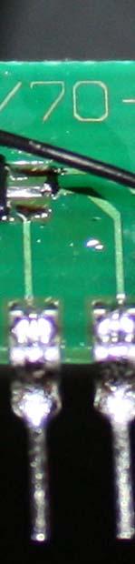
5 b. Complete construction of TL331 prototyping board. i. Solder the middle pin of RN1 to the pin 1 trace on the TL331 prototyping board. This connects the center of the voltage divider to the inverting input of the TL331. ii. Use a short section of 30GA wire wrapping wire to connect one of the other 2 pins on RN1 to the pin 5 trace on the TL331 prototyping board. This connects one side of the voltage divider to battery + 5


6 iii. Use the same techniquee to connect the remaining, unconnected pin of RN1 to the pin 2 trace of the TL331 prototyping board. It does not matter which of the 2 end pins on RN1 get connected to pin 2 and pin 5 of the TL331. This connects the other side of the voltage divider to battery. 6

.")


7 iv. Solder a 4.7K resistor between pins 4 and 6 on the TL331 prototyping board (pin 6 of the board connects to pin 5 of the TL331). This pulls the output of the TL331 up. The output of the TL331 is an open collector. It needs the pull up resistor so that it does not float. When the output of the TL331 goes low, it sinks enough current to overcome the current flowing through the pull up resistor so that the attached transistor sees a low. 7


8 v. Solder a short section of 30GA wire wrapping wire to pin3 of the prototyping board. Later you will use this wire to connect tothe non inverting input of the TL339 to the output of the NCP503 voltage regulator board. 8

")


9 2. Assemble the NCP502 prototyping board. a. Solder the NCP volt regulator (U2) to the SC 70 6 prototyping board using the same general procedure as you used for the TL331. Note: Orient the NCP502 with the 3 pin side facing left. 9
10 b. Complete the NCP502 prototyping board. i. Solder C1 between pins 1 and 2 of the NCP502 prototyping board. The + end (end w/ a bevel on the case and a line across the end) connects to pin 1 (leftmost pin). 10


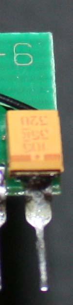
11 ii. Solder a short piece of 30GA wire wrapping wire to the negative end of C2. iii. Solder the + side of C2 to pin 5 of the NCP502 prototyping board. 11

12 iv. Solder the wire that is connected to the negative end of C2 to pin 2 of the NCP502 prototyping board. 12
13 v. Solder a short section of 30GA wire wrapping wire to connect pin 1 to pin 3 of the NCP502 prototyping board. This connects the enable pin of the NCP502 to battery +.Note: Photo only shows wire connected to pin 1. 13


14 vi. Solder 30GA wire wrapping power/ sense wires to the NCP502 prototyping board. Use wire color or markings to identify polarity. 1. Solder positive wire to pin Solder negative wire to pin 2. 14
15 2 Ceell LiP Po Low w Volltage Warn ning Circuit C t 3. Assemble the transistor t pro ototyping boaard. a. Solderr the two SST2 2222A transisstors to the SOT 23 3 transistor prototyyping board using u the same general procedure p you u used for U1 and U2.Note e: side of tran nsistor with 2 pins points down. 15

.")


16 b. Complete construction of transistor prototyping board. i. Strip the ends of a short length of 30GA wire wrapping wire and use it to connect the pad for pin 1 of Q1 to the pad for Pin 2 of Q2 (pins 2 & 4 of the transistor prototyping board).note: In this photo, the traces for pins 2 and 5 have been cut and removed as directed in the sub steps below. ii. iii. iv. Cut the trace for pin 2 of the SOT 23 3 prototyping board in 2 places near the board pin using a hobby knife. Use your soldering iron to heat the trace that you cut so it will delaminate. Apply a little solder so you get good heat transfer. Once heated, use the hobby knife to remove the piece of the trace. 16


17 v. Solder a 1k resistor across the broken trace. vi. Cut a section out of the pin 5 trace on the transistor prototyping board and use a soldering iron and hobby knife to remove the piece. 4. Attach wires to the buzzer and the LED. a. Use wire color or wire markings to identify polarity. b. The longer lead on each component is the negative side. After identifying the polarity, cut each lead short, leaving 1/8 to 3/16. 17


18 c. Solder 30GA wire wrapping wire pieces to the buzzer and the LED. d. Apply 1/16 or smaller heat shrink tube to insulate the pins. For 1/16 heat shrink, you may have to pinch the tube while it is hot to close the gaps and provide some mechanical support. 18

19 2 Ceell LiP Po Low w Volltage Warn ning Circuit C t 5. Connect the LEED and buzzer to transisto or prototypingg board. a. Solderr both negativve wires to pin 5 of the board (lower po ortion that haas been severred from the t part of thee trace that connects c to trransistor Q2).. b. Solderr the LED posiitive wire to pin p 2 of the board. c. Solderr the buzzer positive p wire to t the cut trace above pin 5 of the boarrd. This is thee trace that t pin 1 of Q2 Q is soldered d to. 19

20 6. Clean the assembled prototyping boards. Subsequent steps involve adhesives, and solder flux will interfere with adhesives. There are also other problems with leaving solder flux on the boards. 7. Plug the prototyping boards into a solderless breadboard and connect per circuit diagram. Test the circuit. Resolve any problems with each subassembly before proceeding. 8. Use clear silicone sealant to secure RN1, C1 and C2. These components need mechanical reinforcement since some of their pins are not soldered to a board or a rigid component. 9. Use epoxy glue to secure wires a. Glue the power wires to the back of the NCP502 prototyping board. b. Glue the LED and buzzer wires to the back of the Transistor prototyping board. 10. Assemble and wire prototyping boards. a. Place a piece of vinyl electric tape over the pins on the back of the TL331 prototyping board. Cover all of the pins except for the narrow part intended to fit into a socket. This prevents shorts when you glue this board to the other prototyping board. b. Glue TL331 and NCP502 prototyping boards together. i. Glue them back to back. ii. Face pins in the same direction. iii. Use silicone sealant. 20
21 c. Connect pins together with 30GA wire wrapping wire. i. Connect pin 1 of the NCP502 prototyping board to pin 6 of the TL331 prototyping board. Pins are adjacent since the boards are back to back. This is the battery + connection. ii. Connect pin 2 of the NCP502 prototyping board to pin 2 of the TL331 prototyping board. Pins are the second pins in on each end since the boards are back to back. This is the battery connection. iii. Connect pin 6 of the NCP502 prototyping board to pin 3 of the TL331 prototyping board. Count pins from the front of each board since the boards are back to back. This connects the 3.7 volt output to the non inverting input of the TL331 providing the reference voltage. d. Glue transistor prototyping board to low voltage alarm prototype board assembly. i. Cover pins on transistor prototyping board as in 10.a. ii. Orient transistor prototyping board pins at 90 to the existing pins on the low voltage alarm prototype board assembly. iii. Glue board to assembly using silicone sealant. e. Connect pins together with 30GA wire wrapping wire. i. Connect pin 4 of the TL331 prototyping board to pin 1 on the transistor prototyping board. Count pins from the front of each board. This connects the TL331 output to the base of Q1. ii. Connect pin 1 of the NCP502 prototyping board to pin 3 on the transistor prototyping board. Count pins from the front of each board. This connects pin 3 of Q1 and Q2 to battery +. iii. Connect pin 2 of the NCP502 prototyping board to pin 5 on the transistor prototyping board. Count pins from the front of each board. This connects the negative leads for the buzzer and the LED to battery. 21
22 11. Board Assembly Diagram Battery + Transistor Board NCP502 Board TL331 Board Bottom View (pins pointing towards you) 2. Transistor board view distorted to show pins 3. LED and buzzer leads not shown 4. Black chip representations indicate front of boards 5. Other components not shown 12. Test the low voltage alarm circuit. 13. Insulate assembly. a. Clip unused pins from the prototyping boards. b. Clip short unneeded portions of remaining prototyping board pins. c. Place strips of electrical tape over pin ends. d. Apply liquid electrical tape to assembly. 22
23 Testing You can test the circuit in any of the following ways: 1. If you have a variable voltage power supply, set it to about 8 volts, connecting to the circuit and decrease the voltage until the circuit emits a tone and the LED comes on. 2. Connect the circuit to a storage charged 2 cell LiPothrough a potentiometer rated for at least 1/4 watt using the following circuit. You are making a variable voltage divider so you can change the voltage the circuit sees. Turn the potentiometer until the circuit emits (or stops emitting) a tone and the LED comes on (or goes off) Cell LiPo 20K ohm Potentiometer Low Assembly
.")
24 3. Connect the circuit to a storage charged 2 cell LiPo and check the voltage periodically as you wait for the circuit to trigger. Add a servo tester and servo and set it to continuous operation (be sure to use a UBEC unless you are using a high voltage servo and servo tester). Running the servo drops the battery voltage faster than just waiting for the 3 13ma draw of the circuit to bring the battery voltage down. Be sure to check the battery voltage periodically to avoid destroying your battery by excessive discharge in case the circuit does not work properly. Hint: Use a very low capacity battery if you have one ( mah). This reduces the time required for the test. Operation Wire the circuit into the 2 cell LiPo battery before any UBEC or voltage regulator. Circuit will begin to chirp at about 7.4 volts. The chirping will transition to a steady tone. By 7.3 volts the buzzer will be on continuously. The LED will also flash and then stay on steady as voltage decreases. 24
Vout R LED2 LED1 Nr. of LEDs R Ohm Current ma Vout V Ardunio Pin9
 Tutorial AR Drone Miru Mod on Windows 7 with DX6i, Part 5 V. UFO Doctor, Aug th, 0 7. VLBA experiments with external LED at Arduino Pin9 Introduction Miru Mod 008 offered us the Visible Low Battery Alert
An open-source hardware+software project. For design files and additional documentation, please visit:
 An open-source hardware+software project. For design files and additional documentation, please visit: http://www.evilmadscientist.com/go/diavolino Support: http://www.evilmadscientist.com/forum/ Distributed
Sierra Radio Systems. Making a Keyer with the. HamStack. Project Platform
 Sierra Radio Systems Making a Keyer with the HamStack Project Platform Introduction The HamStack Project Board includes primary interface elements needed to make a high quality CW keyer. Using the LCD
Pololu 12V Step-Up/Step-Down Voltage Regulator S10V2F12
 Pololu 12V Step-Up/Step-Down Voltage Regulator S10V2F12 Overview The Pololu step-up/step-down voltage regulator S10V2F12 is a switching regulator (also called a switched-mode power supply (SMPS) or DC-to-DC
AUDIO AMPLIFIER PROJECT
 Intro to Electronics 110 - Audio Amplifier Project AUDIO AMPLIFIER PROJECT In this project, you will learn how to master a device by studying all the parts and building it with a partner. Our test subject:
Button Code Kit. Assembly Instructions and User Guide. Single Button Code Entry System
 Button Code Kit Single Button Code Entry System Assembly Instructions and User Guide Rev 1.0 December 2009 www.alan-parekh.com Copyright 2009 Alan Electronic Projects Inc. 1. Introduction... 4 1.1 Concept
Onwards and Upwards, Your near space guide. Figure 1. CheapBot Line Follower
 The CheapBot Line Follower is a plug-in single-board sensor for almost any programmable robot brain. With it, a robot can detect the presence of a black or white zone beneath its two sensors. In its simplest
LCD Prototype Circuit on Solderless Breadboard. 840 Pin Solderless Breadboard (http://www.digikey.com/ # ND)
") Solderless Breadboard Tutorial Cornerstone Electronics Technology and Robotics I Week 3 Solderless Breadboards: o Solderless breadboards are commonly used in experimentation or to make a prototype of a
Solderless Breadboard Tutorial Cornerstone Electronics Technology and Robotics I Week 3 Solderless Breadboards: o Solderless breadboards are commonly used in experimentation or to make a prototype of a
GLiPIC Ver C Assembly manual Ver 1.0
 GLiPIC Ver C Assembly manual Ver 1.0 Last Rev 1.1 Oct 30, 2001 Author: Ranjit Diol Disclaimer and Terms of Agreement As with any kit, only the individual parts supplied are guaranteed against defects and
Mini B lue M idnight
 Mini Blue Midnight 2011 by Shattered Glass Audio. All rights reserved. No part of this document may be reproduced or transmitted in any form or by any means, electronic, mechanical, photocopying, recording,
Construction Construction Instructions
 Semi-Virtual Diskette SVD Construction Construction Instructions PCB version 2.0 September 2004 Eric J. Rothfus Table of Contents Table of Contents... i Parts List...1 Construction Overview...5 PCB Construction...
TKEY-1. CW touch key. (no electromechanical contacts) Assembly manual. Last update: June 20,
 Assembly manual. Last update: June 20,") TKEY-1 CW touch key (no electromechanical contacts) Assembly manual Last update: June 20, 2017 ea3gcy@gmail.com Updates and news at: www.ea3gcy.com Thanks for constructing the TKEY-1A CW touch key Have
TKEY-1 CW touch key (no electromechanical contacts) Assembly manual Last update: June 20, 2017 ea3gcy@gmail.com Updates and news at: www.ea3gcy.com Thanks for constructing the TKEY-1A CW touch key Have
4.1 Parts and Components... IV Assembly Tips... IV Assembly Precautions... IV Required Tools, Equipment and Materials..
 IV PERSONALITY MODULE ASSEMBLY 4.1 Parts and Components............ IV-1 4.2 Assembly Tips............... IV-1 4.3 Assembly Precautions............ IV-1 4.4 Required Tools, Equipment and Materials.. IV-1
Universal Keying Adapter 3+
 Universal Keying Adapter 3+ The Universal Keying Adapter Version 3+ kit will allow you to key nearly any transmitter or transceiver with a straight key, electronic keyer, computer serial or parallel port
The Radio Control Temperature Logger (RCTL) Manual For hardware version 1.0 Manual version 1.0b
 Manual For hardware version 1.0 Manual version 1.0b") The Radio Control Temperature Logger (RCTL) Manual For hardware version 1.0 Manual version 1.0b All materials owned by Dan Gebhardt Introduction This device records the temperature of a model engine during
The Radio Control Temperature Logger (RCTL) Manual For hardware version 1.0 Manual version 1.0b All materials owned by Dan Gebhardt Introduction This device records the temperature of a model engine during
A Backlighted LCD for your K1
 A Backlighted LCD for your K1 (K1BKLTKIT) Tom Hammond - NØSS, July 27, 2006 Rev C Thanks to Wayne Burdick, N6KR for suggesting this implementation of backlighting the K1 display. APPLICABILITY This modification
Patch Bay. Model 9746 Assembly and Using Manual PAiA Corporation
 Patch Bay Model 9746 Assembly and Using Manual This second-generation 9700-series processing element for modular sound synthesizers is designed to provide great sound and excellent value. A two-section
Build Your Own Home Security System
 Build Your Own Home Security System Student Lab Guide Engineering Teaching Laboratory Name Date Lab Partner(s) NEW TERMS Electric Circuit: Electric circuits are paths for transmitting electric current,
DELUXE STEREO AMPLIFIER KIT
 ESSENTIAL INFORMATION BUILD INSTRUCTIONS CHECKING YOUR PCB & FAULT-FINDING MECHANICAL DETAILS HOW THE KIT WORKS CREATE YOUR OWN SPEAKER DOCK WITH THIS DELUXE STEREO AMPLIFIER KIT Version 2.0 Build Instructions
OpenSprinkler v2.2u Build Instructions
 OpenSprinkler v2.2u Build Instructions (Note: all images below are 'clickable', in order for you to see the full-resolution details. ) Part 0: Parts Check Part 1: Soldering Part 2: Testing Part 3: Enclosure
BrassHat Announcer Message & Sound Player Model No. BH-21A
 BrassHat Announcer Message & Sound Player Model No. BH-21A 10-Track On-Demand Recorder/Player Record up to 10 messages/sounds and play automatically or on-demand Perfect for passenger station, yard and
QUICK START GUIDE FOR DEMONSTRATION CIRCUIT 995A ADJUSTABLE LDO LINEAR REGULATOR LT3080EDD DESCRIPTION
 LT3080EDD DESCRIPTION Demonstration circuit 995A is an adjustable 1.1A linear regulator featuring LT 3080. Architected as a precision current source and voltage follower, it allows this new regulator to
Advanced Strobe 1.0 Kit
 Kit Instruction Manual Eastern Voltage Research, LLC December 2013, Rev 1 1 http://www.easternvoltageresearch.com Kit Introduction to the Kit Thank you for purchasing the Kit. If you are looking for a
DIY Assembly Manual for the LPZW.modules PO-Series Adapter Version 1.0
 DIY Assembly Manual for the LPZW.modules PO-Series Adapter Version 1.0 Introduction The LPZW.module PO-Series Adapter has five functions: hold the PO in your Eurorack supply power to the PO from bus-power
RC-210 Repeater Controller Assembly Manual
 Arcom Communications 24035 NE Butteville Rd Aurora, Oregon 97002 (503) 678-6182 arcom@ah6le.net RC-210 Repeater Controller Assembly Manual Hardware Version 3.0 Original Release Date September 13, 2004
Infrared Add-On Module for Line Following Robot
 1 Infrared Add-On Module for Line Following Robot January 3, 2015 Jeffrey La Favre The infrared add-on module allows multiple line following robots to operate on the same track by preventing collisions
Mailbox Notification Service. Created by Adam Kohring
 Mailbox Notification Service Created by Adam Kohring Last updated on 2015-06-24 10:20:07 PM EDT Guide Contents Guide Contents Overview Parts List Adafruit Products Additional Products Print the Circuit
UF-3701 Power Board Construction Guide
 Page 1/5 Soldering and Part Placement See the Chapter 3 of the MIT 6270 Manual for information on electronic assembly, including soldering techniques and component mounting. Construction Information All
Morse Code Practice Oscillator
 Features Description Keyer speed range: Limited only by keying source True Sine wave tone output Tone Volume Control Tone Frequency Control Internal Speaker 1/8 External Speaker/Headphone Jack RCA Key
W0EB/W2CTX DSP Audio Filter Construction Manual V3.02.1
 W0EB/W2CTX DSP Audio Filter Construction Manual V3.02.1 Manual and photographscopyright W0EB/W2CTX, January 01, 2019. This document may be freely copied and distributed so long as no changes are made and
MP3 audio amplifier. Build Instructions. Issue 2.0
 MP3 audio amplifier Build Instructions Issue 2.0 Build Instructions Before you put any components in the board or pick up the soldering iron, just take a look at the Printed Circuit Board (PCB). The components
Digital Circuits. Page 1 of 5. I. Before coming to lab. II. Learning Objectives. III. Materials
 I. Before coming to lab Read this handout and the supplemental. Also read the handout on Digital Electronics found on the course website. II. Learning Objectives Using transistors and resistors, you'll
Construction Manual for the W0EB/N5IB New ubitx Raduino Clone
 Construction Manual for the W0EB/N5IB New ubitx Raduino Clone Version 1.5, January 09, 2019 Manual and Images Copyright W0EB and N5IB August 03. 2018, all rights reserved. May be freely reproduced and
Alesis MMT8 16x Memory Expansion Modification (all grey model MMT8 s)
") Alesis MMT8 16x Memory Expansion Modification (all grey model MMT8 s) by Graham Meredith, 2006 Revised 13 th January 2009 gmeredith1@yahoo.com.au This modification expands the memory of the Alesis MMT8
Alesis MMT8 16x Memory Expansion Modification (all grey model MMT8 s) by Graham Meredith, 2006 Revised 13 th January 2009 gmeredith1@yahoo.com.au This modification expands the memory of the Alesis MMT8
Schematic Diagram: R2,R3,R4,R7 are ¼ Watt; R5,R6 are 220 Ohm ½ Watt (or two 470 Ohm ¼ Watt in parallel)
") Nano DDS VFO Rev_2 Assembly Manual Farrukh Zia, K2ZIA, 2016_0130 Featured in ARRL QST March 2016 Issue Nano DDS VFO is a modification of the original VFO design in Arduino Projects for Amateur Radio by
Nano DDS VFO Rev_2 Assembly Manual Farrukh Zia, K2ZIA, 2016_0130 Featured in ARRL QST March 2016 Issue Nano DDS VFO is a modification of the original VFO design in Arduino Projects for Amateur Radio by
Digital Camera Controller
 SHUTTERBUG PRO Digital Camera Controller ShutterBug Pro is a tiny accessory that helps take digital or film camera snapshots. It is ideal for photographers that need to remotely snap photos or to time
BuffaloLabs WiFi Lantern Assembly guide version 1
 BuffaloLabs WiFi Lantern Assembly guide version 1 Needed equipment: Solder iron Solder wire Cutter Wire stripper (optional) Hot glue gun Overview of the components (not including USB cable and box panels)
MICRO-TRAK 300 MANUAL VER 1.4
 MICRO-TRAK 300 MANUAL VER 1.4 The Micro-Trak 300 Version 1.4 is a miniature APRS (Automatic Position Reporting System) transmitter operating on the North American APRS frequency standard of 144.390 MHz.
Electronics Construction Manual
 Electronics Construction Manual MitchElectronics 2019 Version 3 04/02/2019 www.mitchelectronics.co.uk CONTENTS Introduction 3 How To Solder 4 Resistors 5 Capacitors 6 Diodes and LEDs 7 Switches 8 Transistors
Installation/assembly manual for DCC/Power shield
 Installation/assembly manual for DCC/Power shield The DCC circuit consists of the following components: R1/R6 R2/R3 R4/R5 D1 C2 2 kω resistor ½ Watt (colour code Red/Black/Black/Brown/Brown) 10 kω resistor
OpenSprinkler v2.1u Build Instructions
 OpenSprinkler v2.1u Build Instructions (Note: all images below are 'clickable', in order for you to see the full-resolution details. ) Part 0: Parts Check Part 1: Soldering Part 2: Testing Part 3: Enclosure
µrrc µr/c Robot Controller v1.1
 v1.1 OVERVIEW The µrrc is a simple, easy to use interface between a 3-channel R/C receiver and the OSMC H-Bridge controller for battle style robots. In principle, the µrrc can be used to drive any motor
RC Tractor Guy Controller V2.1 Assembly Guide
 RC Tractor Guy Controller V. Assembly Guide Features 0 Push button inputs Dual axis thumb sticks with built-in push button Rotary encoders with built-in push button MCU Socket to suit Meduino Mega 560
High Power (15W + 15W) Stereo Amplifier
 Stereo Amplifier") High Power (15W + 15W) Stereo Amplifier Build Instructions Issue 1.0 Build Instructions Before you put any components in the board or pick up the soldering iron, just take a look at the Printed Circuit
High Power (15W + 15W) Stereo Amplifier Build Instructions Issue 1.0 Build Instructions Before you put any components in the board or pick up the soldering iron, just take a look at the Printed Circuit
RC210 Repeater Controller Assembly Manual
 Arcom Communications 24035 NE Butteville Rd Aurora, Oregon 97002 (503) 678-6182 arcom@ah6le.net http://www.arcomcontrollers.com/ RC210 Repeater Controller Assembly Manual Hardware Version 3.3 Reproduction
LED Knight Rider. Yanbu College of Applied Technology. Project Description
 LED Knight Rider Yanbu College of Applied Technology Project Description This simple circuit functions as a 12 LED chaser. A single illuminated LED 'walks' left and right in a repeating sequence, similar
**** Never plug in your LED driver to AC power until all wiring is complete ****
 1 RapidLED Plug-n-Play Solderless Retrofit Kit Contents Overview... 1 Warnings Read Me First!... 1 Dimmable Driver Controller and Driver Output Current Adjustment... 2 Kit Assembly... 2 Attaching Your
BLUETOOTH AMPLIFIER KIT
 PRODUCT INFORMATION BUILD INSTRUCTIONS CHECKING YOUR PCB & FAULT-FINDING MECHANICAL DETAILS HOW THE KIT WORKS CREATE YOUR OWN WIRELESS SPEAKER WITH THIS BLUETOOTH AMPLIFIER KIT Version 1.2 Index of Sheets
1/Build a Mintronics: MintDuino
 1/Build a Mintronics: The is perfect for anyone interested in learning (or teaching) the fundamentals of how micro controllers work. It will have you building your own micro controller from scratch on
BITSCOPE Mixed Signal Capture Engine. Kit Assembly Guide
 BITSCOPE Mixed Signal Capture Engine Kit Assembly Guide Kit Assembly Guide Bitscope Designs Suite 1A2, 410 Elizabeth St. Surry Hills NSW 2010 Australia Table of Contents 1 Parts Identification 1 1.1 Before
RC-210 Repeater Controller Assembly Manual
 Arcom Communications 24035 NE Butteville Rd Aurora, Oregon 97002 (503) 678-6182 arcom@ah6le.net RC-210 Repeater Controller Assembly Manual Hardware Version 2.5 Reproduction or translation of any part of
Electronics Construction Manual
 Electronics Construction Manual MitchElectronics 2018 Version 1 07/05/2018 www.mitchelectronics.co.uk CONTENTS Introduction 3 How To Solder 4 Resistors 5 Capacitors 6 Diodes and LEDs 7 Switches 8 Transistors
Advanced Lantern 1.0 Kit. Introduction to the Advanced Lantern 1.0 Kit
 Advanced LED Lantern 1.0 Instruction Manual Eastern Voltage Research, LLC Introduction to the Advanced Lantern 1.0 Kit Thank you for purchasing the Advanced Lantern 1.0 Kit. This kit is an advanced microprocessor
You need the following components to assemble the Black n Wood Nixie Clock circuit board:
 You need the following components to assemble the Black n Wood Nixie Clock circuit board: Quantity Designator Description 1 Battery Battery, CR1220 1 Battery Battery holder 3 Button 1, Button 2, Button
Microsystems. SCI-6 Sound Card Interface Kit Version 1.09 January 2015
 UM Unified Microsystems SCI-6 Sound Card Interface Kit Version 1.09 January 2015 The SCI-6 interface was designed to be a low cost, high quality interface between your PC s sound card and radio transceiver.
Assembling the Printed Circuit Board for the EDE1200 Robot
 This board receives instructions from either a CBL2, a LabPro or (with an adapter cable) an original CBL. The board has two 595 shift registers (each providing 8 bits of on-board memory) and two EDE1200
Colecovision 5v Memory Mod Installation
 Colecovision 5v Memory Mod Installation The Colecovision suffers from common failure points: the power supply, power switch, and 4116 DRAM. The power supply suffers from poor soldering, the power switch
Elecraft K3 KREF3 Output Level Modification
 Elecraft K3 Revision A, September 15, 2015 Copyright 2015, Elecraft, Inc. All Rights Reserved Introduction This modification increases the output levels from the KREF3 Reference Oscillator to provide proper
Pacific Antenna Easy TR Switch Kit
 Pacific Antenna Easy TR Switch Kit Kit Description The Easy TR Switch is an RF sensing circuit with a double pole double throw relay that can be used to automatically switch an antenna between a separate
Part 2: Building the Controller Board
 v3.01, June 2018 1 Part 2: Building the Controller Board Congratulations for making it this far! The controller board uses smaller components than the wing boards, which believe it or not, means that everything
Parts List: Part # Tools List: Instructions:
 Parts List: Part # 1 pair of Dayton Audio B652s 300-652 1 Dayton Audio DTA-2 amplifier 300-385 1 MP3 module 320-350 1 7805 +5 VDC voltage regulator 7805 1 12 VDC 2A power supply 129-077 1 2.1 mm panel
Chill Interface PCB Assembly Instructions
 ExcelValley Chill Interface PCB Waveblaster Module MIDI Interface Board Chill Limited Edition V2 Assembly Kit Standalone midi interface board for Waveblaster synthesizer modules. Suitable for most Waveblaster
Triori Game PART NO
 Triori Game PART NO. 2207865 -History Almost everyone knows the tic tac toe but few know the game Triori. Triori or Triara as it is called, is an ancient Greek game that was played in the sand or the streets
A4988 Stepper Motor Driver Carrier, Black Edition
 A4988 Stepper Motor Driver Carrier, Black Edition A4988 stepper motor driver carrier, Black Edition, bottom view with dimensions. Overview This product is a carrier board or breakout board for Allegro
BS2p40tm OEM Module. Surface mount/through hole kit By Robert L. Doerr. Manual Revision.5
 BS2p40tm OEM Module Surface mount/through hole kit 2006 By Robert L. Doerr Manual Revision.5 NOTE: The BASIC Stamp and the BS2p40 and Interpreter chip are trademarks of Parallax. This partial kit allows
3 pyro output datalogger altimeter with an ATmega 328 microcontroller Kit assembly instructions
 3 pyro output datalogger altimeter with an ATmega 328 microcontroller Kit assembly instructions Version date Author Comments 1.0 29/05/2013 Boris du Reau Initial version Rocket Type Micro-max Model Mid
HS-27 Manual 5/2/2013. Neuralynx, Inc. 105 Commercial Drive, Bozeman, MT Phone Fax
 5/2/2013 Neuralynx, Inc. 105 Commercial Drive, Bozeman, MT 59715 Phone 406.585.4542 Fax 866.585.1743 www.neuralynx.com support@neuralynx.com Table of Contents 1 Headstage 27 Overview... 3 2 Glossary...
A4988 Stepper Motor Driver Carrier
 A4988 Stepper Motor Driver Carrier A4983/A4988 stepper motor driver carrier with dimensions. Overview This product is a carrier board or breakout board for Allegro s A4988 DMOS Microstepping Driver with
700 Series 200 Amp Clamp Meters
 700 Series 200 Amp Clamp Meters #61-700 #61-701 #61-702 1 2 3 6 5 7 4 8 1. Non-contact voltage (NCV) (#61-701 and #61-702) With the NCV tab on the tip of the clamp close to an AC voltage, press the NCV
Propeller Project Board USB (#32810)
") Web Site: www.parallax.com Forums: forums.parallax.com Sales: sales@parallax.com Technical: support@parallax.com Office: (916) 624-8333 Fax: (916) 624-8003 Sales: (888) 512-1024 Tech Support: (888) 997-8267
Web Site: www.parallax.com Forums: forums.parallax.com Sales: sales@parallax.com Technical: support@parallax.com Office: (916) 624-8333 Fax: (916) 624-8003 Sales: (888) 512-1024 Tech Support: (888) 997-8267
E-11 Trooper Blaster upgrade Hyperdyne Labs 2009
 E-11 Trooper Blaster upgrade Hyperdyne Labs 2009 http://www.hyperdynelabs.com This kit is for a Hasbro, Kenner, PVC, or other E-11 prop. Using our state-of-the-art technology and engineering experience,
Constructing a Low-Cost Mobile Eye Tracker
 ==== Constructing a Low-Cost Mobile Eye Tracker ==== Section 1: Introduction This is a detailed set of instructions on how to build a low-cost mobile eye-tracking system from off-the-shelf components.
K1EL Morse Code Practice Oscillator CPO
 Features This is an oscillator not a Morse keyer Input source can be a keyer or straight key Near Sine wave tone output CPO Tone Volume Control CPO Tone Frequency Control Use headphones or external speaker
USB Stamp Adapter Board
 User Manual Engineering» Design» Product Blue Wolf, Inc. 9179 W. State Street Garden City, ID 83714 Revision History Version # Release Date Revision/Release Comments 1.0 3/7/2011 Initial draft for release.
HS-27-Mini. Headstage preamplifier providing 27 channels of unity gain amplification.
 HS-27-Mini Headstage preamplifier providing 27 channels of unity gain amplification. 9/16/2013 Neuralynx, Inc. 105 Commercial Drive, Bozeman, MT 59715 Phone 406.585.4542 Fax 866.585.1743 www.neuralynx.com
Assembling and testing electronic circuits. Outcome one
 006 UNIT 036 Assembling and testing electronic circuits Learning outcomes 1 2 Know how to assemble and test electronic circuits Performance evidence must be the main form of evidence gathered. Candidates
GPS Series. Build a GPS Smart Logger. By Michael Simpson. As seen in November 2008 of Servo Magazine Pick up an issue at
 GPS Series By Michael Simpson Build a GPS Smart Logger As seen in November 2008 of Servo Magazine Pick up an issue at www.servomagazine.com I recently did a GPS series covering various GPS modules and
QUASAR KIT No DIGITAL DOWN TIMER 99 MIN WITH PIC
 QUASAR KIT No 1173 - DIGITAL DOWN TIMER 99 MIN WITH PIC KIT 1173 is a digital countdown timer based on a micro controller, thus securing reliability and excellent operation under any circumstances. It
Adafruit USB Power Gauge Mini-Kit
 Adafruit USB Power Gauge Mini-Kit Created by Bill Earl Last updated on 2017-07-14 11:55:04 PM UTC Guide Contents Guide Contents Overview Assembly Basic Assembly Solder the female connector. Solder the
B.Y.O.C. MK2 Kit Instructions
 B.Y.O.C. MK2 Kit Instructions Parts Checklist.....page 2 Populating the Circuit Board......page 3-5 Assembly......page 6 Wiring......page 7 Installing the LED and Mounting the PCB...page 8-9 Finish up...page
Assembly of the TACOS WAT-910BD Housing v2
 1) Circuit Diagram 2) Assembly of PCB a)tools Required. Only simple hand tools are necessary to complete the assembly of the PCB. - Soldering Iron and solder - Needle nose pliers - Wire clippers/trimmers
The PUMPKIN LIGHT LED
 The PUMPKIN LIGHT LED PUMPKIN LIGHT LED By Mark McCuller Email: mcculler@mail.com DESIGN SUMMARY The PUMPKIN LIGHT LED By: Mark McCuller The Pumpkin Light LED is a battery-powered device that illuminates
QRPometer Assembly Manual Copyright 2012 David Cripe NM0S The 4 State QRP Group. Introduction
 QRPometer Assembly Manual Copyright 2012 David Cripe NM0S The 4 State QRP Group Introduction Thank you for purchasing a QRPometer. We hope you will enjoy building it and and find it a useful addition to
Freeze the Dizz Jameco Part No
 Freeze the Dizz Jameco Part No. 2161431 This project is based on a children s arcade game. Twenty LEDs are placed on a ring and each takes turn to light up forming a rotating light spot. If a push-button
AXE Stack 18. BASIC-Programmable Microcontroller Kit. An inexpensive introduction to microcontroller technology for all ability levels
 Ltd AXE Stack 18 BASIC-Programmable Microcontroller Kit a division of An inexpensive introduction to microcontroller technology for all ability levels Free Windows interface software Programmable in BASIC
Wireless Saber Sound Kit Assembly and Instruction Document
 Wireless Saber Sound Kit Assembly and Instruction Document INTRODUCTION The wireless saber sound kit allows you to add motion-interactive sound effects to your toys and props. With the aid of a host PC,
PROTO BOARD SETUP Here is a schematic of the circuit we will build.
 PROTO BOARD SETUP Here is a schematic of the circuit we will build. Cut off the connector from the end of your 5V supply and strip the insulation off for one half inch. Tin the striped ends with solder.
TEST. "fingerprint" being tested matches that. then the IC is considered. defective. The Analogic IC
 ANALOGIC IC TESTER Check out digital and analog ICs with this inexpensive home -brew combo tester THE ANALOGIC IC TESTER IS A DEvice designed to test both analog and digital integrated circuits. Most IC
Shack Clock kit PCB Revision: QCU Rev 1 or QCU Rev 3
 1. Introduction Shack Clock kit PCB Revision: QCU Rev 1 or QCU Rev 3 Thank you for purchasing this QRP Labs Shack Clock kit. The kit uses the same PCB and bag of components as some other QRP Labs kits.
ASUS Zen Pad 10 Micro USB Port & Camera Replacement
 ASUS Zen Pad 10 Micro USB Port & Camera Replacement Remove the motherboard and replace the camera and micro USB port. Written By: Mr Circuit ifixit CC BY-NC-SA www.ifixit.com Page 1 of 13 INTRODUCTION
Insert the male, 90 angled, 2x10 connectors into the corresponding 2x10 sockets and put them in place, flat under the PCB. Solder.
 MC624 Assembly guide Safety warning The kits are main powered and use potentially lethal voltages. Under no circumstance should someone undertake the realisation of a kit unless he has full knowledge about
ARRL ETP Solder Hour Clock Kit Construction Manual
 ARRL ETP Solder 101 24-Hour Clock Kit Construction Manual Do a complete parts check cross checking the individual parts against the parts list. Pay particular attention to the color code for the resistors:
RB-Pol V, 300mA Step-Down Voltage Regulator D24V3F3
 RB-Pol-220 3.3V, 300mA Step-Down Voltage Regulator D24V3F3 The compact (0.4 0.5 ) D24V3F3 switching step-down (or buck) voltage regulator takes an input voltage between 4.3 V and 42 V and efficiently reduces
Assembly Instructions for the KA Electronics Elliptic Equalizer
 Assembly Instructions for the KA Electronics Elliptic Equalizer Install IC sockets Elliptic Equalizer PC Board Stuffing Guide Place the PC Board on the work bench silkscreen side face up. Place twelve
4.0 Blue LED DCF77 Clock documentation
 4.0 Blue LED DCF77 Clock documentation 1. LED Clock Main Board PCB mounting: Mount and solder the eight wire bridges. Mount and solder resistors R16, R18, R20, R22. Mount and solder capacitors C1 C3 (pitch
SILICON DESIGNS, INC Model 1210 ANALOG ACCELEROMETER
 SILICON DESIGNS, INC Model 1210 ANALOG ACCELEROMETER SENSOR TYPE: Capacitive Micromachined Nitrogen Damped Hermetically Sealed ±4V Differential Output or 0.5V to 4.5V Single Ended Output Fully Calibrated
University of Florida EEL 4744 Drs. Eric M. Schwartz, Karl Gugel & Tao Li Department of Electrical and Computer Engineering
 Page 1/9 Revision 1 OBJECTIVES In this document you will learn how to solder and to debug a board as you are building it. REQUIRED MATERIALS Website documents o UF 68HC12 Development Board Manual (board
Alesis MMT8 16x Memory Expansion Modification (Black model MMT8 s) Equipment. Components required. Other bits:
 Equipment. Components required. Other bits:") Alesis MMT8 16x Memory Expansion Modification (Black model MMT8 s) by Graham Meredith, 006 Revised 15 th January 009 gmeredith1@yahoo.com.au This modification expands the memory of the Alesis MMT8 to 16x
Alesis MMT8 16x Memory Expansion Modification (Black model MMT8 s) by Graham Meredith, 006 Revised 15 th January 009 gmeredith1@yahoo.com.au This modification expands the memory of the Alesis MMT8 to 16x
Make Kits and Casemods
 Make Kits and Casemods This weekend, you ll learn how to make a Minty Boost usb charger and a Daisy mp3 player. After you put these together you can put them into customized cases. I made my charger fit
SRI-02 Speech Recognition Interface
 SRI-02 Speech Recognition Interface Data & Construction Booklet The Speech Recognition Interface SRI-02 allows one to use the SR-07 Speech Recognition Circuit to create speech controlled electrical devices.