HT2000 Transverter Installation & Operation Manual
|
|
|
- Alexis Carter
- 6 years ago
- Views:
Transcription


1 HT2000 Transverter Installation & Operation Manual 1
2 A message from the team at Heart Transverter S.A. Thanks for your recent purchase of the HT2000 Power inverter in combination with the HTREM Remote Panel. Heart Transverter S.A. takes great pride in manufacturing high quality products specially design to meet the demand of today s busy world. You have taken the first step for achieving a better world, and saving energy; the HT2000 and the HTREM will allow you to manage the energy demand in your house or small appliances, by providing safe connection, UPS support, power factor correction and grid energy injection. If you have any questions about the HT2000 Power Module or HTREM Panel, please contact Heart Transverter at (direct). For technical support and additional information about Heart Transverter S.A. products, visit our Web site at or us at sales@transverter.com CONFORMS TO UL STD 1741 CERTIFIED TO CSA C22.2 No HEART TRANSVERTER S.A. MODEL: HT2000 2
3 Table of Contents IMPORTANT SAFETY INSTRUCTIONS 5 FCC Information to the User.7 General Overview..8 Hardware description DC SIDE.. 9 AC SIDE Getting Started with your HT Installation 13 Hardware Installation (mounting).13 AC power installation.13 Brief description of the AC Panel box.14 AC GRID source check.15 AC access panel removal.17 AC wiring check.20 AC access panel placement 20 DC Power Installation 21 Brief description of the DC Inputs 21 DC INPUTS VBA & VBB 21 DC INPUT V50.25 DC source check.25 3
4 Enclosure Grounding...25 Terminal covers..25 HTREM Module..26 Maintenance Instructions.26 Appendixes.29 Unit ratings.27 Mechanical Drawings...29 Installation Drawing..30 HTREM Mechanical drawing..31 Utility Interactive 32 Stand Alone 32 Utility - interactive with charge control Stand alone with charge control.32 4
5 IMPORTANT SAFETY INSTRUCTIONS Save these instructions This manual contains important instructions for Models HT-2000 and HT-2000T that shall be followed during installation and maintenance of the HT-2000 and HT-2000T models. Read all of the instructions and cautions in the manual before operating the HT2000. This guide includes safety operational instructions for the HT2000 Transverter. The following safety symbol conventions are used throughout this guide to indicate potentially dangerous conditions and/or important safety instructions. Please be advised that, for all Transverter installations, qualified personnel are required. Do not attempt to perform this installation on your own. The HT2000 produces voltages and currents capable of causing severe injury or even death. Caution must be taken when installing and operating the HT2000. Ensure that all power (both AC and DC) have been disconnected BEFORE installing, servicing, or removing theht2000transverter. Do not install the HT-2000 on, near or over combustible surfaces. Do not install the HT-2000 on a confined space where there is presence of combustible fumes! Always follow the proper electrical code regulations during installation for proper wiring (i.e. ANSI/NFPA 70 for United States or CEC for Canada) 5


6 Symbols Caution! Watch! Take notice! High voltage risk High temperature 6
7 FCC Information to the User This equipment has been tested and found to comply with the limits for a Class B digital device, pursuant to part 15 of the FCC Rules. These limits are designed to provide reasonable protection against harmful interference in a residential installation. This equipment generates, uses and can radiate radio frequency energy and, if not installed and used in accordance with the instructions, may cause harmful interference to radio communications. However, there is no guarantee that interference will not occur in a particular installation. If this equipment does cause harmful interference to radio or television reception, which can be determined by turning the equipment off and on, you are encouraged to try to correct the interference by one or more of the following measures: Reorient or relocate the receiving antenna. Increase the separation between the equipment and the receiver. Connect the equipment into an outlet on a circuit different from that to which the receiver is connected. Consult the dealer or an experienced radio/tv technician for help. Changes or modifications not expressly approved by the party responsible for compliance may void the user s authority to operate the equipment. 7
8 General Overview The HT2000 power module is a Universal Power Interface that, by using intense amounts of logic, can bi-directionally transfer power between any combinations of its four connections. Each power module has two DC connections and two AC connections. Each DC terminal can connect to anything from volts to things like batteries of any chemistry, solar panels, fuel cells, DC wind generators, alternators, etc. The AC connections are for AC loads, the Grid and generators. The HT-2000 power module requires the HTREM to be operated, with the control panel in place, it s very easy to operate the unit. The user can read the power consumption, battery status and also, send information to a personal computer for further analysis. Hardware description The HT-2000 is a 2 kw power interface and UPS system. It serves as a bi-directional interface between any two DC sources or loads between 10 to 50 volts, also an AC interface with an input or output of volts in single phase. The HT 2000 supports 2000 watts continuously, and is compatible with 60 Hz AC power. The unit has automatic power factor compensation, pure sine wave output, precisely regulated AC and DC outputs, line conditioning, surge and brownout protection. The unit is divided in several sections for a convenient AC DC installation. 8


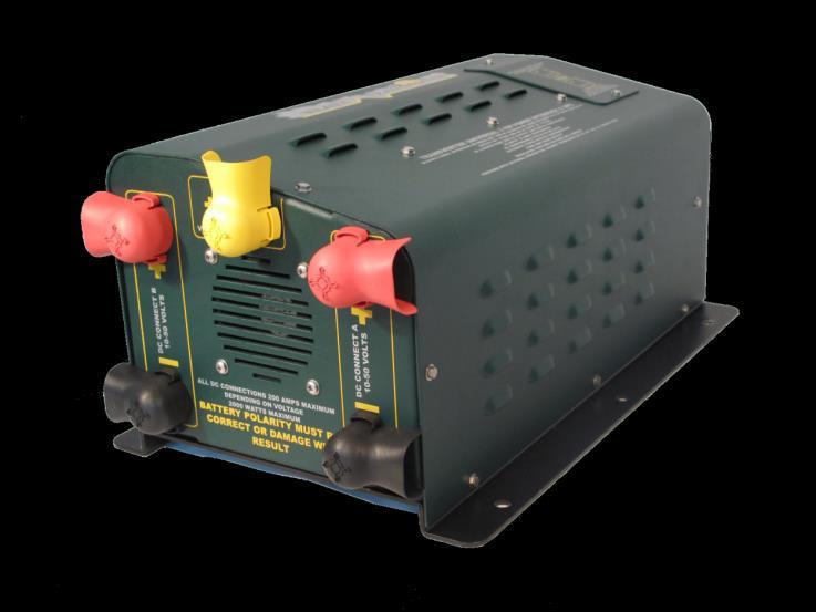
9 DC SIDE DC Connection V50 for multiple units DC Connection for solar panels, VBB. DC Connection for batteries, VBA. Figure 1. DC connection side The unit can allow the user to connect solar panels and batteries on these terminals, also the V50 terminal allows multiple module connections, this terminal works as a power transfer between the units. 9

10 AC SIDE AC Output of the unit (A) AC Input (from the GRID) (B) DOWN connector (C) UP connector for HTREM (D) Ground lung or chassis ground (E) Figure #2. AC connection side The unit has several connection points on the AC side A. This is the output of the unit, here you can connect your AC loads, it is highly recommended that after the AC output a circuit breaker and a UL 943 listed Ground Fault Circuit Interrupter, GFCI, to be connected in series, this will allow extra security to the people using the system. B. This is the input of the unit, in this section the GRID gets connected, this input must be protected by the means of a circuit breaker. 10
11 C. This is the DOWN connector, this connector allows to connect multiple units in a daisy chain fashion. The DOWN connector connects to the next unit UP connector. D. This is the UP connector, on this point the HTREM must be connected to allow the operation of the unit. E. This point is the grounding lung, in local installation this point must be connected to ground. Getting Started with your HT2000 HT Identification For future easy troubleshooting, and easy access information, please fill this sheet for future references. HT2000 Identification TAG Date Purchased: Dealer Name: Dealer Address: Dealer phone number: HT-2000 Serial number(s) : HT-2000 HW Revision(s): 11
12 HTREM Identification TAG HTREM Serial number: HTREM HW revision: HTREM Revision Firmware: Date: Notes: Your 13 digit serial number can be found on the side of the HT-2000 (HT000xxxxxxxx), for the HTREM this can be found on the bottom of the unit (TR000xxxxxxxx). 12
13 Installation The HT-2000 power module must be installed by a qualified electrician, to avoid electrical wiring mistakes as well as to assure that the HT-2000 will operate in a safe manner. Care should be given in picking a place for the HT-2000 to operate. It is desired to have the power modules reside in a well-ventilated, dry area, away from the weather elements. Ideally, they are to be mounted on the same wall as your existing facility circuit breaker panel and near your DC input sources. Short connections between the DC inputs and the HT-2000 result in power saving. Hardware Installation (mounting) The HT-2000 should be mounted on a vertical wall, this will prevent the entrance of water to the unit or the accidentally intrusion of foreign material inside the unit. Also the HT-2000 has a side ventilator; this section must be free to allow the proper ventilation and cooling of the unit when a heavy load is being used. Also, for the mounting, six 3/8 bolts are needed to secure the device firmly to the mounting surface. (Check appendix drawings for an example on a wall installation) AC power installation Prior to making the electrical installation, verify that all breakers are turned off, all the installation to the HT-2000 must be without voltage. Placing energized cables during the installation of the system is dangerous and can create a voltage arc that can damage the unit and also can cause severe shock to the installer or user. The HT-2000 must be connected to a breaker box on the input of the 13
14 unit, the following diagram can be followed to have an idea of an example installation of the unit (Figure #3) Brief description of the AC Panel box The HT-2000 has a connection box that allows the wiring of the system to the AC Grid, and to supply AC power to the different loads. AC INPUT (ACIN): This is where the grid connects to the unit, this section supplies energy to the HT-2000 and allows the unit to function with AC power. This input can accept voltages in the range from 105 to 132 volts AC, with a working frequency of 60 Hz. An important feature is that, if the system is installed in a remote location, an AC power generator can be connected to this input. AC Output (ACOUT): This is the output of the unit, on this section the user can get 117 VAC at 60 Hz pure sine wave, this output must be connected to a circuit breaker and then to a GFCI outlet. Note: The GFCI will detect if there is a ground fault. The GFCI provides additional safety for the user. Such electrical GFCI it s NOT provided with the HT-2000 unit. A ground-fault circuit-interrupter must comply with the Standard for Ground-Fault Circuit-Interrupters, UL 943. A tested unit that works with the HT-2000 system is GF20ILA from Hubbell, this GFCI has a capacity of 20 A. Other types of GFCI can be used as long as they are UL 943 Listed and with a capacity to support 20 amps in current. 14
15 AC GRID source check This verification of voltages must be made on the main breaker panel box. The AC Grid connection to the HT2000 needs to be verified prior to the installation of the HT2000 and TREM units. That is, a quick check of the proper 1 or 2 phase AC wiring from the incoming Grid connection to make sure that single or two phase AC grid connection yields the correct voltage range below: AC Grid Phase 1 Voltage (with respect to the AC Neutral) o 125 VAC. AC Grid Phase 2 Voltage (with respect to the AC Neutral) to 125 VAC. AC Two Phase Voltage (with respect from Phase 1 HOT to Phase 2 Hot) to 250 VAC. If the voltages are not in these ranges, please make an additional verification of the voltage grid. If the system HT-2000 is connected and the voltages are not in the proper range, damage to the unit can occur. 15
 20 SWD 2 0 S W D Green White All the wire connections must be made with AWG #10 GFCI Outlet White AC Connection box on the HT-2000 Figure #3.")
16 Line Neutral AC AC AC Power In (MAIN PANEL) AC power Out (Your breaker box can be bigger with more circuit breakers inside!!!!) 20 SWD 2 0 S W D Green White All the wire connections must be made with AWG #10 GFCI Outlet White AC Connection box on the HT-2000 Figure #3.Circuit breaker connection on the HT-2000 and output breaker box. Note: The input and output breakers must be installed to ensure safety of the equipment and your electrical appliances, such breakers are NOT supplied with the HT-2000 unit. You can use breakers rated at 20 amps, such as the CH120 from Eaton. Other types of circuit breakers can be used as long as they are UL Listed. The circuit breaker for the output AC 16


17 circuit should be rated at 20 amps and the circuit breaker for the input AC circuit should be rated at 30 amps. AC disconnect and over current protection The input and output circuit breakers provide over current protection and can be used as a manual disconnect by switching the breakers off. AC access panel removal When the AC voltages are checked and within the specified ranges, the AC access panel can be removed to begin the hard wire of the unit, the access panel is located on the front section of the unit and has 2 hex screws. After removing the screws the wires can be fed into the box and connected as properly. Figure #4.AC access panel removal. 17
18 After the panel is removed, the wiring compartment can be accessed, there are 5 connections, and from TOP to BOTTOM are as follows: (5) AC INPUT LINE (4) AC INPUT NEUTRAL (3) GROUND (2) AC OUTPUT LINE (1) AC OUTPUT NEUTRAL Note: The diagram on figure #3 can be followed for reference, follow the number references. This compartment allows the installer to feed the cables to connect the unit to the grid and to the loads, a Scotchlok PIN Terminals (P/N: MNG10-55P) from 3M can be used to allow a faster easy installation (these pins are not supplied with the HT-2000, and can withstand an amperage equal to the wire AWG 10) To place the terminal on the wire: 1. Strip away the end 3/8 inch of wire insulation. 2. Make the crimp using the a recommended crimp tool, like TH- 440, TH-450, or TR-490 all of them from 3M The figure #5 shows a typical installation and wiring. 18

19 Figure #5 AC Output and Inputs wired If the terminals are not going to be used, the wire can be feed directly into the connector following these instructions. 1. Loosen the tightening bolts on the connector 2. Strip away3/8 inch of wire insulation 3. Place the wire inside the connector 4. Tighten the screw to secure the cable The unit requires a cable clamp connector knockout conduit fitting to secure the wire in place and to avoid displacement, such cable clamps are not supplied with the unit but must be used to ensure proper installation. The proper size is a ½ diameter conduit clamp connector. 19
20 WARNING! a. These instructions must be followed and performed while the unit is not energized or connected to batteries, due to risk of electrical shock b. Do not connect the terminals backwards, by doing so, the unit can suffer damage voiding the warranty. All installations must be performed by a qualified technician. AC wiring check After the wires are connected to the system, verify for connection order, verify color code of the cables according to your current electrical code, also, check that the screws that holds the cables in place are tight enough to secure the cable. All this cable connections must be made with a cable size 10 AWG. Also, the grounding terminal in the AC connection box can support two wires 12 AWG. AC access panel placement After the wires are installed, in place and properly secure, follow the back sequence from AC panel removal to finish the AC electrical installation of the unit (figure 4). AC Grounding The HT-2000 has an AC grounding lug located on the external chassis; this ground point must be used to ground the unit locally at the installation place. 20
21 DC Power Installation The DC power is another important section for the functionality of the HT This power can be supplied by batteries (any configuration and chemistry), solar panels, energy cells, or fuel powered electric generators or wind generators. Brief description of the DC Inputs The system has a series of DC connections that allows the HT-2000 receive and feed different types of DC power sources. DC INPUTS VBA & VBB These inputs are coded RED and BLACK, and their purpose is to allow the unit to connect to different power DC sources like batteries, power cells or solar panels. The voltage range for these terminals is between 10 and 50 volts. These connections must be made using at least a 4 AWG wiring. VBA is normally connected to batteries and VBB is normally connected to solar panels. Note: If the power source comes from a bank of batteries configured in 12 V modes, the amount of current that can travel through these wires can go as high as 200 Amps. For this case, a 0 AWG wire must be used and properly secure to the terminal. ADDITIONAL EQUIPMENT THAT MUST BE PROVIDED FOR THE DC INPUTS Additional equipment must be provided to provide the DC disconnect, over current protection and ground fault protection for solar arrays. You can use DC UL rated circuit breakers for the battery connection as well as for the solar panel connection. Many solar combiner boxes include these DC UL listed circuit breakers. You can also use UL listed DC rated fuses with listed fuse blocks. 21
22 WARNING: This unit is not provided with a GFDI device. This inverter and charge controller must be used with an external GFDI device as required by the Article 690 of the National Electrical Code for the installation location. This system could have the battery negative or the solar negative connected to ground. If there was some damage to the insulation of the positive wire from the solar panels and it was touching a piece of metal of the structure of the building that was grounded then it could act like a small arc welder and possibly cause a fire. If you have the GFDI device installed then it will automatically detect this condition and disconnect the negative wire of the solar panels and protect against this situation. Some examples of high quality GFDI devices you could use from MIDNITE SOLAR are MNDC-GFP80 Breaker and MNDC-GFP63 Breaker. There are several configurations of batteries that can be used with the HT-2000, here are some examples of interconnection with the unit: 1. The first example it s an interconnection of a single 12 V battery or a bank of 12 batteries to increase the current. 22
23 Solar Panel 120 A 215 A HT-2000 Solar Panel 12 V 120 A 215 A HT V 12 V 12 V Figure #6. Sample configuration for 12 volts. 23


24 2. This configuration is for a 24 V battery bank using 12 V batteries in series. Solar Panel 120 A 200 A HT V 12 V 12 V 12 V Figure #7. Sample configuration for 24 V using 12 V batteries. The circuit breakers or fuses should be rated for DC and UL Listed. These are not supplied with the HT-2000 unit. 24
25 DC INPUT V50 This connection is a special feature of the HT This output/input allows the unit to distribute power between multiple HT-2000 units connected together. This terminal allows the units to balance the power between each another. It is also used for Telecom devices to get power at a stable 48 V DC. DC source check Prior to connecting the DC power to the unit, verify the voltages that will be connected to the system, both voltages sources must be in the range from volts DC. After the voltage is checked, the actual installation can proceed. The system allows the connection of solar panels in terminal VBB, batteries must be connected on terminals VBA. Figure #6 explains in a graphic manner how the system must be connected when these types of power sources are used. Enclosure Grounding After the AC inputs and the DC inputs are in place, installed and verified, the grounding can be installed, the grounding lug it s located on the AC side of the unit, a green wire must be installed to properly ground the chassis. A cable AWG #8 must be used. Terminal covers The terminals covers are for the DC connection side, when the DC power source are properly installed and bolted to the terminals. The covers should be in place to avoid accidental contact with metal objects. The batteries have a capacity to provide enormous currents if they are short circuited. 25
26 HTREM Module Its highly recommend to install the HTREM in an easy to access location. It is designed to be easily flush mounted on any flat surface such as a wall or desktop, and must be located within 2 meters of the HT-2000 power module. The Standard Ethernet Cable provided must be routed/connected to the HTREM and then four screws anchor the REM module to the desired flush surface. To access advanced features of the HT2000 power module, the HTREM can be connected to a computer via the front/rear panel USB connectors. In this case the HTREM must be within 5 meters (USB2.0 Specification) of the computer you will be using. Note: Avoid excess pressure when installing the screws to secure the HTREM module. If too much torque its applied, the polycarbonate face plate may break causing damage to the unit. Maintenance Instructions Prior to the maintenance activities, verify the safety instructions at the beginning of this manual. Also, if the unit requires servicing, disconnection of all electrical power supplies is a must. The HT-2000 requires very little maintenance, since the internal parts of the unit are not serviceable, the recommended maintenance activities is to verify that there is no dust on top, side and bottom of the unit, also, verify that the exhaust vent it s not blocked or dirty. Additionally, with constant operation and normal vibration, the battery and solar array connectors might get a little loose, once in a while, the tightening must be checked to ensure proper connection. If the terminals connections appear to have concentrations of corrosion, use a brush to clean and to remove these residues. These adjustments must be made with the unit power off from the AC Grid. 26
27 27
28 STORAGE TEMPERATURE -20 C to 50 C OPERATING TEMPERATURE -6 C to 43 C DIMENSIONS (H X L X W ) 8.2" X 18.75" X 11.8" BOX SIZE (H X L X W ) 11.0" X 14.5" X 21.0" BOX WEIGHT lb (15.1 kg) CONFORMS TO UL STD 1741 CERTIFIED TO CSA C22.2 No HEART TRANSVERTER S.A. MODEL: HT
29 Appendixes Mechanical Drawings 29
30 Installation Drawing 30
31 HTREM Mechanical drawing 31
32 32
Nature Power Inverters. Modified Sinewave 1000w/1500w True Sinewave 1000w/2000w. Owner s Manual
 Nature Power Inverters Modified Sinewave 1000w/1500w True Sinewave 1000w/2000w Owner s Manual Modified Sinewave Series True Sinewave Series For safe and optimum performance, the Power Inverter must be
5 B&W Rear View System Camera
 5 B&W Rear View System Camera Instruction Manual MODEL: CA453 www.lorexcctv.com Copyright 2007 LOREX Technology Inc. Thank you for purchasing the Lorex 5 Black & White Rear View System Camera. This system
Modified Sinewave Series. Power Inverter 1000/1500 MW 1210, MW1215. True Sinewave Power Inverter 1000/2000 SW 1210, SW 1220.
 Modified Sinewave Power Inverter 1000/1500 MW 1210, MW1215 True Sinewave Power Inverter 1000/2000 SW 1210, SW 1220 Owner s Manual Modified Sinewave Series True Sinewave Series 1. INTRODUCTION Thank you
Installation/User Manual
 Installation/User Manual APsystems YC500-A Photovoltaic Grid-connected Inverter Version 4.1 8/15 APsystems 600 Ericksen Ave. NE Ste 200 Seattle, WA 98110 TEL: 844-666-7035 EMAIL: info@apsystems.com WEB:
Satellite INSTALLATION GUIDE
 N3 Satellite INSTALLATION GUIDE ! WARNING! Shock Hazard. May result in serious injury or death. Turn power OFF at circuit breaker or remove fuse. Damage to this product caused by wiring with power on voids
The following symbols are used to show dangerous operation or handling. Make sure you understand them before reading the guide.
 Safety Instructions Before use Thank you very much for purchasing this product. This product is an interface box called "Connection & Control Box" for EPSON short throw projectors. For your safety, read
PV Rapid Shutdown device
 PV Rapid Shutdown device Installation and Operation Manual Solis-RSD-1G(1:1) Solis-RSD-1G(2:2) Manufacturer: Ginlong (Ningbo) Technologies Co.,Ltd., Ningbo, Zhejiang, P.R.China US Office: 565 Metro Pl.
INSTALLATION INSTRUCTIONS
 INSTALLATION INSTRUCTIONS READ THIS MANUAL CAREFULLY! FAILURE TO INSTALL THIS EQUIPMENT PER THESE INSTRUCTIONS WILL VOID THE WARRANTY. AM16904-1 Rev. C pg. 1 of 12 SPECIAL NOTICES The following notices
The following symbols are used to show dangerous operation or handling. Make sure you understand them before reading the guide.
 Safety Instructions Before use Thank you very much for purchasing this product. This product is an interface box called "Connection & Control Box" for EPSON short throw projectors. For your safety, read
Touch Panel Dimmer MH-P511. Introduction
 Touch Panel Dimmer MH-P5 Introduction Touch Panel Dimmer is a wall switch with built-in Z-Wave module. It supports basic command class, association command class, which can control all associated devices
SA-150, SA-300 Series Pure Sine Wave Inverter User s Manual
 SA-150, SA-300 Series Pure Sine Wave Inverter User s Manual List of contents 1. IMPORTANT safety Information... 1 1-1 General Safety Precautions.. 1 1-2 Battery Precautions 1 2. Features. 2 2-1 Electrical
INSTALLATION INSTRUCTIONS
 INSTALLATION INSTRUCTIONS Adaptor Model No. CZ-CFUNC1U For your safety Read the following instructions carefully, and carry out secure installation and electrical work. The precautions given in this manual
Mercury Helios ASSEMBLY MANUAL & USER GUIDE
 Mercury Helios ASSEMBLY MANUAL & USER GUIDE TABLE OF CONTENTS INTRODUCTION...1 1.1 MINIMUM SYSTEM REQUIREMENTS 1.1.1 Apple Mac Requirements 1.1.2 PC Requirements 1.1.3 Supported PCIe Cards NOTE: Boot Camp
AcquiSuite Ally 12 & 48 Advanced Multi-Circuit Meter
 AcquiSuite Ally 12 & 48 Advanced Multi-Circuit Meter Install Guide Revision C (12/18) DANGER HAZARD OF ELECTRIC SHOCK, EXPLOSION, OR ARC FLASH Revision C (12/18) Turn off all power supplying equipment
Installation/User Manual
 Installation/User Manual APsystems YC500i Photovoltaic Grid-connected Inverter Version 1.0 7/16 APsystems 600 Ericksen Ave. NE Ste 200 Seattle, WA 98110 TEL: 844-666-7035 EMAIL: info@apsystems.com WEB:
MONOPRICE. ShowPony 12-Watt LED Derby FX Light (RGBW) User's Manual P/N
 User's Manual P/N") MONOPRICE ShowPony 12-Watt LED Derby FX Light (RGBW) P/N 612900 User's Manual CONTENTS SAFETY WARNINGS AND GUIDELINES... 3 FEATURES... 5 CUSTOMER SERVICE... 5 PACKAGE CONTENTS... 5 DIMENSIONS DIAGRAM...
MONOPRICE ShowPony 12-Watt LED Derby FX Light (RGBW) P/N 612900 User's Manual CONTENTS SAFETY WARNINGS AND GUIDELINES... 3 FEATURES... 5 CUSTOMER SERVICE... 5 PACKAGE CONTENTS... 5 DIMENSIONS DIAGRAM...
PACKAGE CONTENTS SPECIFICATIONS
 PACKAGE CONTENTS After receiving the product, please inventory the contents to ensure you have all the proper parts, as listed below. If anything is missing or damaged, please contact Monoprice Customer
Clipsal Bus Couplers. Two Channel (SLC5102BCLEDL) and Four Channel (SLC5104BCL) for Use with C-Bus Wired Systems
 and Four Channel (SLC5104BCL) for Use with C-Bus Wired Systems") Clipsal Bus Couplers Two Channel (SLC5102BCLEDL) and Four Channel (SLC5104BCL) for Use with C-Bus Wired Systems Instruction Bulletin Retain for future use. Clipsal Bus Couplers 63249-420-236A2 Instruction
Clipsal Bus Couplers Two Channel (SLC5102BCLEDL) and Four Channel (SLC5104BCL) for Use with C-Bus Wired Systems Instruction Bulletin Retain for future use. Clipsal Bus Couplers 63249-420-236A2 Instruction
InnoMedia ipbx-400. Quick Install Guide.
 InnoMedia ipbx-400 Quick Install Guide www.innomedia.com Table of Contents Introduction 2 Package Contents 2 Installation 3 Wall-Mounting Instructions 5 Troubleshooting 6 Appendix A. LED Status Summary
INSTRUCTION MANUAL DISTRIBUTION UNIT. Please read this manual thoroughly before use, and keep it handy for future reference.
 INSTRUCTION MANUAL DISTRIBUTION UNIT Please read this manual thoroughly before use, and keep it handy for future reference. ISSUE 1 May 2006 LIMITATION OF LIABILITY THE INFORMATION IN THIS PUBLICATION
Wa r n i n g-wa r n i n g-wa r n i n g
 Installation Instructions of the Power Analyzer Wa r n i n g-wa r n i n g-wa r n i n g Read and understand this manual before connecting device. Death, fire or serious injury can occur from using equipment
SAVE THESE INSTRUCTIONS
 OUTDOOR HARDWIRE INSTALLATION INSTRUCTIONS Please read and save these instructions. Read carefully before using product. Protect yourself and others by observing all safety information, warnings and cautions.
PV Inverter SUNNY BOY 2000HF-US/2500HF-US/3000HF-US
 PV Inverter SUNNY BOY 2000HF-US/2500HF-US/3000HF-US User Manual HF_STP_US-BUS095110 TBUS-20HF Version 1.0 CA US Power curve or energy curve of the past 16 feedin hours or past 16 days (switching the display
List of contents. 7-2 CE (ENC EN55022) declaration of conformity CE (LVD EN60950) declaration of conformity. 15 發行章
 declaration of conformity CE (LVD EN60950) declaration of conformity. 15 發行章") S150,S300 Series Pure Sine Wave Inverter User s Manual List of contents 1. IMPORTANT safety Information... 1 1-1 General Safety Precautions.. 1 1-2 Battery Precautions 1 2. Features. 2 2-1 Electrical Performance
S150,S300 Series Pure Sine Wave Inverter User s Manual List of contents 1. IMPORTANT safety Information... 1 1-1 General Safety Precautions.. 1 1-2 Battery Precautions 1 2. Features. 2 2-1 Electrical Performance
Super Stack. (Little Stack Wireless + Big Stack)
") Super Stack (Little Stack Wireless + Big Stack) EN Product Name: Little Stack Wireless Product type: Rechargeable power bank Model No: M8.C3.2Z/M9.C1.2Z/M10.C3.T10.3Z Ratings: Input: PIN 5V 1.6A / USB-C
Super Stack (Little Stack Wireless + Big Stack) EN Product Name: Little Stack Wireless Product type: Rechargeable power bank Model No: M8.C3.2Z/M9.C1.2Z/M10.C3.T10.3Z Ratings: Input: PIN 5V 1.6A / USB-C
Manual. Network Expansion Port 2 NEP-2. English. Brands by Navico - Leader in Marine Electronics
 Manual Network Expansion Port 2 NEP-2 English www.lowrance.com www.simrad-yachting.com Brands by Navico - Leader in Marine Electronics Disclaimer As Navico is continuously improving this product, we retain
OWC Mercury Helios 2 ASSEMBLY MANUAL & USER GUIDE
 OWC Mercury Helios 2 ASSEMBLY MANUAL & USER GUIDE TABLE OF CONTENTS 1. INTRODUCTION...1 1.1 MINIMUM SYSTEM REQUIREMENTS 1.1.1 Apple Mac Requirements 1.1.2 PC Requirements 1.1.3 Supported PCIe Cards 1.2
User Manual Back-UPS Pro BN 1100/1350/1375/1400/1500 M2 BN 1100/1350/1500 M2-CA
 User Manual Back-UPS Pro BN 1100/1350/1375/1400/1500 M2 BN 1100/1350/1500 M2-CA Safety and General Information Inspect the package contents upon receipt. Notify the carrier and dealer if there is any damage.
Obtaining Documentation and Submitting a Service Request, page xvii Safety Warnings, page xvii Safety Guidelines, page xx
 Preface Obtaining Documentation and Submitting a Service Request, page xvii Safety s, page xvii Safety Guidelines, page xx Obtaining Documentation and Submitting a Service Request For information on obtaining
USER GUIDE. Element Wireless Smart Plug Model: E1C-NB6
 USER GUIDE Element Wireless Smart Plug Model: E1C-NB6 Introduction: Sengled Element Smart Plugs enable automation of your non-smart devices and home appliances. You can control devices remotely and set
NEW ERA METER. Installation & Operation Guide NE METER
 NEW ERA METER Installation & Operation Guide NE METER Autoranging Power Supply Installation Diagnostics Per Phase Voltage & Current kwh, Demand and TOU 0.2% Accuracy -40 C to +85 C Watertight Enclosure
C ookie User Manual BC
 Cookie User Manual BC Cookie Please follow the instruction in this guide to enjoy the best sound. Cookie User Manual Hold "O" button to power on and off Press "O" button to play/pause music (for compatible
Before you get started
 Installation Guide Before you get started If you ve installed light switches before and are comfortable with high voltage wiring, installing a Noon switch is easy. If not, we highly recommend hiring a
Laser Stakes. FarmTek. Laser Positioning System For Barrels and Poles. User s Manual. Sport Timing Specialists
 FarmTek Sport Timing Specialists Laser Stakes Laser Positioning System For Barrels and Poles User s Manual FarmTek, Inc. 1000 North Hwy 78, Suite D (972) 429-0947 Wylie, TX 75098 (800) 755-6529 Introduction
Neets Switching Relay - 2. Installation manual
 Neets Switching Relay - 2 Installation manual Foreword The purpose of this document is to describe how to install and configure Neets Switching Relay 2 with build-in power supply. COPYRIGHT - All information
Installing the Enphase Envoy-S Metered
 QUK INSTALL GUIDE (Model ENV-S-AM1-120) Installing the Enphase Metered To install the Enphase Standard, read and follow all warnings and instructions in this Guide and in the Enphase Installation and Operation
COMMERCIAL. VAM24-90-(A) Series Installation Instructions
 Series Installation Instructions") MERCIAL VAM24-90-(A) Series Installation Instructions Bray Controls Commercial Division 13788 West Road, Suite 200A Houston, Texas 77041 BCDSales@Bray.com Phone: 1-888-412-2729 Fax: 1-888-412-2720 www.braycommercialdivision.com
MERCIAL VAM24-90-(A) Series Installation Instructions Bray Controls Commercial Division 13788 West Road, Suite 200A Houston, Texas 77041 BCDSales@Bray.com Phone: 1-888-412-2729 Fax: 1-888-412-2720 www.braycommercialdivision.com
RAINWATCH WIRELESS RECEIVER WIRING
 RAINWATCH INSTALLATION THIS MANUAL IS DESIGNED TO LEAD YOU STEP BY STEP THROUGH THE PROCEDURES REQUIRED TO TEST, INSTALL AND USE YOUR RAINWATCH. BY FOLLOWING THESE PROCEDURES AND SETTING UP THE SYSTEM
Installing the Enphase IQ Commercial Envoy
 QUICK INSTALL GUIDE (Model ENV-IQ-AM3-3P) Installing the Enphase IQ Commercial Envoy To install the Enphase IQ Commercial Envoy, read and follow all warnings and instructions in this Guide and in the Enphase
FCC Regulatory Information
 DVW32C Advanced Wireless Voice Gateway - Safety and Installation Product Insert Federal Communications Commission (FCC) Interference Statement This equipment has been tested and found to comply with the
KS-SB200 BOOM BOX INSTRUCTIONS LVT B [J]
![KS-SB200 BOOM BOX INSTRUCTIONS LVT B [J]](/thumbs/72/66806114.jpg "KS-SB200 BOOM BOX INSTRUCTIONS LVT B [J]") BOOM BOX KS-SB200 INSTRUCTIONS For Customer Use: Enter below the Model No. and Serial No. which are located either on the rear, bottom or side of the cabinet. Retain this information for future reference.
BOOM BOX KS-SB200 INSTRUCTIONS For Customer Use: Enter below the Model No. and Serial No. which are located either on the rear, bottom or side of the cabinet. Retain this information for future reference.
USER GUIDE. AXIS T8120 Midspan 15 W 1-port ENGLISH
 USER GUIDE AXIS T8120 Midspan 15 W 1-port ENGLISH Legal Considerations Video and audio surveillance can be prohibited by laws that vary from country to country. Check the laws in your local region before
4170 POS System Installation Guide
 4170 POS System 4170 Installation Guide Thank you for selecting UTC RETAIL s innovative Model 4170 Point of Sale solution! This Installation Guide will help you efficiently install the 4170 POS. The document
Micro Dimmer MH-P220. *Note: For non-resistive load, a derating output is highly suggested.
 Micro Dimmer MH-P220 Introduction. Micro Dimmer is a Z-Wave Plus enabled in-wall module which can be wired with a wall switch panel. It supports basic command class, and also can act as a repeater in Z-Wave
USER MANUAL. Model NAME : Anker USB 2.4G Wireless Vertical Mouse MODEL NO. : A VERSION : 0.1 DATE : A User Manual VER: 0.
 USER MANUAL Model NAME : Anker USB 2.4G Wireless Vertical Mouse MODEL NO. : A7809012 VERSION : 0.1 DATE : 2015.10.16 Page 1 of 8 Version. Revised Date PIC Remark # 0.1 16/10/2015 Bob Preliminary Page 2
Unity 100-watt Bridgeable Power Amp
 Unity 100-watt Bridgeable Power Amp P/N 18513 User's Manual CONTENTS SAFETY WARNINGS AND GUIDELINES... 3 INTRODUCTION... 4 FEATURES... 4 CUSTOMER SERVICE... 5 PACKAGE CONTENTS... 5 PRODUCT OVERVIEW...
SPECIAL APPLICATION MANUAL PART NUMBER: TNP121UL. Tilt N Plug Jr. Table Top Interconnect Box USER'S GUIDE
 MANUAL PART NUMBER: 400-0429-001 TNP121UL Tilt N Plug Jr. Table Top Interconnect Box USER'S GUIDE INTRODUCTION Your purchase of the UL Listed TNP121UL, Tilt N Plug Jr. Interconnect Box is greatly appreciated.
WS must be used in a temperature controlled place. It is compliant to ETS Class T
 Important Information about the Sagemcom F@ST 2705 WS: Operational working: F@ST2705 WS must be used in a temperature controlled place. It is compliant to ETS 300 019-1-3 Class T 3.2 standard: 1. Temperature
 POWER + - + + - INPUT 2010 INNOVAGE LLC All Rights Reserved. Project Name: ProjectorS35_IM Designer/Studio: INNOVAGE Revision: SET UP AND INSTALLATION RCA cables generally cannot be connected to a TV (unless
ALTAI C1N SUPER WIFI CPE INSTALLATION GUIDE. Version 1.0 Date: September, Altai Technologies Ltd. All rights reserved
 ALTAI C1N SUPER WIFI CPE INSTALLATION GUIDE Version 1.0 Date: September, 2013 Copyright 2007 Altai Technologies Limited ALL RIGHTS RESERVED. Altai Technologies Limited Unit 209, 2/F, East Wing, Building
MONOPRICE. Blackbird 4K Pro 1x2 Ultra Slim HDMI Splitter. User's Manual P/N 21612
 MONOPRICE Blackbird 4K Pro 1x2 Ultra Slim HDMI Splitter P/N 21612 User's Manual SAFETY WARNINGS AND GUIDELINES Please read this entire manual before using this device, paying extra attention to these safety
XBR V4 INSTALLATION AND USER GUIDE
 XBR V4 INSTALLATION AND USER GUIDE xbr V4 Installation and User Guide Page 1 of 18 Revision History Dash#/Rev Date Author Description 0.1 04/03/2013 Eric Anderson Initial draft 0.2 04/08/2013 Eric Anderson
Installation/User Manual
 Installation/User Manual APsystems YC500-A Photovoltaic Grid-connected Inverter Version 4.2 11/15 APsystems 600 Ericksen Ave. NE Ste 200 Seattle, WA 98110 TEL: 844-666-7035 EMAIL: info@apsystems.com WEB:
LED FOLDING WORKLIGHT TM
 LED FOLDING WORKLIGHT TM LED LIGHT POWERSTRIP USB CHARGING ITM. / ART. 689211 Model: LM55812 CARE & USE INSTRUCTIONS IMPORTANT, RETAIN FOR FUTURE REFERENCE: READ CAREFULLY For assistance with assembly
PNP415/417 POP 'N PLUG WITH CUSTOM TABLETOP SURFACE USER'S GUIDE
 PNP415 PNP417 with tabletop cutout installed. MANUAL PART NUMBER: 400-0427-002 PNP415/417 POP 'N PLUG WITH CUSTOM TABLETOP SURFACE USER'S GUIDE TABLE OF CONTENTS Page PRECAUTIONS / SAFETY WARNINGS... 2
Innovative Circuit Technology Ltd.
 Innovative Circuit Technology Ltd. Pro Series DC Power Supply INSTRUCTION MANUAL 855-343-001 Models: ICT690-12S/ICT690-12SB ICT690-24S/ICT690-24SB ICT690-48S/ICT690-48SB ICT1190-12S/ICT1190-12SB ICT1190-24S/ICT1190-24SB
N331 Wireless Mini Optical Mouse User s Guide
 N331 Wireless Mini Optical Mouse User s Guide Mouse 1. Left mouse button 2. Right mouse button 3. Scroll wheel 4. Charge port 5. Battery cover 6. Receiver storage compartment 7. Battery cover release button
HomePro ZRF113. Z-Wave Radio Frequency (RF) Controlled, 120 VAC, Isolated Contact Fixture Module, Series 200, Release 2.2
 Controlled, 120 VAC, Isolated Contact Fixture Module, Series 200, Release 2.2") RF Home Automation ZRF113 Z-Wave Radio Frequency (RF) Controlled, 120 VAC, Isolated Contact Fixture Module, Series 200, Release 2.2 Note: This module must be Included in the Network only where it will
RF Home Automation ZRF113 Z-Wave Radio Frequency (RF) Controlled, 120 VAC, Isolated Contact Fixture Module, Series 200, Release 2.2 Note: This module must be Included in the Network only where it will
+Cam Quick Start Guide
 CAUTION RISK OF ELECTRIC SHOCK DO NOT OPEN CAUTION TO REDUCE THE RISK OF ELECTRIC SHOCK, DO NOT REMOVE COVER (OR BACK). NO USER SERVICEABLE PARTS INSIDE, REFER SERVICING TO QUALIFIED SERVICE PERSONNEL.
Laser Light Projector User s Manual Shenzhen Optlaser Technologies Co., Ltd Model: AL-RG130-RM1
 Laser Light Projector User s Manual Shenzhen Optlaser Technologies Co., Ltd Model: AL-RG130-RM1 Warning: To reduce risk of injury, the user must read and understand this user manual before using the laser
Installation, Testing, and Operating Procedures 30 AMP PORTABLE AND PERMANENT SERIES GFCI SINGLE and MULTIPHASE
 IMPORTANT! Please read all the information on this sheet. SAVE THESE INSTRUCTIONS! NOTICE BEFORE USING READ INSTRUCTIONS COMPLETELY. TO BE INSTALLED BY A QUALIFIED ELECTRICIAN IN ACCORDANCE WITH NATIONAL
Now with Picture Memory
 Intrasonic Technology, Inc. Color Video Door Phone / Intercom Installer s Manual Model No.V304KIT-R Now with Picture Memory Please read this manual carefully before the products are installed.technical
888385_01 Install.book Page 1 Wednesday, November 11, :45 PM. SMDR6 Installation Guide
 888385_01 Install.book Page 1 Wednesday, November 11, 1998 2:45 PM SMDR6 Installation Guide 888385_01 Install.book Page 2 Wednesday, November 11, 1998 2:45 PM 888385_01 Install.book Page i Wednesday, November
PRODUCT DIAGRAM PACKAGE CONTENTS
 PRODUCT DIAGRAM PACKAGE CONTENTS After receiving the product, please inventory the contents to ensure you have all the proper parts, as listed below. If anything is missing or damaged, please contact Monoprice
Always there to help you. Register your product and get support at SPA1330. Question? Contact Philips.
 Always there to help you Register your product and get support at www.philips.com/welcome Question? Contact Philips SPA1330 User manual Contents 1 Important 2 Safety 2 Notice 3 English 2 Your multimedia
This simple chassis houses one media-converter module and features an external AC power supply and also a terminal block for DC power input.
 LMC5103A-R2 1-slot Multipower Desktop Chassis (Module Not Included) This simple chassis houses one media-converter module and features an external AC power supply and also a terminal block for DC power
OWC Mercury Pro Optical ASSEMBLY MANUAL & USER GUIDE
 OWC Mercury Pro Optical ASSEMBLY MANUAL & USER GUIDE Copyright 2015 Other World Computing All Rights Reserved. Other World Computing s Limited Warranty is not transferable and subject to limitations. TABLE
Documentation on all Paxton products can be found on our web site -
 08/20/2012 Ins-30019-US Net2 I/O board Paxton Technical Support 1.800.672.7298 Technical help is available: supportus@paxton-access.com Monday - Friday from 02:00 AM - 8:00 PM (EST) Documentation on all
INSTALLATION INSTRUCTIONS FOR THE MINI-KEY SYSTEM. Doc Rev B
 INSTALLATION INSTRUCTIONS FOR THE MINI-KEY SYSTEM Doc. 6001051 Rev B Page 2 of 7 Doc 6001051 Rev B IMPORTANT NOTICES The Mini-Key system is a very reliable and easy to use system. However, damage could
Instruction Manual. for. Audio Ape Remotes. 1
 TM TM Instruction Manual for Audio Ape Remotes www.audioaperemote.com 1 Congratulations on acquiring your fine Audio Ape product Let s dive right in, getting up and running is a snap. Here are the components:
Installation instructions RF-identification system with integrated AS-i slave DTSLF / / 2010
 Installation instructions RF-identification system with integrated AS-i slave UK DTSLF 704153 / 07 04 / 2010 Inhalt 1 Preliminary note...4 1.1 Symbols used...4 2 Safety instructions...4 2.1 General...4
Charging Pad / Charging Stand
 Charging Pad / Charging Stand Congratulations on your choice to purchase one of the FUEL ion charge bases! You ve chosen to take your mobile world fully wireless with an effortless secure and charge solution
PRO-HC IRRIGATION CONTROLLER
 PRO-HC IRRIGATION CONTROLLER Hydrawise Ready Quick Start Guide hunterindustries.com TABLE OF CONTENTS Installation 3 Connecting AC Power 5 Connecting Station Wires 7 Connecting Sensors or Flow Meters 8
SPK User Manual. 900MHz Wireless Stereo Headphones INTRODUCTION FEATURES IMPORTANT SAFETY INFORMATION
 INTRODUCTION Thank you for purchasing our 900Mhz compact cordless stereo headphone system that takes advantage of the very latest advances in wireless transmission technology so you SPK-9100 900MHz Wireless
3190 Series Touch Screen POS Workstation
 3190 Series Touch Screen POS Workstation INSTALLATION GUIDE Congratulations on your purchase of UTC RETAIL s innovative 3190 Series Touch Screen POS Workstation. The 3190 Series is designed for use in
PACKAGE CONTENTS SPECIFICATIONS PRODUCT DIAGRAM
 PACKAGE CONTENTS After receiving the product, please inventory the contents to ensure you have all the proper parts, as listed below. If anything is missing or damaged, please contact Monoprice Customer
Lightshow Box with Speaker
 pg.1 Lightshow Box with Speaker ORCHESTRA of LIGHTS 1-2 6 4 8 6 Pre-programmed Christmas Songs Dance of the Sugar Plum Fairy Deck The Halls Gemmy Christmas Medley Jingle Bells Religious Medley The Gemmy
4 10/100/1000T Mini-GBIC with 4 IEEE 802.3at High Power PoE Industrial Wide Temperature Switch. User Manual SISTP LRT
 4 10/100/1000T + 2 1000 Mini-GBIC with 4 IEEE 802.3at High Power PoE Industrial Wide Temperature Switch User Manual V1.0 September-2013 FCC Warning This Equipment has been tested and found to comply with
1. Product Description. 2. Product Overview
 1. Product Description Avantree Pluto Air is a multi-function Bluetooth speaker with high quality music performance and mini compact design. This mini speaker can allow you to stream music from Bluetooth-enabled
WIRELESS BLUETOOTH BOOMBOX
 G-BOOM WIRELESS BLUETOOTH BOOMBOX Wireless Bluetooth Rugged Construction Rechargeable Battery USB Device Charging G-650 Welcome to G-PROJECT Thanks for purchasing G-BOOM and joining G-Project. With just
PeopleNet Display.4. User Manual
 PeopleNet Display.4 User Manual Revision A August, 2013 Important Notice PeopleNet. All rights reserved. PeopleNet. reserves the right to alter the equipment specifications and descriptions in this publication
Contents Attentions... 2 Preparation... 4 Technical Specification... 7
 Contents Attentions... 2 SAFETY GUIDE... 2 SAFETY PRECAUTIONS... 2 SERVICING... 2 INSPECTION OF ALL ATTACHMENTS... 3 Preparation... 4 FRONT PANEL... 4 REAR PANEL... 4 REMOTE CONTROLLER... 5 USAGE TIPS...
Series Amp Pad Mount Quick Connect Input and Output Power Panels
 Series 300 2000-4000 Amp Pad Mount Quick Connect Input and Output Power Panels DANGER is used in this manual to warn of a hazard situation which, if not avoided, will result in death or serious injury.
Installation Guide. QBox-V6. Standalone/Spare V6 SDI QBox. Standalone/Spare V6 SDI QBox. Part No. A
 Installation Guide Standalone/Spare V6 SDI QBox QBox-V6 Standalone/Spare V6 SDI QBox Part No. A9009-0004 EN www.autocue.com Copyright 2017 All rights reserved. Original Instructions: English All rights
Toll Free: Tel: Fax:
 Toll Free: 1-888-865-6888 Tel: 510-226-8368 Fax: 510-226-8968 Email: sales@rackmountmart.com User Manual LCDK 1070 DVI-D KVM Legal Information First English printing, October 2002 Information in this document
AURA SSD FOR MAC PRO. Installation Guide
 AURA SSD FOR MAC PRO Installation Guide CONTENTS Introduction... 1 1.1 System Requirements 1.2 Package Contents 1.3 About This Manual Installation... 2 2.1 Preparing the Mac Pro 2.2 Installing the Aura
TABLE OF CONTENTS INTRODUCTION...1 DEVICE SETUP...4 SUPPORT RESOURCES...9
 TABLE OF CONTENTS INTRODUCTION...1 1.1 Minimum System Requirements 1.2 Package Contents 1.3 About This Manual 1.4 Rear View 1.4.1 Rear Features 1.5 Usage Notes DEVICE SETUP...4 2.1 Quick Start 2.2 Assembly
System Design Guide. APsystems YC Photovoltaic 3-Phase Grid-connected Microinverter. APsystems. Version 1.1 3/15
 System Design Guide APsystems YC1000-3 Photovoltaic 3-Phase Grid-connected Microinverter Version 1.1 3/15 APsystems 600 Ericksen Ave NE. Ste 200; Seattle, WA 98110 TEL: 844-666-7035 EMAIL: info@apsystems.com
SOHO Access TM Module. User Guide. SAM-SW5U: 5-port 10/100 Ethernet Switch
 SAM-SW5U: 5-port 10/100 Ethernet Switch 1. Introduction The 5 port 10/100BASE-TX Switch is compact and attractively designed for use within Suttle s SOHO Access TM Enclosure. They are ideal solution for
Model HM-535 Power Supply Installation and Service Instructions
 Model HM-535 Power Supply Installation and Service Instructions 430-535 0104 2004 Heritage MedCall, Inc SENTRY INSTALLATION & SERVICE INSTRUCTIONS POWER SUPPLY UNIT Model HM-535 IMPORTANT SAFETY INSTRUCTIONS
Instruction Manual. Electrical Management System (EMS) EMS-HW30C & EMS-HW50C
 EMS-HW30C & EMS-HW50C") Instruction Manual Electrical Management System (EMS) EMS-HW30C & EMS-HW50C EMS-HW50C EMS-HW30C! CAUTION These instructions are intended to provide assistance with the installation of this product, and
Instruction Manual Electrical Management System (EMS) EMS-HW30C & EMS-HW50C EMS-HW50C EMS-HW30C! CAUTION These instructions are intended to provide assistance with the installation of this product, and
ICS Entrance Management Sign Installation Guide. Version 1.0
 ICS Entrance Management Sign Installation Guide Version 1.0 Thank you for purchasing your new ICS Entrance Management System (EMS) from Innovative Control Systems, Inc. Installation Overview This document
SAFETY WARNINGS AND GUIDELINES
 1 SAFETY WARNINGS AND GUIDELINES Do not expose this device to water or moisture of any kind. Do not place drinks or other containers with moisture on or near the device. If moisture does get in or on the
Electrical Management System (EMS) EMS-HW30C & EMS-HW50C
 EMS-HW30C & EMS-HW50C") Electrical Management System (EMS) EMS-HW30C & EMS-HW50C Installation & Operating Guide for: Model EMS-HW30C Rated at 120V/30A and Model EMS-HW50C Rated at 240V/50A Surgio Says Lifetime Warranty on all
Electrical Management System (EMS) EMS-HW30C & EMS-HW50C Installation & Operating Guide for: Model EMS-HW30C Rated at 120V/30A and Model EMS-HW50C Rated at 240V/50A Surgio Says Lifetime Warranty on all
Explosion-Protected Arc-Fault Protection ExAFCI Arc-Fault Circuit Interrupter
 Installation, Operation & Maintenance Sheet Explosion-Protected Arc-Fault Protection ExAFCI Arc-Fault Circuit Interrupter > Contents 1 Contents 1 Contents...2 2 General Information...2 2.1 Manufacturer...2
HD40H(X) Performance Series Camera. User Guide
 Performance Series Camera. User Guide") HD31H(X) HD30H(X) HD40H(X) Performance Series Camera User Guide Document 1 2 HD40H(X)/HD30H(X)/HD31H(X) Camera User Guide Thank you for purchasing our product. If there are any questions, or requests,
HD31H(X) HD30H(X) HD40H(X) Performance Series Camera User Guide Document 1 2 HD40H(X)/HD30H(X)/HD31H(X) Camera User Guide Thank you for purchasing our product. If there are any questions, or requests,
Thank you for selecting UTC RETAIL s innovative Model 1170 Point of Sale solution!
 1170 POS SYSTEM 1170 INSTALLATION GUIDE Thank you for selecting UTC RETAIL s innovative Model 1170 Point of Sale solution! This Installation Guide will help you efficiently install the 1170 POS. The document
True Sinewave Power Inverter 1000W & 2000W 230V , Owner s Manual
 True Sinewave Power Inverter 1000W & 2000W 230V 21100-03, 21200-03 Owner s Manual For safe and optimum performance, the Power Inverter must be used properly. Carefully read and follow all instructions
User Guide Microsoft Portable Power (DC-21)
") User Guide Microsoft Portable Power (DC-21) Issue 1.0 EN-US User Guide Microsoft Portable Power (DC-21) Contents For your safety 3 About your portable charger 4 Keys and parts 5 Charge your portable charger
User Guide Microsoft Portable Power (DC-21) Issue 1.0 EN-US User Guide Microsoft Portable Power (DC-21) Contents For your safety 3 About your portable charger 4 Keys and parts 5 Charge your portable charger
The Solution. Multi-Input Module IMPORTANT: READ AND UNDERSTAND ALL INSTRUCTIONS BEFORE BEGINNING INSTALLATION
 The Solution Multi-Input Module INSTALLATION INSTRUCTIONS Model: MIM-62 IMPORTANT: READ AND UNDERSTAND ALL INSTRUCTIONS BEFORE BEGINNING INSTALLATION MIM-62 connects up to 6 monitored entrapment protection