VACOM ATMION. Active Wide Range Vacuum Gauge Standard and Compact Version. Instruction Manual 09/2004.
|
|
|
- Iris Reeves
- 6 years ago
- Views:
Transcription


1 VACOM Active Wide Range Vacuum Gauge Standard and Compact Version Instruction Manual 09/2004
2 0. Table of Contents 0. Table of Contents List of Figures List of Tables 3 1. SAFETY Basic Safety Instructions Signs General Regulations and Warranty 4 2. DESCRIPTION In General Measuring Principle Correction Factors of Different Gases Correction Factors for the Ion Gauge Correction Curve for Pirani Gauge The Controller Serial Interface RS Parameters Commands Readout of pressure RV Definition of control bits: SC Definition of status bits: RS The Service Program Set-up of the PC interface Operation of the Service Programme ASSEMBLY AND OPERATION Visual Control Assembly Set Point Function Cleaning of the Gauge Head Bakeout of the Gauge Head Filaments of the Ion Gauge Exchange of Filaments of Standard Gauge Heads Exchange of the Gauge Head Adjustment of the Pirani Gauge Adjustment via Display Unit Adjustment via Serial Interface RS 232 or Profibus Interface Adjustment via control input or external system control /2004
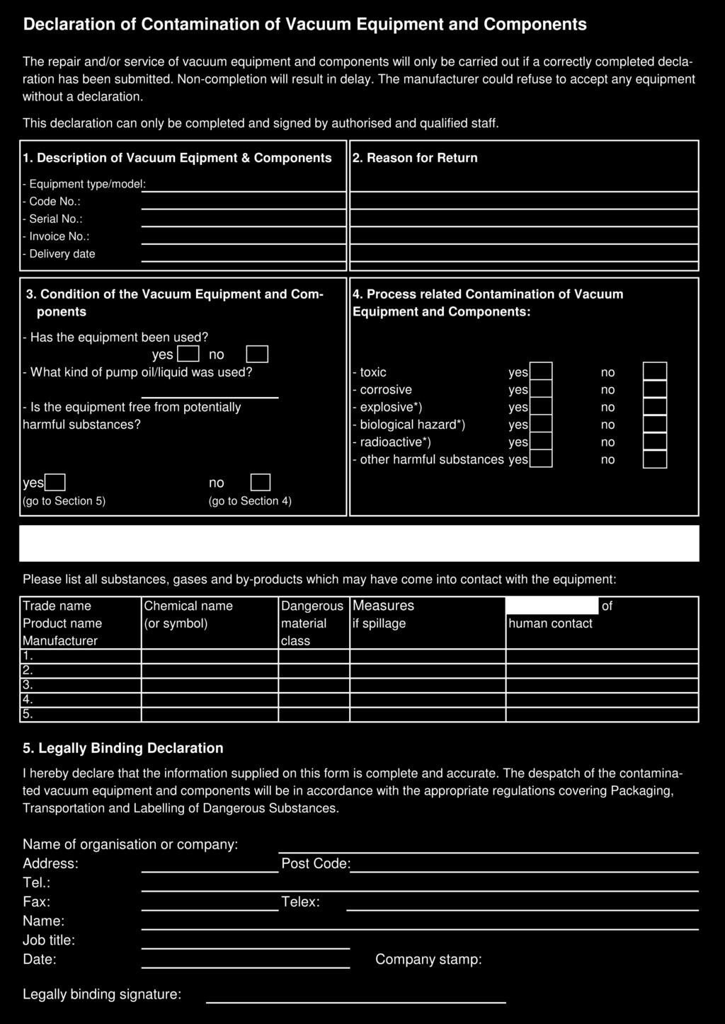
3 0. Table of Contents 4. SPECIFICATIONS AND OPTIONS Technical data of Standard Version Technical data of Compact Version Analog Output Signal Pin Assignment of the Gauge Head Accessories Additional Manuals 30 Appendix 1 Return of Vacuum Equipment 31 Declaration of Contamination Form Appendix 2 CE-Declaration of Conformity 09/2004 2
4 0. Table of Contents 0.1 List of Figures Figure 1 Correction curves for the Pirani gauge 8 Figure 2 Front view of the Controller 9 Figure 3 Rear view of the Controller after removing the rear cover 9 Figure 4 Pin assignment of the Sub-D connector Power supply/signal 10 Figure 5 Function of Control 1 and Control 2 10 Figure 6 Jumpers for operation parameters (rear cover of the Controller removed) 11 Figure 7 Set-up of the COM interface 15 Figure 8 Program window - Monitor 16 Figure 9 Adjustment via analog control inputs 24 Figure 10 Dimensions of Standard Version (data in mm) 26 Figure 11 Schematic of Standard Version 26 Figure 12 Dimensions of Compact Version (data in mm) 28 Figure 13 Schematic of Compact Version 28 Figure 14 Analog output signal 29 Figure 15 Pin assignment of the Gauge Head List of Tables Table 1 Correction factors for the ion gauge 8 Table 2 Function of Control 1 and Control 2 10 Table 3 Output level of set point output 11 Table 4 Operation parameters of the Controller defined by the jumper positions 11 Table 5 Important readout and write commands 12 Table 6 Control bits of 13 Table 7 Status bits of 14 Table 8 Conversion of pressure values to input values in hexadecimal notation for set point definition /2004
5 1. Safety 1.1 Basic Safety Instructions All servicing and repairing works must be done by qualified personnel. Follow the instructions for servicing and repairing works. Observe all safety regulations (EN 61010). 1.2 Signs Qualified personnel only! Attention, danger! Attention, electric danger! 1.3 General Regulations and Warranty For proper operation of the device, we assume a warranty of one year. During this time, material and manufacturing defects will be repaired free of charge. Normal wear and malfunction due to improper use (eg including contamination of the gauge head) are not covered under warranty. The manufacturer makes no warranty, if the user or third persons have made changes to the device, which go beyond the works mentioned in the related manual. Return of the device has to be in the original packaging and at the expense of the customer. We reserve the decision on replacement or repair after inspection of the device in our house. Prerequisite for warranty claims is the return of the device in the original manufacturer s packaging! Attach with a return the completed Declaration of Contamination Form. 09/2004 4
6 2. Description 2.1 In General The Wide Range Manometer provides pressure measurement in the range from to mbar (760 to Torr) by combining a heat loss sensor based on the Pirani principle with a Bayard-Alpert ion gauge. The system is available as Standard Version or Compact Version. These versions vary in the following features: Vacuum flange of gauge head Design of gauge head Emission current of Bayard-Alpert-System Dimensions and weight More technical data of both versions are described in the section Technical data. Both versions are available with Profibus-DP fieldbus as an option. Each gauge is mounted into a tube and is additionally protected by a grid. Both tube and grid offer the following advantages: Mechanical protection of the gauge Constant electrical ambient potential, i.e. defined sensitivity High measuring accuracy and reproducibility of results Protection against electromagnetic fields The Wide Range Manometer switches from Pirani gauge to the Bayard-Alpert ion gauge at a pressure of mbar. At a pressure of mbar, the switches from Bayard-Alpert ion gauge to Pirani gauge. Please note this for process control. The Controller is directly mounted onto the gauge head. The power supply of the controller is 24 V DC / 1.5 A. The output signal is an analog signal between 0 V and 10 V (logarithmic with V per decade). The pressure value is calibrated for nitrogen and must be corrected by a calibration factor for other gases. Explosion hazard! Do not use the Wide Range Manometer to measure the pressure of explosive or combustible gases or gas mixtures. The ion gauge filaments operate at high temperature. Inside the manometer, voltages up to 400 V at 20 ma are generated. 5 09/2004
7 2. Description 2.2 Measuring Principle The Wide Range Manometer combines a Pirani gauge with a Bayard-Alpert ion gauge. The Pirani gauge is based on the principle that the heat loss of a thin wire, heated by an electrical current, depends on the pressure and the gas type. Different processes contribute to the heat loss: a) Heat conductance of the gas b) Convection of the gas c) Heat radiation d) Heat conduction into the wire connection Items c) and d) are disturbance variables which limit the measuring range of the Pirani gauge towards low pressure. To keep these variables as small and constant as possible, a very thin wire is used as sensor and the operating temperature of the wire is kept constant. For this purpose, a Wheatstone bridge measures the resistance of the wire, and its resistance is kept constant by a control circuit. The power supplied to the wire is measured. Below 10 mbar, the pressure dependency of the heat loss is predominated by the heat conduction through the gas. Above 100 mbar, convection of the gas is the most important process. Measured results are mainly falsified by dirt deposition on the Pirani wire and by an increase of the ambient temperature which both modify the heat loss of the Pirani wire. Shocks and vibrations lead to an increased heat emission of the Pirani wire and thus to the display of an apparently higher pressure. The Bayard-Alpert ion gauge uses the ionisation of the gas atoms or molecules by electrons. Electrons are emitted from a heated cathode and are accelerated by the grid. Inside the grid, the electrons ionise the gas. The ions are collected and measured as a collector current. The collector current is proportional to the gas pressure over a wide range. But due to the different ionisation probability of atoms and molecules the collector current is dependent on the gas type. Towards low pressure, the measuring range is restricted by the X-ray limit and by gas emission from the tube itself. For gauges with a geometry used for the Wide Range Manometer, this limit is typically several mbar. The high pressure limit is set to 10-1 mbar to protect the gauge against burning out. At this pressure, the manometer switches to the Pirani gauge. The accuracy of the measured values of the Pirani gauge will deviate from that specification for a short period until the thermal equilibrium has been reached. This is due to the gauge warming as a result of the cathode heating. A blocking period protects the ion gauge! When the Gauge is switched automatically from the ion gauge to the Pirani gauge by an increase of the pressure, the ion gauge can be reactivated by lowering the pressure to mbar and after a blocking period of 5 sec. 09/2004 6
8 2. Description Too high or fluctuating pressure values from the ion gauge can be caused by contamination of the gauge head (increased outgassing possible). In this case, it is recommended to heat up and clean the gauge by degassing under high vacuum ( mbar or less) by means of electron bombardment. The pressure reading during degassing serves for information about the cleaning process only and does meet the accuracy specification of the Gauge. By degassing the gauge contaminants are largely removed. If electrons or ions generated by other processes in the vacuum system reach the ion collector or if the electrons generate further ions, the pressure readings can be erroneous. The use of a baffle to protect the gauge head can reduce this effect. Strong magnetic fields, such as those generated by ion getter pumps, result in diffraction of electron trajectories and thus possibly in measuring errors. In this case, it is useful to increase the distance between the Gauge and the magnet or to shield the gauge. 7 09/2004
9 2. Description 2.3 Correction Factors of Different Gases The measuring principles applied by the Wide Range Manometer are gas-type dependent. Consequently, the composition of the gas has to be determined to extract the real pressure from the displayed pressure value Correction Factors for the Ion Gauge For the Bayard-Alpert ion gauge, the real pressure can be calculated by multiplying the displayed pressure value by a correction factor if the composition of the gas is known. The correction factors of two frequently used gases: Helium and Argon: have been determined for the Gauge (Table 1). Please contact VACOM GmbH if you need correction factors of further gases. Gas Table 1: Correction factors for the ion gauge Correction factor Helium (He) 5.0 Argon (Ar) 0.7 Nitrogen (N 2 ) 1.0 Air Correction Curve for Pirani Gauge For Pirani gauges, it is principally impossible to determine correction factors that are independent of pressure. The correction can be performed by means of the correction curves as shown in Figure 1. Figure 1: Correction curves for the Pirani gauge 09/2004 8
. Figure 2: Front view of the Controller 1. Plug connection for the gauge head 2. 2 guide holes 3.")
 4. Jumpers of parameter setting 5. Fine adjustment of sensitivity 6. Indicating LED (green) of Profibus interface (option) 7.")
10 2. Description 2.4 The Controller The controller is intended for use in dry areas (protection class IP 40). The Controller is plugged onto the gauge head. A screw collar ring tightens the plug connection (Figure 2 / Figure 3). Figure 2: Front view of the Controller 1. Plug connection for the gauge head 2. 2 guide holes connectors (female) Figure 3: Rear view of the Controller after removing the rear cover 1. Profibus Interface (option) 2. Connector for power supply, signal, and RS 232 interface 3. Address switches of Profibus interface (option) 4. Jumpers of parameter setting 5. Fine adjustment of sensitivity 6. Indicating LED (green) of Profibus interface (option) 7. Indicating LED of operation and error mode (red, green, orange) 9 09/2004
11 2. Description The 15 pin Sub-D connector on the rear of the Controller is used for the power supply of the Wide Range Manometer and for data transmission (Figure 3 / Figure 4). The LED indicates the operation mode of the Gauge = PIN 1 Input External control ON/OFF, high level 24V is required to control the via PIN 4, 5, 6 = PIN 2 Output Send TxD / RS 232 = PIN 3 Input Read RxD / RS 232 = PIN 4 Input Control 1 (in combination with PIN 1 and PIN 5 for adjustment of the Pirani gauge), ( Table 2) = PIN 5 Input Control 2 (in combination with PIN 1 and PIN 4 for adjustment of the Pirani gauge), ( Table 2) = PIN 6 Input Start of degassing, with high level 24 V = PIN 7 Input Power supply 24 V DC = PIN 8 Input Power supply 24 V DC = PIN 9 Output Status of degassing or of set point ( Table 3) = PIN 10 Output Selected filament (high level 24 V DC = filament 1 low level 0 V DC = filament 2) = PIN 11 Input Ground connection = PIN 12 Input Ground connection = PIN 13 Output Reserved = PIN 14 Output Output of pressure value (analog output signal, logarithmic) = PIN 15 Output Analog ground Figure 4: Pin assignment of the Sub-D connector Power supply/signal (male) External control (1 = high) Control 1 Control 2 Function Pirani gauge only Auto mode Adjustment of Pirani gauge to atmosphere Adjustment of Pirani gauge to vacuum Table 2: Function of Control 1 and Control 2 Figure 5: Function of Control 1 and Control 2 09/
12 2. Description Function Set point, normal Set point, inverted On 1 0 Off 0 1 Table 3: Output level of set point output The LED Mode indicates the following operation modes of the Gauge: Red Green Orange-green blinking Red blinking Green blinking (frequency of 2 Hz) Pirani gauge working ion gauge working both filaments of ion gauge defective or safety turn-off (high pressure) Pirani gauge defective degassing The set-up of the operation parameters (Table 4) is defined by the position of the jumpers J1 to J4 (Figure 6) of the Controller. Before changing the jumper position, the power supply of the Controller has to be turned off and the rear cover of the controller has to be removed. Any change of the jumper position is valid from the next turn-on. Figure 6: Jumpers for operation parameters (rear cover of the Controller removed) Jumper Function OFF ON J1 J2 J3 J4 Transistor output of degas status or set point Transistor output of set point normal or inverted Automatic change of emission current of ion gauge for low pressure suppressed Baud rate of Controller Status of degassing (factory-installed) Normal set point (factory-installed) Automatic change of emission current at a pressure between 10-5 and 10-6 mbar (factory-installed) bauds per sec (factory-installed) Set point Inverted set point Low emission current only (for pressure higher than 10-6 mbar) bauds per sec Table 4: Operation parameters of the Controller defined by the jumper positions 11 09/2004
13 2. Description 2.5 Serial Interface RS 232 The Wide Range Manometer can be monitored via a serial interface RS 232 that is integrated within a 15 pins Sub-D connector (Figure 4). For PC application, an adapter with separate output of the serial interface is optionally available Parameters String: 8 data bits; 1 stop bit; no parity; no protocol Baud rate: or bauds per sec End of string indicated by <CR> Commands Many functions of the Wide Range Manometer can be directly transmitted as RS 232 commands. Command RV RS RP RA Function Readout of pressure Readout of status bits Readout of low (on) and high (off) set points: logarithmic output with hexadecimal notation. Conversion to pressure value in mbar: p = 10 (Output/ ) (or refer to Table 8) Readout of jumper positions RT Readout of operation time of filament 1 and filament 2 in hours ( ) RB SD SC**** SP**** **** SA**** SX1 SX0 Readout of status bits SPC 3 (Profibus interface only) Start of degassing (turns off automatically after 2 min) Setting of control bits Setting of low (ON) and high (OFF) set points: logarithmic input with hexadecimal notation. Conversion of pressure in mbar to input: Input = log (pressure) (or refer to Table 8) Overwriting jumpers (all jumpers have to be set to 0 or 1, but only the parameters of jumpers J1 to J3 are written, baud rate can only be modified by hardware setting of jumper J4) Start of repetitive output of pressure value and service data every 500 ms Stop of repetitive output of pressure value and service data Table 5: Important readout and write commands Readout of pressure RV The actual pressure can be read out by entering RV <CR>. The output string contains the information about the measuring mode and the pressure value: Status: P = Pirani gauge D = Degas I1 = Filament 1 of ion gauge E = Error I2 = Filament 2 of ion gauge Pressure: 0.00E±00 = measured pressure value in mbar For example: I2_8.21E-06 (ion gauge), P_5.3E+01 (Pirani gauge) 09/
14 2. Description Definition of control bits: SC Bit Active Name Description 0 1 AUTORANGE Change between Pirani and ion gauge automatically (condition factory-installed) 1 1 PIRANI Only valid for AUTORANGE = 0: Pirani gauge only, ion gauge is deactivated 2 1 IG Only valid for AUTORANGE = 0: ion gauge only, Pirani gauge is activated only in case of safety turn-off of the ion gauge 3 1 AUTOFIL Change between filament 1 and filament 2 automatically (condition factory-installed) 4 1 FIL1 5 1 FIL2 Only valid for AUTOFIL = 0: filament 1 is selected, filament 2 is deactivated Setting is only possible if Pirani gauge is activated Only valid for AUTOFIL = 0: filament 2 is selected, filament 1 is deactivated Setting is only possible if Pirani gauge is activated 6 1 DEGAS Start of degassing, automatically stopped after 2 min 7 1 E_STROM Selection of low emission current 8 1 SP_MAN Only valid for closed jumper J1: output level of PIN 9 can be set manually 9 1 SP_OUT Only valid for closed jumper J1 and SP_MAN = 1: setting of output level of PIN SP_AUTO Only valid for closed jumper J1 and SP_MAN = 0: output level of PIN 9 is pressure dependent, pressure condition is defined by the set point function 11 1 EXT_ENABLE External control (pins 4, 5, 6) enabled (1) or disabled (0) 12 1 R_ERROR Setting is only possible if PIRANI = 1 and AUTORANGE = 0: reset of error bit of ion gauge 13 1 VAK Zero-adjustment of Pirani gauge at vacuum pressure 14 1 ATM Adjustment of Pirani gauge to atmospheric pressure 15 1 n.a. Not available Table 6: Control bits of Examples The Wide Range Manometer selects the Pirani or ion gauge and the filaments of the ion gauge automatically: `SC_0009`<CR> `SC_0049`<CR> `SC_0021`<CR> AUTORANGE Bit 0 1 AUTORANGE Bit 0 1 AUTORANGE Bit 0 1 PIRANI Bit 1 0 PIRANI Bit 1 0 PIRANI Bit IG Bit 2 0 IG Bit 2 0 IG Bit 2 0 AUTOFIL Bit 3 1 AUTOFIL Bit 3 1 AUTOFIL Bit 3 0 FIL1 Bit 4 0 FIL1 Bit 4 0 FIL1 Bit 4 0 FIL2 Bit 5 0 FIL2 Bit 5 0 FIL2 Bit DEGAS Bit 6 0 DEGAS Bit 6 1 DEGAS Bit 6 0 E_STROM Bit 7 0 E_STROM Bit 7 0 E_STROM Bit 7 0 SP_MAN Bit 8 0 SP_MAN Bit 8 0 SP_MAN Bit 8 0 SP_OUT Bit 9 0 SP_OUT Bit 9 0 SP_OUT Bit SP_AUTO Bit 10 0 SP_AUTO Bit 10 0 SP_AUTO Bit 10 0 EXT_ENABLE Bit 11 0 EXT_ENABLE Bit 11 0 EXT_ENABLE Bit 11 0 R_ERROR Bit 12 0 R_ERROR Bit 12 0 R_ERROR Bit 12 0 VAK Bit 13 0 VAK Bit 13 0 VAK Bit ATM Bit 14 0 ATM Bit 14 0 ATM Bit 14 0 n. a. Bit 15 0 n. a. Bit 15 0 n. a. Bit /2004
15 2. Description Definition of status bits: RS Bit aktiv Name Description 0 1 AUTORANGE Mode of auto range activated 1 1 PIRANI Only Pirani gauge is activated, read out of pressure 2 1 IG Only ion gauge is activated, read out of pressure 3 1 AUTOFIL Mode of AUTOFIL is activated 4 1 FIL1 Filament 1 is selected 5 1 FIL2 Filament 2 is selected 6 1 DEGAS Degas activated 7 1 E_STROM Low emission current is selected 8 1 SP_MAN Output level of PIN 9 can be set manually 9 1 SP_OUT Output level of PIN 9 (1 indicates 24V) 10 1 SP_AUTO Set point function or output of degas status activated 11 1 EXT_ENABLE External control enabled 12 1 R_ERROR Error bit of ion gauge has been reset 13 1 VAK Zero-adjustment of Pirani gauge at vacuum pressure activated 14 1 ATM Adjustment of Pirani gauge to atmospheric pressure activated 15 1 LEBENSBIT Test bit of sent every 500 msec Table 7: Status bits of Example The dialogue is as follows if the Wide Range Manometer is operated in following mode: auto range, ion gauge is activated, automatic selection of filaments, filament 1 is activated. Command `RS`<CR> inquires the status. Generated reply will be: 001D. 09/

16 2. Description The Service Program The Service Program is supplied for simple tests and service of the Wide Range Manometer. It can be downloaded free of charge from The service programme supports all RS 232 commands of Section 2.5. For running the System with a PC, the input of the power supply and the RS 232 interface have to be separated. This can be easily done by taking the optionally available PC adapter and a modem cable Set-up of the PC interface After having installed the Service Programme atmion-4.exe, the programme starts with the window COM-Anschluss-Einstellungen. The interface of the PC (Figure 7) has to be selected and the baud rate has to be set to the baud rate of the Controller (Section 2.5.1). OK continues the programme. It opens the main window ATMION-Monitor (Figure 8). Figure 7: Set-up of the COM interface Operation of the Service Program On the main window Monitor für ATMION (Figure 8) of the service programme commands can be entered and the status of the Wide Range Manometer is shown. Section Steuern ATMION 13 important control bits (Table 6) can be activated by mouse click. The software prevents impossible combinations. A click on Steuerwort senden sends the command to the Controller. Section Status ATMION All 16 status bits (Table 7) are shown. Grey letters indicate deactivation, black letters indicate active states. The display of the test bit of the is blinking green while data transmission. The measured pressure is shown in the line indicated Druck /2004

17 2. Description Section Befehl Read and write commands (Table 5) can be entered here. A mouse click on Senden sends each command to the Controller. Section Monitor Senden This section shows all sent commands and sent control bits. Section Monitor Empfang This section shows the data resent by the Controller. A click on Start starts the data transmission every 500 ms. These data are stored in file C:\atmionlog.txt and can be used for further evaluation. A click on Stop stops the data output. Figure 8: Program window : Monitor It is possible to return to interface page COM-Anschluss-Einstellungen by mouse click on Schnittstelle ( Section ). 09/
18 3. Assembly and Operation 3.1 Visual Control The Gauge is mounted inside a stainless steel tube. Additionally, the flange of the tube is covered by a grid to protect the gauge. Nevertheless, handle it with care. Avoid touching all components intended for the vacuum area. All gauges and controllers are individually inspected and carefully packed before delivery. After unpacking, check the Wide Range Manometer visually for mechanical damages caused by transportation. If you find any damage, please contact VACOM GmbH immediately. Complaints submitted after putting the manometer into operation or later than 5 working days after receipt cannot be accepted. 3.2 Assembly Usually, the Gauge and the Controller are jointed together when they are delivered. The Wide Range Manometer can be mounted directly to the vacuum system in any position. Otherwise, the gauge head can be mounted to the vacuum system. Subsequently, plug the controller and tighten it with the screw collar ring. Do not mount the gauge very close to the venting valve. Despite automatic cathode switchoff, the cathode might be damaged when the vacuum system is vented. The Wide Range Manometer can be monitored by: The optionally available Display Unit and successors MVC3-A or ATMIGRAF PC via serial interface and any power supply 24 V DC / 1.5 A (power supply and PC adaptor with separate serial interface RS232, 9 pin Sub-D connector are optionally available) System control (24 V DC) and any power supply 24 V DC / 1.5 A 3.3 Set Point Function The Wide Range Manometer provides one internal set point function that is activated by the jumper set-up and is adjustable by the serial interface. Jumper J2 activates the set point function and J3 defines if the set point is operated as normal or as inverted set point (Figure 6 / Table 4). The pressure values have to be defined via serial interface (Section 2.5 / Table 5). Table 8 shows the conversion between pressure value and input value. Alternatively, the Display Unit supplies (Manual Display Unit) up to 4 set point functions /2004
19 3. Assembly and Operation Pressure in mbar Conversion of pressure to input: Input = log (Pressure) Input value in hexadecimal notation for definition of set point 1,00E F000 5,00E EB2F 1,00E E000 5,00E DB2F 1,00E D000 5,00E CB2F 1,00E C000 5,00E BB2F 1,00E B000 5,00E AB2F 1,00E A000 5,00E B2F 1,00E ,00E B2F 1,00E ,00E B2F 1,00E ,00E B2F 1,00E ,00E B2F 1,00E ,00E B2F 1,00E ,00E B2F 1,00E Table 8: Conversion of pressure values to input values in hexadecimal notation for set point definition 3.4 Cleaning of the Gauge Head Contamination of the ion gauge can falsify the displayed pressure value. In that case, it is recommended to clean the ion gauge by degassing. The degassing cleans the ion gauge by electron bombardment. The procedure can be carried out at a pressure lower than 10-4 mbar. The frequency of the degassing depends on the degree of contamination during the process and the operation time. It is suggested to degas the ion gauge regularly every 1 to 4 weeks. The degassing can be started by: The control input PIN 6 of the 15 pin Sub-D connector (Figure 4) The function DEGAS of the Display Unit (Manual Display Unit) Input of Degas or command SD at the Service Programme (Section 2.5.3) Input of command SD at the serial interface (Table 5) The degassing ends automatically after 2 min or in case of a too high pressure. The degassing can be repeated if the time has not been long enough. 09/
20 3. Assembly and Operation 3.5 Bake out of the Head The maximum baking temperature is different for the Standard and Compact Version of the Gauge. The following values indicate the maximum temperature allowed on the flange of the gauge tube (flange with the protection grid for Standard Version): Gauge Standard Version max. 250 C at the flange Gauge Compact Version max. 180 C at the flange The Gauge Connector of the Standard Gauge, the pin connector of the Compact Gauge and the Controller contain electronic devices that are not allowed to exceed temperatures above 60 C! For saving the electronic devices, the Controller and the Gauge Connector of the Standard Gauge can be removed by the following procedure: (Figures 11 and 13) Unplug the Controller Open the screw collar ring which tightens the gauge head and the controller Extract the gauge out of the controller Do not twist the gauge head. The pins and electronics could get damaged. Gauge Standard Version: open the three screws (M3) and unplug the gauge head connector. Assembly after baking in opposite order. 3.6 Filaments of the Ion Gauge The Gauge has two filaments for insuring a longer lifetime of the ion gauge. It is factory-installed that filament 1 is selected automatically. Filament 2 is only taken automatically if filament 1 has burned out. The sequence can only be changed by deactivating the automatic selection and by choosing filament 1 or 2 manually (Figure 4 / Table 6). However, please pay attention that the automatic selection of the second filament is not activated in the case of burn-out. The filament has to be selected manually again /2004
21 3. Assembly and Operation Display and selection of the filaments: FIL 1 or FIL 2 at Display Unit (Manual Display Unit) Filament 1 or Filament 2 and I1 or I2 at the Service Programme (Section 2.5.3) Output signal PIN 10 of the 15 pin Sub-D connector (Figure 4) At the Standard Version of the Gauge, it is possible to replace the filaments. At the Compact Version of the Gauge, the complete gauge head has to be replaced when both filaments have burned out. You should ask for replacement filaments or replacement gauge when the first filament is burned out. 3.7 Exchange of Filaments of Standard Gauge Heads At the Standard Version of the Gauge, it is possible to replace the filaments. If the customer replaces the filament himself, VACOM GmbH cannot warrant the original accuracy of the ion gauge. If the original accuracy is required, the Gauge should be replaced or be repaired by VACOM GmbH. The replacement of the gauge head is described in Section 3.8. Exchange of filaments: Unplug the controller and remove the gauge from the vacuum system Open the screw collar ring which tightens the gauge and the controller (Figure 11) Extract the gauge out of the controller Do not twist the gauge head. The pins and electronics could get damaged. Open the three screws (M3) and unplug the Gauge Connector Put the gauge on flat ground with the flange on bottom and the pin connector on top Open the screws (M6) which tighten the gauge tube Carefully remove the gauge tube and the copper seal straight along the axis of the gauge Do not tilt the gauge tube. Otherwise the ion gauge or the Pirani wire can be destroyed. 09/
22 3. Assembly and Operation Put the gauge on flat ground with the pin connector on bottom Open the screws of the barrel connector and pull out the burned filaments (tweezers!) Take the new filaments out of their case with a pair of tweezers Insert the new filaments into the barrel connector and tighten them with new screws Remove the stabilising wire that connects the filaments just above the screw (pincers!) Take a new copper seal Carefully insert the gauge into the gauge tube Tighten the gauge tube with the screws (M6) Plug the Gauge Connector and tighten it with the screws (M3) Insert the gauge into the controller (see the guiding mark!) Tighten the screw collar ring Attach the Wide Range Manometer to the vacuum system. 3.8 Exchange of the Gauge Head The exchange of the Gauge (Standard and Compact Version) is carried out by the following procedure: Unplug the controller and remove the gauge from the vacuum system Open the screw collar ring which tightens the gauge and the controller (Figure 11 or 13) Extract the gauge out of the controller Do not twist the gauge head. The pins and electronics could get damaged. If the replacement gauge is an Gauge with increased accuracy: Find the value for fine adjustment of sensitivity on the Gauge and remember it Insert the new gauge into the controller (see the guiding mark!) Tighten the screw collar ring Attach the Wide Range Manometer to the vacuum system Find the value for fine adjustment of sensitivity on the Gauge Open the rear cover of the Controller Find the fine adjustment (Figure 3) of the sensitivity - turn it to position 7 in case of Gauge with standard accuracy - turn it to the indicated position in case of Gauge with increased accuracy Close the controller Complete the assembly After exchanging the Gauge, you should adjust the Pirani gauge to ensure proper operation (Section 3.9) /2004
23 3. Assembly and Operation 3.9 Adjustment of the Pirani Gauge The Gauge is delivered adjusted. However, it is necessary to re-adjust the Pirani gauge if it is displaced at transport, after longer operation, or after exchange of the Gauge. Depending on your equipment, different adjustment procedures are possible. However, it is common for all procedures that the Pirani gauge is adjusted to atmospheric pressure and to the zero value at a pressure below 10-4 mbar Adjustment via Display Unit Adjustment of the upper limit of the Pirani gauge at 1,000 mbar (atmospheric pressure) The display device is switched on and in the measuring mode. Press key OK for 2 sec. The displayed pressure value starts blinking. Press cursor key p. The upper Pirani limit will automatically be readjusted. This is indicated by displaying n n n for 5 seconds. Now the measuring system and the display device have re-entered the normal display mode. Adjustment of the zero point of the Pirani gauge at a pressure of 10-4 mbar The display device is switched on and in the measuring mode. Press key OK for 2 sec. The displayed pressure value starts blinking. Press cursor key q. The Pirani zero point will automatically be readjusted. This is indicated by displaying u u u for approx. 5 seconds. Now the measuring system and the display device have re-entered the normal display mode. The upper Pirani limit adjustment is performed at atmospheric pressure (1,000 mbar), the zero point adjustment is done at a pressure of p < 10-4 mbar. The upper limit adjustment and the zero point adjustment are procedures independent from each other. Therefore, the two steps can be performed at different points of time Adjustment via Serial Interface RS 232 or Profibus Interface The adjustment via serial interface RS 232 or Profibus interface can be done by entering the corresponding control bits (Section 2.5 / Table 6 and Manual Profibus Interface). Adjustment of Pirani gauge to 1000 mbar (atmospheric pressure) Vent gauge (1000 mbar) Input of `SC_0002` The Gauge works in the Pirani mode and measures the actual pressure value Input of `SC_4002` Automatic correction of the displayed value Input of `SC_0002` The Gauge works in the Pirani mode, the corrected pressure value is stored 09/
24 3. Assembly and Operation Zero adjustment of Pirani gauge at a pressure below 10-4 mbar Evacuate the Gauge to a pressure below 10-4 mbar Input of `SC_0002` The Gauge works in the Pirani mode and measures the actual pressure value Input of `SC_2002` The zero value of the Pirani gauge is corrected automatically Input of `SC_0002` The Gauge works in the Pirani mode, the correcte pressure value is stored Input of `SC_0009` The Gauge switches automatically to the ion gauge (Mode AUTORANGE and AUTOFIL) Adjustment via control input or external system control The adjustment via external control (24 V DC) uses the input PIN 4 and PIN 5 of the 15 pin Sub-D connector (Figure 4). To enable these inputs, the input PIN 1 must be set to high level 24 V DC. The following procedure has to be done, Figure 9 shows schematically the whole procedure: Adjustment of Pirani gauge to 1000 mbar (atmospheric pressure) Vent gauge (1000 mbar) Connect PIN 1 with PIN 7 or 8 (power supply 24 V DC) The inputs Control 1 and Control 2 are enabled Connect PIN 4 (Control 1) with PIN 7 or 8 (power supply 24 V DC) The Gauge works in the Pirani mode and measures the actual pressure value Additionally connect PIN 5 (Control 2) with PIN 7 or 8 Automatic correction of the displayed value Disconnect PIN 5 (Control 2) from PIN 7 and 8 The Gauge works in the Pirani mode, the corrected pressure value is stored PIN 4 (Control 1) remains connected with PIN 7 or 8 (power supply 24 V DC) Zero adjustment of Pirani gauge at a pressure below 10-4 mbar Evacuate the Gauge to a pressure below 10-4 mbar PIN 4 (Control 1) still remains connected with PIN 7 or 8 (power supply 24 V DC) The Gauge works in the Pirani mode and measures the actual pressure value Disconnect PIN 4 (Control 1) from PIN 7 and 8 Connect PIN 5 (Control 2) with PIN 7 or 8 (power supply 24 V DC) The zero value of the Pirani gauge is corrected automatically Disconnect PIN 5 (Control 2) from PIN 7 and /2004
25 3. Assembly and Operation Connect PIN 4 (Control 1) with PIN 7 or 8 (power supply 24 V DC) The Gauge works in the Pirani mode, the corrected pressure value is stored Disconnect PIN 4 (Control 1) from PIN 7 and 8 The Gauge switches automatically to the ion gauge Disconnect PIN 1 from PIN 7 and 8 The inputs Control 1 and Control 2 are disabled. Extern enable 24 V 0 V Controlled by RS232 Extern enable on Pirani only; monitoring of actual athmosphere pressure automatically correction of athmosphere value Pirani only; corrected value is stored Pirani only; monitoring of actual pressure value automatically correction of zero point Pirani only; corrected value is stored ATMION switches to ionisation range automatically Extern enable off; controlled by RS V Control 1 0 V 24 V Control 2 0 V t > 2 s for every step Athmosphere pressure 1000 mbar pump to pressure < 10-4 mbar Pressure < 10-4 mbar Figure 9: Adjustment via analog control inputs 09/
26 4. Specifications and Options 4.1 Technical data of Standard Version Operating voltage: 24 V DC ± 10 % Power Consumption: Normal operation: max. 10 W (during switch on of ionisation system max. 15 W) Degas: max. 36 W Current consumption: Normal operation: max. 0.4 A (during switch on of ionisation system max. 0.6 A) Degas: max. 0.9 A Interface: Serial interface RS 232 Profibus-DP (optional) Analog control: Output signal: Set point function: Input / Output 24 V DC V logarithmic linear with 0,625 V per decade Algorithm: U = 0,625 lg (p / mbar) 1 set point (Transistor output, max. 24 V DC, max. 0.2 A) Ambient temperature: 40 C Cathode material: Emission current: Vacuum flanges : Measuring range: Measuring accuracy: Bake out temperature: Wight: max. Yttria coated Iridium Measuring process: 2 µa (low), 2 ma (high); Degas: 20 ma Thresholds for automatic switching during the measuring process: low -> high: p = mbar high -> low: p = mbar DN40CF mbar ± 25 % ( mbar) ± 10 % ( mbar) max. 250 C at flange 1.6 kg Dimensions: Width: 105 mm (IP40) 113 mm (IP65) Height: 70 mm (IP40) 76 mm (IP65) Depth: 191 mm (IP40) 194 mm (IP65) 25 09/2004
 Figure 11: Schematic of Standard Version A B C D E F G H Protective gauge tube with flange DN40CF Flange connection with copper gasket and six srews M6 Copper gasket 3 setscrews M2")
27 4. Specifications and Options DN35CF 70 (IP40) 76 (IP65) Bus Connector Bus active Power supply / Signal Mode (IP40) 194 (IP65) 105 (IP40) 113 (IP65) Figure 10: Dimensions of Standard Version (data in mm) Figure 11: Schematic of Standard Version A B C D E F G H Protective gauge tube with flange DN40CF Flange connection with copper gasket and six srews M6 Copper gasket 3 setscrews M2 Connection between gauge head and adaptor Adaptor with screw collar ring and printed circuit board Connection between Adaptor and Controller Controller 09/
28 4. Specifications and Options 4.2 Technical data of Compact Version Operating voltage: 24 V DC ± 10 % Power Consumption: Normal operation: max. 10 W (during switch on of ionisation system max. 15 W) Degas: max. 36 W Current consumption: Normal operation: max. 0.4 A (during switch on of ionisation system max. 0.6 A) Degas: max. 0.9 A Interface: Serial interface RS 232 Profibus-DP (optional) Analog control: Output signal: Set point function: Input / Output 24 V DC V logarithmic linear with 0,625 V per decade Algorithm: U = 0,625 lg (p / mbar) 1 set point (Transistor output, max. 24 V DC, max. 0.2 A) Ambient temperature: 40 C Cathode material: Emission current: Vacuum flanges: Measuring range: Measuring accuracy: Bake out temperature: Wight: max. Yttria coated Iridium Measuring process: 2 µa (low), 2 ma (high); Degas: 20 ma Thresholds for automatic switching during the measuring process: low -> high: p = mbar high -> low: p = mbar DN25KF, DN40CF mbar ± 25 % ( mbar) ± 10 % ( mbar) max. 180 C at flange 1.0 kg Dimensions: Width: 105 mm (IP40) 113 mm (IP65) Height: 70 mm (IP40) 76 mm (IP65) Depth: 147 mm (IP40) 150 mm (IP65) 27 09/2004
 Figure 13: Schematic of Compact Version A B C D Gauge head with vacuum flange and printed circuit board Screw collar ring Connection between gauge head and Controller Controller 09/2004")
29 4. Specifications and Options DN25KF 70 (IP40) 76 (IP65) Bus Connector Bus active Power supply / Signal Mode (IP40) 150 (IP65) 105 (IP40) 113 (IP65) Figure 12: Dimensions of Compact Version (data in mm) Figure 13: Schematic of Compact Version A B C D Gauge head with vacuum flange and printed circuit board Screw collar ring Connection between gauge head and Controller Controller 09/


30 4. Specifications and Options 4.3 Analog Output Signal 1E+04 1E+03 1E+02 1E+01 1E+00 1E-01 1E-02 1E-03 1E-04 1E-05 1E-06 1E-07 1E-08 1E-09 1E-10 1E-11 1E-12 Figure 14: Analog output signal 4.4 Pin Assignment of the Gauge Head Figure 15: Pin assignment of the Gauge Head PIN 1 Pirani wire PIN 2 Pirani wire PIN 3 Anode grid PIN 4 Collector PIN 5 Anode grid PIN 6 Pirani input PIN 7 Pirani output PIN 8 Filament 1 PIN 9 Filament common PIN 10 Filament /2004
31 4. Specifications and Options 4.5 Accessories Order number ATD1 / ATD2* ATDP1 / ATDP2* AG* AGPC* MVC3-A0 Designation Display and control unit for one ATMION-System (115 V AC / 230 V AC) Display and control unit for one ATMION-System and one additional fore line pressure sensor (115 V AC / 230 V AC) Display unit for one ATMION-System (24 V DC) Display unit for one ATMION-System with serial interface (24 V DC) Display and control unit for one ( VAC) MVC-AM Display and control unit for one and two low vacuum gauges ( ATPC AT24E ATL3 ATL5 ATLPC5 * no longer available VAC) 4.6 Additional Manuals Interface adapter (RS232) Power supply 24 V DC Measuring line between ATMION-System and Display unit, lenght 3 m Measuring line between ATMION-System and Display unit, lenght 5 m Modem line to PC-connection, lenght 5 m Manual of Profibus-DP Standard and Compact Version Manual of Display Unit 09/
32 Return of Vacuum Equipment: Procedure Introduction Before you return your equipment you must warn your supplier if the substances you used (and produced) in the equipment can be dangerous. You must do this to comply with health and safety at work laws. You must complete the Declaration of Contamination on the next page and send it to your supplier before you dispatch the equipment. If you do not, your supplier will assume that the equipment is dangerous and he will refuse to accept it. If the Declaration is not completed correctly, there may be a delay in processing your equipment. Guidelines Take note of the following guidelines: Your equipment is uncontaminated if it has not been used or if it has only been used with substances that are not dangerous. Your equipment is contaminated if it has been used with any dangerous substances. If your equipment has been used with radioactive substances, you must decontaminate it before you return it to your supplier. You must send independent proof of decontamination (for example a certificate of analysis) to your supplier with the Declaration of Contamination. Phone your supplier for advice. We recommend that contaminated equipment is transported in vehicles where the driver does not share the same air space as the equipment. Procedure Use the following procedure: 1. Equipment in a thick polythene bag. If you do not have a polythene bag large enough to contain the equipment, you can use a thick polythene sheet. 2. Turn to the next page(s), photocopy and then complete the Declaration of Contamination. 3. Remove all traces of dangerous gases: pass an inert gas through the equipment and any accessories which will be returned to your supplier. Drain all fluids and lubricants from the equipment and its accessories. 4. Disconnect all accessories from the equipment. Safely dispose the filter elements from any oil mist filters. 5. Seal up all of the equipment s inlets and outlets (including those where accessories were attached). You may seal the inlets and outlets with blanking flanges or heavy gauge PVC tape. 6. Seal contaminated equipment. lf the equipment is large, strap the equipment and its accessories to a wooden pallet. Preferably, the pallet should be no larger than 510 mm x 915 mm(20 x35 ); contact your supplier if you cannot meet this requirement. 7. Contact your supplier and obtain a Return Authorisation Number for your equipment. 8. If the equipment is too small to be strapped to a pallet, pack it in a suitable strong box. 9. If the equipment is contaminated, label the pallet (or box) in accordance with laws covering the transport of dangerous substances. 10. Fax or post a copy of the Declaration of Contamination to your supplier. The Declaration must arrive before the equipment. 11. Give a copy of the Declaration to the carrier. You must tell the carrier if the equipment is contaminated. 12. Seal the original Declaration in a suitable envelope; attach the envelope securely to the outside of the equipment package. WRITE YOUR RETURN AUTHORISATION NUMBER CLEARLY ON THE OUTSIDE OF THE ENVELOPE OR ON THE OUT- SIDE OF THE EQUIPMENT PACKAGE.
33
34
35 VACOM VACOM Vakuum Komponenten & Messtechnik GmbH Gabelsbergerstraße Jena Germany Tel Fax info@vacom.de
BARION atm Manual. Combination vacuum meter for measurements from atmosphere to UHV.
 BARION atm Manual Combination vacuum meter for measurements from atmosphere to UHV www.vacom-vacuum.com 0 Inhaltsverzeichnis BARION atm Manual 07 / 2016 VACOM combination vacuum meter for measurements
Granville-Phillips Micro-Ion Plus Modules
 Granville-Phillips Micro-Ion Plus Modules Extended measurement range from high vacuum to atmosphere Two sensors in one saves space Dual ion gauge filaments increase equipment uptime Auto turn-on and turn-off
BPG400 ATM to Ultra-High Vacuum Gauge
 ATM to Ultra-High Vacuum Gauge The INFICON Bayard-Alpert Pirani Combination Gauge,, functions as two gauges in a single compact unit measuring from 5 10-10 mbar to atmosphere (3.8 10-10 Torr to atmosphere).
Residual Gas Analyzers XT Series
 Residual Gas Analyzers XT Series Extorr XT Series Residual Gas Analyzers The Extorr XT systems are ideal for gas analysis, leak detection and vacuum processing applications. These reliable, easy to use
Bayard-Alpert Pirani Gauge
 Operating Manual Bayard-Alpert Pirani Gauge Dual Filament Bayard-Alpert Pirani Gauge BPG402-S BPG402-SD BPG402-SE BPG402-SL BPG402-SP tina46e1-b (2017-12) 1 Product Identification In all communications
Indicating Digital Transmitter for Differential Pressure and Flow. Media 6 with LCD Media 6 with LED
 Indicating Digital Transmitter for Differential Pressure and Flow Media 6 with LCD Media 6 with LED Application Microprocessor-controlled transmitter for measuring and indicating the differential pressure
MDM 011-Z1 Regen Resistor
 MDM 011-Z1 Regen Resistor Date of creation: 10.04.2017 Version date: 10.04.2017 Article number: 09-402-011-Z1-E Publisher: SIGMATEK GmbH & Co KG A-5112 Lamprechtshausen Tel.: 06274/4321 Fax: 06274/4321-18
FT-20 Fire Training Fog Machine User Manual English
 FT-20 Fire Training Fog Machine User Manual English 2018 Antari Lighting and Effects Ltd. 1 User Manual - English Safety Information Please read the following safety information carefully before operating
PCG550, PCG552, PCG554
 PCG550, PCG55, PCG554 Pirani Capacitance Diaphragm Gauge The INFICON Pirani Capacitance Diaphragm Gauge (PCG55x) combines the INFICON Pirani technology with the advantages of a ceramic capacitance diaphragm
FT-20 Fire Training Fog Machine User Manual English
 FT-20 Fire Training Fog Machine User Manual English 2017 Antari Lighting and Effects Ltd. 1 User Manual - English Safety Information Please read the following safety information carefully before operating
Inductive sensor NI3-EG08K-Y1-H1341
 ATEX category II 1 G, Ex zone 0 ATEX category II 1 D, Ex zone 20 SIL2 as per IEC 61508 Threaded barrel, M8 x 1 Stainless steel, 1.4427 SO DC 2-wire, nom. 8.2 VDC Output acc. to DIN EN 60947-5-6 (NA- MUR)
DXTH DUCT SENSOR / SWITCH FOR TEMPERATURE AND HUMIDITY. Mounting and operating instructions
 DUAL DUCT SENSOR / SWITCH FOR TEMPERATURE AND HUMIDITY Mounting and operating instructions Table of contents SAFETY AND PRECAUTIONS 3 PRODUCT DESCRIPTION 4 ARTICLE CODES 4 INTENDED AREA OF USE 4 TECHNICAL
BPG402-Sx ATM to Ultra-High Vacuum Gauge
 x ATM to Ultra-High Vacuum Gauge The INFICON Bayard-Alpert Pirani Combination Gauge,, functions as two gauges in a single compact unit measuring from 5 10-10 mbar to atmosphere (3.8 10-10 Torr to atmosphere).
Manual DTM Digital Pressure Transmitter
 TetraTec Instruments GmbH Gewerbestr. 8 71144 Steinenbronn Deutschland E-Mail: info@tetratec.de Tel.: 07157/5387-0 Fax: 07157/5387-10 Manual Digital Pressure Transmitter *** VERSION 1.1 *** Update: 22.11.2006
NIR Moisture Analyzer KB-30
 NIR Moisture Analyzer KB-30 Operation Manual Safety Precautions FPL950701 Improper use of the NIR moisture analyzer in violation of the following safety notes may result in death, injury or damage to property
Electronic Temperature Controller. Instruction Manual Version
 Electronic Temperature Controller 701 Instruction Manual Version 1.00.01 Dear Customer, we have made up this operating manual in such a way that all necessary information about the product can be found
Inductive sensor Dual sensors with extended temperature range NI4-DSU35TC-2Y1X2/S97
 ATEX category II 2 G, Ex zone 1 ATEX category II 1 D, Ex-zone 20 for temperatures up to -25 C SIL2 acc. to IEC 61508 Rectangular, housing DSU35 Plastic, PP-GF30-VO Two outputs for monitoring the position
Inductive sensor For rotary actuators NI4-DSU35-2Y1X2-H1140
 ATEX category II 2 G, Ex zone 1 ATEX category II 1 D, Ex zone 20 SIL2 (Low Demand Mode) acc. to IEC 61508, PL c acc. to ISO 13849-1 at HFT0 SIL3 (All Demand Mode) acc. to IEC 61508, PL e acc. to ISO 13849-1
D Issue A. Instruction Manual. Active Strain Gauge
 Instruction Manual D357-35-880 Issue A Active Strain Gauge Description ASG2-1000-1/8 NPT ASG2-1000-NW16 ASG2-2000-1/8 NPT ASG2-2000-NW16 Item Number D357-35-000 D357-36-000 D357-37-000 D357-38-000 Declaration
Inductive dual sensor For rotary actuators NI4-DSU35TC-2Y1X2/S933
 ATEX category II 2 G, Ex zone 1 ATEX category II 1 D, Ex zone 20 SIL2 as per IEC 61508 Rectangular, housing DSU35 Plastic, PP-GF30-VO Two outputs for monitoring the position of rotary actuators Mounting
DIGITAL DISPLAY. for Industry Applications. Series WAY-SSI. Key-Features:
 DIGITAL DISPLAY for Industry Applications Series WAY-SSI Key-Features: Content: Technical Data.2 Technical Drawing...2 Electrical Connection...3 Description...4 Order Code & Accessories...6 - WAY-SSI-S:
HEC. General Operating, Maintenance and Installation Manual
 HEC General Operating, Maintenance and Installation Manual D-91056 Erlangen Phone: +49 9131 7677 47 Fax: +49 9131 7677 78 Internet : http://www.ipcomm.de Email: info@ipcomm.de Edition November 2005 Version
Inductive sensor BI1.5-EG08-Y1-H1341
 ATEX category II 1 G, Ex zone 0 ATEX category II 1 D, Ex zone 20 SIL2 (Low Demand Mode) acc. to IEC 61508, PL c acc. to ISO 13849-1 at HFT0 SIL3 (All Demand Mode) acc. to IEC 61508, PL e acc. to ISO 13849-1
Inductive sensor For rotary actuators NI4-DSU35TC-2Y1X2
 ATEX category II 2 G, Ex zone 1 ATEX category II 1 D, Ex zone 20 SIL2 (Low Demand Mode) acc. to IEC 61508, PL c acc. to ISO 13849-1 at HFT0 SIL3 (All Demand Mode) acc. to IEC 61508, PL e acc. to ISO 13849-1
MC 11 EB-2 Power supply cabinet with external bus, AC version
 MC 11 EB-2 Power supply cabinet with external bus, AC version USER/MAINTENANCE MANUAL 1 SLOT 0 SLOT 1 SLOT 2 SLOT 3 SLOT 4 SLOT 5 SLOT 6 SLOT 7 SLOT 8 SLOT 9 SLOT 10 SLOT 11 EB-2 (a) MC11 (b) (c) Figures
Inductive sensor For rotary actuators NI4-DSU35TC-2Y1X2/S933
 ATEX category II 2 G, Ex zone 1 ATEX category II 1 D, Ex zone 20 SIL2 (Low Demand Mode) acc. to IEC 61508, PL c acc. to ISO 13849-1 at HFT0 SIL3 (All Demand Mode) acc. to IEC 61508, PL e acc. to ISO 13849-1
H Series PLC. ! : Indicates Compulsion. EH-150 Analog input module EH-AXH8M Instruction manual. Safety precautions DANGER CAUTION COMPULSION
 H Series PLC EH-150 Analog input module EH-AXH8M Instruction manual Thank you for purchasing a Hitachi Programmable Logic Controller. To operate it safely, please read this instruction manual and all the
14 Pressure Measurement. Measuring Devices Description Pressure range Connection Device Page
 Measuring Devices Pressure range Connection Device Page Digital display mounting, für niedrige Drücke 0 2. mbar / 2. bar 4 mm tube MPV, MPA.02 portable, hand-operated 0 1 mbar / 10 bar 4 mm tube MHA.03
VL BPC MINI. A configurable industrial computer platform Intel Atom Z510PT CMAT IPC Module Option [I28] AUTOMATION Data Sheet 2930_en_A.
![VL BPC MINI. A configurable industrial computer platform Intel Atom Z510PT CMAT IPC Module Option [I28] AUTOMATION Data Sheet 2930_en_A.](/thumbs/72/66783612.jpg "VL BPC MINI. A configurable industrial computer platform Intel Atom Z510PT CMAT IPC Module Option [I28] AUTOMATION Data Sheet 2930_en_A.") A configurable industrial computer platform Intel Atom Z0PT CMAT IPC Module Option [I8] AUTOMATION Data Sheet 90_en_A Description PHOENIX CONTACT 0-0-0 Features The VL BPC MINI is an embedded box PC and
A configurable industrial computer platform Intel Atom Z0PT CMAT IPC Module Option [I8] AUTOMATION Data Sheet 90_en_A Description PHOENIX CONTACT 0-0-0 Features The VL BPC MINI is an embedded box PC and
Operating Instructions
 TPS S1 AC in DC out Translation of the original instructions TPS 110-400 Mains pack Operating Instructions PT 0199 BEN/C (1010) EN Table of contents Table of contents 1 About this manual...............................................
Operating Manual UMB ISO Converter ISOCON Order Number: 8160.UISO
 Order Number: 8160.UISO Status: V3; 17.09.2010c G. Lufft Mess- und Regeltechnik GmbH, Fellbach, Germany 1 TABLE OF CONTENTS PLEASE READ BEFORE USE... 3 DESCRIPTION... 5 UMB ISO CONVERTER ISOCON... 6 CONFIGURATION...
HITACHI. EH-150 series PLC EH-RTD8 Resistance Temperature Detective input module Instruction manual. Safety precautions
 HITACHI EH-150 series PLC Resistance Temperature Detective input module Instruction manual Thank you for purchasing a Hitachi Programmable Logic Controller. To operate it safely, please read this instruction
Inductive sensor BI1.5-EG08-Y1-H1341
 ATEX category II 1 G, Ex zone 0 ATEX category II 1 D, Ex zone 20 SIL2 (Low Demand Mode) acc. to IEC 61508, PL c acc. to ISO 13849-1 at HFT0 SIL3 (All Demand Mode) acc. to IEC 61508, PL e acc. to ISO 13849-1
Series 354. Granville-Phillips Series 354 Micro-Ion Vacuum Gauge Module with Analog Output. Instruction Manual
 Series 354 Granville-Phillips Series 354 Micro-Ion Vacuum Gauge Module with Analog Output Instruction Manual Instruction manual part number 354004 Revision E - July 2017 Series 354 Granville-Phillips
Installation manual plugs and connectors with screw connection (16/32 A)
") EN Installation manual plugs and connectors with screw connection (16/32 60003213 Issue 04.2016 2016-04-01 Table of contents 1 About this manual 3 1.1 Structure of the warnings 3 1.2 Symbols used 4 1.3
EN Installation manual plugs and connectors with screw connection (16/32 60003213 Issue 04.2016 2016-04-01 Table of contents 1 About this manual 3 1.1 Structure of the warnings 3 1.2 Symbols used 4 1.3
USER MANUAL VIBRATION CONTROL RMA-POWER-BOX 107/230
 USER MANUAL VIBRATION CONTROL Version 2.2 1 IMPORTANT NOTES Electrical danger within the meaning of this documentation or the warning labels on the product itself respectively means that death, serious
HPS-M -2 DIFFERENTIAL PRESSURE TRANSMITTER. Mounting and operating instructions
 DIFFERENTIAL PRESSURE Mounting and operating instructions Table of contents SAFETY AND PRECAUTIONS 3 PRODUCT DESCRIPTION 4 ARTICLE CODES 4 INTENDED AREA OF USE 4 TECHNICAL DATA 4 STANDARDS 5 OPERATIONAL
Manual Control Unit GFC 32
 Manual Control Unit 1400004_EN/05.2017 Index 1. Main features 3 2. Technical features 3 3. Installation guidelines 4 4. Preliminary checks 5 5. Electrical connections 5 6. Settings 6 7. Remote control
PTB 01 ATEX Example / Beispiel / Exemple. Type Operating Instructions
 Device with II 2G EX i approval Geräte mit II 2G EX i Zulassung Appareils avec mode de protection II 2G EX i Example / Beispiel / Exemple Type 6106 Operating Instructions Bedienungsanleitung Manuel d utilisation
High Pressure / Pirani Gauge
 Operating Maual High Pressure / Pirani Gauge HPG400 HPG400-SD HPG400-SP tina31e1 (2004-05) 1 Product Identification In all communications with INFICON, please specify the information on the product nameplate.
S-100X / S-200X Snow Machine User Manual
 S-100X / S-200X Snow Machine User Manual English Français Deutsch 中文 2014 Antari Lighting and Effects Ltd. 1 2 User Manual Antari S-100X & S-200X Snow Machine Introduction Thank you for choosing an ANTARI
VL BPC MINI. A configurable industrial computer platform. Data sheet 2930_en_F. 1 Description. 2 Features
 A configurable industrial computer platform Data sheet 90_en_F Description PHOENIX CONTACT 0-08- Features The VL BPC MINI is an embedded box PC and is part of the Valueline family of industrial computers.
Stage Fog Machine User Manual
 M-4 Stage Fog Machine User Manual English 2014 Antari Lighting and Effects Ltd. 1 2 Safety Information Please read the following safety information carefully before operating the machine. Information includes
PHOENIX CONTACT - 05/2007
 Ex Universal Module Carrier (Motherboard) for Accommodating 3-Wire Measuring Transducers, Intrinsically Safe, for a Maximum of 8 PI Ex Modules INTERFACE Data Sheet 103030_00_en PHOENIX CONTACT - 05/2007
Quick Start Guide and Health and Safety Information
 D397-10-880 Issue F Original Quick Start Guide and Health and Safety Information Turbo Instrument Controller (TIC) Description TIC Instrument Controller 3 Gauge TIC Instrument Controller 6 Gauge TIC Instrument
PSG550, PSG552, PSG554
 PSG550, PSG55, PSG554 Pirani Standard Gauge The INFICON Pirani Standard Gauge (PSG55x) employs like his brothers PCG55x and PSG50x the most advanced digital Pirani technology available. The rugged sensor
MINI MCR-SL-MUX-V8-FLK 16
 Multiplexer Data sheet 445_en_4 PHOENIX CONTACT 22-5-2 Description The MINI Analog multiplexer can be used to generate one analog output from up to eight input signals. During cyclical execution, 8, 6,
IPC194. ipconv Protocol Converter
 IPC194 General Operating, Maintenance and Installation Manual ipconv Protocol Converter D-91056 Erlangen Phone: +49 9131 7677 47 Fax: +49 9131 7677 78 Internet: http://www.ipcomm.de Email: info@ipcomm.de
Serial PROFIBUS Interface
 Installation Manual Serial PROFIBUS Interface Version: EN-062016-2.3 Copyright 2016 Softing Industrial Automation GmbH Disclaimer of liability The information contained in these instructions corresponds
Inductive sensor BI5-EM18-Y1X-H1141
 ATEX category II 1 G, Ex zone 0 ATEX category II 1 D, Ex zone 20 SIL2 (Low Demand Mode) acc. to IEC 61508, PL c acc. to ISO 13849-1 at HFT0 SIL3 (All Demand Mode) acc. to IEC 61508, PL e acc. to ISO 13849-1
RST ROOM TEMPERATURE TRANSMITTER. Mounting and operating instructions
 Mounting and operating instructions Table of contents SAFETY AND PRECAUTIONS 3 PRODUCT DESCRIPTION 4 ARTICLE CODES 4 INTENDED AREA OF USE 4 TECHNICAL DATA 4 STANDARDS 4 OPERATIONAL DIAGRAM 5 WIRING AND
SPECIAL INSTRUCTIONS FOR CAPACITORS COMPACT GENERATORS
 SPECIAL INSTRUCTIONS FOR CAPACITORS COMPACT GENERATORS (WITH CAPACITOR CHARGER BOARD A3517-02) The process depends on Generator and System configuration. This document applies to installation of Capacitors
SINUS PENTA 6. ACCESSORIES 6.1. BRAKING RESISTORS APPLICATION TABLES 111/209
 INSTALLATION. ACCESSORIES.. BRAKING RESISTORS... APPLICATION TABLES From size S to size S, inverters are supplied with a built-in braking module. The braking resistor is to be connected outside the inverter
English. Operating Manual. Conductive point level switch MLR120. Retain for later reference. Companies / brands of GHM
 English Operating Manual Conductive point level switch MLR120 Companies / brands of GHM www.ghm-group.de Retain for later reference Table of contents Page 1. Proper use (application areas)... 3 Safety
PCG55x ATM to Medium Vacuum Gauge
 The INFICON Pirani Capacitance Diaphragm Gauge (PCG55x) combines the INFICON Pirani technology with the advantages of a ceramic capacitance diaphragm sensor in a single product. In the measurement range
DT1102 V (PS) Fully Configurable Galvanic Isolator. Operating Instructions
 Fully Configurable Galvanic Isolator. Operating Instructions") (PS) Fully Configurable Galvanic Isolator Operating Instructions Contents 1. About this document...4 1.1. Function... 4 1.2. Target group... 4 1.3. Symbolism used... 4 2. For your safety...5 2.1. Authorized
(PS) Fully Configurable Galvanic Isolator Operating Instructions Contents 1. About this document...4 1.1. Function... 4 1.2. Target group... 4 1.3. Symbolism used... 4 2. For your safety...5 2.1. Authorized
PHOENIX CONTACT - 12/2007
 Ex-i NAMUR Isolation Amplifier, With Intrinsically Safe Input and Active Transistor Output, Two-Channel INTERFACE Data Sheet 0943_00_en PHOENIX CONTACT - /007 Description The PI-EX-ME-NAM/TO-A is a two-channel
RXTP ROOM TEMPERATURE
 ROOM TEMPERATURE CONTROLLER WITH PI CONTROL Mounting and operating instructions Table of contents SAFETY AND PRECAUTIONS 3 PRODUCT DESCRIPTION 4 ARTICLE CODES 4 INTENDED AREA OF USE 4 TECHNICAL DATA 4
ADC7520 SERIES. 1600W Battery Chargers and Power Supplies
 ADC7520 SERIES 1600W Battery Chargers and Power Supplies Wide output adjustment range 0 72VDC Analog control by external 0-5VDC voltage Temp.comp charging, sense as on option Power fail relay alarm Master-Slave
Manual Simatek Control Unit GFC 32
 Manual Simatek Control Unit GFC 32 Original instructions 1400004_GB Ver. 2014.01.09 Index 1. Main features 3 2. Technical features 3 3. Installation guidelines 4 4. Preliminary checks 5 5. Electrical connections
LS 6600 Technical Datasheet
 Technical Datasheet Switch for level detection and dry-run protection Optimised sensor geometry, easy to clean Measures products with dielectric constant > 1.5 Small and compact KROHNE 06/2011-4001367301
FAZE 800 FT PRO USER MANUAL. Version: 1.2. ROBE Lighting s.r.o. Czech Republic
 FAZE 800 FT PRO USER MANUAL Version: 1.2 ROBE Lighting s.r.o. Czech Republic www.robe.cz FAZE 800 FT PRO Table of contents 1. Introduction 4 2. Cautions 4 3. Opening the package and inspecting the machine
RXTH DUAL ROOM SENSOR / SWITCH
 DUAL ROOM SENSOR / SWITCH FOR TEMPERATURE AND RELATIVE HUMIDITY Mounting and operating instructions Table of contents SAFETY AND PRECAUTIONS 3 PRODUCT DESCRIPTION 4 ARTICLE CODES 4 INTENDED AREA OF USE
ITB THROTTLE WITH INTEGRATED STEPPER MOTOR INSTALLATION INSTRUCTION
 ITB THROTTLE WITH INTEGRATED STEPPER MOTOR INSTALLATION INSTRUCTION MOTORTECH Gas Engine Accessories P/N 01.50.014 Rev. 12/2014 Copyright Copyright 2014 MOTORTECH GmbH. All rights reserved. Distribution
LXEM145 SERIES Lanx Australis single Phase KWh Meter 45Amp. User manual
 LXEM145 SERIES Lanx Australis single Phase KWh Meter 45Amp Single phase two wire DIN rail energy meter (One module) 1.1 Safety instruction 1.2 Foreword 1.3 Performance criteria 1.4 Specifications 1.5 Basic
GEMS SENSORS & CONTROLS SERIES 35XX
 GEMS SENSORS & CONTROLS OPERATING & INSTALLATION INSTRUCTIONS SERIES 35XX PLEASE READ CAREFULLY BEFORE INSTALLING Part Number: 560550-0128 Issue: B INTRODUCTION Series 35XX high output pressure transducers
UPGRADE PROGRAM. V250 Series Pumps vs V301 Series Pumps. Technical Memo
 UPGRADE PROGRAM V250 Series Pumps vs V301 Series Pumps Technical Memo INDEX Outline drawings ISO100 3 Outline Drawing CFF6 5 Technical Specification 7 Notes 8 Accessories 8 Controller comparison 9 Outline
RTT2 ROOM TEMPERATURE SWITCH. Mounting and operating instructions
 Mounting and operating instructions Table of contents SAFETY AND PRECAUTIONS PRODUCT DESCRIPTION ARTICLE CODES INTENDED AREA OF USE TECHNICAL DATA STANDARDS OPERATIONAL DIAGRAMS WIRING AND CONNECTIONS
Model VDL 115 Vacuum drying chambers for flammable solvents
 Model VDL 115 Vacuum drying chambers for flammable solvents A BINDER safety vacuum drying oven of the VDL series ensures maximum safety when drying organic solvents standard with TÜV/GS. The inner chamber
RAD-DO8-IFS. I/O extension module, eight digital transistor outputs. Data sheet. 1 Description
 I/O extension module, eight digital transistor outputs Data sheet 105364_en_00 PHOENIX CONTACT 2013-03-26 1 Description The I/O extension module can be used in conjunction with Radioline wireless modules
Installation Guide MODELS 522 / 526. Pressure Transducers TOLL FREE FAX Web Site.
 Installation Guide MODELS 522 / 526 Pressure Transducers 1-800-257-3872 TOLL FREE 1-978-264-0292 FAX www.setra.com Web Site 560550-0087 Rev A Setra offers a complete line of products for these industries:
Z-350 FAZER USER MANUAL
 www.clubsoundrent.nl Z-350 FAZER USER MANUAL English Français Deutsch 2013 Antari Lighting and Effects Ltd. 1 User Manual Safety Information Please read the following safety information carefully before
Operating Instruction for Turbine-wheel Flow Meter. Model: DRS
 Operating Instruction for Turbine-wheel Flow Meter Model: DRS . Contents. Contents... 2 2. Note... 3 3. Instrument Inspection... 3 4. Regulation Use... 3 5. Operating Principle... 4 6. Mechanical Connection...
RТTH DUAL ROOM SWITCH
 DUAL ROOM SWITCH FOR TEMPERATURE AND RELATIVE HUMIDITY Mounting and operating instructions Table of contents SAFETY AND PRECAUTIONS PRODUCT DESCRIPTION ARTICLE CODES INTENDED AREA OF USE TECHNICAL DATA
PV Module Installation Instructions
 Name 1601A Page 1 / 8 Name 1601A Page 2 / 8 1 Introduction Thanks for purchasing PV modules of HT SOLAR ENERGY JOINT STOCK COMPANY This manual refers to PV modules manufactured and sold by HT Turkey. This
Beam Position Monitor For High Energy Particle Beams
 Beam Position Monitor For High Energy Particle Beams Features 16 by 16 strip ionization chamber sensor High vacuum compatible Small insertion length (152.4 mm) Robust thin steel foil vacuum windows Very
TELEDYNE HASTINGS INSTRUMENTS
 HPM-20 20-OBE FEATURES TELEDYNE HASTINGS INSTRUMENTS Low-Cost Electronics Module Wide Dynamic Range (1x10⁻⁴ - 10 Torr) Combined Sensors in a Single Tube Input Voltage (12-30 VDC) 15-pin High-Density D-sub
Instruction Manual. EXDC Turbomolecular Pump Drive Modules. Item Number
 Instruction Manual D396-40-880 Issue J Original EXDC Turbomolecular Pump Drive Modules Description Item Number Description Item Number EXDC80 Turbomolecular Pump Drive Module D396-40-000 EXDC160 Turbomolecular
Operating Instructions
 Operating Instructions t i SPAN NOT USED - - 4...20mA DISPLAY t i SPAN END POINT DISPLAY Ð - 4...20mA p Safety information, Note Ex area Safety information Please read this manual carefully, and also take
PI-EX-ME-2NAM/COC-120VAC
 PI-EX-ME-NAM/COC-0VAC Ex-i NAMUR Isolation Amplifier, With Intrinsically Safe Input and Relay Output, PDT, Two-Channel, 0 V AC Supply INTERFACE Data Sheet 0944_00_en PHOENIX CONTACT - 0/008 Description
Industrial PC IPC191V2. General Operating, Maintenance and Installation Manual. Hardware Platform Protocol Converter
 Industrial PC IPC191V2 General Operating, Maintenance and Installation Manual Hardware Platform Protocol Converter D-91056 Erlangen Phone: +49 9131 7677 47 Fax: +49 9131 7677 78 Internet: http://www.ipcomm.de
icore Kiosk system Installation Guide
 icore Kiosk system Installation Guide The reproduction, transmission or use of this document or its contents is not permitted without express authority. Offenders will be liable for damages. All rights,
Operating Manual -ENGLISH- Page 1 KWG-ISO
 Page 1 KWG-ISO Operating manual English- Status May 2013 Page 2 Manufacturer address KW-Generator GmbH & Co.KG Bänglesäcker 24 73527 Schwäbisch-Gmünd / Lindach Phone: +49 (0) 7171 104 17 0 Fax: +49 (0)
I/O module (Expansion module)
") I/O module (Expansion module) Variomat Variomat Giga Reflexomat Servitec V2.00 02.02.2015 GB Operating manual Original operating manual English I/O module (Expansion module) Contents 02.02.2015 Contents
I/O module (Expansion module) Variomat Variomat Giga Reflexomat Servitec V2.00 02.02.2015 GB Operating manual Original operating manual English I/O module (Expansion module) Contents 02.02.2015 Contents
Channel Switch CS. General Operating, Maintenance and Installation Manual
 Channel Switch CS General Operating, Maintenance and Installation Manual D-91056 Erlangen Phone: +49 9131 7677 47 Fax: +49 9131 7677 74 Internet: http://www.ipcomm.de Email: info@ipcomm.de Edition September
Magnetic Field Sensor Magnetic-inductive Proximity Sensor BIM-EG08-Y1X-H1341
 ATEX category II 1 G, Ex zone 0 ATEX category II 1 D, Ex zone 20 SIL2 (Low Demand Mode) acc. to IEC 61508, PL c acc. to ISO 13849-1 at HFT0 SIL3 (All Demand Mode) acc. to IEC 61508, PL e acc. to ISO 13849-1
English. Operating manual. Universal transmitter UT125. Save for later reference. Companies / brands of GHM
 English Operating manual Universal transmitter UT125 Companies / brands of GHM www.ghm-messtechnik.de Save for later reference. Table of contents page 1. Intended use (areas of application)... 3 1.1 Safety
Intrinsically safe batch controller Batching Master 110i
 Intrinsically safe batch controller Batching Master 110i Installation Guide BVS 04 AT E 172 Revision 12.2 IBS BatchControl GmbH Im Sträßchen 2-4 Tel.: ++49 2441 9199 801 53925 Kall Fax.: ++49 2441 9199
Manual. Panelmeter EX20xx, EX30xx
 www.bue.de Manual Panelmeter EX20xx, EX30xx EN Attention! Read this first! Read through the Instructions manual carefully. The warranty becomes null and void if damage or injury results from non-compliance
PI-EX-ME-2NAM/COC-24VDC
 Ex-i NAMUR Isolation Amplifier, With Intrinsically Safe Input and Relay Output, PDT, Two-Channel, 4 V DC Supply INTERFACE Data Sheet 0033_0_en PHOENIX CONTACT - /007 Description The PI-EX-ME-NAM/COC-4VDC
FlowJam Plus. Superior with Solids. Material flow monitor with blockage detector. Operating instructions
 EN Superior FlowJam Plus Operating instructions Material flow monitor blockage detector SWR engineering Messtechnik GmbH PART OF THE ENVIRONNEMENT S.A GROUP CONTENTS Page 1. Function.................................................
Duct humidity and temperature sensor for all HVAC duct applications. Designed for control and monitoring applications.
 FTK RS485 Modbus Duct sensor for relative humidity and temperature Data Sheet Subject to technical alteration Issue date: 18052015 Application Duct humidity and temperature sensor for all HVAC duct applications
Diffuse reflection light scanner with background suppression. Dimensioned drawing
 Specifications and description HRTR 55 Ex Diffuse reflection light scanner with background suppression Dimensioned drawing en 01-2011/05 50113748 1 khz 5 400mm 200mm with black-white error < 10% 10-30
Model 206 Operating Instructions. Setra Systems, Inc. 159 Swanson Road, Boxborough, MA
 Model 206 Operating Instructions Setra Systems, Inc. 159 Swanson Road, Boxborough, MA 01719 800.257.3872 www.setra.com 1.0 General Information Every Model 206 has been tested and calibrated before shipment.
Line reactors SINAMICS. SINAMICS G130 Line reactors. Safety information 1. General. Mechanical installation 3. Electrical installation
 Safety information 1 General 2 SINAMICS SINAMICS G130 Mechanical installation 3 Electrical installation 4 Technical specifications 5 Operating Instructions Control version V4.7 04/2014 A5E00331462A Legal
Model VD 23 Vacuum drying chambers for non-flammable solvents
 Model VD 23 Vacuum drying chambers for non-flammable solvents A BINDER vacuum drying oven VD series gently dries materials with homogeneous temperature distribution. The patented expansion shelf technology
DSTHM-2 COMBINED T AND RH DUCT TRANSMITTER. Mounting and operating instructions
 Mounting and operating instructions Table of contents SAFETY AND PRECAUTIONS 3 PRODUCT DESCRIPTION 4 ARTICLE CODES 4 INTENDED AREA OF USE 4 TECHNICAL DATA 4 STANDARDS 4 OPERATIONAL DIAGRAMS 5 WIRING AND
3/4 U CPCI Serial Case System
 3/4 U CPCI Serial Case System User s Manual Product Number: 4579-634 Doc-No: 6397-345_R.0 October 05 R.0 October 05 Initial Release Impressum: Schroff GmbH Langenalber Str. 96-00 75334 Straubenhardt, Germany
Operating Instructions Differential Pressure Transducer PS27
 Operating Instructions Differential Pressure Transducer PS27 halstrup-walcher GmbH Stegener Straße 10 79199 Kirchzarten/Germany Phone: +49 (0) 76 61/39 63 0 Fax: +49 (0) 76 61/39 63 99 E-mail: info@halstrup-walcher.com
1 IF-812 or IF-815 Terminal (Slave) 2 Intended Use. 3 Assembly and Installation _V IF-812/IF-815
 2 Intended Use. 3 Assembly and Installation _V IF-812/IF-815") 95-10324_V2016-11-23 IF-812/IF-815 1 IF-812 or IF-815 Terminal (Slave) Thank you for choosing an Interflex system. With an IF-812 or IF-815 terminal (slave), you have purchased a reliable device for capturing
95-10324_V2016-11-23 IF-812/IF-815 1 IF-812 or IF-815 Terminal (Slave) Thank you for choosing an Interflex system. With an IF-812 or IF-815 terminal (slave), you have purchased a reliable device for capturing