Fusion - Life Style Case User s Manual Manuel de l utilisateur Anwenderhandbuch Manuale per l operatore Manual del usuario
|
|
|
- Gertrude Dawson
- 6 years ago
- Views:
Transcription


1 Fusion - Life Style Case User s Manual Manuel de l utilisateur Anwenderhandbuch Manuale per l operatore Manual del usuario
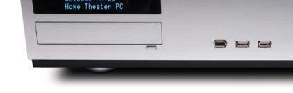
2 At Antec, we continually refine and improve our products to ensure the highest quality. So it s possible that your new case may differ slightly from the descriptions in this manual. This isn t a problem; it s simply an improvement. As of the date of publication, all features, descriptions, and illustrations in this manual are correct. Disclaimer This manual is intended only as a guide for Antec s Computer Enclosures. For more comprehensive instructions on installing your motherboard and peripherals, please refer to the user s manuals which come with your components and drives. Life Style Case Fusion User s Manual The Power Supply Fusion comes with a 430Watt universal input, active PFC single 80mm fan cooled power supply with the newest ATX12V version 2.01 specifications. This include dual 12V output rails that delivers safer and more reliable output to your system s components, as well as higher energy efficiency, which reduces power consumption by up to 25% saving you money on your electricity bill. In addition we ve included a variety of industrial-grade protective circuitry: OPP (over power protection), OVP (over voltage protection), UVP (under voltage protection), and SCP (short circuit protection). The power supply comes with a main power switch. Make sure you turn the switch to the ON ( I ) position before you boot up your computer for the first time. Normally, you won't need to switch to the OFF (O) position, since the power supply includes a soft on/off feature. This lets you turn your computer on and off by using the soft switch on your computer case. If your computer crashes and you can't shut it down using the soft switch, you can switch the main power to the OFF (O) position to clear the fault, then reboot. The power supply features Power Factor Correction (PFC) circuitry in accordance with European standard regulation code EN By altering the input current wave shape, PFC improves the power factor of the power supply. This results in increased energy efficiency, reduced heat loss, prolonged life for power distribution and consumption equipment, and improved output voltage stability. Together with the high efficiency design and the quiet 80mm fan, the power supply delivers not only cleaner but also quiet operating environment. Setting Up 1. Place the case upright on a flat, stable surface. 2. Remove the thumbscrews from the back of the top panel. Slide the panel towards the rear to remove it from the case. 3. Inside the case you should see the power supply, some wiring with marked connectors (USB, PWR etc.), and installed I/O panel and a power cord. 1
3 The Triple Chamber structure Upon opening the top panel, you will find the case is divided into three chambers the power supply chamber, the motherboard chamber and the HDD chamber. This triple chamber structure isolates the heat and noise from each other resulting in much quieter and cooler operation than a traditional desktop case. Installing the Motherboard This manual does not cover CPU, RAM, or expansion card installation. Please consult your motherboard manual for specific mounting instructions and troubleshooting. The motherboard is located inside the main chamber with two 120mm TriCool fans preinstalled at the side of the case right next to the CPU to cool the hottest CPU on the market. 1. Lay the case down, with the open side facing up. The drive cages and power supply should be visible. 2. Make sure you have the correct I/O panel for your motherboard. If the panel provided with the case isn t suitable, please contact your motherboard manufacturer for the correct I/O panel. 3. Line up your motherboard with the standoff holes, and remember which holes are lined up. Not all motherboards will match with all the provided holes; this is normal, and won t affect functionally. (In other words, there will likely be extra holes.) 4. Remove your motherboard by lifting it up. 5. Screw the brass standoffs into the threaded holes that line up with your motherboard. Do not overtighten the standoffs. Some standoffs may be pre-installed for your convenience. 6. Place your motherboard on the brass standoffs. 7. Screw in your motherboard to the standoffs with the provided Philips-head screws. Your motherboard is now installed. Connecting the Power and LED The power supply conforms to the ATX12V Version 2.01 standard. It is also backwards compatible with most previous ATX12V form factor motherboards. Before you connect the power supply to any of your devices, please consult the appropriate user manuals for your motherboard and other peripherals. Note: this power supply does not provide a 5V line. Few modern motherboards (and none compliant with ATX12V v2.0 and above) require 5V power, but if yours does then this power supply may not be compatible with it. 1. Connect the 24-pin Main Power Connector and the 4-pin connector to your motherboard as needed. If your motherboard uses a 20-pin connector; detach the 4-pin attachment on the 24-pin power connector (see pictures 1 and 2). 2. Connect the Reset switch (labeled RESET SW) to your motherboard at the RST connector. Make sure the label always faces the front of the case. 3. Power LED (labeled POWER LED) connector is located behind the Reset connector. 4. Power Switch (labeled POWER SW) connects to the PWR connector on the motherboard. 5. Hard Drive LED (labeled H.D.D. LED) connects to the IDE connector. 2 Picture 1 Picture 2 For 24-pin motherboards For 20-pin motherboards
4 Connecting the USB Ports You will find a single 10-pin connector on a cable attached to the front USB ports. This is an Intel standard connector, which is keyed so that it can t be accidentally reversed as long as it is connected to a proper Intel standard motherboard header. Connect the 10-pin connector to your motherboard headers so that the blocked pin fits over the missing header pin. Note: Please check your motherboard manual for your USB header pin layout and make sure it matches the attached table. If it does not match this Intel standard, please call Antec customer support at (800) 22ANTEC (North America) or at +31 (0) (Europe) to buy a USB adapter. This adapter will allow you to connect the front USB to your motherboard on a pin-by-pin basis. Motherboard Pin Layout Pin Signal Names Pin Signal Names 1 USB Power 1 2 USB Power 2 3 Negative Signal 1 4 Negative Signal 2 5 Positive Signal 1 6 Positive Signal 2 7 Ground 1 8 Ground 2 9 Key (No Connection) 10 Empty Pin Connecting the IEEE 1394 (FireWire, i.link ) Port You will find a single 10-pin connector on a cable attached to the front IEEE 1394 connection. This is an Intel standard connector, which is keyed so that it can t be accidentally reversed as long as it is connected to a proper Intel standard motherboard header. Connect the 10-pin connector to your motherboard header so that the blocked pin fits over the missing header pin. Note: Please check your motherboard manual for your IEEE 1394 header pin layout and make sure it matches the attached table. If you intend to connect the front FireWire port to an IEEE 1394 add-on card that comes with an external-type IEEE1394 connector, please call Antec customer service at (800) 22ANTEC (North America) or +31 (0) (Europe) to buy an adapter. This adapter will allow you to connect the front IEEE 1394 port to the external-type connector. Pin Assignment for Front Panel IEEE 1394 Connector Pin Signal Names Pin Signal Names 1 TPA+ 2 TPA 3 Ground 4 Ground 5 TPB+ 6 TPB 7 +12V (Fused) 8 +12V (Fused) 9 Key (No Pin) 10 Ground 3
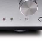
5 Connecting the Audio Ports There is an Intel standard 10-pin connector (with 7 individual wires with connectors) coming out from the front panel speaker and microphone connection. If your motherboard supports Intel s standard onboard audio connector, you can plug in the 10-pin connector directly onto the board. For non-intel standard audio connection, you need to plug the 7 individual connectors to the motherboard. See instructions below: Locate the internal audio connectors from your motherboard or sound card. Consult your motherboard or sound card manual for the pin-out positions. 1. Microphone Signal Pin: Connect the MIC connector to this pin. 2. Microphone Power: Connect the MIC-BIAS connector to this pin. 3. Ground Pin: Connect the AUD GND connector to this pin. 4. Front Right Speaker Out Pin: Connect the FPOUT-R connector to this pin. 5. Front Left Speaker Out Pin: Connect the FPOUT-L connector to this pin. 6. Rear Right Speaker Out Pin: Connect the RET-R connector to this pin. 7. Rear Left Speaker Out Pin: Connect RET-L connector to this pin. The VFD Display/Volume Control Fusion comes with a Vacuum Fluorescent Display (VFD) and a volume control to work with your media center application. 1. Make sure the power supply is off and unplugged before installing any hardware. 2. Connect the 4 pin power cable from the VFD to the power supply 4 pin (Floppy) connector 3. Your VFD comes with a 4 pin internal USB adapter (see picture 3) and standard external USB connector (Default). a) To use the external connector to connect to a standard USB port or: b) Check your motherboard USB header pin layout. Match the internal adapter to your motherboard header. Plug the internal adapter into the external connector and plug it in to your motherboard s USB header. 4. Plug in your power supply, and turn it on. 5. Boot up your computer. 6. Insert the provided driver CD into your optical drive. 7. Restart again after the driver has been installed. Note: This VFD is intended to be compatible with Microsoft MCE. The basic features include: System Information, Media Information, check, Daily news, City information (weather report), and graphic equalizer. Hard disk Drive Installation There is a hard disk drive bracket with soft silicone grommets inside the HDD chamber. It can hold two hard drives. 1. Remove the HDD bracket from the chamber by removing the two screws on top of it. 4 Picture 3


6 2. Mount the left side of your hard drives (facing from the front of the hard drive) onto the drive bracket through the top silicone grommets with the special screws provided (see picture 4). Don t over-tighten. Over-tightening the screws will harm the vibration and noise reducing ability of the silicone grommets. 3. Drop the HDD/bracket assembly back into the case. Each hard drive should rest on two soft silicone grommets preinstalled at the bottom of the case. 4. Fasten the bracket using the screws provided. 5. Find a 4-pin Molex or a SATA connector on the Picture 4 power supply and connect it to the male 4-pin connector on the device Device Installation This case comes with one 5.25 external drive bay right under the VFD. To install the external 5.25 device: 1. Remove the flip-up drive cage. 2. Insert the 5 25 device into the lower 5.25 drive bay of the cage. Make sure to use the rear set of screw holes on the cage to mount the device. Fasten the drive with the screws included. (See Picture 5) Note: the upper 5.25 drive bay is reserved for VFD. Do not mount any device into this bay. Picture 5 3. Find a 4-pin Molex connector on the power supply and connect it to the male 4-pin connector on the device. Cooling System The 120mm TriCool fans The Fusion comes with two 120mm TriCool fans preinstalled at the side of the case inside the motherboard chamber. These two fans sit right next to the CPU to cool the hottest CPU on the market. Note: The default setting of the fan is Low. We recommend this speed for maximum quiet computing. This fan has a three-speed switch that lets you choose between quiet, performance, or maximum cooling. (See specifications below.) The fan is installed so that the air is blowing out of the case. Connect a large 4-pin connector from the power supply to the male 4-pin connector on the fan. Note: The minimum voltage to start the fan is 5V. We recommend that our users set the fan speed to High if you choose to connect the fan to a fan control device or to the Fan-Only connector found on some Antec power supplies. A fan-controldevice regulates the fan speed by varying the voltage to it. The voltage may start as low as 4.5V to 5V. Connecting a TriCool set on Medium or Low to a fan-control device may result in the fan not being able to start. The already lowered voltage from the fan control device will be further reduced by the TriCool circuitry below 5V. 5
7 Specifications: Size: 120 x 120 x 25.4mm Rated Voltage: DC 12V Operating Voltage: 10.2V ~ 13.8V Speed Input Current Air Flow Static Pressure Acoustical Noise Input Power High 2000 RPM 0.24A (Max.) 2.24 m³ / min (79 CFM) 2.54 mm-h2o (0.10 inch-h2o) 30 dba 2.9 W Medium 1600 RPM Low 1200 RPM 0.2A 1.59 m³ / min (56 CFM) 1.53 mm-h2o (0.06 inch-h2o) 28 dba 2.4 W 0.13A 1.1 m³ / min (39 CFM) 0.92 mm-h2o (0.04 inch-h2o) 25 dba 1.6 W The Bottom Air Intake There are intake vents at the bottom of the case right under the HDD chamber. Fresh cool air will flow through the vents through the hard drives, and then flow into the motherboard chamber and exhaust by the two 120mm TriCool fans. Note: do not place the Fusion on a soft surface or over anything that will block the bottom air vents The Upper Air Intake There are vents on the top panel above the PCI expansion slot. Fresh cool air will flow through it into the motherboard chamber to cool the hottest VGA card. Note: do not place anything on top of the Fusion that will block the top air vents The Rear Air Intake There are vents right above the rear I/O panel and on the PCI expansion slot covers to bring in fresh cool air to help cool the CPU and VGA card. CPU Air Guide Integrated with the CPU Air Guide, fresh air from the rear air intake can be directed to the CPU cooler to enhance the CPU cooling. CPU Guide consists of several sections which can be adjusted by adding or removing it to best suit each individual motherboard CPU position. The Power Supply Air Intake There are vents on the left side of the case to bring fresh cool air into the power supply chamber to cool the power supply. Note: please leave at least 1 (2.5cm) between the left side of the case and anything that could block airflow to the power supply. This is required so that the power supply will have sufficient cooling. 6
8 Antec, Inc Fremont Blvd. Fremont, CA USA tel: fax: Antec Europe B.V. Sydneystraat BP Rotterdam The Netherlands tel: +31 (0) fax: +31 (0) Customer Support: US & Canada ANTEC Europe +31 (0) Copyright 2006 Antec, Inc. All rights reserved. All trademarks are the property of their respective owners. Reproduction in whole or in part without written permission is prohibited. Printed in China. Version /02/2006
Media Components. Fusion v2/fusion Black User s Manual. Manuel de l utilisateur Anwenderhandbuch Manuale per l operatore Manual del usuario
 TM Media Components Fusion v2/fusion Black User s Manual Manuel de l utilisateur Anwenderhandbuch Manuale per l operatore Manual del usuario At Antec, we continually refine and improve our products to
Atlas Quiet Mini Server Case. User s Manual Manuel de l utilisateur Anwenderhandbuch Manuale per l operatore Manual del usuario
 Atlas Quiet Mini Server Case User s Manual Manuel de l utilisateur Anwenderhandbuch Manuale per l operatore Manual del usuario 1 At Antec, we continually refine and improve our products to ensure the highest
Atlas 550 Quiet Mini Server Case. User s Manual Manuel de l utilisateur Anwenderhandbuch Manuale per l operatore Manual del usuario
 Atlas 550 Quiet Mini Server Case User s Manual Manuel de l utilisateur Anwenderhandbuch Manuale per l operatore Manual del usuario At Antec, we continually refine and improve our products to ensure the
Media Components. Micro Fusion Remote 350 User s Manual. Manuel de l utilisateur Anwenderhandbuch Manuale per l operatore Manual del usuario
 TM Media Components Micro Fusion Remote 350 User s Manual Manuel de l utilisateur Anwenderhandbuch Manuale per l operatore Manual del usuario At Antec, we continually refine and improve our products to
Three Hundred. User s Manual Manuel de l utilisateur Anwenderhandbuch Manuale per l operatore Manual del usuario
 Three Hundred User s Manual Manuel de l utilisateur Anwenderhandbuch Manuale per l operatore Manual del usuario At Antec, we continually refine and improve our products to ensure the highest quality. As
NSK 4482 / NSK 4482B User s Manual
 NSK 4482 / NSK 4482B User s Manual Table of Contents Introduction 1.1 Case Specifications......... 2 1.2 Diagram......... 2 Hardware Installation Guide 2.1 Setting Up.......... 3 2.2 Motherboard Installation.......
Sonata Solo / Solo White / Designer 500 / Plus 550 User s Manual
 Sonata Solo / Solo White / Designer 500 / Plus 550 User s Manual Manuel de l utilisateur Anwenderhandbuch Manuale per l operatore Manual del usuario At Antec, we continually refine and improve our products
WALLET-FRIENDLY INTENSITY
 O N E H U N D R E D WALLET-FRIENDLY INTENSITY U S E R M A N U A L ONE HUNDRED USER MANUAL Congratulations on your purchase of the Antec One Hundred. Antec s One Hundred is the gaming case that delivers
P160 User s Manual Manuel de l utilisateur Anwenderhandbuch Manuale per l operatore Manual del usuario
 P10 User s Manual Manuel de l utilisateur Anwenderhandbuch Manuale per l operatore Manual del usuario At Antec, we continually refine and improve our products to ensure the highest quality. So it's possible
User s Manual Manuel de l utilisateur Anwenderhandbuch Manuale per l operatore Manual del usuario
 Antec, Inc. 47900 Fremont Blvd. Fremont, CA 94538 tel: 510-770-1200 fax: 510-770-1288 Antec Europe B.V. Sydneystraat 33 3047 BP Rotterdam The Netherlands tel: +31 (10)462-2060 fax: +31 (10)437-1752 Technical
EARTHWATTS 750 GREEN POWER SUPPLY USER S MANUAL
 EARTHWATTS 750 GREEN POWER SUPPLY USER S MANUAL USER S MANUAL EARTHWATTS SERIES EA-750 GREEN POWER SUPPLY THE ENERGY-EFFICIENT PSU Get more power and lower your electric bill with the new EarthWatts Green
Antec Signature Series
 USER S MANUAL Antec Signature Series SG-650 and SG-850 Power Supply A New Level of Quality The Signature Series is Antec s premium line of high-end performance power supplies. Combining cutting-edge technology,
TRUEPOWER NEW 550-WATT POWER SUPPLY USER S MANUAL
 TRUEPOWER NEW 550-WATT POWER SUPPLY USER S MANUAL USER S MANUAL TRUEPOWER NEW SERIES TP-550 POWER SUPPLY THE ADVANCED PSU SOLUTION The TruePower New series is Antec s full featured line of high-quality,
TRUEPOWER QUATTRO 1200-WATT POWER SUPPLY USER S MANUAL
 TRUEPOWER QUATTRO 1200-WATT POWER SUPPLY USER S MANUAL USER S MANUAL TRUEPOWER QUATTRO SERIES TPQ-1200 POWER SUPPLY HIGH-PERFORMANCE POWER SUPPLY The TPQ-1200 goes beyond the kilowatt range of standard
RIOTORO CR1080. Installation Guide
 RIOTORO CR1080 Installation Guide Welcome to RIOTORO Thank you for purchasing the RIOTORO CR1080 Computer Case The CR1080 chassis squeezes raw computing power into in a cool, quiet and elegant PC that
EA-750 Platinum POWER SUPPLY USER S MANUAL
 EA-750 Platinum POWER SUPPLY USER S MANUAL 1 EA-750 Platinum POWER SUPPLY Antec s EarthWatts Platinum is one of the most efficient PSU series ever created. With an 80 PLUS PLATINUM rating, the highest
Lexa S. User s manual
 Lexa S User s manual Thank you. Dear valued customers, Thank you for purchasing our product. We are thankful to all our fans for the continuing support, after just four years since entering the computer
CONTENTS. 1. Motherboard installation Install 5¼ and 3½ drives Install PCI components Case fan setup...5
 USER S MANUAL CONTENTS 1. Motherboard installation...1 2. Install 5¼ and 3½ drives...3 3. Install PCI components...4 4. Case fan setup...5 5. Connect case leads to motherboard...6 6. Identify the power
CONTENTS. 1. Motherboard installation Install 3½ and 5¼ drives Install PCI components Connect case leads to motherboard...
 CONTENTS 1. Motherboard installation... 1 2. Install 3½ and 5¼ drives... 3 3. Install PCI components... 4 4. Connect case leads to motherboard... 5 5. Case fan setup... 5 6. Optional device installation...
TP-650C POWER SUPPLY USER S MANUAL
 TP-650C POWER SUPPLY USER S MANUAL V1.1 1 TP-650C Antec s TruePower Classic series sets new standards for power supplies. TruePower Classic is one of the first series to comply with the toughest energy
VF6000 Series. Tested To Comply With FCC Standards FOR HOME OR OFFICE USE
 VF6000 Series C 006 Thermaltake Technology Co., Ltd. All Rights Reserved. 006. All other registered trademarks belong to their respective companies. www.thermaltake.com Tested To Comply With FCC Standards
CK-1026 series User's Manual
 Contents Chapter l Product Introduction. Specification Chapter 2 Case Mechanical Operation 2. How to remove/install the side panel 2 2.2 5.25" & 3.5" Device Installation 3 2.3 PCI slot tool-free function
C 2006 Thermaltake Technology Co.,Ltd. All Rights Reserved. VD6000 SERIES. User Manual
 C 2006 Thermaltake Technology Co.,Ltd. All Rights Reserved. VD6000 SERIES User Manual Contents Chapter l Product Introduction 1.1 Specification 2 Chapter 2 Case Mechanical Operation 2.1 How to open the
TP-550G POWER SUPPLY USER S MANUAL
 TP-550G POWER SUPPLY USER S MANUAL 1 TP-550G Antec s TruePower Gold series sets new standards for power supplies. TruePower Gold is one of the first series to comply with the toughest energy standard available,
Dream. User's Manual. C 2004 Thermaltake Technology Co.,Ltd. All Rights Reserved.
 Dream User's Manual www.thermaltake.com C 004 Thermaltake Technology Co.,Ltd. All Rights Reserved. Contents Chapter l Product Introduction. Specification Chapter Case Mechanical Operation. How to open
HOME THEATER PC CHASSIS
 HOME THEATER PC CHASSIS Model: HTPC 280 BAV4 & SAV4 Color: Black & Silver Quick Installation Guide (U.S. & Canada Only) Version 1.0 DISCLAIMER No warranty or representation, either expressed or implied,
LC18. Specification: Product Overview. Touch Screen
 LC18 Product Overview LC18 Specification: Material: Aluminum front panel, 1.5mm aluminum body Color: Black & Silver Motherboard: ATX, Micro ATX Drive Bay: External - 5.25" x 2 External - 3.5" x 1 Internal
EA550G PRO POWER SUPPLY USER S MANUAL
 EA550G PRO POWER SUPPLY USER S MANUAL 1 EA550G PRO Featuring hybrid modular cable management, EarthWatts GOLD PRO gives you a cooler, quieter system all powered by Continuous Power. By using a PSU that
Home Theater PC Chassis
 Home Theater PC Chassis Model: HTPC 300 BA & SA Color: Black & Silver Quick Installation Guide (U.S. & Canada Only) Version 1.0 DISCLAIMER No warranty or representation, either expressed or implied, is
CARBIDE SERIES HIGH AIRFLOW MID-TOWER CASE INSTALLATION GUIDE
 CARBIDE SERIES HIGH AIRFLOW MID-TOWER CASE INSTALLATION GUIDE ! CONGRATULATIONS! CONTENTS Congratulations on your new Carbide Series Air 540. With its Direct Airflow Path design and tons of easy-to-use
TABLE OF CONTENTS. 1. General 3
 Manual TABLE OF CONTENTS 1. General 3 2. Specifications 3 2.1 Overview SHP550 V2 3 2.2 Overview SHP650 V2 3 2.3 Mains Voltage and Protections 4 2.4 Safety Certifications 4 3. Package Contents 4 4. Cable
Duet. U se r s m a n u a l
 Duet U se r s m a n u a l Thank you. Dear Valued Customers, Thank you for purchasing our product. With the booming of the gaming market and computer cases, NZXT would like to differentiate ourselves from
Computer Assembly (Installing Mother Board & CPU)
") Computer Assembly (Installing Mother Board & CPU) IT@SCHOOL HARDWARE TEAM Biju Thiruvananthapuram Sree Kumar Kottarakkara Shamsudeen Attingal Pradeep Mattara Wandoor Pre-Installation Precaution Mother
Computer Assembly (Installing Mother Board & CPU) IT@SCHOOL HARDWARE TEAM Biju Thiruvananthapuram Sree Kumar Kottarakkara Shamsudeen Attingal Pradeep Mattara Wandoor Pre-Installation Precaution Mother
BETA Evo. User s manual
 BETA Evo User s manual Thank you. Dear valued customers, Thank you for purchasing our product. We are thankful to all our fans for the continuing support, after just four years since entering the computer
TABLE OF CONTENTS. 1. General Specifications Overview Mains Voltage and Protections Safety Certifications 5
 Manual TABLE OF CONTENTS 1. General 3 2. Specifications 3 2.1 Overview 3 2.2 Mains Voltage and Protections 4 2.3 Safety Certifications 5 3. Package Contents 5 4. Cable Configuration 5 4.1 Connection Options
TABLE OF CONTENTS. 1. General Specifications Overview Mains Voltage and Protections Safety Certifications 4
 Manual TABLE OF CONTENTS 1. General 3 2. Specifications 3 2.1 Overview 3 2.2 Mains Voltage and Protections 4 2.3 Safety Certifications 4 3. Package Contents 5 4. Modular System of the Power Supply 5 4.1
Chapter 3: Computer Assembly
 Chapter 3: Computer Assembly IT Essentials v6.0 ITE v6.0 1 Chapter 3 - Sections & Objectives 3.1 Assemble the Computer Build a Computer. 3.2 Boot the Computer Explain how to verify BIOS and UEFI settings.
HCG-520M POWER SUPPLY USER S MANUAL
 HCG-520M POWER SUPPLY USER S MANUAL 1 HCG-520M The HCG-520M uses Intelligent Hybrid Cable Management. Cables that are important or mandatory are permanently connected to the PSU for the highest quality
(Hardware and case keys are provided inside the chassis storage compartment.)
") 1. Motherboard installation...1 2. Install 3½ and 5¼ drives...3 3. Install PCI components...4 4. Fan installation and setup...5 5. Temperature probe setup...6 6. Connect case leads to motherboard...7 7.
1. Motherboard installation...1 2. Install 3½ and 5¼ drives...3 3. Install PCI components...4 4. Fan installation and setup...5 5. Temperature probe setup...6 6. Connect case leads to motherboard...7 7.
All other registered trademarks belong to their respective companies. C 2007 Thermaltake Technology Co.,Ltd. All Rights Reserved.
 All other registered trademarks belong to their respective companies. C 2007 Thermaltake Technology Co.,Ltd. All Rights Reserved. www.thermaltake.com User's Manual Contents Chapter 1. Product Introduction
All other registered trademarks belong to their respective companies. C 2007 Thermaltake Technology Co.,Ltd. All Rights Reserved.
 All other registered trademarks belong to their respective companies. C 2007 Thermaltake Technology Co.,Ltd. All Rights Reserved. www.thermaltake.com User's Manual VG7000 Series Contens Chapter 1. Product
HOME THEATER PC CHASSIS
 HOME THEATER PC CHASSIS Model: HTPC 400 BA & SA Color: Black & Silver Quick Installation Guide (U.S. & Canada Only) Version 1.0 DISCLAIMER No warranty or representation, either expressed or implied, is
HIGH AIRFLOW MID-TOWER CASE INSTALLATION GUIDE
 CARBIDE SERIES 740 HIGH AIRFLOW MID-TOWER CASE INSTALLATION GUIDE ! CONGRATULATIONS! CONTENTS Congratulations on your new Carbide Series Air 740. With its Direct Airflow Path design and tons of easy-touse
R-4 Bulldozer user s Manual
 R-4 Bulldozer user s Manual G.M.Corporation co.,ltd. 12 th, Daeyoung B/D, 44-1, Yoido-Dong, Youngdeungpo-gu, Seoul, Korea Tel : 82-2-761-9594 Fax : 82-2-761-9585 E-mail : gmcsales@gmc.co.kr www.gmc.co.kr
760T GRAPHITE SERIES GRAPHITE SERIES 760T FULL-TOWER PC CASE INSTALLATION GUIDE
 GRAPHITE SERIES 760T GRAPHITE SERIES 760T FULL-TOWER PC CASE INSTALLATION GUIDE ! CONGRATULATIONS! CONTENTS Thank you for purchasing a Graphite Series 760T Full-Tower PC case. Graphite Series 760T full-tower
NINETEEN HUNDRED. User Manual
 NINETEEN HUNDRED User Manual Congratulations on your purchase of the Antec Nineteen Hundred!! Nineteen Hundred User Manual Meet the Nineteen Hundred, a case engineered for performance and built to enclose
HD160XT Plus. English version
 English version www.zalman.co.kr www.zalmanusa.com Introduction Congratulations on your purchase of Zalman s HD160XT Plus Home Theatre PC Enclosure! You are now about to experience Zalman s world of silent
DEFINE XL COMPUTER DEFINE XL COMPUTER CASE CASE
 DEFINE XL COMPUTER DEFINE XL COMPUTER CASE CASE USER S MANUAL 1.1 Thank you and congratulations on your purchase of your new Fractal Design Define XL ATX Computer Case! Before using the case, please take
After completing this chapter, you will meet these objectives:
 3.0 Introduction Assembling computers is a large part of a technician's job. As a technician, you will need to work in a logical, methodical manner when working with computer components. As with any learned
Page
 Page 2... 3... 4... 5-6... 7... 8... 9-11... 12... 13... 14-15... Index, Foreword Product Overview Preparation for Assembly Installing the Motherboard Installing Case Fan & Optional IRRC Wiring Diagram
EDG750 POWER SUPPLY USER S MANUAL
 EDG750 POWER SUPPLY USER S MANUAL 1 EDG750 Antec s EDGE series is the pinnacle of power supplies. EDGE is fully modular with a revolutionary 18+10-pin MBU socket for the needs of tomorrow. By using a PSU
HCP-850 Platinum POWER SUPPLY USER S MANUAL
 HCP-850 Platinum POWER SUPPLY USER S MANUAL 1 HCP-850 Platinum Antec s High Current Pro Platinum series is the pinnacle of power supplies. High Current Pro Platinum is fully modular with a revolutionary
Poseidon. User s Manual GZ-XA1CA-STB GZ-XA1CA-STS GZXA1CA-STBSTS rev. 1002
 Poseidon GZ-XA1CA-STB GZ-XA1CA-STS User s Manual 20070301-GZXA1CA-STBSTS rev. 1002 Poseidon Introduction The chassis of Gigabyte Poseidon series is made by high-end Aluminum bezel design with dual 12cm
Thank you. Dear Valued Customers,
 Hush User s manual Thank you. Dear Valued Customers, Thank you for purchasing our product. With the booming of the gaming market and computer cases, NZXT would like to differentiate ourselves from other
CARBIDE SERIES SMALL FORM FACTOR PC CASE
 CARBIDE SERIES SMALL FORM FACTOR PC CASE INSTALLATION GUIDE Table of Contents Case Specifications Congratulations:... 1 Removing the side panels:... 5 Installing the motherboard:... 5 Installing the PSU:...
HOME THEATER PC CHASSIS. Model: HTPC 7000B. HTPC Chassis Quick Installation Guide
 HOME THEATER PC CHASSIS Model: HTPC 7000B HTPC Chassis Quick Installation Guide (U.S. & Canada Only) Version 1.0 DISCLAIMER No warranty or representation, either expressed or implied, is made with respect
OBSIDIAN SERIES 250D OBSIDIAN SERIES. OBSIDIAN SERIES 250D Mini ITX PC CASE INSTALLATION GUIDE
 OBSIDIAN SERIES 50D OBSIDIAN SERIES 50D Mini ITX PC CASE OBSIDIAN SERIES INSTALLATION GUIDE ! CONGRATULATIONS! Thank you for purchasing an Obsidian Series 50D Mini ITX PC case. Obsidian Series 50D Mini
Reliable ATX 12V 2.01 Power Supply
 Reliable ATX 12V 2.01 Power Supply 350 Watt Reliable Power Supply 400 Watt Reliable Power Supply 450 Watt Reliable Power Supply ATX2POWER350 ATX2POWER400 ATX2POWER450 Actual product may vary from photo
Dagger Series. Introduction. Features 500W / 600W. DC to DC Module Design Providing high efficient, stable power
 Introduction Dagger Series, FSP brand new 80 PLUS gold SFX PSU, featured with fully- modular, flat ribbon cables and DC to DC module design in a compact size which is suitable for small pc host machines,
OBSIDIAN SERIES 750D. Obsidian Series 750D Full-Tower PC Case INSTALLATION GUIDE
 OBSIDIAN SERIES 750D Obsidian Series 750D Full-Tower PC Case INSTALLATION GUIDE ! CONGRATULATIONS! CONTENTS Thank you for purchasing an Obsidian Series 750D Full-Tower PC case. Obsidian Series 750D Full-Tower
450D OBSIDIAN SERIES OBSIDIAN SERIES 450D MID-TOWER PC CASE INSTALLATION GUIDE
 OBSIDIAN SERIES 450D OBSIDIAN SERIES 450D MID-TOWER PC CASE INSTALLATION GUIDE ! CONGRATULATIONS! Thank you for purchasing an Obsidian Series 450D Mid-Tower PC case. Obsidian Series 450D Mid Tower Case
DNS User Manual. Version Dec DataON Storage, storage division of Area Data Systems.
 DNS-2670 User Manual Version Dec. 2015 DataON Storage, storage division of Area Data Systems. Contents 1 Introduction... 1 1.1 System Overview... 3 1.1.1 System Top View...3 1.1.2 Front View...4 1.1.3
Computer Maintenance. PC Disassembly and Reassembly. Copyright Texas Education Agency, All rights reserved.
 Computer Maintenance PC Disassembly and Reassembly 1 Enabling Objectives Computer Chassis (Cases) Power Supplies Configuring the Motherboard Configuring the Connectors CPU Interfaces RAM Installing a Hard
CR1288 prism. Installation Guide
 CR1288 prism Installation Guide Congratulations! You are on your way to building your dream machine! Contents Chapter 1: Before You Begin - What's in the box - Product details - Before you begin Chapter
EVGA assumes you have purchased all necessary parts needed to allow for proper system functionality.
 Before You Begin Parts NOT in the Kit This kit contains all the hardware necessary to install and connect your new EVGA e-7050/610i GPU motherboard with integrated GeForce graphics processing. However,
Power Supplies. Chapter The McGraw-Hill Companies, Inc. All rights reserved. Mike Meyers CompTIA A+ Guide to Managing and Troubleshooting PCs
 Power Supplies Chapter 10 Overview In this chapter, you will learn how to Explain the basics of electricity Describe the details about powering the PC Install and maintain power supplies Understand power-supply
ATX12V 2.2 Power Supply for HP & Compaq Systems
 ATX12V 2.2 Power Supply for HP & Compaq Systems 350 Watt ATX12V 2.2 Power Supply 400 Watt ATX12V 2.2 Power Supply ATXPW350HPCQ ATXPW400HPCQ Actual product may vary from photo FCC Compliance Statement This
I. Introduction 02 Specifications 02 Accessories 02 Features 03
 I. Introduction 02 Specifications 02 Accessories 02 Features 03 II. Installation Instructions 03 1. Installation of the motherboard 03 2. Installation of optical drives and removal of the 5.25 inch cage
CHASSIS INSTALLATION GUIDE
 SUPER SC942S-600 SC942i-600/550 SC942 CHASSIS INSTALLATION GUIDE 1.0 SUPER SC942 Chassis User's Guide Table of Contents Chapter I: Unpacking and Check Lists... 1-3 Chapter 2: Installation Procedures...
E4233. English. P-Series. ASUS PC (Desktop Barebone) Installation manual. Download the latest manual from the ASUS website:
 Installation manual. Download the latest manual from the ASUS website:") E P-Series ASUS PC (Desktop Barebone) Installation manual P P Download the latest manual from the ASUS website: www.asus.com Front/Rear panel features P Front (Close) P Front (Close) Front (Open) Rear
E P-Series ASUS PC (Desktop Barebone) Installation manual P P Download the latest manual from the ASUS website: www.asus.com Front/Rear panel features P Front (Close) P Front (Close) Front (Open) Rear
I. Introduction 02 Introduction Accessories
 I. Introduction 02 Introduction Accessories 02 02 Features 03 II. Installation Instructions 03 1. Installation of the motherboard 03 2. Installation of optical drives and removal of the 5.25 inch cage
PH-M3x5. Contents. Page COPYRIGHT NOTICE
 Page 2... 3... 4... 5-6... 6-7... 8... 9.............. 10-12... 13... 14... 15... Contents Index, Message, Introduction Product Overview Preparation for Assembly Installing the Motherboard Installing the
Page. Foreword. We sincerely hope that you enjoy using our product! P2 - INDEX
 Page 2... Index, Foreword 3... Product Overview 4... Preparation for Assembly 5-6... Installing the Motherboard 7... PCB Wiring Diagram 8... Fitting the Optical & Hard Drives 9... Installing the PCI Card
Motherboard Central Processing Unit (CPU) Random access memory (RAM)
 Random access memory (RAM)") Cool Careers in Cyber Security Missing Computer Parts Delivery: Can be used as a table demo (hands-on) activity or during a presentation session. Large display table recommended. Pre-cut and laminate the
Cool Careers in Cyber Security Missing Computer Parts Delivery: Can be used as a table demo (hands-on) activity or during a presentation session. Large display table recommended. Pre-cut and laminate the
English version. HD160 Plus
 English version Please read this manual thoroughly before installation. Please visit our website and watch the HD160 Plus installation video to assist you in the installation process. E-mail: zalman@zalman.co.kr
NZXT. CRAFTED GAMING ARMOR. TRINITY. User s manual NZXT. 1
 NZXT. CRAFTED GAMING ARMOR. TRINITY User s manual NZXT. 1 Thank you. Dear Valued Customers, Thank you for purchasing our product. With the booming of the gaming market and computer cases, NZXT would like
H4 Series Hardware Replacement Guide
 Machine type: 10059/7723 10060/7724 10068/7752 10080/3099/1194 10091/2558/1196 H4 Series Hardware Replacement Guide Version 3.0 2011.08 31500379 Hardware Replacement Guide Copyright Lenovo 2011. All rights
Computer Assembly Step by Step DRAFT
 9781587132636_ch03.qxp 8/20/10 1:37 PM Page 79 CHAPTER 3 Computer Assembly Step by Step Objectives Upon completion of this chapter, you should be able to answer the following questions: How do I open the
Thermaltake View 37 Mid Tower. Style:Simple. Main Feature
 Style:Simple Size: Mid-tower support up to E-ATX MB Material: Steel & Plastic Main Feature Connection : Top-Front I/O ports with 2 x USB 3.0 and 2 x USB 2.0 Ventilation : 2 preinstalled 140mm fans with
How to Assemble a Desktop PC
 How to Assemble a Desktop PC By Taylor Koch iii Table of Contents Introduction to Building a Desktop PC... 1 Preparation and Precautions... 3 PC Parts... 3 Basic Tools... 3 Safety Precautions... 3 Installing
AC4G-D User s Manual
 AC4G-D User s Manual Entire contents of this manual 2004 Active Cool Ltd. Ashkelon, Israel. Reproduction in whole or in part without permission is prohibited. Active Cool and AC4G-D are registered of Active
DC-DC TECHNOLOGY DC-DC technology provides highest efficiency, most stable performance, and perfect regulation (Regulation <3%).
.") COMPATIBLE WITH LATEST PC-TECHNOLOGY Supports the newest specifications of ATX12V Created for usage with current and next-generation multi-core CPU platforms. SUPPORT MULTI-GPU TECHNOLOGY Support PCI Express
COMPATIBLE WITH LATEST PC-TECHNOLOGY Supports the newest specifications of ATX12V Created for usage with current and next-generation multi-core CPU platforms. SUPPORT MULTI-GPU TECHNOLOGY Support PCI Express
1. Safety Precautions. 2. Components. 3. Notes on Installation. Caution. Warning
 1. Safety Precautions The following precautions and directions are measures against possible accidents and injuries. Please read them thoroughly before using this product. Warning Neglecting the following
Introduction 02. Specifications 02 Accessories 02 Features 03. II. Installation Instructions. 1. Installation of the motherboard
 Introduction 02 Specifications 02 Accessories 02 Features 03 II. Installation Instructions 03 1. Installation of the motherboard 03 2. Installation options of hard disks 03 2.1 Mounting of the 3.5 inch
English User's Manual For SUMO Series SUMO GZ-FS1CCA-ANS/ANB/ATS/ATB SUMO GZ-FS2CCA-AJS/AJB SUMO GZ-FA1CAR-AJS/AJB
 English User's Manual For SUMO Series SUMO 4192 - GZ-FS1CCA-ANS/ANB/ATS/ATB SUMO 4198 - GZ-FS2CCA-AJS/AJB SUMO 5115 - GZ-FA1CAR-AJS/AJB Thank you for purchasing a GIGABYTE Chassis. GIGABYTE is dedicated
Introduction: Premium Power. Table of contents. Safety Information. Introduction...3. Safety Information...3. Features...4. Installation...
 1000W PLATINUM Power Supply User Manual Table of contents Introduction...3 Safety Information...3 Features...4 Introduction: Premium Power Thank you for purchasing an EVGA SuperNOVA PLATINUM series power
1500W Power Supply User Manual
 Table of contents Introduction...3 Safety Information...3 Features...4 Installation...4 Advanced Features...6 Cable Configuration...7 Specification...8 DIP Switches...9 2 Introduction: Premium Power Thank
PPower Supply Series
 Power Supply Series PPower Supply Series Watt 550/650/700 Watt 5550/650/700 Features 80 PLUS Bronze 84 to 88 percent efficiency at 230V and 20 to 100 percent load. 80 PLUS Bronze certified. ErP Lot 6 2013
SPEC-02 CARBIDE SERIES MID-TOWER GAMING CASE INSTALLATION GUIDE
 CARBIDE SERIES SPEC-02 MID-TOWER GAMING CASE INSTALLATION GUIDE Table of Contents Case Specifications Congratulations:...1 Case specifications:...2 Accessory kit contents:...3 Case features:...4 Removing
1. Safety Precautions. 2. Components. 3. Notes on Installation. Caution. Warning
 1. Safety Precautions The following precautions and directions are measures against possible accidents and injuries. Please read them thoroughly before using this product. Warning Neglecting the following
80 PLUS Test Type 115V Internal Non-Redundant 230V Internal Redundant Frac on of Rated Load 20% 50% 100% 20% 50% 100%
 CONTENTS 1 x OCZ ZX Series Power Supply 1 x AC Power Cord 1 x Modular Cables Pack 1 x Screw Pack 1 x User Manual & Certificate 80 PLUS CERTIFICATE 80 PLUS is an innovative, electric utility-funded incentive
4. Screw the Stand-offs onto the holes of the motherboard tray. 2. Slide the top cover backward slowly and lift it up to remove it.
 LC03 / LC03V 1. Unscrew the screw on the rear part of the top cover. 2. Slide the top cover backward slowly and lift it up to remove it. 3. Unscrew two screws attached on the motherboard tray to remove
This is a learning module for a specific Learning Outcome as stipulated in the HSP that is :
 1. What is it? This is a learning module for a specific Learning Outcome as stipulated in the HSP that is : Ä Ä Ä 2.4.1 Personal Computer (PC) Assembling 2.4.2 Hard disk partitioning and formatting 2.4.3
Upgrading the Mark5 motherboard to the SE7520BD2 Server Board
 Upgrading the Mark5 motherboard to the SE7520BD2 Server Board Joint Institute for VLBI in Europe Martin Leeuwinga (leeuwinga@jive.nl) February 2008 1. Introduction This document describes how to upgrade
INFORMATION AND COMMUNICATION TECHNOLOGY
 INFORMATION AND COMMUNICATION TECHNOLOGY LEARNING MODULE COMPUTER SYSTEM MODULE 2.4 Pusat Perkembangan Kurikulum Kementerian Pelajaran Malaysia 2006 1. What is it? This is a learning module for a specific
TRC-190 User s Manual
 First Edition, November 2008 www.moxa.com/product 2008 Moxa Inc. All rights reserved. Reproduction without permission is prohibited. The software described in this manual is furnished under a license agreement
CONTENTS. Thank you for purchasing a High-Quality Rosewill Product.
 User's Manual CASE Star Predator Product Overview CONTENTS Disassemble Chart P. 2 Top I/O Functions P. 2 Accessory Box P. 3 Installation Guide 1. Open Chassis P. 4 2. Install Power Supply P. 4 3. Install
USB Port Bay Hub Quick Installation Guide
 USB 2.0+1394 6-Port Bay Hub Quick Installation Guide Introducing the USB 2.0+1394 Bay Hub The USB 2.0+1394 6-Port Bay Hub is designed to support USB 2.0 and 1394 equipped PC computers. This USB 2.0+1394
User s Guide. for Echo Express SE II Thunderbolt 2-to-PCI Express Card Expansion Chassis. For Windows
 User s Guide for Echo Express SE II Thunderbolt 2-to-PCI Express Card Expansion Chassis For Windows Contents 1 Introduction, System Requirements 1 2 Echo Express SE II Description 2 Echo Express SE II