Universal Serial Bus Implementers Forum Host High-speed Electrical Test Procedure for LeCroy
|
|
|
- Helen Jacobs
- 6 years ago
- Views:
Transcription
1 Universal Serial Bus Implementers Forum Host High-speed Electrical Test Procedure for LeCroy Revision 1.0 Dec. 3,
2 Revision History Rev Date Filename Comments 0.9 (Beta) May Host HS Test for lecroy.doc Primary version of High Speed Test Procedure adapted to Agilent test equipment based on the test procedure created by USB-IF (version 0.9) 1.0 Dec Lecroy hs host rev 1.doc Approved by USB-IF Please send comments via electronic mail to techsup usb.org USB-IF High-speed Electrical Test Procedure Copyright 2001, USB Implementers Forum, Inc. All rights reserved.
3 DISCLAIMER OF WARRANTIES THIS SPECIFICATION IS PROVIDED AS IS AND WITH NO WARRANTIES OF ANY KIND, EXPRESS OR IMPLIED, INCLUDING, WITHOUT LIMITATION, NO WARRANTY OF NONINFRINGEMENT, NO WARRANTY OF MERCHANTABILITY, NO WARRANTY OF FITNESS FOR A PARTICULAR PURPOSE, NO WARRANTY OF TITLE, AND NO WARRANTY ARISING OUT OF ANY PROPOSAL, SPECIFICATION, OR SAMPLE, ALL OF WHICH WARRANTIES ARE EXPRESSLY DISCLAIMED. WITHOUT LIMITING THE GENERALITY OF THE FOREGOING, USB-IF AND THE AUTHORS OF THE SPECIFICATION DO NOT WARRANT OR REPRESENT THAT USE OF THE SPECIFICATION WILL NOT INFRINGE THE INTELLECTUAL PROPERTY RIGHTS OF OTHERS. USERS OF THE SPECIFICATIONASSUME ALL RISK OF SUCHINFRINGEMENT, AND AGREE THAT THEY WILL MAKE NO CLAIM AGAINST USB-IF OR THE AUTHORS IN THE EVENT OF CLAIMS OF INFRINGEMENT. USB-IF IS NOT LIABLE FOR ANY CONSEQUENTIAL, SPECIAL OR OTHER DAMAGES ARISING OUT OF THE USE OF THE SPECIFICATION. LICENSE FOR INTERNAL USE ONLY USB-IF HEREBY GRANTS A LICENSE TO REPRODUCE AND TO DISTRIBUTE THIS SPECIFICATION FOR INTERNAL USE ONLY. NO OTHER LICENSE, EXPRESS OR IMPLIED, BY ESTOPPEL OR OTHERWISE, IS GRANTED HEREWITH, AND NO LICENSE OF INTELLECTUAL PROPERTY RIGHTS IS GRANTED HEREWITH. All product names are trademarks, registered trademarks, or servicemarks of their respective owners.
4 1 Table of Contents Introduction 5 2 Purpose 5 3 Equipment Required EquipmentSetup LeCroy Digital Sampling Oscilloscope Operating Systems, Software, Drivers, and Setup Files Operating Systems Special Purpose Software Test Equipment Setup Files 8 4 Test Procedure Test Record Vendor and Product Information Legacy USB Compliance Tests Host High-speed Signal Quality (EL_2, EL_3, EL_6, EL_7) Host Controller Packet Parameters (EL_21, EL_22, EL_23, EL_25, EL_55) Host Disconnect Detect (EL_36, EL_37) Host CHIRP Timing (EL_33, EL_34, EL_35) Host Suspend/Resume timing (EL_39, EL_41) Host Test J/K, SE0_NAK (EL_8, EL_9) 25 A.4 Host High-speed Electrical Test Data 29 A.4.2 Vendor and Product Information 29 A.4.3 Legacy USB Compliance Tests 30 A.4.4 Host High-speed Signal Quality (EL_2, EL_3, EL_6, EL_7) 30 A.4.5 Host Controller Packet Parameters (EL_21, EL_22, EL_23, EL_25, EL_55) 32 A.4.6 Host Disconnect Detect (EL_36, EL_37) 33 A.4.7 Host CHIRP Timing (EL_33, EL_34, EL_35) 34 A.4.8 Host Suspend/Resume timing (EL_39, EL_41) 35 A.4.9 Host Test J/K, SE0_NAK (EL_8, EL_9) 35
5 I Introduction The USB-IF High-speed Electrical Test Procedures are developed by the USB 2.0 Compliance Committee under the direction of USB-IF, Inc. There are three High-speed Electrical Test Procedures. The Host High-speed Electrical Test Procedure is for EHCI host controllers. The Hub High-speed Electrical Test Procedure is for high-speed capable hubs. The Device High-speed Electrical Test Procedure is for high-speed capable devices. The High-speed Electrical Compliance Test Procedures verify the electrical requirements of high-speed USB operation of these devices designed to the USB 2.0 specification. In addition to passing the high-speed test requirements, high-speed capable products must also complete and pass the applicable legacy compliance tests identified in these documents in order to be posted on the USB-IF Integrators List and use the USB-IF logo in conjunction with the said product (if the vendor has signed the USB-IF Trademark License Agreement). These legacy compliance tests are identified in the Legacy USB Compliance Test section in this document. 2 Purpose This USB-IF High-speed Electrical Test Procedure documents a series of tests used to evaluate USB peripherals and systems operating at high-speed. These tests are also used to evaluate the high-speed operation of USB silicon that has been incorporated in ready-to-ship products, reference designs, proofs of concept and one of a kind prototypes of peripherals, add-in cards, motherboards, or systems. This test procedure makes reference to the test assertions in the USB-IF USB2.0 Electrical Test Specification, Version This Host USB-IF High-speed Electrical Test Procedure is one of the three USB-IF High-speed Electrical Compliance Test Procedures. The other two are Hub USB-IF High-speed Electrical Test Procedure and Device USB-IF High-speed Electrical Test Procedure. The adoption of the individual procedures based on the device class makes it easier to use. 3 Equipment Required The commercial test equipment listed here are based on positive experience by the USB-IF members in executing the USB high-speed electrical tests. This test procedure is written with a set of specific models we use to develop this procedure. In time, there will be other equivalent or better test equipment suitable for use. Some minor adaptation of the procedure will be required in those cases. Digital Storage Oscilloscope: WaveMaster or SDA from LeCroy Corporation LeCroy D300 or equivalent differential probe, qty = 1 LeCroy HFP2500 Active probe, qty = 2 3 1/2 Digital Multimeter Agilent 972A or equivalent Mini-clip DMM lead - one each of black and red color
6 High-speed USB Electrical Test Fixtures LeCroy USB 2.0 test fixture (model number TF-USB) or equivalent, qty = 1 Miscellaneous Cables 1M USB cable, qty = 1 1.5M USB cable, qty = 1 Modular AC power cord, qty = 2 High-speed USB Test Bed Computer This is the computer that hosts a USB 2.0 compliance host controller for high-speed hub or device electrical test, or serves as a test bed host for a USB 2.0 host controller under test. This OS on this computer is Windows 2000 Professional. Please refer to the High-speed Electrical Test Setup Instruction for steps to configure this computer. 3.1 Equipment Setup Digital Sampling Oscilloscope Before turning on the oscilloscope, attach the differential probe to Channel 1. Make sure the 10x attenuator is attached at the tip of the differential probe. Attach the HFP2500 probes to channels 2 and 3. These probe assignments will be used through out the entire test procedure. Turn on the oscilloscope to allow for 10 minutes of warm up time prior to use. Note: In certain test situations, there may not be a ground connection between the DSO and the device under test. This may lead to the signal seen by the differential probe to be modulated up and down due to mid frequency switching power supply. Connecting the DSO ground to the DUT ground will be require to establish a common ground reference. 3.2 Operating Systems, Software, Drivers, and Setup Files Operating Systems Microsoft Windows 2000 Professional is required on the High-speed Electrical Test Bed Computer. Microsoft Windows 2000 Professional is required on the High-speed Signal Quality Analysis Computer. Please refer to the High-speed Electrical Test Setup Instruction for steps to configure these computers. 3.3 Special Purpose Software The following special purpose software is required. Please refer to the High-speed Electrical Test Setup Instruction for steps to configure these computers. High-speed Electrical Test Tool Software To be used in the High-speed Electrical Test Bed Computer. The software USBHSET.exe can be downloaded from the UFB-IF web site at and installed on the test bed computer. This same software must also be installed on the oscilloscope running the LeCroy USB2.0 test software.
7 Matlab v6.5 release 13 installed on the oscilloscope running the LeCroy USB2.0 test software. This can be obtained from The Mathworks at LeCroy USB2.0 (part number USB2)test software for the oscilloscope 4 Test procedure 4.1 Test Record Appendix A contains the test result entry form for this test procedure. Please make copies of the Appendix A for use as test record documentation for compliance test submission. All fields must be filled in. Fields not applicable for the device under test should be indicated as N/A, with appropriate note explaining the reason. The completed test result shall be retained for the compliance test submission. In addition to the hardcopy test record, the electronic files from the signal quality, and power delivery (inrush, drop and droop) shall be retained for compliance test submission. 4.2 Vendor and Product Information Collect the following information and enter into a copy of the test record in Appendix A before performing any tests. 1. Test date 2. Vendor name 3. Vendor address and phone, and the contact name 4. Test submission ID number 5. Product name 6. Product model and revision 7. USB silicon vendor name 8. USB silicon model 9. USB silicon part marking 10. USB silicon stepping 11. Test conducted by 4.3 Legacy USB Compliance Tests In addition to the high-speed electrical tests prescribed in this document, the host controller under test must also pass the following compliance tests applicable to the EHCI Host Controller:
 1. Select USB2 from the analysis menu of the oscilloscope.")
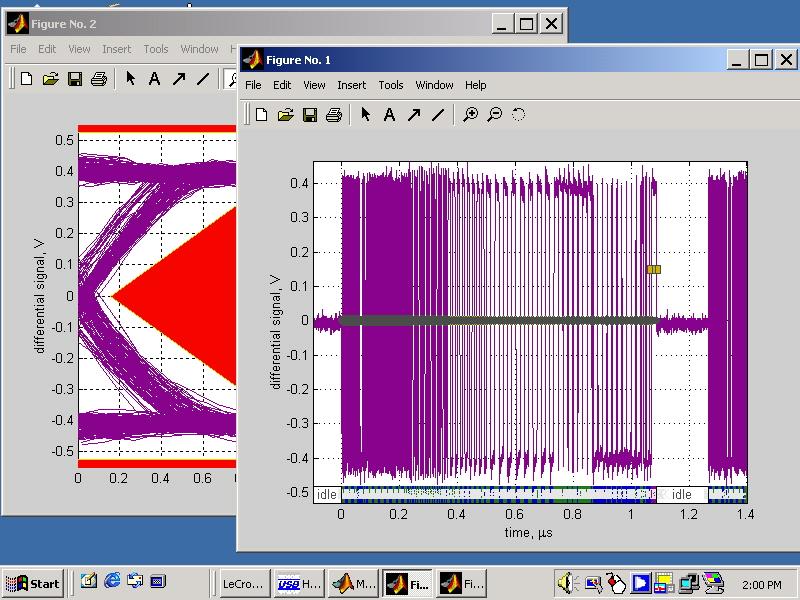
8 Low speed signal quality Full speed signal quality Drop/Droop Interoperability Perform all these tests and record the measurements and summarized Pass/Fail status in Appendix A. 4.4 Host High-speed Signal Quality (EL_2, EL_3, EL_6, EL_7) 1. Select USB2 from the analysis menu of the oscilloscope. In the USB test wizard, select host for the mode and select HS Signal Quality in the Test dialog box. Enter the path and file name for the intermediate result file in the Result File Name dialog box. 2. Attach the 5V power supply to the USB test fixture and verify that the power LED is lit. 3. Verify the green Power LED is lit, and the yellow Test LED is not lit. 4. Connect the host port under test to the A cable on [SQ Host] section of the test fixture. 5. Attach the differential probe to J30 of the test fixture. Ensure the + polarity on the probe lines up with D+ on the fixture. 6. Invoke the High-speed Electrical Test Tool software on the High-speed Electrical Test Bed computer. The main menu appears and shows the USB2.0 host controller. High Speed Electrical Test Tool Main Menu 7. Select host and click the [TEST] button to enter the HS electrical test tool host test menu. 8. Press Next in the USB test wizard menu to start Matlab. If the oscilloscope enters the calibration stat, wait until this finishes and then press next again in the USB test wizard. 9. Select TEST_PACKET from the host Command drop down menu and click [EXECUTE]. This forces the host

![Test packet from host showing cursor placement 12. Enter a descriptive file name in the [Result File Name] dialog box.](/docs-images/74/70235340/images/9-1.jpg "Note that the default directory is D:\Applications\USB2\Results and the file name has the extension *.tsv which is the intermediate result file for the MatLab scripts. The same file name (with a.")
9 under test to continuously transmit test packets. 10. Place the INIT/Test Switch on the fixture in the TEST position. Verify the yellow TEST LED is lit. 11. using the oscilloscope, verify test packets are being transmitted from the port under test. Adjust the cursors so that they are on either side of the test packet on the screen if necessary. Test packet from host showing cursor placement 12. Enter a descriptive file name in the [Result File Name] dialog box. Note that the default directory is D:\Applications\USB2\Results and the file name has the extension *.tsv which is the intermediate result file for the MatLab scripts. The same file name (with a.htm extension) is used for the HTML report file. 13. Press the [Next] key in the LeCroy USB 2.0 test wizard. The MatLab analysis script will be invoked to measure the signal quality. The following two plots will appear on the Windows desktop:
10

11 14. The results displayed are also recorded to an HTML report located in the directory specified in the Data Path control in the test wizard (D:\Applications\USB2\Results by default). Open this file and verify the Signal eye, EOP Width, and Signaling Rate all pass. 15. Note: if there is any irregularities in the captured waveform such as an incorrect EOP width, the Matlab plots shown above will not be displayed and the HML report will not be generated. Check the probe connections to make sure there are no problems. 16. Record the test result in EL_2, EL_3 or EL_4, EL_6 and EL_7. Save all files created during the tests 17. Return the INIT/Test switch of the test fixture back to the Normal position and verify the yellow TEST LED is not lit. 4.5 Host Controller Packet Parameters (EL_21, EL_22, EL_23, EL_25, EL_55) 1. Select Host in the [Mode] control and HS Packet Parameters in the [Test] control of the USB Test Wizard. 2. Connect the Device Signal Quality section of the test fixture [TEST PORT] into B receptacle of a known good high-speed hub. Apply power to the known good hub (referred to as device herein).

12 Note: The use of the Device High-speed Signal Quality test fixture makes it possible to trigger on packets generated by the device because the differential probe is located closer to the device transmitter, hence the device packets are larger in amplitude. 3. Attach the differential probe to J19 on the fixture near the device connector. Ensure + on probe lines up with D+ on fixture. 4. Connect the Device Signal Quality section of the test fixture [INIT PORT] into the host controller port under test. Click [Enumerate Bus] and verify that the device enumerates properly. 5. Press [next] in the USB test wizard to start the test. 6. press enumerate bus in the high speed electrical test tool. If theoscilloscope goes into calibration mode, wait until this finishes and then press [next] in the USB test wizard. 7. In the Host Test menu of the High-speed Electrical Test Tool software, ensure the device is selected (highlighted). Select SINGLE STEP GET DEV DESC from the Downstream Device Control menu and click [EXECUTE] once. 8. The oscilloscope capture should appear as follows. 9. P1 indicates the sync field length in bits which should indicate 31 edges which corresponds to 32 bits. Record the number (P1 + 1) in EL_21.

13 10. Press Next in the test wizard to measure the EOP length (number of bits) of the second packet on the oscilloscope and verify that it is 8 bits per EL_25. This result is shown in P1 and P2. The test passes if either one is 8 bits since the EOP can appear as negative or positive going pulses. Record the result in EL_ Press Next in the test wizard to measure the inter-packet gap between the first two packets shown on the oscilloscope by. The requirement is it must be between 88 bits and 192 bits (EL_23). This result is shown in P1 and P2 for negative and positive going pulses respectively. Record this value in EL_23. The oscilloscope should appear as shown in the following figure. 12. Measure the inter-packet gap between the second and the third packets by pressing the Next button on the test wizard. This value is reported in P1 and P2. The requirement is it must be between 8 bits and 192 bits. (EL_22). Record the computed number of bits in EL_22.
 or positive (P2) must be 40 bits (83.2 ns). Record the result in EL_55. 15. Repeat step 4 through 14 for the remaining ports. 16.")
14 13. On the HS Test Tool, press Step twice and then Enumerate Bus. 14. Press the Next button in the test wizard to measure the SOF EOP width. This value is reported in P1 and P2. The requirement is that either the negative (P1) or positive (P2) must be 40 bits (83.2 ns). Record the result in EL_ Repeat step 4 through 14 for the remaining ports. 16. Remove the Device Signal Quality test fixture and the known good device from the host controller port under test. 4.6 Host Disconnect Detect (EL_36, EL_37) This section uses the Disconnect test fixture to verify the disconnect thresholds of the port under test by simulated disconnect condition. When the TEST switch on the disconnect section of the test fixture is in the Test position, the port under test is subjected to a threshold <525mV. The port should not detect a disconnection. When the TEST switch is in the

15 Normal position, the port under test is subjected to a threshold >625mV. The port should detect a disconnection. 1. Attach the 5V power supply to test fixture (J2). 2. Select Host in the [Mode] control and HS Disconnect in the [Test] control of the USB Test Wizard. 3. Attach the differential probe to J5 of the disconnect section of the fixture. Ensure the + tip on probe lines up with D+ on the fixture. 4. Set the two switches in the disconnect section away from the TEST and LOW positions. This sets the test fixture to emulate a must-not-disconnect threshold. 5. Attach the [INIT] A cable of the disconnect section of the test fixture to the port under test. Start the high speed electrical test tool, select host and then Test. Press [next] in the USB test wizard. 6. In the Host Test menu of the High-speed Electrical Test Tool software select TEST_FORCE_ENABLE from the Port Control window. Enter the port number and click [EXECUTE] once and ensure the operation is successful in the Status Window. Press [Next] in the USB test wizard. 7. Click the Disconnect Notify check box to monitor the disconnect status in the Status Window. 8. Using the oscilloscope, verify the SOF packets are being transmitted from the port under test. The differential amplitude should be less than +/- 525mV (1.05V p-p). Verify that the Status Window does not display Disconnect Event Detected. Record the pass/fail result in EL_ Move the TEST switch of the Disconnect section of the test fixture from its current position and press the

16 Next button on the test wizard. 10. Use the oscilloscope to monitor the differential amplitude of the SOF. It should be greater than +/- 625mV (1.25V p-p). Verify that the Status Window now displays the Disconnect Event Detected. Record the pass/fail result in EL_ Return the TEST switch on the disconnect section of the fixture back to its original position. 12. Repeat step 4 through 9 for all the remaining ports. 13. Remove the Disconnect test fixture from the port under test before proceeding. 4.7 Host CHIRP Timing (EL_33, EL_34, EL_35) 1. Select Host in the [Mode] control and HS Chirp Timing in the [Test] control of the USB Test Wizard. 2. Connect the HS port under test to the [INIT] port of the SQ Device section of the test fixture. Attach a known good device to the Device port of the SQ Device section of the test fixture. Apply power to the known-good device. Make sure the TEST/INIT switch is in the INIT position. 3. Start the HS test tool, select Host Controller/System and push Test. Click [Enumerate Bus].
17 4. Connect the HFP2500 probes from channel 2 to D- of J19 on the test fixture and channel 3 to D+ of J19. Press Next in the test wizard. 5. On the HS test tool, select Enumerate bus and measure the host s Chirp response timing. This is the time between the device s de-assertion of Chirp-K and the start of alternate Chirp-K and Chirp-J sent by the host. The value of P1 indicates the chirp timing. Verify this timing is 100uS. Record the result in EL_ Unplug and re-plug the known-good device from the fixture and press Next in the test wizard. 7. Press Enumerate Bus on the HS test tool and measure the durations of the individual Chirp-K and Chirp-J states. These values are shown in P1 and P2 respectively and should be between 40 and 60 us (EL_31). Record the measurement in EL_34.
18 8. Unplug and re-plug the known good device from the test fixture and press Next in the test wizard. 9. Press Enumerate Bus in the HS test tool. 10. The chirp J/K to SOF time is indicated by P1. This value should be between 100 and 500us. Record this value in EL_35.
19 11. Repeat step 2 through 10 for the remaining down stream facing ports. 4.8 Host Suspend/Resume timing (EL_39, EL_41) 1. Select Host in the Mode control and HS Suspend Resume in the Test control of the USB Test Wizard. 2. Connect the HS port under test to the [INIT] port of the SQ Device section of the test fixture. Attach a known good device to the Device port of the SQ Device section of the test fixture. Apply power to the known-good device. Make sure the TEST/INIT switch is in the INIT position. 3. Start the HS test tool, select Host Controller/System and push Test. Click [Enumerate Bus]. 4. Connect the HFP2500 probes from channel 2 to D- of J19 on the test fixture and channel 3 to D+ of J19. Press Next in the test wizard. 5. On the Host Test menu, select SUSPEND from the Port Control drop down menu and enter the port number. Click [EXECUTE] once to place the port into suspend. The captured suspend transition should appear as in the figure below.

20 6. The parameter P1 shows the time interval from the end of last SOF packet issued by the host to when the device attached its full speed pull-up resistor on D+ (transition to full speed J-state). This time should be between 3.000mS and 3.125ms. Record the Pass/Fail result in EL_ Press Next in the test wizard. 8. On the Host Test menu, select RESUME from the Port Control drop down menu and enter the port number. Click [EXECUTE] once to resume the port. The captured suspend transition should appear as in the figure below.

21 9. The parameter P1 measures the time from the falling edge of D+ to the first SOF issued by the host (EL_41) as shown in the figure above. The value should be less that 3ms. Record the result in EL_41. Note: Repeat the suspend and resume a number of times and verify the time from the falling edge of D+ to the first SOF issued by the host never exceeds 3ms. 10. Repeat step 4 through 9 for all the remaining ports. 11. Unplug the known-good device from the test fixture. Click [Enumerate Bus] once before proceeding. Remove the FET probes from the test fixture.


22 4.9 Host Test J/K, SE0_NAK (EL_8, EL_9) 1. Attach the dongle of the SQ Host section of the test fixture to the port under test. 2. Select TEST_J from the Port Control drop down menu. Enter the port number and click [EXECUTE] once to place the port under test into TEST_J test mode. 3. Using a DVM measure the DC voltage on the D+ line at J30 with respect to ground (the outside pins of J30 are ground pins). Record in section EL_8. 4. Using a DVM measure the DC voltage on the D- line at J7 with respect to ground. Record in section EL_8. 5. On the Host Test menu, select TEST_K from the Port Control drop down menu. Enter the port number and click [EXECUTE] once to place the port under test into TEST_K test mode. 6. Using a DVM measure the DC voltage on the D- line at J30 with respect to ground (the outside pins of J30 are ground pins). Record in section EL_8. 7. Using a DVM measure the DC voltage on the D+ line at J30 with respect to ground. Record in section EL_8. 8. On the Host Test menu, select TEST_SE0_NAK from the Port Control drop down menu. Enter the port number and click [EXECUTE] once to place the port under test into TEST_SE0_NAK test mode.
. Record in section EL_9. 11.")
23 9. Using a DVM measure the DC voltage on the D+ line at J30 with respect to ground (the outside pins of J30 are ground pins). Record in section EL_ Using a DVM measure the DC voltage on the D- line at J30 with respect to ground (the outside pins of J30 are ground pins). Record in section EL_ Repeat step 1 through 10 for the remaining ports.
24 Appendix A A.4 Host High-speed Electrical Test Data This section is for recording the actual test result. Please use a copy for each device to be tested. A.4.2 Vendor and Product Information Test Date Vendor Name Vendor Complete Address Vendor Phone Number Vendor Contact, Title Test ID Number Product Name Product Model and Revision USB Silicon Vendor Name USB Silicon Model USB Silicon Part Marking USB Silicon Stepping Tested By Please fill in all fields. Please contact your silicon supplier if you are unsure of the silicon information. A.4.3 Legacy USB Compliance Tests Legacy USB Compliance Checklist Legacy Test Downstream Ports P1 P2 P3 P4 P5 Comments
25 LS SQ FS SQ Drop/ Droop Interop P = PASS F = FAIL N/A = Not applicable A.4.4 Host High-speed Signal Quality (EL_2, EL_3, EL_6, EL_7) EL_2 A USB 2.0 high-speed transmitter data rate must be 480 Mb/s ±0.05%. Reference documents: USB 2.0 Specification, Section Port P1 P2 P3 P4 P5 PASS FAIL NA Overall Result: Comments: EL_3 A USB 2.0 downstream facing port must meet Template 1 transform waveform requirements measured at TP2 (each host downstream port). Reference documents: USB 2.0 Specification, Section Port P1 P2 P3 P4 P5 PASS FAIL NA Overall Result: Pass Comments: EL_6 A USB 2.0 HS driver must have 10% to 90% differential rise and fall times of greater than 500 ps.
26 Reference documents: USB 2.0 Specification, Section Port P1 P2 P3 P4 P5 PASS FAIL NA Pass Comments: EL_7 A USB 2.0 HS driver must have monotonic data transitions over the vertical openings specified in the appropriate eye pattern template. Reference documents: USB 2.0 Specification, Section Port P1 P2 P3 P4 P5 PASS FAIL NA Comments: A.4.5 Host Controller Packet Parameters (EL_21, EL_22, EL_23, EL_25, EL_55) EL_21 The SYNC field for all transmitted packets (not repeated packets) must begin with a 32-bit SYNC field. Reference documents: USB 2.0 Specification, Section 8.2. SOF SYNC field Comment: Data Packet SYNC field Comment:
27 EL_25 The EOP for all transmitted packets (except SOFs) must be an 8-bit NRZ byte of without bit stuffing. (Note, that a longer EOP is waiverable) Reference documents: USB 2.0 Specification, Section Comment: EL_23 Hosts transmitting two packets in a row must have an inter-packet gap of at least 88 bit times and not more than 192 bit times. Reference documents: USB 2.0 Specification, Section Comment: EL_22 When transmitting after receiving a packet, hosts and devices must provide an inter-packet gap of at least 8 bit times and not more than 192 bit times. Reference documents: USB 2.0 Specification, Section Comment: EL_55 Hosts transmitting SOF packets must provide a 40-bit EOP without bit stuffing where the first symbol of the EOP is a transition from the last data symbol. Reference documents: USB 2.0 Specification, Section Comment: A.4.6 Host Disconnect Detect (EL_36, EL_37) EL_37 A USB 2.0 downstream facing port must not detect the high-speed disconnect state when the amplitude of the differential signal at the downstream facing driver s connector is < =525 mv. Reference documents: USB 2.0 Specification, Section Port P1 P2 P3 P4 P5
28 PASS FAIL NA Overall: Comment: EL_36 A USB 2.0 downstream facing port must detect the high-speed disconnect state when the amplitude of the differential signal at the downstream facing driver s connector is 625 mv. Reference documents: USB 2.0 Specification, Section Port P1 P2 P3 P4 P5 PASS FAIL NA Overall: Comment: A.4.7 Host CHIRP Timing (EL_33, EL_34, EL_35) EL_33 Downstream ports start sending and alternating sequence of Chirp K s and Chirp J s within 100us after the device Chirp K stops. Reference documents: USB 2.0 Specification, Section Comment: EL_34 Downstream port Chirp K and Chirp J durations must be between 40us and 60us duration. Reference documents: USB 2.0 Specification, Section
29 Comment: EL_35 Downstream ports begin sending SOFs within 500us and not sooner than l00us from transmission of the last Chirp (J or K). Reference documents: USB 2.0 Specification, Section Comment: A.4.8 Host Suspend/Resume timing (EL_39, EL_41) EL_39 A device must support the Suspend state. Reference documents: USB 2.0 Specification, Section Comment: EL_41 After resuming a port, the host must begin sending SOFs within 3ms of the start of the idle state. Reference documents: USB 2.0 Specification, Section Comment: A.4.9 Host Test J/K, SE0_NAK (EL_8, EL_9) EL_8 When either D+ or D- are driven high, the output voltage must be 400 mv ±10% when terminated with precision 45 Ω resistors to ground. Reference documents: USB 2.0 Specification, Section
30 Port Test D+ D- D+ D- D+ D- D+ D- D+ D- TEST_J TEST_K Comment: EL_9 When either D+ and D- are not being driven, the output voltage must be OV ±10 mv when terminated with precision 45 Ω resistors to ground. Reference documents: USB 2.0 Specification, Section Port Signal D+ D- D+ D- D+ D- D+ D- D+ D- Measure WRT Ground (mv) Comment:
Universal Serial Bus Implementers Forum Host High-speed Electrical Test Procedure
 Universal Serial Bus Implementers Forum Host High-speed Electrical Test Procedure Revision 1.0 Dec 23, 2001 1 Revision History Rev Date Filename Comments 0.8 26-Jun-2001 Host HS Test.DOC Initial draft
Universal Serial Bus Implementers Forum Host Hi-Speed Electrical Test Procedure For Agilent Infiniium
 Universal Serial Bus Implementers Forum Host Hi-Speed Electrical Test Procedure For Agilent Infiniium Revision 1.3 May 24, 2004 1 Host Hi-Speed Electrical Test Procedure for Agilent Infiniium Revision
Universal Serial Bus 2.0 Host Compliance Test Procedure
 Universal Serial Bus 2.0 Host Compliance Test Procedure 2nd Edition Introduction Purpose Trademarks Revisions The USB-IF Hi-Speed Electrical Test Procedures are developed by the USB 2.0 Compliance Committee
Universal Serial Bus Implementers Forum Device High-speed Electrical Test Procedure For Agilent Infiniium 54846
 Universal Serial Bus Implementers Forum Device High-speed Electrical Test Procedure For Agilent Infiniium 54846 Revision 1.1 August 23, 2003 1 Revision History Rev Date Filename Comments 0.9 (Beta) Nov-23-2001
Universal Serial Bus Implementers Forum Hub Hi-Speed Electrical Test Procedure For Yokogawa DL9240/DL9240L/DL6154
 Universal Serial Bus Implementers Forum Hub Hi-Speed Electrical Test Procedure For Yokogawa DL9240/DL9240L/DL6154 Revision 2.0 November 29, 2010 Revision History Rev Date Filename Comments 1.0 July-27-2006
USB2.0 - Device. Universal Serial Bus Measurement
 USB2.0 - Device Universal Serial Bus Measurement www.tektronix.com 2015-05-05 REVISION RECORD SHEET Version Completion Initiator Page Date s 0.8 7-7-2014 S. Harrison 56 First Draft Nature of Change i ii
USB 2.0 High-Speed Peripheral Compliance Test Report
 USB 2.0 High-Speed Peripheral Compliance Test Report Company Name Suprema Inc. Model Name RealScan-G10 Model Number RS-G10 Product Revision V01A Test Date 9.16.2011 Test Result PASS 267-2, Seohyeon-dong,
USB 2.0 Hi-speed Peripheral Compliance Test Report
 USB 2.0 Hi-speed Peripheral Compliance Test Report USB-IF Compliance Program Company Name SUPREMA INC. Model Name BioMini Plus (SFR500) Model Number SFR500 Product Revision V02A Test Date March 6, 2012
USB2.0 Type-C & Regular USB Device Electrical Compliance test procedure
 P a g e 1 USB2.0 Type-C & Regular USB Device Electrical Compliance test procedure Version 0.85-27 July 2017 P a g e 2 Contents 1. Reference... 3 2. Background... 3 3. Required equipment and software...
Embedded Host High Speed Electrical Test Procedure
 Embedded Host High Speed Electrical Test Procedure Revision 1.01 December 2018 1 P a g e Table of content 1. Reference... 3 2. Background... 3 3. Test Mode Support... 4 3.1 Setup... 4 3.2 USB High Speed
Today s Schedule. USB 2.0 Overview. USB 2.0 Compliance Testing. Demo of the Agilent Solution Q&A
 N5416A Automated USB 2.0 Pre-Compliance Test Solutions Today s Schedule USB 2.0 Overview USB 2.0 Compliance Testing Examples of Compliance Tests Demo of the Agilent Solution Q&A USB 2.0 Overview USB Integrators
Compliance test method and detailed spec for - USB2.0. Tektronix Korea YJ.PARK
 Compliance test method and detailed spec for - USB2.0 Tektronix Korea YJ.PARK 1 Agenda Introduction to USB2.0 Architecture Overview Frame Work and Data Transfer USB2.0 Spec. and Compliance testing Tektronix
PCI Express Signal Quality Test Methodology
 PCI Express Signal Quality Test Methodology Users Guide LeCroy SDA 6000 October 2003 Revision 0.7 Document Number: XXXX DISCLAIMER OF WARRANTIES THIS SPECIFICATION IS PROVIDED AS IS AND WITH NO WARRANTIES
USB 2.0 Test Report For Peripheral
 2.0 Test Report For Peripheral Company Name: Holtek Semiconductor Inc. VID (Dec or Hex): 0x04D9 The VID for the company who apply the USB-IF logo. Model Name: HT66FB582 Product Type: Keyboard Report Date:
Embedded High-speed Host Electrical Test Procedure. Revision 1.01 May 5, 2006
 Embedded High-speed Host Electrical Test Procedure Revision 1.01 May 5, 2006 Table of Contents 1. Preamble... 3 1.1 Revision History... 3 1.2 Reference Documents... 3 1.3 Acronyms... 3 2. Background...
USB Compliance Test Software for Infiniium Oscilloscopes
 DATA SHEET USB Compliance Test Software for Infiniium Oscilloscopes N5416A and N5417A Easily Verify USB Electrical Parameters The N5416A USB compliance test software for Infiniium oscilloscopes gives you
Application Report. 1 Introduction. Device Applications...
 Application Report SPRAAT4 February 2008 TMS320DM6467 Electrical Compliance to the USB 2.0 Specification Device Applications... ABSTRACT This application report describes the TMS320DM6467 electrical compliance
USB 2.0 Test Report for High Speed Device
 USB 2.0 Test Report for High Speed Device Company Name: Silicon Motion, Inc. Model Name: SM324 Product Type: Mass Storage Product Receive Date: Test Start Date: 02/06/2007 Report Date: 02/08/2007 Test
Allion HSEHET User Manual
 Allion HSEHET User Manual High Speed Embedded Host Electrical Test Board Basic Function: Part No. Function SW Reset USB connection and force Host Under Test to detect HSEHET again Switch to change the
USB 2.0 Test Report For Full Speed Device
 USB 2.0 Test Report For Full Speed Device Company Name: Holtek VID (Dec or Hex): 1241 The VID for the company who applies the USB-IF logo. Model Name: HT68FB540 Product Type: HID Report Date: 2013/02/01
USB 2.0 Test Report For Full Speed Device
 USB 2.0 Test Report For Full Speed Device Company Name: Holtek Semiconductor VID (Dec or Hex): 1241 The VID for the company who applies the USB-IF logo. Model Name: HT82A824R Product Type: Audio Class
Signals and Encoding
 Signals and Encoding 18 Signals and Encoding You can design and program a USB peripheral without knowing all of the details about how the data is encoded on the bus. But understanding something about these
Q2 QMS/QFS 16mm Stack Height Final Inch Designs In PCI Express Applications Generation Gbps. Revision Date: February 13, 2009
 Q2 QMS/QFS 16mm Stack Height Final Inch Designs In PCI Express Applications Generation 2 5.0 Gbps Revision Date: February 13, 2009 Copyrights and Trademarks Copyright 2009 Samtec, Inc. Developed in conjunction
USB Compliance Checklist
 USB Compliance Checklist Peripheral Silicon (excluding hubs) July 19, 1999 USB Device Product Information Date July 19, 1999 Vendor Name Motorola Vendor Street Address Vendor City, State, Zip Vendor Phone
RiseUp RU8-DP-DV Series 19mm Stack Height Final Inch Designs in PCI Express Applications. Revision Date: March 18, 2005
 RiseUp RU8-DP-DV Series 19mm Stack Height Final Inch Designs in PCI Express Applications Revision Date: March 18, 2005 Copyrights and Trademarks Copyright 2005 Samtec, Inc. Developed in conjunction with
USB 2.0 Full Speed Certification Report
 Page: 1 13 SUBJECT: LUMIO Crystal Touch DATE: 14 December 2010 USB 2.0 Full Speed Certification Report Customer: LUMIO Ligad 2 Building 4 Mayan Street 71700 Modi in Industrial Park ISRAEL Device: LUMIO
Universal Serial Bus Implementers Forum Full and Low Speed Electrical and Interoperability Compliance Test Procedure
 Universal Serial Bus Implementers Forum Full and Low Speed Electrical and Interoperability Compliance Test Procedure *High Speed Electrical Test Procedures Are Documented Separately Revision 1.3 RC1 January
Agilent N5394A DVI Electrical Performance Validation and Compliance Software
 Agilent N5394A DVI Electrical Performance Validation and Compliance Software Compliance Testing Methods of Implementation Agilent Technologies Notices Agilent Technologies, Inc. 2004-2008 No part of this
Q Pairs QTE/QSE-DP Final Inch Designs In PCI Express Applications 16 mm Stack Height
 Application Note Q Pairs QTE/QSE-DP Final Inch Designs In PCI Express Applications 16 mm Stack Height Copyrights and Trademarks Copyright 2004 Samtec, Inc. Developed in conjunction with Teraspeed Consulting
USB 2.0 Test Report for Full Speed Device
 USB 2.0 Test Report for Full Speed Device Company Name: Holtek Semiconductor Inc. Model Name: HT82A6208 Product Type: HID device Product Receive Date: 2009/08/26 Test Start Date: 2009/08/27 Report Date:
Understanding and Performing USB 2.0 Electrical Testing and Debugging APPLICATION NOTE
 Understanding and Performing USB 2.0 Electrical Testing and Debugging Introduction Engineers involved in the design, characterization and validation of Universal Serial Bus Revision 2.0 (USB 2.0) devices
USB 2.0 Compliance Testing with Agilent Infiniium Oscilloscopes
 USB 2.0 Compliance Testing with Agilent Infiniium Oscilloscopes Application Note 1400 Table of Contents Introduction......................1 Basic Specifications............... 2 Full/Low-Speed Test Suite..........
QPairs QTE/QSE-DP Multi-connector Stack Designs In PCI Express Applications 16 mm Connector Stack Height REVISION DATE: OCTOBER 13, 2004
 Application Note QPairs QTE/QSE-DP Multi-connector Stack Designs In PCI Express Applications 16 mm Connector Stack Height REVISION DATE: OCTOBER 13, 2004 Copyrights and Trademarks Copyright 2004 Samtec,
USB2.0/3.2/BC1.2 Drop Droop Test for non-usb Type-C Products
 P a g e 1 USB2.0/3.2/BC1.2 Drop Droop Test for non-usb Type-C Products Version 1.4 30 April 2018 P a g e 2 Contents Contents... 2 1. Equipment... 3 2. Test hardware... 4 3. Vbus drop droop requirements...
PCI Express Link/Transaction Test Methodology
 PCI Express Link/Transaction Test Methodology September 29, 2006 Revision 1.1 This page is intentionally left blank. 2 PCI Express Link/Transaction Test Methodology, Rev 1.1 Revision History Document
Keysight N5416A and N5417A USB Compliance Test Software for Infiniium Oscilloscopes. Data Sheet
 Keysight N5416A and N5417A USB Compliance Test Software for Infiniium Oscilloscopes Data Sheet 02 Keysight N5416A and N5417A USB Compliance Test Software for Infiniium Oscilloscopes - Data Sheet Easily
USB Compliance Checklist Hubs (Excluding Root Hubs) USB Device Product Information
 USB Device Product Information") USB Compliance Checklist For the 2.0 USB Specification Checklist Version 1.07 USB Device Product Information field Date Vendor Name Vendor Street Address Vendor City, State, Postal Code Vendor Country
USB Compliance Checklist For the 2.0 USB Specification Checklist Version 1.07 USB Device Product Information field Date Vendor Name Vendor Street Address Vendor City, State, Postal Code Vendor Country
Keysight DSOX4USBSQ and DSOX6USBSQ USB 2.0 Signal Quality Test Option for 4000 and 6000 X-Series. Data Sheet
 Keysight DSOX4USBSQ and DSOX6USBSQ USB 2.0 Signal Quality Test Option for 4000 and 6000 X-Series Data Sheet Introduction The low-speed, full-speed, and hi-speed USB 2.0 serial bus is used today for not
5 Performance Verification
 5 Performance Verification Performance Verification TEST EQUIPMENT REQUIRED This procedure can be used to verify the warranted characteristics of the CP015 Current Probe. The recommended calibration interval
PCI Express (Rev1.1) Test Methodologies Data Signal Quality; Reference Clock Jitter
 Test Methodologies Data Signal Quality; Reference Clock Jitter") PCI Express (Rev1.1) Test Methodologies Data Signal Quality; Reference Clock Jitter Users Guide for: Tektronix Real Time Oscilloscopes (DSA/DPO70000 Series, TDS6000B/C Series, or TDS7704B) September 2006
PCI Express (Rev1.1) Test Methodologies Data Signal Quality; Reference Clock Jitter Users Guide for: Tektronix Real Time Oscilloscopes (DSA/DPO70000 Series, TDS6000B/C Series, or TDS7704B) September 2006
Technical Guide. USB 3.1 xhci-based Certification Platform. USB-IF USB 3.1 Peripheral Development Kit: USB3.1 certification Platform.
 Technical Guide USB-IF USB 3.1 Peripheral Development Kit: USB3.1 certification Platform USB 3.1 xhci-based Certification Platform January 26, 2018 Revision 2.0 About this Document Content Owner Author
AN10035_1 Comparing energy efficiency of USB at full-speed and high-speed rates
 Comparing energy efficiency of USB at full-speed and high-speed rates October 2003 White Paper Rev. 1.0 Revision History: Version Date Description Author 1.0 October 2003 First version. CHEN Chee Kiong,
Technical Guide. USB 3.1 xhci-based Certification Platform. USB-IF USB 3.1 Peripheral Development Kit: USB3.1 certification Platform.
 Technical Guide USB-IF USB 3.1 Peripheral Development Kit: USB3.1 certification Platform USB 3.1 xhci-based Certification Platform March 13, 2018 Revision 2.1 About this Document Content Owner Author Approval
TDSUSB2 Universal Serial Bus Measurement Package
 TDSUSB2 Universal Serial Bus Measurement Package 077-0015-03 This document supports software version 3.0.3 and above. www.tektronix.com Copyright Tektronix. All rights reserved. Licensed software products
Teledyne LeCroy. Teledyne LeCroy MOI for DisplayPort PHY CTS 1.2b Source Testing
 Teledyne LeCroy DisplayPort Standard April, 2016 Teledyne LeCroy MOI for DisplayPort PHY CTS 1.2b Source Testing This document is provided "AS IS" and without any warranty of any kind, including, without
PCI Express TM Architecture. PHY Electrical Test Considerations Revision 1.1
 PCI Express TM Architecture PHY Electrical Test Considerations Revision 1.1 February 2007 i PHY ELECTRICAL TEST CONSIDERATIONS, REVISION 1.1 REVISION REVISION HISTORY DATE 1.0 Initial Release. 4/26/2004
DisplayPort * Interposer Test Fixture
 DisplayPort * Interposer Test Fixture DPI-P2RP / Plug to Receptacle Fixture: Features: The Interposer allows connection of test equipment to the DisplayPort interface signals. The fixture has been designed
Agilent N5410A Fibre Channel Automated Test Application
 Agilent N5410A Fibre Channel Automated Test Application Compliance Testing Methods of Implementation Agilent Technologies Notices Agilent Technologies, Inc. 2005 No part of this manual may be reproduced
HDMI Electrical, Protocol Audio Video ( PAV ) and Content Protection, HDCP
 and Content Protection, HDCP") HDMI Electrical, Protocol Audio Video ( PAV ) and Content Protection, HDCP Application of ZX200 ZX201 ZX201L HDMI electrical testing Zebax offers high quality HDMI breakout adapters ( aka test boards )
HDMI Electrical, Protocol Audio Video ( PAV ) and Content Protection, HDCP Application of ZX200 ZX201 ZX201L HDMI electrical testing Zebax offers high quality HDMI breakout adapters ( aka test boards )
S2R72A11 Application Note
 S2R72A11 Application Note Rev.1.00 NOTICE No part of this material may be reproduced or duplicated in any form or by any means without the written permission of Seiko Epson. Seiko Epson reserves the right
Agilent Technologies N5393A PCI Express Electrical Performance Validation and Compliance Software for Infiniium 54855A or Series Oscilloscopes
 Agilent Technologies N5393A PCI Express Electrical Performance Validation and Compliance Software for Infiniium 54855A or 80000 Series Oscilloscopes Data Sheet Verify and debug your PCI Express designs
X-Stream Oscilloscope Version Release Notes
 X-Stream Oscilloscope Version 4.3.1 Release Notes Product All X-Stream Scopes support for IE5 support for D500PT probe overlain parameter measurement results Pattern selection for qualified triggers clearing
EVB-USB2514Q48 48-Pin QFN Evaluation Board Revision A1
 EVB-USB2514Q48 48-Pin QFN Evaluation Board Revision A1 Copyright 2007 SMSC or its subsidiaries. All rights reserved. The information contained herein is proprietary to SMSC and shall be used solely in
USER GUIDE. Atmel OLED1 Xplained Pro. Preface
 USER GUIDE Atmel OLED1 Xplained Pro Preface Atmel OLED1 Xplained Pro is an extension board to the Atmel Xplained Pro evaluation platform. The board enables the user to experiment with user interface applications
Keysight Technologies N6468A SFP+ Electrical Performance Validation and Conformance Software
 Keysight Technologies N6468A SFP+ Electrical Performance Validation and Conformance Software For Infiniium Oscilloscopes Data Sheet 02 Keysight N6468A SFP+ Electrical Performance Validation and Conformance
USB 2.0 Application Software
 USB 2.0 Application Software USB, SR-USB, and DPO4USB Data Sheet Applications Low-speed USB 2.0 Full-speed USB 2.0 High-speed USB 2.0 Features & Benefits USB USB 2.0 Compliance Testing Automated Compliance
Enhanced Serial Peripheral Interface (espi) ECN
 ECN") Enhanced Serial Peripheral Interface (espi) ECN Engineering Change Notice TITLE Clarify OOB packet payload DATE 10 January 2014 AFFECTED DOCUMENT espi Base Specification Rev 0.75 DISCLOSURE RESTRICTIONS
Enhanced Serial Peripheral Interface (espi) ECN Engineering Change Notice TITLE Clarify OOB packet payload DATE 10 January 2014 AFFECTED DOCUMENT espi Base Specification Rev 0.75 DISCLOSURE RESTRICTIONS
USB Implementers Forum Compliance Document USB 2.0 Interoperability and EHCI Test Procedures
 USB Implementers Forum Compliance Document USB 2.0 and EHCI Test Procedures Revision 1.2 January 2017 Table of Figures: Figure 1: USB 2.0 EHCI Configuration When Product Under Test is a Peripheral Figure
Agilent N5393B PCI Express Automated Test Application
 Agilent N5393B PCI Express Automated Test Application Compliance Testing Methods of Implementation Agilent Technologies Notices Agilent Technologies, Inc. 2004-2009 No part of this manual may be reproduced
N5416A USB Demo Guide
 Demo Guide This N5416A Demo Guide consists of : A single slide demo description followed by : Step 1 - instructions on how to connect all the equipment Step 2 - instructions on the configuration of the
USB 2.0 Application Software
 USB 2.0 Application Software TDSUSB2, SR-USB, and DPO4USB Data Sheet Applications Low-speed USB 2.0 Full-speed USB 2.0 High-speed USB 2.0 Features & Benefits TDSUSB2 USB 2.0 Compliance Testing Automated
SEAM-RA/SEAF-RA Series Final Inch Designs in PCI Express Applications Generation GT/s
 SEAM-RA/SEAF-RA Series Final Inch Designs in PCI Express Applications Generation 3-8.0 GT/s Copyrights and Trademarks Copyright 2011 Samtec, Inc. Developed in conjunction with Teraspeed Consulting Group
Revision: 0.30 June Intel Server Board S1200RP UEFI Development Kit Firmware Installation Guide
 Revision: 0.30 June 2016 Intel Server Board S1200RP UEFI Development Kit Firmware Installation Guide Intel Server Board S1200RP UEFI Development Kit Firmware Installation Guide INFORMATION IN THIS DOCUMENT
LAN9513/LAN9513i. USB 2.0 Hub and 10/100 Ethernet Controller PRODUCT FEATURES PRODUCT PREVIEW. Highlights. Target Applications.
 LAN9513/LAN9513i 2.0 Hub and 10/100 Ethernet Controller PRODUCT FEATURES Data Brief Highlights Three downstream ports, one upstream port Three integrated downstream 2.0 PHYs One integrated upstream 2.0
QT3 Xplained Pro. Preface. Atmel QTouch USER GUIDE
 Atmel QTouch QT3 Xplained Pro USER GUIDE Preface The Atmel QT3 Xplained Pro is an extension board, which enables the evaluation of a capacitive touch 12 key numpad in mutual capacitance configuration.
DataPort 250 USB 2.0 Enclosure User s Guide (800)
") DataPort 250 USB 2.0 Enclosure User s Guide WWW.CRU-DATAPORT.COM (800) 260-9800 TABLE OF CONTENTS PAGE Package Contents 1 Features and Requirements 2 Installation 4 Trouble Shooting 13 Technical Support
DataPort 250 USB 2.0 Enclosure User s Guide WWW.CRU-DATAPORT.COM (800) 260-9800 TABLE OF CONTENTS PAGE Package Contents 1 Features and Requirements 2 Installation 4 Trouble Shooting 13 Technical Support
Technical Committee. Addendum to ATM Physical Medium Dependent Interface Specification for 155 Mb/s Over Twisted Pair Cable (af-phy-0015.
 Technical Committee Addendum to ATM Physical Medium Dependent Interface Specification for 155 Mb/s Over Twisted Pair Cable (af-phy-0015.000) af-phy-0053.000 January 1996 af-phy-053.000 ATM Forum Technical
Simplifying Validation and Debug of USB 3.0 Designs - Tektronix USB Testing Solutions Introduction. name title
 Simplifying Validation and Debug of USB 3.0 Designs - Tektronix USB Testing Solutions Introduction name title Agenda Introduction USB 3.0 SuperSpeed Why USB 3.0? Timeline Cable Transmitter Receiver Protocol
MCCI USB-IF HIGH SPEED DEVICE COMPLIANCE TEST REPORT FOR SAMPLE COMPANY TID#: 1XXXXXX 2/9/2006
 MCCI 3520 Krums Corners Road Ithaca, New York 14850 USA Phone +1-607-277-1029 Fax +1-607-277-6844 www.mcci.com MCCI USB-IF HIGH SPEED DEVICE COMPLIANCE TEST REPORT FOR SAMPLE COMPANY TID#: 1XXXXXX 2/9/2006
Agilent Technologies 1680/90-Series Logic Analyzer. Service Guide. Publication number October 2005
 Service Guide Publication number 01680-97016 October 2005 For Safety information, Warranties, and Regulatory information, see the pages at the end of the book. Copyright Agilent Technologies 2001, 2004-2005
HX2VL Development Kit Guide. Doc. # Rev. *A
 HX2VL Development Kit Guide Doc. # 001-73960 Rev. *A Cypress Semiconductor 198 Champion Court San Jose, CA 95134-1709 Phone (USA): 800.858.1810 Phone (Intnl): 408.943.2600 http://www.cypress.com Copyrights
Optical Evaluation Kit for the ADN2530 Differential VCSEL Driver EVAL-ADN2530
 Optical Evaluation Kit for the ADN2530 Differential VCSEL Driver EVAL-ADN2530 GENERAL DESCRIPTION This data sheet describes the optical evaluation kit for the ADN2530, a 10 Gbps active back-terminated,
A.G.P. Pro Specification
 A.G.P. Pro Specification Revision 1.0 Intel Corporation August 1998 A.G.P. Pro Specification Copyright Intel Corporation 1998 All rights reserved. This specification is provided AS IS with no warranties
Intel Desktop Board DX58SO. MLP Report. Motherboard Logo Program (MLP) 8/10/2009
 8/10/2009") Motherboard Logo Program (MLP) Intel Desktop Board DX58SO MLP Report 8/10/2009 Purpose: This report describes the DX58SO Motherboard Logo Program testing run conducted by Intel Corporation. THIS TEST REPORT
Motherboard Logo Program (MLP) Intel Desktop Board DX58SO MLP Report 8/10/2009 Purpose: This report describes the DX58SO Motherboard Logo Program testing run conducted by Intel Corporation. THIS TEST REPORT
MEC-USB-M002. User s Manual
 MEC-USB-M002 Mini PCI-e 2-port USB 3.0 board User s Manual Third Edition, February 2014 2014 Cervoz Co., Ltd. All rights reserved. Reproduction without permission is prohibited Mini PCI-e USB Card User
HX2VL Development Kit Guide. Doc. # Rev. **
 HX2VL Development Kit Guide Doc. # 001-73960 Rev. ** Cypress Semiconductor 198 Champion Court San Jose, CA 95134-1709 Phone (USA): 800.858.1810 Phone (Intnl): 408.943.2600 http://www.cypress.com Copyrights
PCI-X Protocol Addendum to the PCI Local Bus Specification Revision 2.0a
 PCI-X Protocol Addendum to the PCI Local Bus Specification Revision 2.0a July 22, 2003 REVISION REVISION HISTORY DATE 1.0 Initial release. 9/22/99 1.0a Clarifications and typographical corrections. 7/24/00
Quick Start Guide Agilent Technologies 14565A Device Characterization Software for Windows 98, Windows NT 4.0, Windows 2000 and Windows XP
 Quick Start Guide Agilent Technologies 14565A Device Characterization Software for Windows 98, Windows NT 4.0, Windows 2000 and Windows XP sa Contents Description...3 System Requirements...3 Installing
TCG Storage Work Group. Storage Certification Program. Program Version 1.0 Document Revision 1.22 March 16, Contact: Doug Gemmill, TCG CPM T C G
 TCG Storage Work Group Storage Certification Program Program Version 1.0 Document Revision 1.22 March 16, 2018 Contact: Doug Gemmill, TCG CPM T C G TCG Published Copyright TCG 2018 Copyright 2018 Trusted
Application Note. PCIE-RA Series Final Inch Designs in PCI Express Applications Generation GT/s
 PCIE-RA Series Final Inch Designs in PCI Express Applications Generation 3-8.0 GT/s Copyrights and Trademarks Copyright 2012, Inc. COPYRIGHTS, TRADEMARKS, and PATENTS Final Inch is a trademark of, Inc.
Enhanced Serial Peripheral Interface (espi)
") Enhanced Serial Peripheral Interface (espi) Addendum for Server Platforms December 2013 Revision 0.7 329957 0BIntroduction Intel hereby grants you a fully-paid, non-exclusive, non-transferable, worldwide,
Enhanced Serial Peripheral Interface (espi) Addendum for Server Platforms December 2013 Revision 0.7 329957 0BIntroduction Intel hereby grants you a fully-paid, non-exclusive, non-transferable, worldwide,
Serial ATA International Organization
 SyntheSys Research, Inc. Serial ATA International Organization Version 1.0 June 4, 2009 Serial ATA Interoperability Program Revision 1.4 SyntheSys Research, Inc. MOI for RSG Tests (using BERTScope 7500B
MEC-COM-M114. User s Manual
 MEC-COM-M114 Mini PCI-e 4-port RS-232 serial board with power input User s Manual Third Edition, February 2014 2014 Cervoz Co., Ltd. All rights reserved. Reproduction without permission is prohibited Mini
Agilent N5393C PCI Express Electrical Performance and Compliance Software Release Notes
 Agilent N5393C PCI Express Electrical Performance and Compliance Software Release Notes Agilent N5393C Software Version 03.34 Released Date: 19 May 2014 File Name: SetupInfPCIExpress0334.exe Improved algorithm
Chipset Evaluation and Development Loadboard Version 2
 IA MSC-UGLB2 Chipset Evaluation and Development Loadboard Version 2 User Guide Revision 1.0r IA MSC-UGLB2 rev 1.0r 0907 2007, Silicon Laboratories, Inc. Silicon Labs, Inc. 400 West Cesar Chavez Austin,
PCI-X Addendum to the PCI Compliance Checklist. Revision 1.0a
 PCI-X Addendum to the PCI Compliance Checklist Revision 1.0a August 29, 2000 PCI-X Addendum to the PCI Compliance Checklist REVISION REVISION HISTORY DATE 1.0 Initial Release 3/1/00 1.0a Updates for PCI-X
Application Note. PCIE-EM Series Final Inch Designs in PCI Express Applications Generation GT/s
 PCIE-EM Series Final Inch Designs in PCI Express Applications Generation 3-8.0 GT/s Copyrights and Trademarks Copyright 2015, Inc. COPYRIGHTS, TRADEMARKS, and PATENTS Final Inch is a trademark of, Inc.
AT21CS Series Reset and Discovery. Introduction. Serial EEPROM APPLICATION NOTE
 Serial EEPROM AT21CS Series Reset and Discovery APPLICATION NOTE Introduction This application note discusses the Atmel AT21CS Series Reset function and the AT21CS Series Discovery function. Additionally,
Is Now Part of To learn more about ON Semiconductor, please visit our website at
 Is Now Part of To learn more about ON Semiconductor, please visit our website at www.onsemi.com ON Semiconductor and the ON Semiconductor logo are trademarks of Semiconductor Components Industries, LLC
PCI-X Protocol Addendum to the PCI Local Bus Specification Revision 2.0a
 PCI-X Protocol Addendum to the PCI Local Bus Specification Revision 2.0a July 29, 2002July 22, 2003 REVISION REVISION HISTORY DATE 1.0 Initial release. 9/22/99 1.0a Clarifications and typographical corrections.
EZ-PD Analyzer Utility User Guide
 EZ-PD Analyzer Utility User Guide Doc. No. 002-12896 Rev. ** Cypress Semiconductor 198 Champion Court San Jose, CA 95134-1709 Phone (USA): 800.858.1810 Phone (Intnl): 408.943.2600 www.cypress.com Copyrights
Keysight N5990A DisplayPort Extended Tests Embedded DisplayPort
 Keysight N5990A DisplayPort Extended Tests Embedded DisplayPort Calibration and Test Procedure Descriptions User Guide Notices Keysight Technologies 2018 No part of this manual may be reproduced in any
MEC-SAT-M002. User s Manual
 MEC-SAT-M002 Mini PCI-e 2-port Serial ATA III board User s Manual Third Edition, February 2014 2014 Cervoz Co., Ltd. All rights reserved. Reproduction without permission is prohibited Mini PCI-e SATA Card
USER GUIDE. Atmel QT1 Xplained Pro. Preface
 USER GUIDE Atmel QT1 Xplained Pro Preface Atmel QT1 Xplained Pro kit is an extension board that enables evaluation of self- and mutual capacitance mode using the Peripheral Touch Controller (PTC) module.
QT2 Xplained Pro. Preface. Atmel QTouch USER GUIDE
 Atmel QTouch QT2 Xplained Pro USER GUIDE Preface Atmel QT2 Xplained Pro kit is an extension board that enables the evaluation of a mutual capacitance touch surface using the Peripheral Touch Controller
Ethernet1 Xplained Pro
 Ethernet1 Xplained Pro Part Number: ATETHERNET1-XPRO The Atmel Ethernet1 Xplained Pro is an extension board to the Atmel Xplained Pro evaluation platform. The board enables the user to experiment with
DEMO MANUAL DC1506A LTC4361 Overvoltage/ Overcurrent Protection Controller DESCRIPTION
 DESCRIPTION Demonstration circuit DC1506A features the LTC 4361 an overvoltage/overcurrent protection controller that safeguards 2.5V to 5.5V systems from input supply overvoltage. The LTC4361 is designed
User s Guide. RP7000S Series Single-Ended Active Probe. Nov RIGOL Technologies, Inc.
 User s Guide RP7000S Series Single-Ended Active Probe Nov. 2013 RIGOL Technologies, Inc. Guaranty and Declaration Copyright 2013 RIGOL Technologies, Inc. All Rights Reserved. Trademark Information RIGOL
Agilent N5393C PCI Express Automated Test Application
 Agilent N5393C PCI Express Automated Test Application Compliance Testing Methods of Implementation Agilent Technologies Notices Agilent Technologies, Inc. 2004-2010 No part of this manual may be reproduced
ST19NP18-TPM-I2C Trusted Platform Module (TPM) with I²C Interface Features
 with I²C Interface Features") Trusted Platform Module (TPM) with I²C Interface Data brief Features Single-chip Trusted Platform Module (TPM) Embedded TPM 1.2 firmware I²C communication interface (Slave mode) Architecture based on ST19N
Trusted Platform Module (TPM) with I²C Interface Data brief Features Single-chip Trusted Platform Module (TPM) Embedded TPM 1.2 firmware I²C communication interface (Slave mode) Architecture based on ST19N